

Radio Broadcast - 1924, January - 84 Pages, 8.2 ... - VacuumTubeEra
Radio Broadcast - 1924, January - 84 Pages, 8.2 ... - VacuumTubeEra
Radio Broadcast - 1924, January - 84 Pages, 8.2 ... - VacuumTubeEra

You also want an ePaper? Increase the reach of your titles
YUMPU automatically turns print PDFs into web optimized ePapers that Google loves.
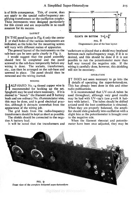
theA Simplified Super-Heterodyne 215is of little consequence. This, of course, doesnot apply to the special radio-frequency amplifyingtransformers or the oscillation coupler.These instruments were designed particularlyfor this circuit and are responsible in no smallmeasure for its success.LAYOUTIN THE panel layout in Fig. 6 onlythe centeror shaft holes of the various instruments areindicated, as the holes for the mounting screwswill vary with different makes of apparatus.The general layout of the instruments on thesub-base can be seen quite clearly in Fig. 7.I would suggest that the panel assemblyshould first be completed and the panelscrewed to the sub-base temporarily before anywiringis done. The sockets, transformers,etc., can then be arranged on the sub-base andscrewed in place. The panel should then beremoved and the wiring started.WIRINGHALF-HARD No. 14 tinned copper wire isrecommended for hooking up the set.Spaghetti may be used where necessary. If it isdesired to "bunch" the filament and B batteryleads and use ordinary No. 1 8 annunciator wire,this may be done, and isgood electrical practice,although it detracts somewhat from theappearance of the wiring job.The grid leads from .radio-frequencytransformers should be kept as short as possible.The shields should be connected to the negativeA battery lead.It will be noted that the transformers andCJ-1


