Spray Height Control System Generic (Fixed Boom) End ... - Norac
Spray Height Control System Generic (Fixed Boom) End ... - Norac
Spray Height Control System Generic (Fixed Boom) End ... - Norac

You also want an ePaper? Increase the reach of your titles
YUMPU automatically turns print PDFs into web optimized ePapers that Google loves.
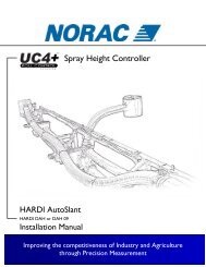
<strong>Spray</strong> <strong>Height</strong> <strong>Control</strong> <strong>System</strong>GN2<strong>Generic</strong>(<strong>Fixed</strong> <strong>Boom</strong>)<strong>End</strong> User Installation Manual
Printed in CanadaCopyright 2010 by NORAC <strong>System</strong>s International Inc.Reorder P/N: UC4+BC+GN2-INSTE Rev B (<strong>Generic</strong> – <strong>Fixed</strong> <strong>Boom</strong>)NOTICE: NORAC <strong>System</strong>s International Inc. reserves the right to improve products and their specifications without notice andwithout the requirement to update products sold previously. Every effort has been made to ensure the accuracy of the informationcontained in this manual. The technical information in this manual was reviewed at the time of approval for publication.
Contents1 Introduction .....................................................................................................12 Parts List ..........................................................................................................23 <strong>Control</strong> Panel Mounting .................................................................................24 Cable Installation ............................................................................................35 Calibration .......................................................................................................46 UC4+ Menu Structure ....................................................................................8
1 IntroductionCongratulations on your purchase of the NORAC UC4+ <strong>Spray</strong> <strong>Height</strong> <strong>Control</strong> <strong>System</strong>. Thissystem is manufactured with top quality components and is engineered using the latesttechnology to provide operating reliability unmatched for years to come.When properly used the system can provide protection from sprayer boom damage, improvesprayer efficiency, and ensure chemicals are applied correctly.Please take the time to read this manual completely before attempting to install the system. Athorough understanding of this manual will ensure that you receive the maximum benefit fromthe system.Your input can help make us better! If you find issues or have suggestions regarding the partslist or the installation procedure, please don’t hesitate to contact us.IMPORTANT:Every effort has been made to ensure the accuracy of the information contacted inthis manual. All parts supplied are selected to specially fit the sprayer to facilitatea complete installation. However, NORAC cannot guarantee all parts fit asintended due to the variations of the sprayer by the manufacturer.Please read this manual in its entirety before attempting installation.1
2 Parts ListItem Part Number Name QuantityC10 44650-35 CABLE POWER GENERIC PULL-TYPE 1C14 44658-28 CABLE INTERFACE UC4 BC C14 POWER PIGTAIL 1E01 4461BC+ UC4 PLUS BOOM CONTROL PANEL 1M01 4476BC+MAN7 OPERATOR MANUAL UC4+ SPRAY HEIGHT CONTROL (FIXED BOOM) 1M03 UC4-BC-GN2-INSTE MANUAL INSTALLATION END-USER GENERIC FIXED BOOM 13 <strong>Control</strong> Panel MountingInstall the UC4+ <strong>Control</strong> Panel (E01) in the cab of the tractor or sprayer with the suppliedmounting bracket. The location must facilitate connecting the power cable (C10) to thebottom of the UC4+ <strong>Control</strong> Panel.Figure 1: UC4+ Panel Mounting2
4 Cable InstallationFigure 2: Cable Routing Overview1. Connect C10 to the UC4+ <strong>Control</strong> Panel in the sprayer cab.2. Route the receptacle end of C10 to the exterior of the cab and connect to C11 at thehitch. Ensure cable is routed in a safe manner to avoid damage.3. Connect cable C14 to an appropriate power supply.3
5 Calibration5.1 Initial Power UpTurn on the power for the UC4+ <strong>Control</strong> Panel using the switch on the side of its chassis.Ensure that the UC4+ display lights up to confirm that the panel has +12 volt power.After a moment the panel will display the Main Run Screen:5.2 ReTuneM 90 MFor optimal performance, the UC4+ <strong>Height</strong> <strong>Control</strong> <strong>System</strong> must be calibrated to the tractorunit powering the sprayer hydraulics. Before you start calibrating the hydraulics ensure youcomplete the following steps:Unfold the sprayer in a location that is relatively level, and where the sensors are over bare soilor gravel. Do not conduct the setup procedure over standing crop, or tall weeds/grass.Ensure the boom roll suspension system is functioning properly and smoothly. Friction onwear surfaces can be relieved using lubricants (grease, etc) or adjustment. Properly tunedsuspension systems will optimize UC4+ performance.For best results, the hydraulic system should be under a normal load and at a normal workingtemperature. Start the solution pump and run the sprayer’s engine at a normal working RPMfor the entire setup. Cycle all boom sections up and down manually for five minutes to warmthe oil. Ensure any hydraulic flow controls are adjusted for normal field operation. Changingthe hydraulic flow controls after or during the system setup will affect the UC4+ performance.To initiate the “ReTune” process, navigate from the Main Run Screen to the “ReTune” menu.Ensure the UC4+ control panel is in manual mode, at the run screen.Toggle "SETUP" until the display shows "Retune?". Toggle "AUTO (YES)" to confirm.The panel will start the “ReTune” process. Follow the on-screen prompts. Additionalinformation concerning the “ReTune” procedure may be found in the UC4+ Operator’sManual.After you have completed the “ReTune”, you will need to manually calibrate the deadzone andgain for the slant valve (Section 5.3).4
5.3 Calibrating the Slant ValveThe roll (slant) valve can only be calibrated manually as described below. When calibrating theroll valve you must first calibrate the deadzone clockwise and counter clockwise settings andthen the gain clockwise and counter clockwise settings.Navigating to the Slant Valve Settings:Ensure the UC4+ control panel is in manual mode, at the run screen.Toggle "SETUP" until the display shows "More?". Toggle "AUTO (YES)" to confirm.Toggle "SETUP" until the display shows "Roll?". Toggle the "AUTO (YES)" switch to confirm.Toggle the "SETUP" switch to access the next menu prompt or toggle "SENSOR DISPLAY" toaccess the previous menu. Choose the dead zone up/down or gain up/down setting (Figure3).Roll OnURoll Channel OnSensorDisplaySetupDZ 20KP 5Roll Channel Dead Zone Clockwise (cw)Roll Channel Gain Clockwise (cw)DZ 20Roll Channel Dead Zone Counter Clockwise (ccw)KP 5Roll Channel Gain Counter Clockwise (ccw)Figure 3: Slant Valve Settings5
Manual Dead Zone Calibration:Follow Section 5.2 Step 1 (level booms, working RPM, etc.) before proceeding.Choose the dead zone up or down setting (Figure 3).Press and hold the "MANUAL" switch.The valve will turn on at the indicated setting for exactly one-second. The screen will show theactual change in height.The change in height reading is live as long as you hold the "MANUAL" switch. Wait until theheight reading has settled to a stable value and record this reading.Average three readings. The acceptable average change in height should be from 20 to 50 mm.If the average is less, increase the DZ setting with the "+/-" switch. If the average is more,decrease the DZ setting with the "+/-" switch.Repeat Steps 3 to 7 until the average falls within 20 to 50 mm.6
Manual Gain Calibration:This test will drive the boom at full speed in the selected direction for one second. Make surethe boom has full range of movement.The purpose of this test is to determine the sprayer boom speeds. It is recommended that youperform each test three times and average your readings. From the speed measurementstaken, use Table 1 to determine the appropriate gain values to use for each function.Follow Section 5.2 Step 1 (level booms, working RPM, etc.) before proceeding.Choose the gain up or down setting (Figure 3).Press and hold the "MANUAL" switch.The valve will turn on at 100 percent speed for exactly one-second, regardless of the value ofthe gain setting. The screen will show the actual change in height.The change in height reading is live as long as you hold the "MANUAL" switch. Wait until theheight reading has settled to a stable value and record this reading. This is your boom speed ininches per second (in/s) or mm per second (mm/s).Repeat Steps 3 to 5 three times, repositioning the boom as necessary. Average your threereadings.Set the gain value using the "+/-" switch using Table 1 below as a guideline.Table 1: Gain SettingsFunction <strong>Boom</strong> Speed (mm/sec) Gain SettingRoll >2200 1Roll 2200 - 1000 1 - 5Roll 1000 - 400 5 - 9Roll 400 - 100 9 - 11Roll
6 UC4+ Menu Structure8
CanadaNORAC <strong>System</strong>s International Inc.Phone: (+1) 306 664 6711Toll Free: 1 800 667 3921Shipping Address:3702 Kinnear PlaceSaskatoon, SKS7P 0A6United StatesNORAC, Inc.Phone: (+1) 952 224 4142Toll Free: 1 866 306 6722Shipping Address:6667 West Old Shakopee Road, Suite 111Bloomington, MN55438EuropeNORAC EuropePhone: (+33) (0)4 26 47 04 42Shipping Address:Rue de l’hermitage01090 GUEREINSFrancewww.norac.ca0