GE Fanuc | GE Series Six 6 | IC600YB921 - GE Fanuc PLC
GE Fanuc | GE Series Six 6 | IC600YB921 - GE Fanuc PLC
GE Fanuc | GE Series Six 6 | IC600YB921 - GE Fanuc PLC

You also want an ePaper? Increase the reach of your titles
YUMPU automatically turns print PDFs into web optimized ePapers that Google loves.
<strong>IC600YB921</strong>New In Stock!<strong>GE</strong> <strong>Fanuc</strong>http://www.pdfsupply.com/automation/ge-fanuc/ge-series-six-6/<strong>IC600YB921</strong>Ge <strong>Series</strong> <strong>Six</strong> 61-919-535-3180In Stock! 5V TTL Output Module with Lights (32 points) IC600YIC600YBwww.pdfsupply.comEmail:sales@pdfsupply.com
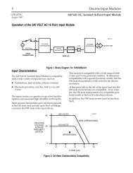
4 High Density TTL<strong>GE</strong>K-84857BInstallationThe High-Density TTL Output module can beinstalled in an I/O rack or in a <strong>Series</strong> <strong>Six</strong> Plus CPUrack. Before installing the module, theDual-In-line-Package (DIP) switches immediatelybehind the card slot on the rack backplane should beset to reserve 32 consecutive bits in the appropriateoutput status table of the CPU. For specific DIPswitch settings, refer to Table 2.The circuit-board jumpers must be set to configure themodule to operate in the desired system configuration.For example: invert or non-invert and disable outputsor hold last state. Refer to Figure 1, User Items.The response to a power-down or <strong>Series</strong> <strong>Six</strong> systemfault is defined by jumper 1 (JPl). Position l-2 (DIS-ABLE OUTPUTS) turns all outputs OFF in suchcases. Position 2-3 (HOLD LAST STATE) wouldmaintain the last commanded state of the outputs untilnew valid data is presented or user power is removed.In either case all outputs are initialized OFF whenuser power is turned on.Jumper 2 (JP2) determines what state commanded bythe CPU is used to tum an output ON. In the Normalmode (non-inverting) the ON state (active low output)results when a logical 1 is in the Output Status Table.Conversely, an OFF state (output high) exists with a 0in the Output Status Table. Just the opposite outputstate versus output status table exists if the module isplaced in the Inverting mode.When using a High-Density Output module to drive aHigh-Density Input module, both modules should beconfigured in the same mode (Inverting orNon-Inverting).Following this procedure ensuresthat the bit values sent from the Output Status Tableto the Input Status Table are not inverted.It is recommended that the extraction/insertion toolfurnished with the CPU be used to remove or installthe circuit boards.With the board in place in the rack,the edge connector on the faceplate should be slippedover the circuit board so that the proper contact ismade. The faceplate can then be secured to the rackusing the thumbscrews at the top and bottom.Refer to Figure 2 for a typical symbolic output circuit.Refer to Figure 3 for typical user connections to thismodule. If active-pullup outputs are desired with thisTTL module, the PUL terminal should be connectedto the positive terminal of the output supply (0 to 15V dc). For open-collector operation, the PUL terminalshould be left open (no connection).
High Density TTL 7<strong>GE</strong>K-84857BTable 3. SpecificationsDimensions:Storage Temperature:Operating Temperature:Humidity:Altitude:Isolation:Power Requirements:User Supplied Power:Output Capabilities:Response Time:Circuit Board: 8.15 x 11.0 (inches) 208 x 280 (mm)Faceplate: 12.46 x 1.175 (inches) 317 x 30 (mm)-20” to60 at the outside of rack.5 to 95% (non-condensing)Up to 10,000 feet above sea level (operating),<strong>Series</strong> <strong>Six</strong> common to user common.2000 V dc for one second (maximum)240 V ac 50/60Hz continuous (maximum).Rate of change (noise immunity) 500 V/microsecond(maximum).Supplied by I/O rack or <strong>Series</strong> 60 rack:+5 V dc, 180 mA maximum or 3 power units.Ref. Chapter 2 section 2, I/O module load, Installationand Maintenance Manual, <strong>GE</strong>K-25361.To user on module logic at terminal 33.Voltage including ripple 5 0.25 V dcCurrent: 550mA (with status indicating LEDs)To user output pull up at terminal 34.Voltage including ripple 0 to 15 V dcEquivalent load resistance = 1.3K number of outputsused.ON state, output lowModule acts as a current sink.25 milliamps per output for TTL compatibility 0.5 V dc.50 milliamps per output point maximum 1.0 V dc.OFF state, output high.Open collector operation if PUL (terminal 34) is leftopen.Sources current as voltage source equal to terminal 34voltage minus 0.6 volts in series with 1.3K resistor.ON to OFF or OFF to ON, 40 microseconds maximum.
High Density TTL<strong>GE</strong>K-84857BNOTEFor previous revisions of 5V TI’LOutput modules (911A and 911B) see <strong>GE</strong>K-83530.Table 4. Ordering InformationModuleCircuit Board andFaceplate Circuit Board Only Faceplate Only5V TTL Output With Status Indicators IC6OOBF921A <strong>IC600YB921</strong>AIC600FP921ACatalog Number Revision SuffixThe equipment iisted above having the catalog numbers shown and the same equipment having a higher alphasuffix is designed for listing by UL for use as auxiliary control devices.The equipment is a direct replacement forequipment having the same catalog number but a lower alpha suffix.Thison the nameplate means the product is listed by Underwriters Laboratories Inc.Standard No.Industrial Control Equipment, subsection Electronic Power Conversion Equipment.)For further information, contact your local <strong>GE</strong> <strong>Fanuc</strong> sales office.<strong>GE</strong> <strong>Fanuc</strong> Automation North America, Inc., Charlottesville, Virginia