Alspa CE80–20 FIP Bus Interface Unit User's Manual
Alspa CE80–20 FIP Bus Interface Unit User's Manual
Alspa CE80–20 FIP Bus Interface Unit User's Manual

Create successful ePaper yourself
Turn your PDF publications into a flip-book with our unique Google optimized e-Paper software.
<strong>Alspa</strong>IC670MDL643New In Stock!Cegelec Alstom <strong>Alspa</strong>http://www.pdfsupply.com/automation/cegelec-alstom-alspa/alspa-ce80-20/<strong>Alspa</strong>IC670MDL643<strong>Alspa</strong> CE80-201-919-535-3180Alstom <strong>Alspa</strong> In Stock! 5/12Vdc Pos./Neg. Logic Input, 16 Point,Grouped IC670M IC670MD IC670MDL Cegelecwww.pdfsupply.comEmail:sales@pdfsupply.com
C E G E L E C<strong>Alspa</strong> <strong>CE80–20</strong><strong>FIP</strong> <strong>Bus</strong> <strong>Interface</strong><strong>Unit</strong> User’s <strong>Manual</strong>ALS 52311 b–enFirst issue: 08–96This edition: 02–98
RevisionsPrefaceReader’scommentsContentsFiguresTablesMeaning of terms that may be used in thisdocument / Notice to readersWARNINGWarning notices are used to emphasize that hazardous voltages, currents,temperatures, or other conditions that could cause personal injury exist ormay be associated with use of a particular equipment.In situations where inattention could cause either personal injury ordamage to equipment, a Warning notice is used.Warning notices are used to emphasize that hazardous voltages, currents,temperatures, or other conditions that could cause personal injury exist ormay be associated with use of a particular equipment.In situations where inattention could cause either personal injury ordamage to equipment, a Warning notice is used.CautionCaution notices are used where there is a risk of damage to equipment forexample.NoteNotes merely call attention to information that is especially significant tounderstanding and operating the equipment.This document is based on information available at the time of its publication. While efforts have been made to be accurate, the informationcontained herein does not purport to cover all details or variations in hardware or software, nor to provide for every possible contingency inconnection with installation, operation, or maintenance. Features may be described herein which are not present in all systems. Cegelec assumesno obligation of notice to holders of this document with respect to changes subsequently made.Cegelec makes no representation or warranty, expressed, implied, or statutory with respect to, and assumes no responsibility for the accuracy,completeness, sufficiency, or usefulness of the information contained herein. Cegelec gives no warranties of merchantability or fitness forpurpose shall apply.In this publication, no mention is made of rights with respect to trademarks or tradenames that may attach to certain words or signs. The absenceof such mention, however, in no way implies there is no protection.Partial reproduction of this document is authorized, but limited to internal use, for information only and for no commercial purpose.However, such authorization is granted only on the express condition that any partial copy of the document bears a mention of its property,including the copyright statement.All rights reserved© Copyright 1997, Cegelec, Levallois–Perret (France)Page 2<strong>Alspa</strong> <strong>CE80–20</strong> <strong>FIP</strong> <strong>Bus</strong> <strong>Interface</strong> <strong>Unit</strong> User’s <strong>Manual</strong>ALS 52311 b–en
RevisionsIndex letter Date Nature of revisionb 02–98 Availability of V2 of <strong>FIP</strong> BIU (changes to functional specifications,operation and I/O modules available).ALS 52311 b–en <strong>Alspa</strong> <strong>CE80–20</strong> <strong>FIP</strong> <strong>Bus</strong> <strong>Interface</strong> <strong>Unit</strong> User’s <strong>Manual</strong>Page 3
RevisionsPage 4<strong>Alspa</strong> <strong>CE80–20</strong> <strong>FIP</strong> <strong>Bus</strong> <strong>Interface</strong> <strong>Unit</strong> User’s <strong>Manual</strong>ALS 52311 b–en
Preface1. CONTENT OF THIS MANUALThis manual describes the <strong>Alspa</strong> <strong>CE80–20</strong> <strong>FIP</strong> <strong>Bus</strong> <strong>Interface</strong> <strong>Unit</strong>. It explains operation of the <strong>Bus</strong> <strong>Interface</strong> <strong>Unit</strong>as a <strong>FIP</strong> bus device (CE670FBI001/FBI002).Chapter 1. Introduction: Chapter 1 introduces <strong>Alspa</strong> <strong>CE80–20</strong> systems, the <strong>FIP</strong> <strong>Bus</strong> <strong>Interface</strong> <strong>Unit</strong>, the <strong>Bus</strong><strong>Interface</strong> <strong>Unit</strong> Power Supply, and the <strong>Bus</strong> <strong>Interface</strong> <strong>Unit</strong> Terminal Block, and lists their specifications.Chapter 2. Installation: Chapter 2 describes <strong>Bus</strong> <strong>Interface</strong> <strong>Unit</strong> installation and gives system installationguidelines.Chapter 3. Operation: Chapter 3 explains how a <strong>Bus</strong> <strong>Interface</strong> <strong>Unit</strong> interacts with the modules in its station, howit stores data, and how it exchanges data with a PLC or other type of system host.Chapter 4. Hand-held Programmer Functions: Chapter 4 explains how to use a Hand-held Programmer witha <strong>FIP</strong> <strong>Bus</strong> <strong>Interface</strong> <strong>Unit</strong>.2. RELATED PUBLICATIONSFor more information, refer to these publications:ALS 52308 <strong>Alspa</strong> <strong>CE80–20</strong> I/O Modules User’s <strong>Manual</strong>. This book describes <strong>Alspa</strong> <strong>CE80–20</strong> I/O Modules andI/O Terminal Blocks and explains how to install them.ALS 52310 <strong>FIP</strong> <strong>Bus</strong> Controller (FBC) for <strong>Alspa</strong> C80–75 PLC User’s <strong>Manual</strong>. Reference manual for the <strong>Bus</strong>Controller, which interfaces a <strong>FIP</strong> bus to an <strong>Alspa</strong> C80–75 PLC. This book describes the installation and operationof the <strong>Bus</strong> Controller. It also contains the programming information needed to interface <strong>FIP</strong> devices to an <strong>Alspa</strong>C80–75 PLC.ALS 52311 b–en <strong>Alspa</strong> <strong>CE80–20</strong> <strong>FIP</strong> <strong>Bus</strong> <strong>Interface</strong> <strong>Unit</strong> User’s <strong>Manual</strong>Page 5
Preface3. MANUAL NUMBERSIn some cases, <strong>Alspa</strong> 8000 manuals may be issued with numbers that differ from the one given under ”RelatedPublications” in the Preface of other manuals, or in Important Product Information or data sheets.The contents are similar.The table below shows the correspondence between ”ALS” and equivalent numbers for the manuals concerned:ALS NumberALS 52113ALS 52302ALS 52303ALS 52404ALS 52405ALS 52503Other NumberGFK–0600GEK–90486–2GFZ–0043GFK–0415GFK–0819GFK–0585ALS NumberALS 52507ALS 52508ALS 52514ALS 52515ALS 52523ALS 52603Other NumberGFK–0074GFK–0868GFK–0870GFK–1026GFK–1063GFK–0450ÁÁÁÁÁÁÁÁÁÁÁÁÁÁÁÁÁÁÁÁÁÁÁÁÁÁÁÁÁÁÁÁÁÁÁÁÁÁÁÁÁÁÁÁÁÁÁÁÁÁÁÁÁÁÁÁÁÁÁÁÁÁÁÁÁÁÁÁÁÁÁÁÁÁÁÁÁÁÁÁÁÁÁÁÁÁÁÁÁÁÁÁÁÁÁÁÁÁÁÁÁÁÁÁÁÁÁÁÁÁÁÁÁÁÁÁÁÁÁÁÁÁÁÁÁÁÁÁÁÁÁÁÁÁÁÁÁÁÁÁÁÁÁÁÁÁÁÁÁÁÁÁÁÁÁÁÁÁÁÁÁÁÁÁÁÁÁÁÁÁÁÁÁÁÁÁÁÁÁÁÁÁÁÁÁÁÁÁÁÁÁÁÁ4. WE WELCOME YOUR COMMENTS AND SUGGESTIONSCegelec strives to produce quality technical documentation. Please take the time to fill in and return the ”Reader’sComments” page if you have any remarks or suggestionsPage 6<strong>Alspa</strong> <strong>CE80–20</strong> <strong>FIP</strong> <strong>Bus</strong> <strong>Interface</strong> <strong>Unit</strong> User’s <strong>Manual</strong>ALS 52311 b–en
Reader’s commentsALS 52311 b–en<strong>Alspa</strong> <strong>CE80–20</strong> <strong>FIP</strong> <strong>Bus</strong> <strong>Interface</strong> <strong>Unit</strong> User’s<strong>Manual</strong>Your main job is:System designerDistributorSystem integratorInstallerProgrammerMaintenanceOperatorOther (specify below)If you would like a personal reply, please fill in your name and address below:COMPANY:. . . . . . . . . . . . . . . . . . . . . . . . NAME: . . . . . . . . . . . . . . . . . . . . . . . . . . . . . . . . .ADDRESS: . . . . . . . . . . . . . . . . . . . . . . . . . . . . . . . . . . . . . . . . . . . . . . . . . . . . . . . . . . . . . . . . .. . . . . . . . . . . . . . . . . . . . . . . . . . . . . . . . . . . COUNTRY: . . . . . . . . . . . . . . . . . . . . . . . . . . . . . .Send this form directly to your CEGELEC sales representative or to this address:CegelecTechnical Documentation Department (TDD)5 avenue Newton BP 21592142 Clamart CedexFranceFax: +33 (0)1 46 29 12 44All comments will be considered by qualified personnel.REMARKSContinue on back if necessary.ALS 52311 b–en <strong>Alspa</strong> <strong>CE80–20</strong> <strong>FIP</strong> <strong>Bus</strong> <strong>Interface</strong> <strong>Unit</strong> User’s <strong>Manual</strong>Page 7
Reader’s commentsPage 8<strong>Alspa</strong> <strong>CE80–20</strong> <strong>FIP</strong> <strong>Bus</strong> <strong>Interface</strong> <strong>Unit</strong> User’s <strong>Manual</strong>ALS 52311 b–en
ContentsCHAPTER 1 – INTRODUCTION . . . . . . . . . . . . . . . . . . . . . . . . . . . . . . . . . . . . . . . . . . . . . . . 1–11. OVERVIEW . . . . . . . . . . . . . . . . . . . . . . . . . . . . . . . . . . . . . . . . . . . . . . . . . . . . . . . . . . . . 1–12. ALSPA <strong>CE80–20</strong> MODULES . . . . . . . . . . . . . . . . . . . . . . . . . . . . . . . . . . . . . . . . . . . . . . 1–32.1. <strong>FIP</strong> <strong>Bus</strong> <strong>Interface</strong> <strong>Unit</strong> . . . . . . . . . . . . . . . . . . . . . . . . . . . . . . . . . . . . . . . . . . . . . . . . 1–42.2. <strong>Bus</strong> <strong>Interface</strong> <strong>Unit</strong> Terminal Block . . . . . . . . . . . . . . . . . . . . . . . . . . . . . . . . . . . . . . 1–42.3. I/O Modules . . . . . . . . . . . . . . . . . . . . . . . . . . . . . . . . . . . . . . . . . . . . . . . . . . . . . . . . 1–42.4. I/O Terminal Blocks and Auxiliary I/O Terminal Blocks . . . . . . . . . . . . . . . . . . . . . 1–42.5. Further information . . . . . . . . . . . . . . . . . . . . . . . . . . . . . . . . . . . . . . . . . . . . . . . . . . 1–43. LOCATIONS FOR ALSPA <strong>CE80–20</strong> . . . . . . . . . . . . . . . . . . . . . . . . . . . . . . . . . . . . . . . . . 1–54. ALSPA <strong>CE80–20</strong> ENVIRONMENTAL SPECIFICATIONS . . . . . . . . . . . . . . . . . . . . . . . 1–64.1. Installing <strong>Alspa</strong> <strong>CE80–20</strong> modules . . . . . . . . . . . . . . . . . . . . . . . . . . . . . . . . . . . . . . 1–65. <strong>FIP</strong> BUS INTERFACE UNIT . . . . . . . . . . . . . . . . . . . . . . . . . . . . . . . . . . . . . . . . . . . . . . . 1–75.1. <strong>Bus</strong> <strong>Interface</strong> <strong>Unit</strong> Power Supply . . . . . . . . . . . . . . . . . . . . . . . . . . . . . . . . . . . . . . . 1–75.2. Timing . . . . . . . . . . . . . . . . . . . . . . . . . . . . . . . . . . . . . . . . . . . . . . . . . . . . . . . . . . . . 1–85.3. Calculating Input Power Requirements for a <strong>Bus</strong> <strong>Interface</strong> <strong>Unit</strong> . . . . . . . . . . . . . . . 1–86. BUS INTERFACE UNIT TERMINAL BLOCK . . . . . . . . . . . . . . . . . . . . . . . . . . . . . . . . 1–107. BUS INTERFACE UNIT FUNCTIONAL SPECIFICATIONS . . . . . . . . . . . . . . . . . . . . 1–118. HAND–HELD PROGRAMMER . . . . . . . . . . . . . . . . . . . . . . . . . . . . . . . . . . . . . . . . . . . . 1–129. ALSPA C80–75 PLC: REQUIREMENTS . . . . . . . . . . . . . . . . . . . . . . . . . . . . . . . . . . . . . 1–1310. CONFIGURATION . . . . . . . . . . . . . . . . . . . . . . . . . . . . . . . . . . . . . . . . . . . . . . . . . . . . . . . 1–1410.1. Hand–Held Programmer Configuration . . . . . . . . . . . . . . . . . . . . . . . . . . . . . . . . . . 1–1410.2. Network Configuration . . . . . . . . . . . . . . . . . . . . . . . . . . . . . . . . . . . . . . . . . . . . . . . 1–14CHAPTER 2 – INSTALLATION . . . . . . . . . . . . . . . . . . . . . . . . . . . . . . . . . . . . . . . . . . . . . . . . 2–11. PRE–INSTALLATION CHECK . . . . . . . . . . . . . . . . . . . . . . . . . . . . . . . . . . . . . . . . . . . . . 2–22. STATIC PROTECTION . . . . . . . . . . . . . . . . . . . . . . . . . . . . . . . . . . . . . . . . . . . . . . . . . . . 2–23. REMOVING THE BUS INTERFACE UNIT FROM THE TERMINAL BLOCK . . . . . . 2–34. INSTALLING THE DIN RAIL . . . . . . . . . . . . . . . . . . . . . . . . . . . . . . . . . . . . . . . . . . . . . . 2–45. INSTALLING THE BUS INTERFACE UNIT TERMINAL BLOCK ON THEDIN RAIL . . . . . . . . . . . . . . . . . . . . . . . . . . . . . . . . . . . . . . . . . . . . . . . . . . . . . . . . . . . . . . 2–5ALS 52311 b–en <strong>Alspa</strong> <strong>CE80–20</strong> <strong>FIP</strong> <strong>Bus</strong> <strong>Interface</strong> <strong>Unit</strong> User’s <strong>Manual</strong>Page 9
Contents6. INSTALLING THE CABLES BETWEEN TERMINAL BLOCKS . . . . . . . . . . . . . . . . . 2–67. SETTING THE BIU DIP SWITCHES . . . . . . . . . . . . . . . . . . . . . . . . . . . . . . . . . . . . . . . . 2–78. INSTALLING THE BUS INTERFACE UNIT ON THE TERMINAL BLOCK . . . . . . . . 2–89. SYSTEM WIRING GUIDELINES . . . . . . . . . . . . . . . . . . . . . . . . . . . . . . . . . . . . . . . . . . . 2–910. SYSTEM GROUNDING . . . . . . . . . . . . . . . . . . . . . . . . . . . . . . . . . . . . . . . . . . . . . . . . . . 2–1011. POWER WIRING TO THE BUS INTERFACE UNIT . . . . . . . . . . . . . . . . . . . . . . . . . . . 2–1112. CONNECTING THE COMMUNICATIONS BUS . . . . . . . . . . . . . . . . . . . . . . . . . . . . . . 2–1213. OBSERVING THE LEDS . . . . . . . . . . . . . . . . . . . . . . . . . . . . . . . . . . . . . . . . . . . . . . . . . . 2–1314. REMOVING/REPLACING THE BUS INTERFACE UNIT FUSE . . . . . . . . . . . . . . . . . 2–1415. REMOVING THE BUS INTERFACE UNIT TERMINAL BLOCK FROM THE DIN RAIL . .2–15CHAPTER 3 – OPERATION . . . . . . . . . . . . . . . . . . . . . . . . . . . . . . . . . . . . . . . . . . . . . . . . . . . 3–11. OPERATION . . . . . . . . . . . . . . . . . . . . . . . . . . . . . . . . . . . . . . . . . . . . . . . . . . . . . . . . . . . . 3–12. OPERATING MODES OF THE BUS INTERFACE UNIT . . . . . . . . . . . . . . . . . . . . . . . . 3–23. IDLE MODE . . . . . . . . . . . . . . . . . . . . . . . . . . . . . . . . . . . . . . . . . . . . . . . . . . . . . . . . . . . . 3–34. READY MODE . . . . . . . . . . . . . . . . . . . . . . . . . . . . . . . . . . . . . . . . . . . . . . . . . . . . . . . . . . 3–45. RUN MODE . . . . . . . . . . . . . . . . . . . . . . . . . . . . . . . . . . . . . . . . . . . . . . . . . . . . . . . . . . . . 3–56. I/O DATA . . . . . . . . . . . . . . . . . . . . . . . . . . . . . . . . . . . . . . . . . . . . . . . . . . . . . . . . . . . . . . . 3–66.1. Discrete Inputs . . . . . . . . . . . . . . . . . . . . . . . . . . . . . . . . . . . . . . . . . . . . . . . . . . . . . . 3–76.2. Discrete Outputs . . . . . . . . . . . . . . . . . . . . . . . . . . . . . . . . . . . . . . . . . . . . . . . . . . . . 3–96.3. Analog Inputs . . . . . . . . . . . . . . . . . . . . . . . . . . . . . . . . . . . . . . . . . . . . . . . . . . . . . . 3–116.4. Analog Outputs . . . . . . . . . . . . . . . . . . . . . . . . . . . . . . . . . . . . . . . . . . . . . . . . . . . . . 3–137. DIAGNOSTICS . . . . . . . . . . . . . . . . . . . . . . . . . . . . . . . . . . . . . . . . . . . . . . . . . . . . . . . . . . 3–157.1. Status Data Transmitted by the <strong>Bus</strong> <strong>Interface</strong> <strong>Unit</strong> . . . . . . . . . . . . . . . . . . . . . . . . . . 3–157.2. I/O module validators . . . . . . . . . . . . . . . . . . . . . . . . . . . . . . . . . . . . . . . . . . . . . . . . 3–157.2.1. Discrete and analog modules . . . . . . . . . . . . . . . . . . . . . . . . . . . . . . . . . . . . . . . . . . . . . . . . . . 3–167.2.2. Smart modules . . . . . . . . . . . . . . . . . . . . . . . . . . . . . . . . . . . . . . . . . . . . . . . . . . . . . . . . . . . . 3–167.2.3. <strong>Bus</strong> <strong>Interface</strong> <strong>Unit</strong> Status Data Format . . . . . . . . . . . . . . . . . . . . . . . . . . . . . . . . . . . . . . . . . . 3–17Page 10<strong>Alspa</strong> <strong>CE80–20</strong> <strong>FIP</strong> <strong>Bus</strong> <strong>Interface</strong> <strong>Unit</strong> User’s <strong>Manual</strong>ALS 52311 b–en
ContentsCHAPTER 4 – HAND–HELD PROGRAMMER FUNCTIONS . . . . . . . . . . . . . . . . . . . . . . . 4–11. USING THE HAND–HELD PROGRAMMER . . . . . . . . . . . . . . . . . . . . . . . . . . . . . . . . . 4–21.1. HHP Displays . . . . . . . . . . . . . . . . . . . . . . . . . . . . . . . . . . . . . . . . . . . . . . . . . . . . . . 4–21.2. Menu Overview . . . . . . . . . . . . . . . . . . . . . . . . . . . . . . . . . . . . . . . . . . . . . . . . . . . . . 4–32. DISPLAYING AND EDITING CONFIGURATION DATA . . . . . . . . . . . . . . . . . . . . . . . 4–43. DISPLAYING THE BUS INTERFACE UNIT CONFIGURATION . . . . . . . . . . . . . . . . . 4–54. CONFIGURING I/O MODULES . . . . . . . . . . . . . . . . . . . . . . . . . . . . . . . . . . . . . . . . . . . . 4–64.1. Reading a Module Configuration . . . . . . . . . . . . . . . . . . . . . . . . . . . . . . . . . . . . . . . 4–74.2. Configuring an Empty Slot . . . . . . . . . . . . . . . . . . . . . . . . . . . . . . . . . . . . . . . . . . . . 4–74.3. Configuring a Discrete Input Module . . . . . . . . . . . . . . . . . . . . . . . . . . . . . . . . . . . . 4–84.3.1. Report Faults . . . . . . . . . . . . . . . . . . . . . . . . . . . . . . . . . . . . . . . . . . . . . . . . . . . . . . . . . . . . . . 4–84.3.2. Default Inputs or Hold Last State . . . . . . . . . . . . . . . . . . . . . . . . . . . . . . . . . . . . . . . . . . . . . . 4–104.4. Configuring a Discrete Output Module . . . . . . . . . . . . . . . . . . . . . . . . . . . . . . . . . . . 4–104.4.1. Default Outputs or Hold Last State . . . . . . . . . . . . . . . . . . . . . . . . . . . . . . . . . . . . . . . . . . . . . 4–104.4.2. Report Faults . . . . . . . . . . . . . . . . . . . . . . . . . . . . . . . . . . . . . . . . . . . . . . . . . . . . . . . . . . . . . . 4–114.5. Configuring an Analog Input Module . . . . . . . . . . . . . . . . . . . . . . . . . . . . . . . . . . . . 4–114.5.1. Default Inputs or Hold Last Values . . . . . . . . . . . . . . . . . . . . . . . . . . . . . . . . . . . . . . . . . . . . . 4–114.5.2. Fault Reporting . . . . . . . . . . . . . . . . . . . . . . . . . . . . . . . . . . . . . . . . . . . . . . . . . . . . . . . . . . . . 4–124.5.3. Channel Active . . . . . . . . . . . . . . . . . . . . . . . . . . . . . . . . . . . . . . . . . . . . . . . . . . . . . . . . . . . . 4–124.5.4. Input Current/Voltage Ranges . . . . . . . . . . . . . . . . . . . . . . . . . . . . . . . . . . . . . . . . . . . . . . . . . 4–124.5.5. Input Scaling . . . . . . . . . . . . . . . . . . . . . . . . . . . . . . . . . . . . . . . . . . . . . . . . . . . . . . . . . . . . . . 4–134.5.6. Alarm Thresholds . . . . . . . . . . . . . . . . . . . . . . . . . . . . . . . . . . . . . . . . . . . . . . . . . . . . . . . . . . 4–144.6. Configuring an Analog Output Module . . . . . . . . . . . . . . . . . . . . . . . . . . . . . . . . . . 4–154.6.1. Default Outputs or Hold Last Values . . . . . . . . . . . . . . . . . . . . . . . . . . . . . . . . . . . . . . . . . . . . 4–154.6.2. Fault Reporting . . . . . . . . . . . . . . . . . . . . . . . . . . . . . . . . . . . . . . . . . . . . . . . . . . . . . . . . . . . . 4–154.6.3. Channel Active . . . . . . . . . . . . . . . . . . . . . . . . . . . . . . . . . . . . . . . . . . . . . . . . . . . . . . . . . . . . 4–164.6.4. Output Current/Voltage Ranges . . . . . . . . . . . . . . . . . . . . . . . . . . . . . . . . . . . . . . . . . . . . . . . . 4–164.7. Output Scaling . . . . . . . . . . . . . . . . . . . . . . . . . . . . . . . . . . . . . . . . . . . . . . . . . . . . . . 4–175. MONITORING AND FORCING I/O DATA . . . . . . . . . . . . . . . . . . . . . . . . . . . . . . . . . . . 4–185.1. Looking at I/O Data . . . . . . . . . . . . . . . . . . . . . . . . . . . . . . . . . . . . . . . . . . . . . . . . . . 4–185.2. Changing the Data Display Format: Binary, Hex, Decimal . . . . . . . . . . . . . . . . . . . 4–185.3. Forcing and Unforcing Data . . . . . . . . . . . . . . . . . . . . . . . . . . . . . . . . . . . . . . . . . . . 4–196. DISPLAYING AND CLEARING FAULTS . . . . . . . . . . . . . . . . . . . . . . . . . . . . . . . . . . . . 4–206.1. Displaying Faults . . . . . . . . . . . . . . . . . . . . . . . . . . . . . . . . . . . . . . . . . . . . . . . . . . . . 4–206.2. Clearing Faults . . . . . . . . . . . . . . . . . . . . . . . . . . . . . . . . . . . . . . . . . . . . . . . . . . . . . 4–207. ERASING FLASH MEMORY . . . . . . . . . . . . . . . . . . . . . . . . . . . . . . . . . . . . . . . . . . . . . . 4–21ALS 52311 b–en <strong>Alspa</strong> <strong>CE80–20</strong> <strong>FIP</strong> <strong>Bus</strong> <strong>Interface</strong> <strong>Unit</strong> User’s <strong>Manual</strong>Page 11
Chapter1IntroductionThis chapter introduces <strong>Alspa</strong> <strong>CE80–20</strong> modules, the <strong>FIP</strong> <strong>Bus</strong> <strong>Interface</strong> <strong>Unit</strong>, and other equipment that may be usedwith the <strong>Bus</strong> <strong>Interface</strong> <strong>Unit</strong>. It will help you locate more information in other <strong>Alspa</strong> <strong>CE80–20</strong> and <strong>FIP</strong> documents.1. OVERVIEW<strong>Bus</strong><strong>Interface</strong><strong>Unit</strong>I/OI/OI/O<strong>Alspa</strong> <strong>CE80–20</strong> is a family of highly-modular distributed I/O and controlproducts. They are suitable for use in a wide range of host architectures.The heart of the <strong>Alspa</strong> <strong>CE80–20</strong> system is the <strong>Bus</strong> <strong>Interface</strong> <strong>Unit</strong>. The <strong>Bus</strong><strong>Interface</strong> <strong>Unit</strong> provides intelligent processing, I/O scanning, and featureconfiguration for a group of up to eight I/O modules. Together, the <strong>Bus</strong> <strong>Interface</strong><strong>Unit</strong> and its modules make up an <strong>Alspa</strong> <strong>CE80–20</strong> station (see the illustration, left).I/OI/OI/OThe <strong>Bus</strong> <strong>Interface</strong> <strong>Unit</strong> and I/O modules are enclosed in sturdy, compactaluminum housings. The <strong>Bus</strong> <strong>Interface</strong> <strong>Unit</strong> and I/O modules bolt securely toseparate Terminal Blocks, which provide all field wiring terminals. The I/OTerminal blocks are generic and allow different I/O module types to be mountedon the same base. I/O Terminal Blocks are available with either box-type orbarrier-type terminals. All Terminal Blocks must be mounted on a DIN rail. TheDIN rail, which serves as an integral part of the grounding system, can also bemounted on a panel.I/O46445I/O<strong>Alspa</strong><strong>CE80–20</strong>StationALS 52311 b–en <strong>Alspa</strong> <strong>CE80–20</strong> <strong>FIP</strong> <strong>Bus</strong> <strong>Interface</strong> <strong>Unit</strong> User’s <strong>Manual</strong>Page 1–1
Introduction<strong>Alspa</strong> <strong>CE80–20</strong> FeaturesFeatures and benefits of <strong>Alspa</strong> <strong>CE80–20</strong> include: wiring savings, better up time, easy installation and maintenance, spare parts savings, low cost, feature flexibility, open architecture / adaptable to a variety of networks, distributed I/O, small, compact I/O modules with generic terminal wiring bases, DIN rail mounted.List of modules available with <strong>FIP</strong> busNumber <strong>FIP</strong> BIU V1 <strong>FIP</strong> BIU V2Discrete InputIC670MDL233 no noIC670MDL240 yes yesIC670MDL241 yes yesIC670MDL640 yes yesIC670MDL641 yes yesIC670MDL642 yes yesIC670MDL643 yes yesIC670MDL644 yes yesDiscrete OutputIC670MDL330 yes yesIC670MDL331 yes yesIC670MDL730 yes yesIC670MDL740 yes yesIC670MDL742 yes yesIC670MDL930 yes yesAnalog InputIC670ALG230 yes yesIC670ALG240 no yesIC670ALG620 no yesIC670ALG630 no yesAnalog OutputIC670ALG320 yes yesIC670ALG330 no yesPage 1–2<strong>Alspa</strong> <strong>CE80–20</strong> <strong>FIP</strong> <strong>Bus</strong> <strong>Interface</strong> <strong>Unit</strong> User’s <strong>Manual</strong>ALS 52311 b–en
Introduction2. ALSPA <strong>CE80–20</strong> MODULESThere are three basic types of <strong>Alspa</strong> <strong>CE80–20</strong> modules:<strong>Bus</strong> <strong>Interface</strong> <strong>Unit</strong>. The illustration below shows a <strong>FIP</strong> <strong>Bus</strong> <strong>Interface</strong> <strong>Unit</strong>.I/O modulesTerminal Blocks:<strong>Bus</strong> <strong>Interface</strong> <strong>Unit</strong> Terminal Block.I/O Terminal Blocks, each of which accommodates two I/O modules.Auxiliary Terminal Blocks. These optional terminal strips can be connected to the side of an I/O TerminalBlock if extra common terminals are needed.46563<strong>Alspa</strong> <strong>CE80–20</strong><strong>FIP</strong> <strong>Bus</strong> <strong>Interface</strong><strong>Unit</strong> Terminal Block<strong>FIP</strong><strong>Bus</strong> <strong>Interface</strong> <strong>Unit</strong>AuxiliaryTerminal BlocksI/O TerminalBlockI/O ModulesALS 52311 b–en <strong>Alspa</strong> <strong>CE80–20</strong> <strong>FIP</strong> <strong>Bus</strong> <strong>Interface</strong> <strong>Unit</strong> User’s <strong>Manual</strong>Page 1–3
Introduction2.1. <strong>FIP</strong> <strong>Bus</strong> <strong>Interface</strong> <strong>Unit</strong>The <strong>FIP</strong> <strong>Bus</strong> <strong>Interface</strong> <strong>Unit</strong> interfaces <strong>Alspa</strong> <strong>CE80–20</strong> I/O modules to a <strong>FIP</strong> bus.The intelligent processing capabilities of the <strong>FIP</strong> <strong>Bus</strong> <strong>Interface</strong> <strong>Unit</strong> allow the configuration of features such asfault reporting, selectable input and output defaults, analog scaling and analog range selection for the modules inthe station. In addition, the <strong>FIP</strong> <strong>Bus</strong> <strong>Interface</strong> <strong>Unit</strong> performs diagnostic checks on itself and its I/O modules, andrelays diagnostic information to the host (if configured for fault reporting) and to a Hand–Held Programmer.The <strong>Bus</strong> <strong>Interface</strong> <strong>Unit</strong> mounts on a <strong>Bus</strong> <strong>Interface</strong> <strong>Unit</strong> Terminal Block. The <strong>Bus</strong> <strong>Interface</strong> <strong>Unit</strong> can be removedand replaced if necessary without removing the wiring or reconfiguring the I/O station.2.2. <strong>Bus</strong> <strong>Interface</strong> <strong>Unit</strong> Terminal BlockThe <strong>Bus</strong> <strong>Interface</strong> <strong>Unit</strong> Terminal Block provides connections for power wiring and single or dual communicationscables. The <strong>Bus</strong> <strong>Interface</strong> <strong>Unit</strong> Terminal Block stores the configuration parameters selected for the station.2.3. I/O Modules<strong>Alspa</strong> <strong>CE80–20</strong> I/O Modules are available in many types to suit a wide range of application needs. Modules canbe installed and removed without disturbing field wiring. One or two I/O modules may be mounted on an I/OTerminal Block.2.4. I/O Terminal Blocks and Auxiliary I/O Terminal BlocksAn I/O Terminal Block provides mounting, electrical, and field wiring connections. Each half of the I/O TerminalBlock can be mechanically keyed to accept only an I/O module of a specific type. Auxiliary I/O Terminal Blockscan be easily attached to an I/O Terminal Block. They provide the extra connections needed for analog andhigh-density discrete modules.2.5. Further informationFor more information, please refer to:Chapter 2: Installation, which explains wiring to the <strong>Bus</strong> <strong>Interface</strong> <strong>Unit</strong>, and explains how to install the <strong>Bus</strong><strong>Interface</strong> <strong>Unit</strong> module on the Field Terminal Block.Chapter 3: Operation, which explains how the <strong>FIP</strong> <strong>Bus</strong> <strong>Interface</strong> <strong>Unit</strong> services I/O.The ALS 52308 <strong>Alspa</strong> <strong>CE80–20</strong> I/O Modules User’s <strong>Manual</strong>, which describes I/O modules and I/O TerminalBlocks. This manual also explains module installation and field wiring.Page 1–4<strong>Alspa</strong> <strong>CE80–20</strong> <strong>FIP</strong> <strong>Bus</strong> <strong>Interface</strong> <strong>Unit</strong> User’s <strong>Manual</strong>ALS 52311 b–en
Introduction3. LOCATIONS FOR ALSPA <strong>CE80–20</strong>The <strong>FIP</strong> <strong>Bus</strong> <strong>Interface</strong> <strong>Unit</strong> and <strong>Alspa</strong> <strong>CE80–20</strong> I/O modules can be located on equipment, in junction boxes, insidepanels, behind operator stations, and in other locations where space is limited. The area should be clean, free ofairborne contaminants, and provide adequate cooling. <strong>Alspa</strong> <strong>CE80–20</strong> modules can be installed in NEMAenclosures. The enclosure can be as little as 10.16 cm (4 inches) deep. A 35mm x 7.5mm DIN rail is required.The <strong>Bus</strong> <strong>Interface</strong> <strong>Unit</strong> Terminal Block and up to four I/O Terminal Blocks are grouped together using theconnection cables provided. All of the I/O Terminal Blocks in a group must be connected either before or afterthe <strong>Bus</strong> <strong>Interface</strong> <strong>Unit</strong>. A <strong>Bus</strong> <strong>Interface</strong> <strong>Unit</strong> may not be connected between I/O Terminal Blocks.46405BIUBIUBIUTerminal Blocks can be mounted in any orientation without derating the modules’ temperature specification.ALS 52311 b–en <strong>Alspa</strong> <strong>CE80–20</strong> <strong>FIP</strong> <strong>Bus</strong> <strong>Interface</strong> <strong>Unit</strong> User’s <strong>Manual</strong>Page 1–5
Introduction4. ALSPA <strong>CE80–20</strong> ENVIRONMENTAL SPECIFICATIONSVibrationNoiseModules perform well where vibration is a factor. Modules are installed on a panel-mounted DINrail using the clamp supplied, and with the panel-mounting feet secured. For information aboutvibration standards, please see the ALS 52612 Installation Requirements for Conformance toStandards.Modules are resistant to noise levels found in most industrial applications when installedaccording to accepted practices, including proper separation of wiring by voltage and powerlevel. Modules must be installed on a conductive (unpainted) DIN rail. The DIN rail is an integralpart of the grounding system.Modules are tested to the specifications listed in the ALS 52612 Installation Requirements forConformance to Standards.TemperatureHumidityModules operate reliably in ambient air temperatures from 0C (32F) up to 55C (131F).Storage temperatures are –40C (–40F) to +85C (185F).5% to 95%, non-condensing.4.1. Installing <strong>Alspa</strong> <strong>CE80–20</strong> modulesFor information about installing <strong>Alspa</strong> <strong>CE80–20</strong> modules, please see:Chapter 2 of this manual. It describes installation and wiring for the <strong>Bus</strong> <strong>Interface</strong> <strong>Unit</strong> module and terminal block.Chapter 2 of the ALS 52308 <strong>Alspa</strong> <strong>CE80–20</strong> I/O Modules User’s <strong>Manual</strong> . It summarizes installation instructionsfor modules and terminal blocks. Detailed installation instructions are also packed with individual <strong>Alspa</strong> <strong>CE80–20</strong>modules.The individual module datasheets included in the ALS 52308 <strong>Alspa</strong> <strong>CE80–20</strong> I/O Modules User’s <strong>Manual</strong>, whichprovide specific module wiring information.Page 1–6<strong>Alspa</strong> <strong>CE80–20</strong> <strong>FIP</strong> <strong>Bus</strong> <strong>Interface</strong> <strong>Unit</strong> User’s <strong>Manual</strong>ALS 52311 b–en
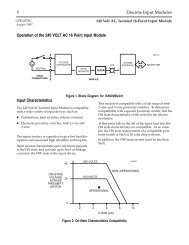
Introduction5. <strong>FIP</strong> BUS INTERFACE UNITThe <strong>FIP</strong> <strong>Bus</strong> <strong>Interface</strong> <strong>Unit</strong> is a small, rugged, intelligent module with a sturdy aluminum housing. The modulehas four status LEDs and a connector for a Hand–Held Programmer.8.2mm (3.25”)46450HHPConnector12.7mm (5.0”)<strong>Alspa</strong> <strong>CE80–20</strong>LEDsThe <strong>Bus</strong> <strong>Interface</strong> <strong>Unit</strong> requires an external source of 24 VDC power.The BIU’s internal power supply provides power for the operation of the BIU itself, and logic power for the I/Omodules connected to it.It mounts on a separate terminal block, to which it and all field wiring are attached. The configuration is storedin non-volatile memory located in the terminal block.The <strong>Bus</strong> <strong>Interface</strong> <strong>Unit</strong> has a replaceable 1A, 5x20 mm 250 VAC slow-blow fuse on the input power lines. Thefuse can be changed without disturbing the wiring of any other modules.5.1. <strong>Bus</strong> <strong>Interface</strong> <strong>Unit</strong> Power SupplyThe 24 VDC power supply in the <strong>Bus</strong> <strong>Interface</strong> <strong>Unit</strong> provides power for the <strong>Bus</strong> <strong>Interface</strong> <strong>Unit</strong> itself and logicpower for all I/O modules that may potentially be installed at that station.External power must be supplied for input and output devices.The BIU power supply is not damaged by either of the following: Reversing input voltage on terminals 1 and 2.Temporary overcurrent conditions on the 6.5 VDC output.ALS 52311 b–en <strong>Alspa</strong> <strong>CE80–20</strong> <strong>FIP</strong> <strong>Bus</strong> <strong>Interface</strong> <strong>Unit</strong> User’s <strong>Manual</strong>Page 1–7
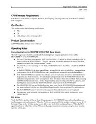
ÎÎÎÎIntroduction5.2. TimingThe <strong>Bus</strong> <strong>Interface</strong> <strong>Unit</strong> provides power to all I/O modules that are installed at the station. I/O module operationis governed by a System Reset signal to ensure controlled operation during the power up and shut down processes.As shown in the timing diagram below, momentary power losses of less than 10 milliseconds do not affect I/Omodule operation; however, longer power losses generate a Reset for all system I/O modules.24VDCNominalInputPower OnVoltageOvershoot5% (max)MomentaryPowerLossVoltageOvershoot5% (max)InputPower Off464566.5V Output200ms(min)95% (min) HoldUpTime10ms(min)200ms(min)HoldUpTime10ms(min)3ms(min)3ms(min)RST5.3. Calculating Input Power Requirements for a <strong>Bus</strong> <strong>Interface</strong> <strong>Unit</strong>The chart below shows typical input power requirements for the 24 VDC power supply.4642212(12.3)TypicalInputPower(Watts)8642ÎÎ(3.4)(5.5)(7.7)(10)0.25 0.5 0.7 1.0Total Backplane Current5(Amps)Page 1–8<strong>Alspa</strong> <strong>CE80–20</strong> <strong>FIP</strong> <strong>Bus</strong> <strong>Interface</strong> <strong>Unit</strong> User’s <strong>Manual</strong>ALS 52311 b–en
IntroductionNoteStart-up surge at full load is 15–50 Amps for 3 milliseconds (maximum).To determine specific system requirements:Determine total output load from typical specifications listed for individual modules.Use the graph above to determine average input power.Divide the input power by the operating source voltage to determine the input current requirements.Use the lowest input voltage to determine the maximum input current.Allow for startup surge current requirements. Startup surge current levels are a function of source impedanceand, therefore, are installation-dependent. Startup surge currents can vary between 25A and 50A forapproximately 3 ms.Allow margins (10% to 20%) for variations.ALS 52311 b–en <strong>Alspa</strong> <strong>CE80–20</strong> <strong>FIP</strong> <strong>Bus</strong> <strong>Interface</strong> <strong>Unit</strong> User’s <strong>Manual</strong>Page 1–9
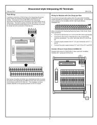
Introduction6. BUS INTERFACE UNIT TERMINAL BLOCKThe <strong>Bus</strong> <strong>Interface</strong> <strong>Unit</strong> provides terminals for power and ground connections. Maximum wire size is 2.10 mm 2AWG No.14.The <strong>Bus</strong> <strong>Interface</strong> <strong>Unit</strong> Terminal Block also has two connectors for attachment to a single or dual <strong>FIP</strong> bus.A connecting cable is provided with each I/O Terminal Block. It is used to connect the <strong>Bus</strong> <strong>Interface</strong> <strong>Unit</strong> TerminalBlock to the first I/O Terminal Block. The same type of cable interconnects subsequent I/O Terminal Blocks. Thecable has molded connectors that are keyed to assure proper orientation.The <strong>Bus</strong> <strong>Interface</strong> <strong>Unit</strong> Terminal Block stores the configuration parameters for the station. The <strong>Bus</strong> <strong>Interface</strong> <strong>Unit</strong>can be removed without removing the wiring or reconfiguring the station.46457<strong>FIP</strong> <strong>Bus</strong>ConnectorsTerminals forpower wiringI/O Terminal BlockConnectorsConnectingCableSpecifications for the <strong>Bus</strong> <strong>Interface</strong> <strong>Unit</strong> terminal block are listed on §7. Wiring information is in chapter 2, § 9.Page 1–10<strong>Alspa</strong> <strong>CE80–20</strong> <strong>FIP</strong> <strong>Bus</strong> <strong>Interface</strong> <strong>Unit</strong> User’s <strong>Manual</strong>ALS 52311 b–en
Introduction7. BUS INTERFACE UNIT FUNCTIONAL SPECIFICATIONS<strong>Bus</strong> <strong>Interface</strong> <strong>Unit</strong>:Reliability :Power–supply :Power Supply InputNominal Rated VoltageVoltage RangePowerInrush CurrentPower Supply OutputMore than 200000 hours operation MTBF, calculated24 VDC18 VDC to 30 VDC16.8 Watts maximum at full load (nominal voltage)15–50 Amps peak, 3 ms maximum (see note)To CPU and communications: 5.0 VDC +/– 3.5%Current required: 0 to 0.42 Amp (0.40 Amp typical)To Hand–Held Programmer: 6.5 VDC +/–5%Current required: 0 to 0.193 Amp maximum with Hand–Held Programmer(0.013 Amp typical)85 mWatt typical, 1.25 Watt maximumTo I/O modules: 6.5 VDC ±5%Holdup Time1.0 Amp maximum10 ms maximum<strong>FIP</strong> Network :Data rate:Protocol:<strong>Bus</strong> Address:<strong>Bus</strong> <strong>Interface</strong> <strong>Unit</strong> TerminalBlock:Power RequirementsReliability1 or 2.5 Mbit/sec (according to board reference number FBI001 or FBI002)<strong>FIP</strong> or World <strong>FIP</strong> (set by built–in dipswitch)0 to 127 decimal (set by built–in dipswitch)16 mA maximumMore than 600 000 hours operation MTBF, calculatedFor information about I/O modules, please see the ALS 52308 <strong>Alspa</strong> <strong>CE80–20</strong> I/O Modules User’s <strong>Manual</strong>.NoteInrush current is installation dependent. See page 1–8, § 5.3..For information about installing I/O modules, see the ALS 52308 <strong>Alspa</strong> <strong>CE80–20</strong> I/O Modules User’s <strong>Manual</strong>.ALS 52311 b–en <strong>Alspa</strong> <strong>CE80–20</strong> <strong>FIP</strong> <strong>Bus</strong> <strong>Interface</strong> <strong>Unit</strong> User’s <strong>Manual</strong>Page 1–11
Introduction8. HAND–HELD PROGRAMMERThe Hand–Held Programmer provides a convenient portable operator interface to the <strong>Bus</strong> <strong>Interface</strong> <strong>Unit</strong> and I/Omodules.Hand–HeldProgrammer46553<strong>FIP</strong> <strong>Bus</strong>The Hand–Held Programmer can be used to monitor, force, and unforce I/O, and to display diagnostics.For more information, please see:Chapter 4, Hand–Held Programmer Functions.The ALS 52202 Hand–Held Programmer for <strong>Alspa</strong> C80–35, C80–25 and C80–05 PLCs User’s <strong>Manual</strong> for basicHHP operating instructions.Page 1–12<strong>Alspa</strong> <strong>CE80–20</strong> <strong>FIP</strong> <strong>Bus</strong> <strong>Interface</strong> <strong>Unit</strong> User’s <strong>Manual</strong>ALS 52311 b–en
Introduction9. ALSPA C80–75 PLC: REQUIREMENTSFor a <strong>FIP</strong> <strong>Bus</strong> <strong>Interface</strong> <strong>Unit</strong> used in an <strong>Alspa</strong> C80–75 PLC system, the following are required:<strong>Alspa</strong> C80–75 CPU version 6 or later.<strong>Alspa</strong> P8–75 programming and configuration software release 6 or later.<strong>Alspa</strong> C80–75 <strong>FIP</strong> <strong>Bus</strong> Controller.ALS 52311 b–en <strong>Alspa</strong> <strong>CE80–20</strong> <strong>FIP</strong> <strong>Bus</strong> <strong>Interface</strong> <strong>Unit</strong> User’s <strong>Manual</strong>Page 1–13
Introduction10. CONFIGURATIONThe <strong>FIP</strong> <strong>Alspa</strong> <strong>CE80–20</strong> I/O Station may be configured in two ways.temporarily with a Hand–Held Programmer.over the <strong>FIP</strong> network.10.1. Hand–Held Programmer ConfigurationA Hand–Held Programmer can be used to temporarily configure I/O modules so I/O data can be monitored, forcedand unforced, before the <strong>Bus</strong> <strong>Interface</strong> <strong>Unit</strong> is operational on the <strong>FIP</strong> network.For more information about this type of configuration see Chapter 4, Hand–Held Programmer Functions.10.2. Network ConfigurationA Network Configuration must be received before the <strong>Bus</strong> <strong>Interface</strong> <strong>Unit</strong> can exchange I/O data on the network.Until it has a valid configuration, the <strong>Bus</strong> <strong>Interface</strong> <strong>Unit</strong> is only capable of identifying itself on the network, thenaccepting the configuration supplied.For more information about this type of configuration see the ALS 52310 <strong>FIP</strong> <strong>Bus</strong> Controller (FBC) for <strong>Alspa</strong>C80–75 PLC User’s <strong>Manual</strong>.Page 1–14<strong>Alspa</strong> <strong>CE80–20</strong> <strong>FIP</strong> <strong>Bus</strong> <strong>Interface</strong> <strong>Unit</strong> User’s <strong>Manual</strong>ALS 52311 b–en
Chapter2InstallationThis chapter describes installation procedures for the <strong>Bus</strong> <strong>Interface</strong> <strong>Unit</strong>.Preinstallation CheckStatic ProtectionRemoving the <strong>Bus</strong> <strong>Interface</strong> <strong>Unit</strong> from the Terminal BlockInstalling the DIN RailInstalling the <strong>Bus</strong> <strong>Interface</strong> <strong>Unit</strong> Terminal Block on the DIN RailInstalling the Cables Between Terminal BlocksSetting the BIU DIP SwitchesInstalling the <strong>Bus</strong> <strong>Interface</strong> <strong>Unit</strong> on the Terminal BlockSystem Wiring GuidelinesSystem GroundingPower Wiring to the <strong>Bus</strong> <strong>Interface</strong> <strong>Unit</strong>Connecting the Communications <strong>Bus</strong>Observing the LEDsRemoving/Replacing the <strong>Bus</strong> <strong>Interface</strong> <strong>Unit</strong> FuseRemoving the <strong>Bus</strong> <strong>Interface</strong> <strong>Unit</strong> Terminal Block from the DIN RailALS 52311 b–en <strong>Alspa</strong> <strong>CE80–20</strong> <strong>FIP</strong> <strong>Bus</strong> <strong>Interface</strong> <strong>Unit</strong> User’s <strong>Manual</strong>Page 2–1
Installation1. PRE–INSTALLATION CHECKCarefully inspect all shipping containers for damage during shipping. If any part of the system is damaged, notifythe carrier immediately. The damaged shipping container should be saved as evidence for inspection by the carrier.As the consignee, it is your responsibility to register a claim with the carrier for damage incurred during shipment.However, Cegelec will fully cooperate with you, should such action be necessary.After unpacking the <strong>Alspa</strong> <strong>CE80–20</strong> modules and other equipment, record all serial numbers. Serial numbers arerequired if you should need to contact Product Service during the warranty period of the equipment.All shipping containers and all packing material should be saved should it be necessary to transport or ship anypart of the system.2. STATIC PROTECTIONThe <strong>Bus</strong> <strong>Interface</strong> <strong>Unit</strong> has CMOS components that are susceptible to static damage. Use proper static handlingtechniques when handling this module.Page 2–2<strong>Alspa</strong> <strong>CE80–20</strong> <strong>FIP</strong> <strong>Bus</strong> <strong>Interface</strong> <strong>Unit</strong> User’s <strong>Manual</strong>ALS 52311 b–en
Installation3. REMOVING THE BUS INTERFACE UNIT FROM THE TERMINALBLOCKThe <strong>Bus</strong> <strong>Interface</strong> <strong>Unit</strong> is shipped pre-installed on the BIU Terminal Block.Remove it to set the BIU DIP switches and to install the connector cable to the first I/O Terminal Block.Do Not Tilt464261. Loosen the <strong>Bus</strong> <strong>Interface</strong> <strong>Unit</strong> retaining screws.CautionBe sure screws are fully disengaged. Attempting to remove the modulewith screw(s) partially engaged may damage it.2. Pull the <strong>Bus</strong> <strong>Interface</strong> <strong>Unit</strong> module straight away from the Terminal Block.CautionDo not tilt the <strong>Bus</strong> <strong>Interface</strong> <strong>Unit</strong> to remove it. Attempting to remove the<strong>Bus</strong> <strong>Interface</strong> <strong>Unit</strong> at an angle may damage it.ALS 52311 b–en <strong>Alspa</strong> <strong>CE80–20</strong> <strong>FIP</strong> <strong>Bus</strong> <strong>Interface</strong> <strong>Unit</strong> User’s <strong>Manual</strong>Page 2–3
Installation4. INSTALLING THE DIN RAILAll <strong>Alspa</strong> <strong>CE80–20</strong> Terminal Blocks must be mounted on a 7.5mm x 35mm DIN rail. The rail must have aconductive (unpainted) finish for proper grounding. For best vibration resistance, the DIN rail should be installedon a panel using screws spaced approximately 15.24 cm (6 inches) apart. When using multiple rail sections, besure they are properly aligned. Mount the DIN rail at least 10.80 cm (4.25 inches) from any wireway or otherobstruction on the wiring side of the <strong>Bus</strong> <strong>Interface</strong> <strong>Unit</strong>. Allow more space if the wiring for I/O modules is verystiff.Drill mounting holes for the BIU Terminal Block as shown below. Allow a small tolerance between the top andbottom of adjacent terminal blocks.14.99 cm (5.90 in) 4645810.80 cm (4.25 in)Wireway11.43 cm (4.50 in)12.70 cm (5.00 in)ClampScrew4.45 cm (1.75 in)10.95 cm (4.31 in)Page 2–4<strong>Alspa</strong> <strong>CE80–20</strong> <strong>FIP</strong> <strong>Bus</strong> <strong>Interface</strong> <strong>Unit</strong> User’s <strong>Manual</strong>ALS 52311 b–en
Installation5. INSTALLING THE BUS INTERFACE UNIT TERMINAL BLOCK ONTHE DIN RAIL1. Tilt the <strong>Bus</strong> <strong>Interface</strong> <strong>Unit</strong> Terminal Block and position it over the rail, as shown below left, catching the railbehind the tabs in the terminal block.2. Pivot the terminal block downward until the spring-loaded DIN rail latches in the terminal block click intoplace.1 246412tabsDINrail3. Tighten the DIN rail clamp screw (see below). Maximum recommended torque is 0.90 Nm to 1.13 Nm (8 in/lbsto 10 in/lbs).46459Tighten4. Secure the terminal block to the panel with 9.525 mm (3/8 inch) No.6 screws (not supplied) through themounting ears.ALS 52311 b–en <strong>Alspa</strong> <strong>CE80–20</strong> <strong>FIP</strong> <strong>Bus</strong> <strong>Interface</strong> <strong>Unit</strong> User’s <strong>Manual</strong>Page 2–5
Installation6. INSTALLING THE CABLES BETWEEN TERMINAL BLOCKSBefore installing modules on their terminal blocks, install the connecting cable(s) between terminal blocks. A shortconnecting cable, as illustrated below, is supplied with each I/O Terminal Block. A set of three connecting cablesis available as renewal part number IC670CBL001. Optional 0.53 meter (21 inch) cable is also available (onlyone longer cable can be used per I/O station).The illustration below shows cable connection between a <strong>Bus</strong> <strong>Interface</strong> <strong>Unit</strong> terminal block and an I/O TerminalBlock. Make connections between I/O Terminal Blocks in the same manner. The connectors are keyed to assureproper installation.After installing the cable, be sure it is firmly seated on both connectors.46498<strong>Bus</strong> <strong>Interface</strong><strong>Unit</strong> TerminalBlockTerminalBlockConnectionCableI/O TerminalBlockConnector for Cableto Next DevicePage 2–6<strong>Alspa</strong> <strong>CE80–20</strong> <strong>FIP</strong> <strong>Bus</strong> <strong>Interface</strong> <strong>Unit</strong> User’s <strong>Manual</strong>ALS 52311 b–en
Installation7. SETTING THE BIU DIP SWITCHESThe DIP switches on the <strong>Bus</strong> <strong>Interface</strong> <strong>Unit</strong> select <strong>FIP</strong> or World <strong>FIP</strong> protocol and establish the BIU’s Station ID(network address).There are two DIP switch packs located inside the main portion of the BIU.46506DIP SwitchesSwitch PositionsSwitch positions are numbered 0 through 7 on the circuit board.Switch Up= 1Switch Down= 0465077 6 5 4 3 2 1 0Switch PositionsSwitch 7 selects <strong>FIP</strong> or World <strong>FIP</strong> protocol, as shown in the table below. Switches 0 through 6 represent a StationID from 0 to 127 (decimal).Switch 7Switches 6 to 07<strong>FIP</strong> = 1 World <strong>FIP</strong> = 06......5......4......3......2......1......0......AddressRepresented1......127ALS 52311 b–en <strong>Alspa</strong> <strong>CE80–20</strong> <strong>FIP</strong> <strong>Bus</strong> <strong>Interface</strong> <strong>Unit</strong> User’s <strong>Manual</strong>Page 2–7
Installation8. INSTALLING THE BUS INTERFACE UNIT ON THE TERMINALBLOCKEnd View46455Cable SlotConnectingCable(cross section)1. Before installing a new <strong>Bus</strong> <strong>Interface</strong> <strong>Unit</strong>, remove the cable slot knockout on the end of the module that will coverthe connecting cable. It can be removed with pliers, or by pressing out from inside the module housing.2. To install <strong>Bus</strong> <strong>Interface</strong> <strong>Unit</strong> on the terminal block, position the module so that the cable slot in the module housingis over the connecting cable. Press the module down firmly.CautionDo not exert excessive force; it may damage the equipment.3. If unusual resistance is met, remove the <strong>Bus</strong> <strong>Interface</strong> <strong>Unit</strong>. If power is applied, DO NOT TOUCH THECONNECTOR PINS! Inspect the Terminal Block, and the connectors on the Terminal Block and on the <strong>Bus</strong><strong>Interface</strong> <strong>Unit</strong>. Remove any obstacles and reinsert the <strong>Bus</strong> <strong>Interface</strong> <strong>Unit</strong>.4. After placing the <strong>Bus</strong> <strong>Interface</strong> <strong>Unit</strong> onto the terminal block, tighten its screws to secure it. Maximumrecommended torque is 1.20 Nm (9 in/lbs).Page 2–8<strong>Alspa</strong> <strong>CE80–20</strong> <strong>FIP</strong> <strong>Bus</strong> <strong>Interface</strong> <strong>Unit</strong> User’s <strong>Manual</strong>ALS 52311 b–en
Installation9. SYSTEM WIRING GUIDELINESFour types of wiring may be encountered in a typical factory installation:1. Power wiring – the plant power distribution, and high power loads such as high horsepower motors. These circuitsmay be rated from tens to thousands of kVA at 220 VAC or higher.2. Control wiring – usually either low voltage DC or 120 VAC of limited energy rating. Examples are wiring tostart/stop switches, contactor coils, and machine limit switches. This is generally the interface level of the CE80–15discrete I/O.3. Analog wiring – transducer outputs and analog control voltages. This is the interface level to CE80–15 I/O analogblocks.4. Communications and signal wiring – the communications network that ties everything together, includingcomputer LANs, MAP, and <strong>FIP</strong> and N80 busses.These four types of wiring should be separated as much as possible to reduce the hazards from insulation failure,miswiring, and interaction (noise) between signals. A typical PLC system may require some mixing of the latterthree types of wiring, particularly in cramped areas inside motor control centers and on control panels.In general, it is acceptable to mix the communications bus cable with the I/O wiring from the blocks, as well asassociated control level wiring. All noise pickup is cumulative, depending on both the spacing between wires, andthe distance span they run together. I/O wires and communications bus cable can be placed randomly in a wiringtrough for lengths of up to 15 meters (50 feet). If wiring is cord–tied (harnessed), do not include the bus cable inthe harness, since binding wires tightly together increases the coupling and mechanical stress that can damage therelatively soft insulation of some serial cable types.Wiring which is external to equipment, and in cable trays, should be separated following NEC practices.Installing Additional SuppressionIt is possible some installations might exceed the surge immunity capabilities of the <strong>Bus</strong> <strong>Interface</strong> <strong>Unit</strong>. This ismost likely in outdoor installations or where the power source is from another building or ground system. It isprudent to provide local transient protection.ALS 52311 b–en <strong>Alspa</strong> <strong>CE80–20</strong> <strong>FIP</strong> <strong>Bus</strong> <strong>Interface</strong> <strong>Unit</strong> User’s <strong>Manual</strong>Page 2–9
Installation10. SYSTEM GROUNDINGAll components of a control system and the devices it controls must be properly grounded. Groundconductors should be connected in a star fashion, with all branches routed to a central earth ground point as shownbelow. This ensures that no ground conductor carries current from any other branch.ProgrammingDeviceEach TerminalBlockMotor Drives andOther ElectricalControlEquipmentMachineryEarthGroundCentralGround PointNOTESignal and powerconnections not shownEach <strong>Alspa</strong> <strong>CE80–20</strong> Terminal Block has a chassis ground terminal for safety and noise protection. This terminalshould be connected to the conductive mounting panel with a 10 cm (4-inch) maximum length of 2.1 mm 2 (AWGNo.14) wire. Use hardware such as star washers to ensure ground integrity.The control panel and enclosure should also be bonded to the plant system ground per code. Inadequate groundingmay compromise system integrity in the presence of power switching transients and surges.Page 2–10<strong>Alspa</strong> <strong>CE80–20</strong> <strong>FIP</strong> <strong>Bus</strong> <strong>Interface</strong> <strong>Unit</strong> User’s <strong>Manual</strong>ALS 52311 b–en
Installation11. POWER WIRING TO THE BUS INTERFACE UNIT1. Connect an appropriate source of 24 VDC (nominal) to the <strong>Bus</strong> <strong>Interface</strong> <strong>Unit</strong> Terminal Block as shown below.Do not apply power yet.46460–24 VDC+3 2 12. Connect the ground terminal to chassis ground using a 2.1 mm 2 (AWG No.14) stranded wire.ALS 52311 b–en <strong>Alspa</strong> <strong>CE80–20</strong> <strong>FIP</strong> <strong>Bus</strong> <strong>Interface</strong> <strong>Unit</strong> User’s <strong>Manual</strong>Page 2–11
Installation12. CONNECTING THE COMMUNICATIONS BUSFor information about cable type, termination, grounding, and connections between devices, please refer to theALS 52310 <strong>FIP</strong> <strong>Bus</strong> Controller (FBC) for <strong>Alspa</strong> C80–75 PLC User’s <strong>Manual</strong>.Attach <strong>FIP</strong> bus cable(s) to the connectors on the front of the <strong>Bus</strong> <strong>Interface</strong> <strong>Unit</strong>. When installed in a single mediaor simplex configuration, either connector may be used.46508Connector for Channel 1Connector for Channel 2Note: If only one <strong>FIP</strong> bus is used, it is recommended that you cover the unused <strong>FIP</strong> bus connector with an anti-staticcap.Pin Assignments for the <strong>FIP</strong> <strong>Bus</strong> ConnectorsThe diagram below shows pin assignments for both <strong>FIP</strong> bus connectors on the front of the BIU.54 93 8D–2176D+46509Page 2–12<strong>Alspa</strong> <strong>CE80–20</strong> <strong>FIP</strong> <strong>Bus</strong> <strong>Interface</strong> <strong>Unit</strong> User’s <strong>Manual</strong>ALS 52311 b–en
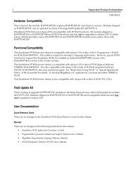
Installation13. OBSERVING THE LEDSWhen power is applied, the LEDs on the BIU indicate operating and communications status.46510C E G E<strong>Alspa</strong> <strong>CE80–20</strong>L E CModule OKRunTransmit Enable Ch. 1Transmit Enable Ch. 2Carrier Detect Ch. 1Carrier Detect Ch. 2+–24 VDCThe top 2 LEDs indicate module health. The bottom 4 LEDs indicate communications activity on the <strong>FIP</strong> bus.Two LEDs are dedicated to each of the two <strong>FIP</strong> channels.MODULE OK –RUN –CARRIER DETECT –TRANSMIT ENABLE –Shows the status of the BIU. This LED blinks during power-up diagnostics and shouldremain on as long as power is applied to the BIU.Shows whether the BIU is actively receiving outputs from the network.A Carrier Detect LED is ON when the BIU is detecting a carrier signal on the <strong>FIP</strong> busattached to that channel.A Transmit Enable LED is ON when the BIU transmits data on the <strong>FIP</strong> bus attachedto that channel.ALS 52311 b–en <strong>Alspa</strong> <strong>CE80–20</strong> <strong>FIP</strong> <strong>Bus</strong> <strong>Interface</strong> <strong>Unit</strong> User’s <strong>Manual</strong>Page 2–13
Installation14. REMOVING/REPLACING THE BUS INTERFACE UNIT FUSEIf all the <strong>Bus</strong> <strong>Interface</strong> <strong>Unit</strong> LEDs go off, it may be necessary to replace its fuse. The fuse can be removed withoutdisturbing any other parts of the station or wiring.To check the fuse, remove power from the station.Fully loosen the retaining screws in the <strong>Bus</strong> <strong>Interface</strong> <strong>Unit</strong> and carefully remove it from the Terminal Block. Donot tilt the module during removal.CautionAvoid touching the exposed wiring on the Terminal Block when removingthe <strong>Bus</strong> <strong>Interface</strong> <strong>Unit</strong>.CautionElectrostatic discharge can damage the module when it is not installed ona Terminal Block. Always observe normal ESD protection practices (forexample, use a grounding strap) when handling an un-installed module.The fuse location is shown below. Visually inspect the fuse to see whether it has blown.46464FuseTo remove the fuse from the holder, carefully pry it upward. Take care not to damage any components in themodule. Place the new fuse in position and press it into the holder.The fuse should be a 1A, 5x20 mm 250 VAC slow-blow type.Reinstall the <strong>Bus</strong> <strong>Interface</strong> <strong>Unit</strong> on the BIU Terminal Block.Page 2–14<strong>Alspa</strong> <strong>CE80–20</strong> <strong>FIP</strong> <strong>Bus</strong> <strong>Interface</strong> <strong>Unit</strong> User’s <strong>Manual</strong>ALS 52311 b–en
Installation15. REMOVING THE BUS INTERFACE UNIT TERMINAL BLOCKFROM THE DIN RAIL1. Loosen the clamp screw.2. Remove the panel-mounting screws.3. Insert a small flat-blade screwdriver into the upper latch and pry it outward. Then, pull up gently on the top ofthe terminal block to disengage the upper latch from the rail.46511LoosenPryUpperlatchPryLowerlatch4. Keep gently pulling the top of the terminal block away from the rail. Insert the screwdriver into the lower latchand pry it outward to free the terminal block.ALS 52311 b–en <strong>Alspa</strong> <strong>CE80–20</strong> <strong>FIP</strong> <strong>Bus</strong> <strong>Interface</strong> <strong>Unit</strong> User’s <strong>Manual</strong>Page 2–15
InstallationPage 2–16<strong>Alspa</strong> <strong>CE80–20</strong> <strong>FIP</strong> <strong>Bus</strong> <strong>Interface</strong> <strong>Unit</strong> User’s <strong>Manual</strong>ALS 52311 b–en
Chapter3OperationThis chapter explains how a <strong>Bus</strong> <strong>Interface</strong> <strong>Unit</strong> interacts with the modules in its I/O Station, how it stores data,and how it exchanges data with the system host.1. OPERATIONThe primary runtime operations of the <strong>Bus</strong> <strong>Interface</strong> <strong>Unit</strong> are to accept data from the <strong>FIP</strong> bus and pass this to thecorresponding output modules and to acquire updated input data for transmission onto the <strong>FIP</strong> bus.If a problem occurs (or is corrected) with any module or circuit, it is included in the status information regularlytransmitted by the <strong>Bus</strong> <strong>Interface</strong> <strong>Unit</strong>. Such module problems do not affect operation of the <strong>Bus</strong> <strong>Interface</strong> <strong>Unit</strong> orits communications on the network.ALS 52311 b–en <strong>Alspa</strong> <strong>CE80–20</strong> <strong>FIP</strong> <strong>Bus</strong> <strong>Interface</strong> <strong>Unit</strong> User’s <strong>Manual</strong>Page 3–1
Operation2. OPERATING MODES OF THE BUS INTERFACE UNITIdleThe <strong>Bus</strong> <strong>Interface</strong> <strong>Unit</strong> can operate in the following modes:Idle ModeReadyReady ModeRun ModeRunHow Communications Affect Operating ModeThe operating mode of the <strong>Bus</strong> <strong>Interface</strong> <strong>Unit</strong> depends on whether or not it is communicating with the <strong>FIP</strong> network.A. If it is communicating with the <strong>FIP</strong> network, the <strong>Bus</strong> <strong>Interface</strong> <strong>Unit</strong> may be commanded by the networkcontroller to operate in Idle, Ready or Run mode.B. If a <strong>FIP</strong> network is not present, the <strong>Bus</strong> <strong>Interface</strong> <strong>Unit</strong> remains in Idle mode at powerup.C. If a <strong>FIP</strong> network is present but communications between the <strong>Bus</strong> <strong>Interface</strong> <strong>Unit</strong> and the network controller havebeen lost, the <strong>Bus</strong> <strong>Interface</strong> <strong>Unit</strong> returns from Run mode back to Ready mode.Page 3–2<strong>Alspa</strong> <strong>CE80–20</strong> <strong>FIP</strong> <strong>Bus</strong> <strong>Interface</strong> <strong>Unit</strong> User’s <strong>Manual</strong>ALS 52311 b–en
Operation3. IDLE MODEIdleReadyRunIn Idle Mode, the <strong>Bus</strong> <strong>Interface</strong> <strong>Unit</strong> can indicate its presence on the <strong>FIP</strong> bus, but itcannot exchange I/O data.The <strong>Bus</strong> <strong>Interface</strong> <strong>Unit</strong> is in Idle Mode after it is powered up but when no configurationor mode change commands have been received from the network. During normaloperation, the <strong>Bus</strong> <strong>Interface</strong> <strong>Unit</strong> is only in Idle mode during the first few seconds afterpowerup. If a <strong>FIP</strong> network controller is not present, the <strong>Bus</strong> <strong>Interface</strong> <strong>Unit</strong> remains inIdle mode.In Idle mode: the <strong>Bus</strong> <strong>Interface</strong> <strong>Unit</strong> scans I/O modules for identification information, input dataand output data.With a <strong>CE80–20</strong> release 1, outputs remain at their programmed default states orhold their last states as configured, unless forced. Any previously forced data. isapplied at powerup or if the equipment was previously in Ready Mode.With a later release of the <strong>CE80–20</strong>, outputs remain off or set to 0. However, I/Odata may be temporarily forced using the HHP in order for a local user to verifythe wiring. Any forced data is therefore lost if the equipment is power–cycled orgoes to Ready Mode. If the equipment comes from Ready Mode, force conditionsare not applied even though they have been stored in FLASH memory, all I/O validator data is set to “invalid,” a Hand–Held Programmer can be used to monitor I/O and input moduleconfigurations if no configuration is available from the network, The <strong>Bus</strong> <strong>Interface</strong> <strong>Unit</strong> can receive a system configuration from the <strong>FIP</strong> network.No forcing via <strong>FIP</strong> messages is permitted.After receiving a system-level configuration the <strong>Bus</strong> <strong>Interface</strong> <strong>Unit</strong> can be commanded (from the network) to goto Ready mode.ALS 52311 b–en <strong>Alspa</strong> <strong>CE80–20</strong> <strong>FIP</strong> <strong>Bus</strong> <strong>Interface</strong> <strong>Unit</strong> User’s <strong>Manual</strong>Page 3–3
Operation4. READY MODEThe <strong>Bus</strong> <strong>Interface</strong> <strong>Unit</strong> goes to Ready mode when a system-level configuration has been received and enabled.IdleReadyRunIn Ready mode: the <strong>Bus</strong> <strong>Interface</strong> <strong>Unit</strong> waits for permission to enter Run mode from the <strong>FIP</strong>network controller, a Hand–Held Programmer can be used to monitor I/O and module configurations,and to force I/O data, configuration can NOT be changed by a Hand–Held Programmer, the <strong>Bus</strong> <strong>Interface</strong> <strong>Unit</strong> scans I/O in accordance with the configuration it receivedfrom the <strong>FIP</strong> network. If it was previously in Idle Mode, forced conditionspreviously stored in FLASH memory are restored and applied.Input data is representative of the values scanned from the I/O modules except ifthey have been defaulted or forced.Outputs are off or set to 0 if the <strong>FIP</strong> BIU was previously in Idle Mode or in a RunMode before receiving a Stop Cmd message from the network.Outputs are frozen if the <strong>FIP</strong> BIU was previously in a Run Mode and output datahas never been received from the network.Outputs are defaulted according to the configuration (default values or frozen) ifthe output data has been received at least once when in a Run Mode, before anetwork loss occured,the <strong>Bus</strong> <strong>Interface</strong> <strong>Unit</strong> accepts forcing information from the network.The <strong>Bus</strong> <strong>Interface</strong> <strong>Unit</strong> can be commanded (from the network) to go to Idle mode for reconfiguration or it maybe commanded to go to Run mode.Page 3–4<strong>Alspa</strong> <strong>CE80–20</strong> <strong>FIP</strong> <strong>Bus</strong> <strong>Interface</strong> <strong>Unit</strong> User’s <strong>Manual</strong>ALS 52311 b–en
Operation5. RUN MODEIn Ready mode, when the <strong>Bus</strong> <strong>Interface</strong> <strong>Unit</strong> receives a command to do so, it goes to Run mode.IdleReadyRunIn Run Locked Mode: all configured modules are operational, data is communicated to and from the <strong>FIP</strong> network, the <strong>Bus</strong> <strong>Interface</strong> <strong>Unit</strong> scans I/O in accordance with the configuration it receivedfrom the <strong>FIP</strong> network, the <strong>Bus</strong> <strong>Interface</strong> <strong>Unit</strong> generates and observes validators, the <strong>Bus</strong> <strong>Interface</strong> <strong>Unit</strong> can communicate fully on the <strong>FIP</strong> network, configuration changes are not permitted, HHP use is not permitted in Run Locked Mode.The mode changes back to Ready upon command from the network or if the <strong>Bus</strong><strong>Interface</strong> <strong>Unit</strong> loses communications.Run Unlocked ModeRun Unlocked mode is the same as described above, except that the <strong>Bus</strong> <strong>Interface</strong> <strong>Unit</strong> does not check refreshmentand promptness status in Run Unlocked mode.HHP is usable in Run Unlocked Mode as it was in Ready Mode.ALS 52311 b–en <strong>Alspa</strong> <strong>CE80–20</strong> <strong>FIP</strong> <strong>Bus</strong> <strong>Interface</strong> <strong>Unit</strong> User’s <strong>Manual</strong>Page 3–5
Operation6. I/O DATAThe <strong>Bus</strong> <strong>Interface</strong> <strong>Unit</strong> stores I/O data, as well as additional data representing forced conditions and “validator”status, in separate memory areas.Data DescriptionData Type Displayed onHHP<strong>Alspa</strong> C80–75 PLC DataTypediscrete input states I %Idiscrete output states Q %Qanalog input values AI %AIanalog output values AQ %AQdiscrete input validatorsoutput validatorsanalog input validatorsanalog output validatorsFault/No Fault ContactsIn the <strong>Bus</strong> <strong>Interface</strong> <strong>Unit</strong>, the I/O state and validator tables contain the input and output data.If the <strong>Bus</strong> <strong>Interface</strong> <strong>Unit</strong> detects a problem while reading a module’s inputs, it sets to ”invalid” all InputValidators for that module.If output validators for outputs received from the network are “invalid”, those outputs will be defaulted or holdlast state.Displaying Data with a Hand–Held ProgrammerThe Hand–Held Programmer can read data directly from the <strong>Bus</strong> <strong>Interface</strong> <strong>Unit</strong>. If the <strong>Bus</strong> <strong>Interface</strong> <strong>Unit</strong> is in Idle,Ready mode or Run Unlocked mode, the Hand–Held Programmer can also force the states of I/O data.Page 3–6<strong>Alspa</strong> <strong>CE80–20</strong> <strong>FIP</strong> <strong>Bus</strong> <strong>Interface</strong> <strong>Unit</strong> User’s <strong>Manual</strong>ALS 52311 b–en
Operation6.1. Discrete InputsThe <strong>Bus</strong> <strong>Interface</strong> <strong>Unit</strong> has the following discrete input tables:IIVIFIFVdiscrete input statesdiscrete input validatorsforce applied: discrete inputsforce applied: discrete input validatorsThe <strong>Bus</strong> <strong>Interface</strong> <strong>Unit</strong> processes input data as described below.1. The <strong>Bus</strong> <strong>Interface</strong> <strong>Unit</strong> scans input modules in the I/O Nest and then places discrete input data in its discreteinput table.Example:The <strong>Bus</strong> <strong>Interface</strong> <strong>Unit</strong> reads the inputs configured to use I0001 to I0008 during its inputscan. It places the data into its discrete input table:I00011 0 0 1 0 1 0 0I00082. If the <strong>Bus</strong> <strong>Interface</strong> <strong>Unit</strong> detects a module fault while reading the input data, it defaults all inputs for thatmodule to the configured off or last state, and marks them as “invalid” by setting the input validator (IV)locations associated with those inputs.Example:If the module supplying inputs I0001 to I0008 is configured to default inputs OFF, andthe module is subsequently removed, the <strong>Bus</strong> <strong>Interface</strong> <strong>Unit</strong> sets its inputs OFF andalso sets the corresponding input validator data:I00010 0 0 0 0 0 0 0I0008Inputs set to OFFIV00011 1 1 1 1 1 1 1IV0008Input validatorsset to “invalid”3. If the <strong>Bus</strong> <strong>Interface</strong> <strong>Unit</strong> is in any Idle or Ready mode, inputs may be forced. The <strong>Bus</strong> <strong>Interface</strong> <strong>Unit</strong> sets thecorresponding inputs in the input table. When a force is removed, the input table displays the normal datafollowing the next I/O scan.ALS 52311 b–en <strong>Alspa</strong> <strong>CE80–20</strong> <strong>FIP</strong> <strong>Bus</strong> <strong>Interface</strong> <strong>Unit</strong> User’s <strong>Manual</strong>Page 3–7
OperationExample:The HHP is used to force input I0008 to 1.I00011 0 0 1 0 1 0 0I0008Input Data before forcing1 0 0 1 0 1 0 1Input Data after forcing4. When you force the state of a point, the <strong>Bus</strong> <strong>Interface</strong> <strong>Unit</strong> forces the corresponding validator (IVF) to 0 (valid).Input Data Sent on the <strong>Bus</strong>The <strong>Bus</strong> <strong>Interface</strong> <strong>Unit</strong> treats the data acquired from each Input or Input/Output module as an “applicationvariable.” It combines these (input) application variables into one or more Communications Variables (COMVs).It periodically transmits these COMVs on the <strong>FIP</strong> Network.<strong>FIP</strong> NetworkCommunicationsVariableApplicationVariableApplicationVariableApplicationVariableValidityQualifiersValidityQualifiersValidityQualifiers<strong>Alspa</strong> <strong>CE80–20</strong>I/O ModulesInputModuleInputModuleInputModule46512The <strong>Bus</strong> <strong>Interface</strong> <strong>Unit</strong> honors requests for input data even when the data is invalid (e.g. the corresponding inputmodule has been removed). By monitoring the validity data, the host can know whether the data it receives fromthe <strong>Bus</strong> <strong>Interface</strong> <strong>Unit</strong> is real or defaulted input data.Page 3–8<strong>Alspa</strong> <strong>CE80–20</strong> <strong>FIP</strong> <strong>Bus</strong> <strong>Interface</strong> <strong>Unit</strong> User’s <strong>Manual</strong>ALS 52311 b–en
Operation6.2. Discrete OutputsThe <strong>Bus</strong> <strong>Interface</strong> <strong>Unit</strong> has the following discrete output tables:QQVQFQVFdiscrete output statesdiscrete output validatorsforce applied: discrete outputsforce applied: discrete output validatorsThe <strong>Bus</strong> <strong>Interface</strong> <strong>Unit</strong> processes output data as described below.1. The <strong>Bus</strong> <strong>Interface</strong> <strong>Unit</strong> periodically receives Communications Variables (COMVs) containing discrete outputdata. The content of these COMVs may depend on the system host. In an <strong>Alspa</strong> 8000 PLC system, discreteoutput COMVs consist of Q data (application variables) and QV data (validity qualifiers).<strong>FIP</strong> NetworkCommunicationsVariableApplicationVariableApplicationVariableApplicationVariableValidityQualifiersValidityQualifiersValidityQualifiers<strong>Alspa</strong> <strong>CE80–20</strong>Output ModulesOutputModuleOutputModuleOutputModule465132. The <strong>Bus</strong> <strong>Interface</strong> <strong>Unit</strong> places the output data into its discrete output table.Example:The <strong>Bus</strong> <strong>Interface</strong> <strong>Unit</strong> receives output data from the host, including outputs Q0009 toQ0016. It places those outputs into its discrete output table as illustrated below:Q00090 0 1 1 0 1 1 1Q00163. The <strong>Bus</strong> <strong>Interface</strong> <strong>Unit</strong> checks the corresponding validity data to determine whether or not the output datareceived from the host is valid.The specific way output validators are set may depend on the system host. In an <strong>Alspa</strong> C80–75 PLC system,the PLC bus controller sets the output validators to invalid if it doesn’t receive output communications fromthe CPU. The <strong>Bus</strong> <strong>Interface</strong> <strong>Unit</strong> also sets output validators if it doesn’t receive output data from the <strong>FIP</strong> busduring a specified period of time.If an output validator is set to invalid, the <strong>Bus</strong> <strong>Interface</strong> <strong>Unit</strong> discards the actual output data and sets thecorresponding output to the configured default states or holds their last state (as configured).ALS 52311 b–en <strong>Alspa</strong> <strong>CE80–20</strong> <strong>FIP</strong> <strong>Bus</strong> <strong>Interface</strong> <strong>Unit</strong> User’s <strong>Manual</strong>Page 3–9
OperationExample:If the host stopped sending outputs, the <strong>Bus</strong> <strong>Interface</strong> <strong>Unit</strong> could set all discrete outputs tooff (as shown here) or to their last state, and also set the corresponding output validatordata:Q00090 0 0 0 0 0 0 0QV00091 1 1 1 1 1 1 1Q0016QV0016Outputs set to OFFOutput validatorsset to “invalid”4. The <strong>Bus</strong> <strong>Interface</strong> <strong>Unit</strong> passes outputs (either actual outputs or outputs that are defaulted) to the outputmodules. The output scan occurs after the input scan.5. If the <strong>Bus</strong> <strong>Interface</strong> <strong>Unit</strong> is in any Idle or Ready mode, outputs may be forced from the HHP. The <strong>Bus</strong> <strong>Interface</strong><strong>Unit</strong> sets the corresponding outputs in the output force (QF) table. The forced state becomes the state of theoutput circuit.Example:The HHP is used to force output Q0012 to 0.Q00090 0 1 1 0 1 1 1Q0016Output Data before forcing1 1 1 0 0 1 0 1Output Data after forcingWhen a force is removed, the data in the corresponding I/O table displays the normal data following the nextI/O scan. Outputs retain an up-to-date processed value, which is used whenever the forced value is removed.Page 3–10<strong>Alspa</strong> <strong>CE80–20</strong> <strong>FIP</strong> <strong>Bus</strong> <strong>Interface</strong> <strong>Unit</strong> User’s <strong>Manual</strong>ALS 52311 b–en
Operation6.3. Analog InputsThe <strong>Bus</strong> <strong>Interface</strong> <strong>Unit</strong> has the following analog input tables.AIAIVAIFAIVFanalog input valuesanalog input validatorsforce applied: analog inputsforce applied: analog input validatorsThe <strong>Bus</strong> <strong>Interface</strong> <strong>Unit</strong> processes analog input data as described below (analog input modules filter data locally,so the data is already filtered when the <strong>Bus</strong> <strong>Interface</strong> <strong>Unit</strong> reads it.)1. The <strong>Bus</strong> <strong>Interface</strong> <strong>Unit</strong> scans analog input modules in the I/O Nest and places analog input data in its analoginput table.Example:During the analog input scan, the <strong>Bus</strong> <strong>Interface</strong> <strong>Unit</strong> reads the inputs configured to useAI001 through AI004. It places the inputs into its analog input table:AI001AI002AI003AI00457143163853688411412. If the <strong>Bus</strong> <strong>Interface</strong> <strong>Unit</strong> detects a module fault while reading the input data, it defaults all inputs associatedwith that module to their default/hold last state values, and marks them as “invalid” by setting to 8Xh the AIVlocations associated with those inputs (80h: invalid, X: specific fault involving the invalidity).Example:If the module supplying inputs AI001 to AI004 were removed and the module wereconfigured for Hold Last State, the <strong>Bus</strong> <strong>Interface</strong> <strong>Unit</strong> would hold the inputs for thatmodule to their last values, and set the corresponding validators to invalid (8Xh).AI001AI002Analog Input Data5714316385Validator StatusAIV001 80h8Xh = invalidAIV002 80hAI00336884AIV00380hAI0041141AIV00480h3. Analog inputs may be forced. The <strong>Bus</strong> <strong>Interface</strong> <strong>Unit</strong> sets the corresponding inputs in the analog input table,which also contains the current states of unforced inputs. When a force is removed, the input table displaysthe normal data following the next I/O scan.ALS 52311 b–en <strong>Alspa</strong> <strong>CE80–20</strong> <strong>FIP</strong> <strong>Bus</strong> <strong>Interface</strong> <strong>Unit</strong> User’s <strong>Manual</strong>Page 3–11
OperationExample:The HHP is used to force analog input AI002 to a different value. The forced valuereplaces the actual value in the analog input table:Analog Input Databefore forcingAnalog Input Dataafter forcingAI001AI002AI003AI0045714316385368841141571435003688411414. When you force the value of a channel, the <strong>Bus</strong> <strong>Interface</strong> <strong>Unit</strong> also forces the corresponding validator (AIVF)to 0.Example:When the HHP forces input AI002 its input validator is also forced.Analog Input Databefore forcingValidator StatusAnalog Input Dataafter forcingValidator Statusafter forcingAI001AI002AI003AI004571431638536884114180h84h82h81h5714350036884114180h082h81hAnalog Input Data Sent on the <strong>Bus</strong>The <strong>Bus</strong> <strong>Interface</strong> <strong>Unit</strong> combines analog input data into one or more Communications Variables (COMVs). Itperiodically transmits these COMVs on the Network.<strong>FIP</strong> NetworkCommunicationsVariableApplicationVariableApplicationVariableApplicationVariableValidityQualifiersValidityQualifiersValidityQualifiers<strong>Alspa</strong> <strong>CE80–20</strong>Input ModulesInputModuleInputModuleInputModules46512The <strong>Bus</strong> <strong>Interface</strong> <strong>Unit</strong> honors requests for input data even when the data is invalid (e.g. the corresponding inputmodule has been removed). By monitoring the validity data, the host can know whether the data it receives fromthe <strong>Bus</strong> <strong>Interface</strong> <strong>Unit</strong> is real or defaulted input data.Page 3–12<strong>Alspa</strong> <strong>CE80–20</strong> <strong>FIP</strong> <strong>Bus</strong> <strong>Interface</strong> <strong>Unit</strong> User’s <strong>Manual</strong>ALS 52311 b–en
Operation6.4. Analog OutputsThe <strong>Bus</strong> <strong>Interface</strong> <strong>Unit</strong> has the following analog output tables.AQAQVAQFAQVFanalog output valuesanalog output validatorsforce applied: analog outputsforce applied: analog output validatorsThe <strong>Bus</strong> <strong>Interface</strong> <strong>Unit</strong> processes analog output data as described below.1. The <strong>Bus</strong> <strong>Interface</strong> <strong>Unit</strong> periodically receives Communications Variables (COMVs) containing analog outputdata.The content of these COMVs may depend on the system host. In an <strong>Alspa</strong> 8000 PLC system, analog outputCOMVs consist of AQ data (application variables) and AQV data (validity qualifiers).<strong>FIP</strong> NetworkCommunicationsVariableApplicationVariableApplicationVariableApplicationVariableValidityQualifiersValidityQualifiersValidityQualifiers<strong>Alspa</strong> <strong>CE80–20</strong>Output ModulesOutputModuleOutputModuleOutputModule465132. The <strong>Bus</strong> <strong>Interface</strong> <strong>Unit</strong> places the output data into its Analog Output table.Example:The <strong>Bus</strong> <strong>Interface</strong> <strong>Unit</strong> receives output data from the host, including outputs AQ005through AQ008. It places those outputs into its AQ data table as illustrated below:AQ005AQ006AQ007AQ00811472106933. The <strong>Bus</strong> <strong>Interface</strong> <strong>Unit</strong> checks the corresponding validity data to determine whether or not the output datareceived from the host is valid.The specific way output validators are set may depend on the system host. In an <strong>Alspa</strong> C80–75 PLC system,for example, the PLC bus controller sets the output validators to invalid if it doesn’t receive outputcommunications from the CPU. The <strong>Bus</strong> <strong>Interface</strong> <strong>Unit</strong> also sets output validators if it doesn’t receive outputdata from the <strong>FIP</strong> bus during a specified period of time.ALS 52311 b–en <strong>Alspa</strong> <strong>CE80–20</strong> <strong>FIP</strong> <strong>Bus</strong> <strong>Interface</strong> <strong>Unit</strong> User’s <strong>Manual</strong>Page 3–13
Operation4. If output validators are set to invalid the <strong>Bus</strong> <strong>Interface</strong> <strong>Unit</strong> defaults the output data to a configured value orholds its last state, as configured.Example:If the host stopped sending outputs, the <strong>Bus</strong> <strong>Interface</strong> <strong>Unit</strong> would default or hold allanalog outputs at their last values and also set the corresponding output validator data:Analog Output DataAQ005 114AQ00672AQ007 106AQ00893Validator StatusAQV005 80h 80h = invalidAQV006 80hAQV007 80hAQV008 80hPage 3–14<strong>Alspa</strong> <strong>CE80–20</strong> <strong>FIP</strong> <strong>Bus</strong> <strong>Interface</strong> <strong>Unit</strong> User’s <strong>Manual</strong>ALS 52311 b–en
Operation7. DIAGNOSTICSThe <strong>Bus</strong> <strong>Interface</strong> <strong>Unit</strong> provides status information for each I/O module in the I/O Nest. If a fault occurs, the faultis logged and the corresponding fault contact is activated. It remains activated only while the fault is in effect. Afterthe condition that caused the fault is corrected, the <strong>Bus</strong> <strong>Interface</strong> <strong>Unit</strong> deactivates the corresponding fault contactand resumes normal operation of the affected circuit(s).7.1. Status Data Transmitted by the <strong>Bus</strong> <strong>Interface</strong> <strong>Unit</strong>The <strong>Bus</strong> <strong>Interface</strong> <strong>Unit</strong> periodically transmits status information as a separate Communications Variable.<strong>Alspa</strong> <strong>CE80–20</strong>I/O Modules46514<strong>FIP</strong> NetworkOutputModuleOutputModuleStatusCommunicationVariableModules’StatusInputModuleInputModuleIf a problem occurs (or is corrected) with any module or circuit, it is included in this status information. Suchmodule problems do not affect the operation of the <strong>Bus</strong> <strong>Interface</strong> <strong>Unit</strong> or its communications on the network.7.2. I/O module validatorsThe <strong>FIP</strong> <strong>Bus</strong> <strong>Interface</strong> <strong>Unit</strong> handles the processing of the I/O modules validators. Validators are set :when a slot is configured for a specific module but no module is present,when the module present does not match the one defined in the configuration,when the module is faulted,when the module or the <strong>FIP</strong> BIU reports a user fault for that slot.Dumb and smart I/O modules provide diagnostic data to the <strong>FIP</strong> BIU.The validators always have the same format which is one bit per point for discrete I/O and one byte per channelfor analog and smart modules.ALS 52311 b–en <strong>Alspa</strong> <strong>CE80–20</strong> <strong>FIP</strong> <strong>Bus</strong> <strong>Interface</strong> <strong>Unit</strong> User’s <strong>Manual</strong>Page 3–15
Operation7.2.1. Discrete and analog modulesV:0 : valid1: invalidV000VDiscrete input or output validatorb7 b6 b5 b4 b3 b2 b1 b0V 0 0 0 0 0 0 0 Analog input or output validatorIn the special case of the 8 analog input module, additional data may be reported in the validator to show specificuser faults or alarms: b0 : Low alarm * , b1: High alarm * , b2 : Under–range, b3 : Over–range, b4 : Open–wire.* : with alarm bits, the validity bit (b7) is not affected.7.2.2. Smart modulesb7 b6 b5 b4 b3 b2 b1 b0V x x x x x x x Smart analog input or output validator0 : valid1: invalidSmart I/O modules may report extra diagnostic data. The <strong>FIP</strong> BIU may be configured to decode this module’s datato set up specific bits in the module’s validators.The Network configuration provides the following parameters :the number of user faults to report (corresponding to one bit of the validator),the validator bit rank, which is the position of the bit to set/clear in the validator,the fault bit value which indicates if the validator bit has to be set or cleared, and for each channel : the byte offset within the diagnostic bytes returned by the I/O module, the bit position of the fault in the byte previously selected.The Network Configuration provides also parameters meant to report Alarm bits in the validators. In that case thevalidity bit (b7) is not affected.=> Refer to ALS 52308 <strong>CE80–20</strong> I/O Modules User’s <strong>Manual</strong> for explanations regarding the diagnostic bitsreported by the smart modules.Page 3–16<strong>Alspa</strong> <strong>CE80–20</strong> <strong>FIP</strong> <strong>Bus</strong> <strong>Interface</strong> <strong>Unit</strong> User’s <strong>Manual</strong>ALS 52311 b–en
Operation7.2.3. <strong>Bus</strong> <strong>Interface</strong> <strong>Unit</strong> Status Data FormatThe format of the status (IOSTAT) COMV sent by the <strong>Bus</strong> <strong>Interface</strong> <strong>Unit</strong> is shown below.Offset(Byte No.)ContentDescription012 (constant)0 (constant)<strong>FIP</strong> <strong>Bus</strong> <strong>Interface</strong> <strong>Unit</strong> Identification2, 3 0 to 65535 Network configuration Version number4 00 = Non-operational fault01 = Operational: Idle02 = Operational: Ready03 = Operational: Running Locked04 = Operational: Running UnlockedCurrent Operating mode of the <strong>FIP</strong> BIU.This field is updated as long as the <strong>FIP</strong> BIU is Operational.5 Bit Status Bits0 Loss of <strong>FIP</strong> Status bits Set when status bits (refreshment and promptness) associatedwith any consumed COMVs are invalid. Cleared when allstatus bits are valid.1 Slow scanning mode Set when BIU is in slow scanning mode because at least oneanalog I/O module has been scheduled to have its inputs oroutputs scanned over several cycles.2 I/O are currently forced Set when any points are forced whatever using the HHP or anetwork message.3 – 6 reserved7 Ready mode disconnected Set if the I/O nest is in READY mode following on a networkfault or disconnection. Cleared as soon as a command isreceived regardless of whether or not the command is valid.Loss of more than three consecutive EOC in synchronousmode or failure to consume at least one COMV are treated asnetwork failures.6 Bit Fault Type0 Blocking (fatal) fault Always 0.1 Non-blocking fault Set when any Scanner or I/O faults are detected. Clearedotherwise.2 Scanner blocking fault Always 0.3 Scanner non-blocking fault Set when the Scanning Module Fault (byte 8) is not 0.4 I/O module fault Set when any I/O modules have the status: empty, discordant,user-fault or fault.5–7 reserved7 0 Unused.ALS 52311 b–en <strong>Alspa</strong> <strong>CE80–20</strong> <strong>FIP</strong> <strong>Bus</strong> <strong>Interface</strong> <strong>Unit</strong> User’s <strong>Manual</strong>Page 3–17
OperationOffset(Byte No.)ContentDescription8 Bits Scanning module faults0,1 reserved2 Store operation failure Set when an error occurs during a non-volatile memory storeoperation. Cleared by a successful store operation.3 Watchdog expired * Set when a watchdog fault occurs after a transition to Idlemode. Cleared when a CONFIG_ENABLE command isreceived.This bit remains set until the next time the <strong>FIP</strong> BIU iscommanded to go to Ready or Run mode.4 Timing Fault Set when an RTC interrupt has taken more than 10 ms toexecute. Once it is set, it stays set until a new valid commandis received.5 reserved6 Loss of <strong>FIP</strong> media redundancy Set when a redundancy error has been detected. Cleared whenthe redundancy is restored.7 reserved9 8 (constant) Number of I/O slots.10, ...,18 I/O Slot status (repeated for each I/O module). May have the following values for a <strong>FIP</strong> BIUapplication:01 = empty The configuration is installed, but there is nothing present inthe slot even though that slot has been configured.02 = discordant The configuration is installed, but the module in the slot doesnot match the configuration.04 = operational Configuration installed, correct module is present in slot andit is fully functional.05 = user fault The configuration is installed, module is operational but themodule reports a user fault.ff = fault (255 decimal)Configuration is installed, correct module is present in slot,but it is not operating.* If the watchdog timer expires, the <strong>Bus</strong> <strong>Interface</strong> <strong>Unit</strong> goes to Idle mode and sets the Watchdog Expired bit in. This bit remains set until the next time the <strong>FIP</strong> <strong>Bus</strong> <strong>Interface</strong> <strong>Unit</strong> is commanded togo to Ready or Run mode.Page 3–18<strong>Alspa</strong> <strong>CE80–20</strong> <strong>FIP</strong> <strong>Bus</strong> <strong>Interface</strong> <strong>Unit</strong> User’s <strong>Manual</strong>ALS 52311 b–en
Chapter4Hand–Held Programmer FunctionsThis chapter explains how to use a Hand–Held Programmer with a <strong>FIP</strong> <strong>Bus</strong> <strong>Interface</strong> <strong>Unit</strong>:Using the Hand–Held Programmer, HHP Displays, Menu Overview, Moving from Screen to Screen,Displaying and Editing Configuration Data, Displaying the <strong>Bus</strong> <strong>Interface</strong> <strong>Unit</strong> Configuration, Configuring I/O Modules,Reading a Module Configuration,Configuring an Empty Slot,Configuring a Discrete Input Module,Configuring a Discrete Output Module,Configuring an Analog Input Module,Configuring an Analog Output Module,Monitoring and Forcing I/O Data, Looking at I/O Data, Changing the Data Display Format: Binary, Hex, Decimal, Forcing and Unforcing Data,Displaying and Clearing Faults, Displaying Faults, Clearing Faults.For Additional Information, Also See:For additional information on basic Hand–Held Programmer functions, please refer to the ALS 52202 Hand–HeldProgrammer for <strong>Alspa</strong> C80–35, C80–25 and C80–05 PLCs User’s <strong>Manual</strong>.ALS 52311 b–en <strong>Alspa</strong> <strong>CE80–20</strong> <strong>FIP</strong> <strong>Bus</strong> <strong>Interface</strong> <strong>Unit</strong> User’s <strong>Manual</strong>Page 4–1
Hand–Held Programmer Functions1. USING THE HAND–HELD PROGRAMMERAttach the Hand–Held Programmer to the MONITOR connector on the BIU.46565<strong>Bus</strong> <strong>Interface</strong> <strong>Unit</strong>Hand–HeldProgrammer1.1. HHP DisplaysThe content of the HHP display screens varies according to the type of device it is connected to (for example, thescreens for a <strong>FIP</strong> BIU are different from the screens for a Remote I/O Scanner).This is the HHP’s main menu when it is connected to a <strong>FIP</strong> <strong>Bus</strong> <strong>Interface</strong> <strong>Unit</strong>:1 Monitor I/O2 ConfigurationPage 4–2<strong>Alspa</strong> <strong>CE80–20</strong> <strong>FIP</strong> <strong>Bus</strong> <strong>Interface</strong> <strong>Unit</strong> User’s <strong>Manual</strong>ALS 52311 b–en
Hand–Held Programmer Functions1.2. Menu OverviewThe illustration below shows the primary Hand–Held Programmer menus that are accessed from the <strong>FIP</strong> BIU mainmenu.1 Monitor I/O2 Configuration465641 <strong>FIP</strong> Config2 Module Config1 Monitor I/O2 FaultsR0:S1 I:16I00001– I00016<strong>FIP</strong> ID:9AI000011B1 First 16 Flts2 Last 16 FltsR0:S2 EMPTY <strong>FIP</strong> Protocol:WORLD <strong>FIP</strong>Q000010BSlot 1 Fault#01CONFIG MISMATCH<strong>FIP</strong> Transf rate :1MHz1 FORCE2 UNFORCE<strong>FIP</strong> Time Slot :250Enter value :_Config Version :0Config Error :0Firmware Rev ;2.0<strong>FIP</strong> FDM Lib Rev :4.3Board Number :FBI001Moving from Screen to ScreenTo move between displays, use the following keys:press the Right Arrow key to go “down.”press the Left Arrow key to go “up.”press the Up Arrow key to go up one branch.Advancing past the last screen in a set returns you to the top.ALS 52311 b–en <strong>Alspa</strong> <strong>CE80–20</strong> <strong>FIP</strong> <strong>Bus</strong> <strong>Interface</strong> <strong>Unit</strong> User’s <strong>Manual</strong>Page 4–3
Hand–Held Programmer Functions2. DISPLAYING AND EDITING CONFIGURATION DATAFrom the main menu, press the 2 key (Configuration). This menu appears:1 <strong>FIP</strong> Config2 Module ConfigFrom this menu, you can:Press the 1 key to display, but not change, the <strong>FIP</strong> <strong>Bus</strong> <strong>Interface</strong> <strong>Unit</strong> configuration.Press the 2 key to enter, display, and edit I/O module configurations.Page 4–4<strong>Alspa</strong> <strong>CE80–20</strong> <strong>FIP</strong> <strong>Bus</strong> <strong>Interface</strong> <strong>Unit</strong> User’s <strong>Manual</strong>ALS 52311 b–en
Hand–Held Programmer Functions3. DISPLAYING THE BUS INTERFACE UNIT CONFIGURATIONWhen you press the number 1 key from the Configuration menu, the first BIU configuration display screen appears.The first screen shows the <strong>FIP</strong> Station ID (14 in this example).<strong>FIP</strong> ID14Press the RIGHT ARROW key to display other Remote I/O Scanner parameters. Parameters appear in this order:DISPLAY VALUES DESCRIPTION<strong>FIP</strong> ID : 0, ..., 127 Current Remote I/O Scanner <strong>FIP</strong> subscriber number. Selectedby built–in dipswitch.<strong>FIP</strong> Protocol : <strong>FIP</strong> or WORLD <strong>FIP</strong> Current <strong>FIP</strong> network protocol selected by built–in dipswitch.<strong>FIP</strong> Transf rate : ** 1 MHz or 2.5 MHz <strong>FIP</strong> data transfert rate. Depends on board used.<strong>FIP</strong> Time Slot : ** 250 or 200 <strong>FIP</strong> network Time Slot. Depends on board used and data transfertrate.Config Version : * 0000, ..., FFFFh Version number of the current configuration installed. A nullvalue means no configuration installed or invalid configuration.Config Error : * 0000, ..., 60000 Error code corresponding to a list of identified errors listed in aspecific release document.Firmware Rev : * 2.00 < vvv < x.yz Remote I/O Scanner firmware revision number.<strong>FIP</strong> FDM Lib Rev : * 4.3 < w.w < a.b <strong>FIP</strong> Device Manager library revision number.Board Number : * FBI001 or FBI002 Remote I/O Scanner board revision number (1 MHz or 2.5MHzboard).ALS 52311 b–en <strong>Alspa</strong> <strong>CE80–20</strong> <strong>FIP</strong> <strong>Bus</strong> <strong>Interface</strong> <strong>Unit</strong> User’s <strong>Manual</strong>Page 4–5
Hand–Held Programmer Functions4. CONFIGURING I/O MODULESWhen you press the 2 key from the Configuration menu, the first module configuration screen appears.At first, the module configuration screen looks like this:RacknumberSlotnumberModule type andnumber of pointsR0:S1 I:16I00001– I00016Assignedreferences846476BIU076543210BIU12345678The Rack Number is always 0.The Slot Number refers to the location of the module in the station, relative to the <strong>Bus</strong> <strong>Interface</strong> <strong>Unit</strong>. See theillustration below.Page 4–6<strong>Alspa</strong> <strong>CE80–20</strong> <strong>FIP</strong> <strong>Bus</strong> <strong>Interface</strong> <strong>Unit</strong> User’s <strong>Manual</strong>ALS 52311 b–en
Hand–Held Programmer FunctionsFrom this screen, you can:Display other modules using the Right Arrow and Left Arrow key.Delete the currently-displayed module by pressing the DEL key.Configure the currently-displayed module by pressing the ENT key.To edit the module’s configuration, press F4 (zoom). Refer to the module configuration instructions on thefollowing pages for more information.4.1. Reading a Module ConfigurationIf there is an unconfigured module present in the slot, press the READ key to read its configuration. You can editthis configuration as described on the following pages.4.2. Configuring an Empty SlotIf there is no module present in the slot, the screen displays:R0:S1EMPTYIf you want to enter a configuration, press the INS key. This screen will appear:R0:S1 I/O Type ?Generic I/O1. Press the +/– key to select either Generic I/O, Special I/O or Smart I/O (see the list below). Then press theENT key..R0:S1 I/O Type ?Special I/OR0:S1 I/O Type ?Smart I/O2. The screen prompts: R0:S1 Mod Type ? Use the +/– key to go through the module names listedbelow.ALS 52311 b–en <strong>Alspa</strong> <strong>CE80–20</strong> <strong>FIP</strong> <strong>Bus</strong> <strong>Interface</strong> <strong>Unit</strong> User’s <strong>Manual</strong>Page 4–7
Hand–Held Programmer FunctionsGeneric I/OModulesDiscrete Input 8 IC670 MDL233Discrete Input 16 IC670 MDL240MDL241MDL640MDL641MDL642MDL643MDL644Discrete Output 8 IC670 MDL331MDL730MDL930Discrete Output 16 IC670 MDL330MDL740MDL742Special I/OAnalog 8 Current Input IC670 ALG230Analog 4 Current Output IC670 ALG320Smart I/OAnalog 16 Current Input IC670 ALG240Analog 4 RTD Input IC670 ALG620Analog 8 THM Input IC670 ALG630Analog 8 Current Output IC670 ALG330ModulesModules3. When the correct module name appears, press the ENT key. Complete the module configuration as describedon the following pages. to configure a Discrete Input Module, see page 4–8, § 4.3. to configure a Discrete Output Module, see page 4–10, § 4.4. to configure an Analog Input Module, see page 4–11, § 4.5. to configure an Analog Output Module, see page 4–15, § 4.6.4.3. Configuring a Discrete Input ModuleA discrete input module has two configurable parameters:Fault ReportingSelection of either Hold Last State or Default to Zero for all the module’s inputs.4.3.1. Report FaultsIf you press the ENT key from a discrete module screen, the following configuration screen appears:S1 Report FaultsNOPage 4–8<strong>Alspa</strong> <strong>CE80–20</strong> <strong>FIP</strong> <strong>Bus</strong> <strong>Interface</strong> <strong>Unit</strong> User’s <strong>Manual</strong>ALS 52311 b–en
Hand–Held Programmer FunctionsThe first line shows the module’s slot number ((Slot 1 above) and the first configuration parameter, FaultReporting. This parameter determines whether or not the <strong>Bus</strong> <strong>Interface</strong> <strong>Unit</strong> will report faults from the module tothe host.1. Select Y if the <strong>Bus</strong> <strong>Interface</strong> <strong>Unit</strong> should report module faults to the host. Select N if it should not. Use the +/–key if you want to change the selection.2. Use the ENT key to save the selection and go on to the next item.ALS 52311 b–en <strong>Alspa</strong> <strong>CE80–20</strong> <strong>FIP</strong> <strong>Bus</strong> <strong>Interface</strong> <strong>Unit</strong> User’s <strong>Manual</strong>Page 4–9
Hand–Held Programmer Functions4.3.2. Default Inputs or Hold Last StateIf you press the ENT key from the Report Faults screen, the following configuration screen appears:.S1 Hld Lst StateNOThis parameter determines what type of data the <strong>Bus</strong> <strong>Interface</strong> <strong>Unit</strong> should provide to the host if it stops receivingactual input data from the module.1. Select YES if the <strong>Bus</strong> <strong>Interface</strong> <strong>Unit</strong> should hold inputs in their last states and supply that data to the host.Select NO if the <strong>Bus</strong> <strong>Interface</strong> <strong>Unit</strong> should default all the module’s inputs to 0 and supply that data to the hostinstead.2. Use the ENT key to save the selection.4.4. Configuring a Discrete Output ModuleA discrete output module has three configurable parameters:Selection of either Hold Last State or Default for all the module’s outputs.Selection of either 0 or 1 as the default state for each output (used only if Hold Last State is set to NO).Fault Reporting4.4.1. Default Outputs or Hold Last StateThe selection determines what type of data the <strong>Bus</strong> <strong>Interface</strong> <strong>Unit</strong> will provide to the module if it stops receivingactual output data from the host.S2 Hld Lst StateNO1. Use the +/– key if you want to change the selection.Select YES if the <strong>Bus</strong> <strong>Interface</strong> <strong>Unit</strong> should hold outputs in their last states and supply that data to the module.Select NO if the <strong>Bus</strong> <strong>Interface</strong> <strong>Unit</strong> should default all the module’s outputs and supply that data to the moduleinstead.2. Use the ENT key to save the selection.If Hold Last State is set to NO, the following screen appears:Page 4–10<strong>Alspa</strong> <strong>CE80–20</strong> <strong>FIP</strong> <strong>Bus</strong> <strong>Interface</strong> <strong>Unit</strong> User’s <strong>Manual</strong>ALS 52311 b–en
Hand–Held Programmer FunctionsS1 Out Def Pt 010010000010010101Number of the pointat the cursor location3. On this screen, select a default state (1 or 0) for each output.4. Use the ENT key to save the entries.4.4.2. Report FaultsOn the next screen, configure whether or not the <strong>Bus</strong> <strong>Interface</strong> <strong>Unit</strong> will report faults from this module to the host.S2 Report FaultsNO1. If you want to change the current selection, press the +/– key.2. Use the ENT key to save the selection and go on to the next item.4.5. Configuring an Analog Input ModuleAn analog input module has these configurable parameters:Default inputs or hold inputs in their last valuesFault ReportingChannel activeInput current/voltage rangeInput scalingAlarm thresholds4.5.1. Default Inputs or Hold Last ValuesFirst, configure what type of data the <strong>Bus</strong> <strong>Interface</strong> <strong>Unit</strong> should provide to the host if it stops receiving actual inputdata from the module.S3 Hld Lst StateNO1. Use the +/– key if you want to change the selection.Select YES if the <strong>Bus</strong> <strong>Interface</strong> <strong>Unit</strong> should hold inputs in their last states and supply that data to the host.Select NO if the <strong>Bus</strong> <strong>Interface</strong> <strong>Unit</strong> should default all the module’s inputs to 0 and supply that data to the hostinstead.2. Use the ENT key to save the entry and go on to the next configuration step.ALS 52311 b–en <strong>Alspa</strong> <strong>CE80–20</strong> <strong>FIP</strong> <strong>Bus</strong> <strong>Interface</strong> <strong>Unit</strong> User’s <strong>Manual</strong>Page 4–11
Hand–Held Programmer Functions4.5.2. Fault ReportingThe <strong>Bus</strong> <strong>Interface</strong> <strong>Unit</strong> can report faults for each channel to the host. If fault reporting is enabled for a channel,the <strong>Bus</strong> <strong>Interface</strong> <strong>Unit</strong> sends a message to the host CPU if any fault occurs on that channel. If fault reporting isdisabled, the <strong>Bus</strong> <strong>Interface</strong> <strong>Unit</strong> does not send fault reports for the channel to the host CPU.Regardless of whether fault reporting is enabled, the <strong>Bus</strong> <strong>Interface</strong> <strong>Unit</strong> detects faults on the circuit and takesappropriate action. If a fault occurs, the fault condition must be corrected for proper operation of the I/O module.S3 Faults Ch 01NNYYYYYYNumber of the channelat the cursor location1. For each channel, select Y if the <strong>Bus</strong> <strong>Interface</strong> <strong>Unit</strong> should report module faults to the host for that channel.Select N if it should not. Use the +/– key if you want to change the selection.2. Use the Left Arrow and Right Arrow keys to select channels.3. Use the ENT key to save the selections on this screen and go on to the next item.4.5.3. Channel ActiveIf a channel is not wired, or if a channel is wired but should not report diagnostics, that channel can be configuredas inactive.S3 Active CH 01NNNNNNYYNumber of the channelat the cursor location1. For each channel, select Y if the channel should be active. Select N if it should not.2. Use the Left Arrow and Right Arrow keys to select channels.3. Use the ENT key to save the selections on this screen and go on to the next item.4.5.4. Input Current/Voltage RangesSelect a voltage or current range for each channel to correspond to the signal level of the input device. Note thatCurrent Source Analog Input Module (IC670ALG230) and Current Source Analog Output Module(IC670ALG320) can only be set for 0 to 20 mA or 4 to 20 mA.0 to 20 mA4 to 20 mA0 to 10 volts DC-10 volts DC to +10 volts DCS3 Range Ch 010ma – 20maNumber of the channelyou are now configuringPage 4–12<strong>Alspa</strong> <strong>CE80–20</strong> <strong>FIP</strong> <strong>Bus</strong> <strong>Interface</strong> <strong>Unit</strong> User’s <strong>Manual</strong>ALS 52311 b–en
Hand–Held Programmer Functions1. For each channel, use the +/– key to select a range.2. Repeat this step for each of the eight channels, using the Left Arrow and Right Arrow keys to select channels.3. Use the ENT key to save the selections on this screen and go on to the next item.Note4.5.5. Input ScalingRange Selection is a setup parameter; it is not ordinarily changed while themodule is operating.Based on the actual analog input signal level for a channel, the analog input module reports a value from decimal0 to 4095 to the <strong>Bus</strong> <strong>Interface</strong> <strong>Unit</strong>. This value is then converted to internal units. The <strong>Bus</strong> <strong>Interface</strong> <strong>Unit</strong> can convertthis internal value to a value that is more meaningful to the application by using the “scaling values” configuredon this screen.For each channel, two sets of values are configured: high and low internal values and the actual high and lowengineering unit values they represent. Based on these two pairs of values, the <strong>Bus</strong> <strong>Interface</strong> <strong>Unit</strong> will be able toscale values for all other input levels.See the <strong>Bus</strong> Controller User’s <strong>Manual</strong> for information on finding appropriate scaling values for your application.If you don’t have scaling values ready, you can continue to the next screen now, and configure scaling at anothertime. The <strong>Bus</strong> <strong>Interface</strong> <strong>Unit</strong> will use default scaling values of 1:1 if no scaling values are entered.Scaling or digital valueS3 Scale 1 Ch 0100000Indicates which ofthe 4 scaling valuesyou are currentlyconfiguringNumber of thechannel you arenow configuring1. For EACH channel in turn, enter scaling values in this order:Low scaling value (“eng lo”)High scaling value (“eng hi”)Low digital value (“int lo”)High digital value (“int hi”)2. If you press the Right Arrow key, the display goes from value to value in sequence. If you press the Left Arrowkey, the display goes to the first value for the previous channel.3. Use the HHP keypad to enter values. To enter a negative value, first enter the numbers, then press the - key.4. Use the ENT key to save the selections on this screen and go to the next item.ALS 52311 b–en <strong>Alspa</strong> <strong>CE80–20</strong> <strong>FIP</strong> <strong>Bus</strong> <strong>Interface</strong> <strong>Unit</strong> User’s <strong>Manual</strong>Page 4–13
Hand–Held Programmer Functions4.5.6. Alarm ThresholdsEach input channel can have two Alarm Thresholds, one for a low engineering units (scaled) value and one fora high value.Maximum values are 32 767. The high threshold should be greater than the low threshold. Threshold limitsare based on circuit scaling. If scaling is changed, review and readjust the Alarm Thresholds if necessary.Alarm Thresholds can be set anywhere over the dynamic range of the signal. Typically, they are set at levels beyondwhich the input should not operate or levels beyond which alternate processing is required. They can also be setbeyond the dynamic range of the signal, ensuring that they will never be activated. See the examples below.1. For EACH channel in turn, first, enter a low alarm value:S3 Alarm Ch 0100000 lowNumber of thechannel you arenow configuring2. Press the ENT key.3. Then enter a high alarm value:S3 Alarm Ch 0100000 high4. Use the Arrow keys to select channels.5. Press the ENT key to save the selection. Press the Right Arrow key to return to the original slot configurationscreen.Example 1: A circuit is expected to report engineering unit values of –6 m/sec (-20 ft/sec) to +55 m/sec(+180 ft/sec). The high alarm is set at +40 m/sec (150 ft/sec) and the low alarm at -7.5 m/sec(-25 ft/sec).If an input reached its high alarm, a new threshold could be set. This could generate a high-highalarm or an alarm-cleared threshold.Example 2: An Alarm Threshold is set at +40 m/sec (150 ft/sec). Upon receiving an alarm message, the CPUchanges the Alarm Threshold to +50 m/sec (165 ft/sec) by using a Write Configuration commandand sends the appropriate Clear Circuit Fault command. No alarm message is sent upon changingthe threshold unless the speed is greater than +50 m/sec (165 ft/sec). If the speed is only +48 m/sec(157 ft/sec) but increasing, a second message would be sent at +50 m/sec (165 ft/sec). Since thesetwo diagnostic messages are the same, it would be necessary for the program to keep track of thelevel of the Alarm Thresholds and recognize this as a higher alarm than that received initially.At the same time, it could move the low alarm to +42 m/sec (140 ft/sec) and use this level to detectthe end of the high alarm conditions.Page 4–14<strong>Alspa</strong> <strong>CE80–20</strong> <strong>FIP</strong> <strong>Bus</strong> <strong>Interface</strong> <strong>Unit</strong> User’s <strong>Manual</strong>ALS 52311 b–en
Hand–Held Programmer Functions4.6. Configuring an Analog Output ModuleAn analog output module has these configurable parameters:Default outputs or hold outputs in their last valuesFault ReportingChannel activeOutput current/voltage rangeOutput scaling4.6.1. Default Outputs or Hold Last ValuesFirst, configure what type of data the <strong>Bus</strong> <strong>Interface</strong> <strong>Unit</strong> should provide to the module if it stops receiving actualoutput data from the host.S4 Hld Lst StateNO1. Select YES if the <strong>Bus</strong> <strong>Interface</strong> <strong>Unit</strong> should hold outputs in their last states and supply that data to the module.Select NO if the <strong>Bus</strong> <strong>Interface</strong> <strong>Unit</strong> should default all the module’s outputs and supply that data to the moduleinstead.2. Press ENT to save the selection.4.6.2. Fault ReportingThe <strong>Bus</strong> <strong>Interface</strong> <strong>Unit</strong> can report faults for each channel to the host. If fault reporting is enabled for a channel,the <strong>Bus</strong> <strong>Interface</strong> <strong>Unit</strong> sends a message to the host CPU if any fault occurs on that channel. If fault reporting isdisabled, the <strong>Bus</strong> <strong>Interface</strong> <strong>Unit</strong> does not send fault reports for the channel to the host CPU.Regardless of whether fault reporting is enabled, the <strong>Bus</strong> <strong>Interface</strong> <strong>Unit</strong> detects faults on the circuit and takesappropriate action. If a fault occurs, the fault condition must be corrected for proper operation of the I/O module.Selections for all 4channelsS4 Faults Ch 01NNYYNumber of the channelat the cursor location1. Use the +/– key to select Y or N for each channel. Select Y if the <strong>Bus</strong> <strong>Interface</strong> <strong>Unit</strong> should report module faultsto the host for that channel. Select N if it should not.2. Use the Arrow keys to select channels. If Hold Last State is set to NO, pressing the Left Arrow key from thefirst channel displays the Output Default screen.ALS 52311 b–en <strong>Alspa</strong> <strong>CE80–20</strong> <strong>FIP</strong> <strong>Bus</strong> <strong>Interface</strong> <strong>Unit</strong> User’s <strong>Manual</strong>Page 4–15
Hand–Held Programmer Functions4.6.3. Channel ActiveIf a channel is not wired, or if a channel is wired but should not report diagnostics, that channel can be configuredas inactive.S4 Active Ch 01NNYYNumber of the channelat the cursor location1. For each channel, select Y if the channel should be active. Select N if it should not.2. Use the Left Arrow and Right Arrow keys to select channels.3. Use the ENT key to save the selections on this screen and go on to the next item.4.6.4. Output Current/Voltage RangesSelect the voltage or current range for each channel to correspond to the signal level of the output device. Notethat Current Source Analog Output Module (IC670ALG320) can only be set for 0 to 20 mA or 4 to 20 mA.0 to 20 mA4 to 20 mA0 to 10 volts DC-10 volts DC to +10 volts DCS4 Range Ch 010ma – 20maNumber of the channelyou are now configuring1. For each channel, use the +/– key to select a range.2. Repeat this step for each of the eight channels, using the Left Arrow and Right Arrow keys to select channels.3. Use the ENT key to save the selections on this screen and go on to the next item.NoteRange Selection is a setup parameter; it is not ordinarily changed while themodule is operating.Page 4–16<strong>Alspa</strong> <strong>CE80–20</strong> <strong>FIP</strong> <strong>Bus</strong> <strong>Interface</strong> <strong>Unit</strong> User’s <strong>Manual</strong>ALS 52311 b–en
Hand–Held Programmer Functions4.7. Output ScalingWhile the actual values received from the application program may represent various types of engineering units,the <strong>Bus</strong> <strong>Interface</strong> <strong>Unit</strong> reports values from decimal 0 to 4095 to an analog output module. The BIU converts theapplication data into internal units using “scaling values”. These internal values are then converted to counts andsent to the output channels.For each channel, two sets of values are configured: high and low internal values and the actual high and lowengineering units values they represent. Based on these two pairs of values, the <strong>Bus</strong> <strong>Interface</strong> <strong>Unit</strong> will be ableto scale values for all other output levels.See the ALS 52310 <strong>FIP</strong> <strong>Bus</strong> Controller (FBC) for <strong>Alspa</strong> C80–75 PLC User’s <strong>Manual</strong> for information on findingappropriate scaling values for your application. If you don’t have scaling values ready, you can continue to the nextscreen now and configure scaling at another time. The <strong>Bus</strong> <strong>Interface</strong> <strong>Unit</strong> will use default scaling values of 1:1if no scaling values are entered.Scaling or digital valueS3 Scale 1 Ch 0100000Indicates which ofthe 4 scaling valuesyou are currentlyconfiguringNumber of thechannel you arenow configuring1. For EACH channel in turn, enter scaling values in this order:Low scaling value (“eng lo”)High scaling value (“eng hi”)Low digital value (“int lo”)High digital value (“int hi”)2. If you press the Right Arrow key, the display goes from value to value in sequence. If you press the Left Arrowkey, the display goes to the first value for the previous channel.3. Use the HHP keypad to enter values. To enter a negative value, first enter the numbers, then press the +/–key.4. Use the ENT key to save the selections on this screen and go to the next item.NoteRange Selection is a setup parameter; it is not ordinarily changed while themodule is operating.ALS 52311 b–en <strong>Alspa</strong> <strong>CE80–20</strong> <strong>FIP</strong> <strong>Bus</strong> <strong>Interface</strong> <strong>Unit</strong> User’s <strong>Manual</strong>Page 4–17
Hand–Held Programmer Functions5. MONITORING AND FORCING I/O DATAFrom the main menu, press the 1 key (Monitor I/O). This menu appears:1 Monitor I/O2 FaultsFrom this menu, you can:Press the 1 key to display and force I/O data.Press the 2 key to display fault information.5.1. Looking at I/O DataWhen you press 1 from the Monitor I/O menu, the HHP displays I/O data starting with the first configured discreteinput (I) data. Press the Right Arrow key to display more data in this sequence:All discrete inputs ( I )All discrete outputs ( Q )All analog inputs ( AI )All analog outputs ( AQ )The illustration below shows the format of the data display screens.I/O TypeI = discrete input dataQ = discrete output dataAI = analog input dataAQ = analog output dataI00001 0 BI/O Offsetbits for discrete I/O dataI/O DataData format:B =D =H =binarydecimalhexadecimal5.2. Changing the Data Display Format: Binary, Hex, DecimalTo change the data format, press the DEC/HEX key.I00001 0 B Binary formatI00001 007E HI00001 +00216DHexadecimal formatDecimal formatPage 4–18<strong>Alspa</strong> <strong>CE80–20</strong> <strong>FIP</strong> <strong>Bus</strong> <strong>Interface</strong> <strong>Unit</strong> User’s <strong>Manual</strong>ALS 52311 b–en
Hand–Held Programmer Functions5.3. Forcing and Unforcing DataTo force data with the Hand–Held Programmer:1. Place the HHP in the correct display format:2. Binary for discrete data.3. Hex or decimal for analog data.2. Select the data to be forced or unforced. For example:I00001 0 B3. Press the ENT key. The screen displays:1 Force2 Unforce4. To force the point, press the 1 key. A cursor appears on the screen, indicating that the HHP is ready for youto enter the intended force value from the keypad.I00001 0 B_Enter the force value and press the ENT key. An asterisk before the value indicates that it is forced.I00001 *1 BThe HHP screen also blinks when displaying validators that correspond to a selected range of forced data.5. To remove the force, press the ENT key to display the Force menu. Press the 2 key.ALS 52311 b–en <strong>Alspa</strong> <strong>CE80–20</strong> <strong>FIP</strong> <strong>Bus</strong> <strong>Interface</strong> <strong>Unit</strong> User’s <strong>Manual</strong>Page 4–19
Hand–Held Programmer Functions6. DISPLAYING AND CLEARING FAULTSThe <strong>Bus</strong> <strong>Interface</strong> <strong>Unit</strong> reads faults from I/O modules. It can store up to 32 uncleared faults (both BIU and modulefaults) in its internal fault table. As faults occur, the first 16 are saved in the internal table. They stay there untilthe faults are cleared; none of these 16 faults is lost if the table overflows. However, for faults 17 through 32, theinternal fault table operates as a First-In-First-Out stack. When fault 33 occurs, fault 17 is dropped from the table.Fault 1..Fault 16Fault 17Fault 33Faults overflow hereNew faults are added here6.1. Displaying Faults1. From the main menu, press the 1 key (Monitor I/O). This menu appears:1 Monitor I/O2 Faults2. From this menu, press the 2 key to display the Faults menu.1 First 16 Flts2 Last 16 Flts3. Press the 1 key or the 2 key to display a set of 16 faults (one fault at a time). For example:Slot #1 Fault#01CONFIG MISMATCH6.2. Clearing FaultsPressing the CLR key from the Hand–Held Programmer clears all the faults that are presently in the BIU’s internalfault tables. Any faults that still exist are reported again.Clearing faults from the Hand–Held Programmer does not clear faults at the host PLC. To keep the entire systemin step and up-to-date, fault clearing should be performed from the host PLC.Page 4–20<strong>Alspa</strong> <strong>CE80–20</strong> <strong>FIP</strong> <strong>Bus</strong> <strong>Interface</strong> <strong>Unit</strong> User’s <strong>Manual</strong>ALS 52311 b–en
Hand–Held Programmer Functions7. ERASING FLASH MEMORYThe <strong>Bus</strong> <strong>Interface</strong> <strong>Unit</strong> stores the network configuration and forcing conditions into a FLASH memory chip. Oneway to erase the forcing conditions and the configuration stored in the chip is to download a new networkconfiguration.Another way to erase the day from the non volatile memory is to depress simultaneously the HHP keys and during the powerup diagnostics.ALS 52311 b–en <strong>Alspa</strong> <strong>CE80–20</strong> <strong>FIP</strong> <strong>Bus</strong> <strong>Interface</strong> <strong>Unit</strong> User’s <strong>Manual</strong>Page 4–21
Hand–Held Programmer FunctionsPage 4–22<strong>Alspa</strong> <strong>CE80–20</strong> <strong>FIP</strong> <strong>Bus</strong> <strong>Interface</strong> <strong>Unit</strong> User’s <strong>Manual</strong>ALS 52311 b–en
IndexALS 52311 b–en <strong>Alspa</strong> <strong>CE80–20</strong> <strong>FIP</strong> <strong>Bus</strong> <strong>Interface</strong> <strong>Unit</strong> User’s <strong>Manual</strong>Index – 23
IndexIndex – 24<strong>Alspa</strong> <strong>CE80–20</strong> <strong>FIP</strong> <strong>Bus</strong> <strong>Interface</strong> <strong>Unit</strong> User’s <strong>Manual</strong>ALS 52311 b–en
IndexALS 52311 b–en <strong>Alspa</strong> <strong>CE80–20</strong> <strong>FIP</strong> <strong>Bus</strong> <strong>Interface</strong> <strong>Unit</strong> User’s <strong>Manual</strong>Index – 25
IndexIndex – 26<strong>Alspa</strong> <strong>CE80–20</strong> <strong>FIP</strong> <strong>Bus</strong> <strong>Interface</strong> <strong>Unit</strong> User’s <strong>Manual</strong>ALS 52311 b–en