Alspa CE80–20 FIP Bus Interface Unit User's Manual
Alspa CE80–20 FIP Bus Interface Unit User's Manual
Alspa CE80–20 FIP Bus Interface Unit User's Manual

You also want an ePaper? Increase the reach of your titles
YUMPU automatically turns print PDFs into web optimized ePapers that Google loves.
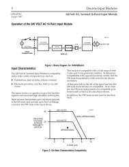
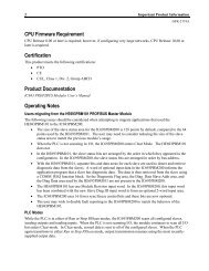
ÎÎÎÎIntroduction5.2. TimingThe <strong>Bus</strong> <strong>Interface</strong> <strong>Unit</strong> provides power to all I/O modules that are installed at the station. I/O module operationis governed by a System Reset signal to ensure controlled operation during the power up and shut down processes.As shown in the timing diagram below, momentary power losses of less than 10 milliseconds do not affect I/Omodule operation; however, longer power losses generate a Reset for all system I/O modules.24VDCNominalInputPower OnVoltageOvershoot5% (max)MomentaryPowerLossVoltageOvershoot5% (max)InputPower Off464566.5V Output200ms(min)95% (min) HoldUpTime10ms(min)200ms(min)HoldUpTime10ms(min)3ms(min)3ms(min)RST5.3. Calculating Input Power Requirements for a <strong>Bus</strong> <strong>Interface</strong> <strong>Unit</strong>The chart below shows typical input power requirements for the 24 VDC power supply.4642212(12.3)TypicalInputPower(Watts)8642ÎÎ(3.4)(5.5)(7.7)(10)0.25 0.5 0.7 1.0Total Backplane Current5(Amps)Page 1–8<strong>Alspa</strong> <strong>CE80–20</strong> <strong>FIP</strong> <strong>Bus</strong> <strong>Interface</strong> <strong>Unit</strong> User’s <strong>Manual</strong>ALS 52311 b–en