Alspa CE80–20 FIP Bus Interface Unit User's Manual
Alspa CE80–20 FIP Bus Interface Unit User's Manual
Alspa CE80–20 FIP Bus Interface Unit User's Manual

You also want an ePaper? Increase the reach of your titles
YUMPU automatically turns print PDFs into web optimized ePapers that Google loves.
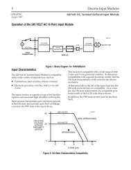
Introduction6. BUS INTERFACE UNIT TERMINAL BLOCKThe <strong>Bus</strong> <strong>Interface</strong> <strong>Unit</strong> provides terminals for power and ground connections. Maximum wire size is 2.10 mm 2AWG No.14.The <strong>Bus</strong> <strong>Interface</strong> <strong>Unit</strong> Terminal Block also has two connectors for attachment to a single or dual <strong>FIP</strong> bus.A connecting cable is provided with each I/O Terminal Block. It is used to connect the <strong>Bus</strong> <strong>Interface</strong> <strong>Unit</strong> TerminalBlock to the first I/O Terminal Block. The same type of cable interconnects subsequent I/O Terminal Blocks. Thecable has molded connectors that are keyed to assure proper orientation.The <strong>Bus</strong> <strong>Interface</strong> <strong>Unit</strong> Terminal Block stores the configuration parameters for the station. The <strong>Bus</strong> <strong>Interface</strong> <strong>Unit</strong>can be removed without removing the wiring or reconfiguring the station.46457<strong>FIP</strong> <strong>Bus</strong>ConnectorsTerminals forpower wiringI/O Terminal BlockConnectorsConnectingCableSpecifications for the <strong>Bus</strong> <strong>Interface</strong> <strong>Unit</strong> terminal block are listed on §7. Wiring information is in chapter 2, § 9.Page 1–10<strong>Alspa</strong> <strong>CE80–20</strong> <strong>FIP</strong> <strong>Bus</strong> <strong>Interface</strong> <strong>Unit</strong> User’s <strong>Manual</strong>ALS 52311 b–en