Alspa CE80–20 FIP Bus Interface Unit User's Manual
Alspa CE80–20 FIP Bus Interface Unit User's Manual
Alspa CE80–20 FIP Bus Interface Unit User's Manual

You also want an ePaper? Increase the reach of your titles
YUMPU automatically turns print PDFs into web optimized ePapers that Google loves.
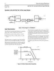
Installation12. CONNECTING THE COMMUNICATIONS BUSFor information about cable type, termination, grounding, and connections between devices, please refer to theALS 52310 <strong>FIP</strong> <strong>Bus</strong> Controller (FBC) for <strong>Alspa</strong> C80–75 PLC User’s <strong>Manual</strong>.Attach <strong>FIP</strong> bus cable(s) to the connectors on the front of the <strong>Bus</strong> <strong>Interface</strong> <strong>Unit</strong>. When installed in a single mediaor simplex configuration, either connector may be used.46508Connector for Channel 1Connector for Channel 2Note: If only one <strong>FIP</strong> bus is used, it is recommended that you cover the unused <strong>FIP</strong> bus connector with an anti-staticcap.Pin Assignments for the <strong>FIP</strong> <strong>Bus</strong> ConnectorsThe diagram below shows pin assignments for both <strong>FIP</strong> bus connectors on the front of the BIU.54 93 8D–2176D+46509Page 2–12<strong>Alspa</strong> <strong>CE80–20</strong> <strong>FIP</strong> <strong>Bus</strong> <strong>Interface</strong> <strong>Unit</strong> User’s <strong>Manual</strong>ALS 52311 b–en