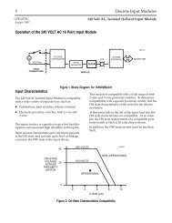
Alspa C80-35 24 Vdc Input, Neg/Pos Logic, 1 ms ... - GE Fanuc PLC
Alspa C80-35 24 Vdc Input, Neg/Pos Logic, 1 ms ... - GE Fanuc PLC
Alspa C80-35 24 Vdc Input, Neg/Pos Logic, 1 ms ... - GE Fanuc PLC

You also want an ePaper? Increase the reach of your titles
YUMPU automatically turns print PDFs into web optimized ePapers that Google loves.
<strong>Alspa</strong>IC693MDL655New In Stock!Cegelec Alstom <strong>Alspa</strong>http://www.pdfsupply.com/automation/cegelec-alstom-alspa/alspa-c80-61/<strong>Alspa</strong>IC693MDL655<strong>Alspa</strong> <strong>C80</strong>-611-919-5<strong>35</strong>-3180<strong>Alspa</strong> <strong>C80</strong>-<strong>35</strong> <strong>24</strong> <strong>Vdc</strong> <strong>Input</strong>, <strong>Neg</strong>/<strong>Pos</strong> <strong>Logic</strong>, 1 <strong>ms</strong>, (32 pts)www.pdfsupply.comEmail:sales@pdfsupply.com
RevisionsIndex letter Date Nature of revisionb September 1995 Changes made to this manual reflect the features of Release 5 (October1994) of <strong>Alspa</strong> P8–25/<strong>35</strong>/05 software for <strong>Alspa</strong> <strong>C80</strong>–<strong>35</strong> <strong>PLC</strong>s,<strong>Alspa</strong> <strong>C80</strong>–25 <strong>PLC</strong>s, and <strong>Alspa</strong> <strong>C80</strong>–05 Micro <strong>PLC</strong>s. Additionally,corrections have been made where necessary. The following list describesthe major revisions of this manual, as compared to the previousversion (ALS 52102 a):This manual includes software-related information about therecently released Model <strong>35</strong>1 CPU, such as sweep impact (referto chapter 2) and timing information (refer to appendix A). Foradditional information about the <strong>35</strong>1 CPU, refer to the ALS 52117<strong>Alspa</strong> <strong>C80</strong>–<strong>35</strong> <strong>PLC</strong> Installation Manual and the IPI that comeswith the CPU.There is a new <strong>Alspa</strong> 8000 Micro <strong>PLC</strong>, Model CE693UDR005,discussed briefly in chapter 2. This Micro <strong>PLC</strong> has 28 DC inputsand 28 relay outputs. For more information about ModelCE693UDD005, refer to the ALS 52119 <strong>Alspa</strong> <strong>C80</strong>–05 Micro<strong>PLC</strong> User’s Manual.In our effort to improve the quality of <strong>Alspa</strong> P8 documentation,there are clarifications and corrections in several places withinthis manual. In addition to minor clarifications, we reorganizedand improved the paragraph on Communication Requestsbeginning on page 4–72.c June 1997 Release 7 for software and CPUMath functions, chapter 4 (trigo, logarithmic, exponentical,radian), Real functions (floating point only CPU <strong>35</strong>2) chapter 4. Key switch function, chapter 2.ALS 52102 c–en <strong>Alspa</strong> <strong>C80</strong>–<strong>35</strong>, <strong>C80</strong>–25 and <strong>C80</strong>–05 <strong>PLC</strong>s Reference ManualPage 3
PrefaceThis manual describes the operation, fault handling and <strong>Alspa</strong> P8 programming instructions for the <strong>Alspa</strong> <strong>C80</strong>–<strong>35</strong>,<strong>Alspa</strong> <strong>C80</strong>–25 and <strong>Alspa</strong> <strong>C80</strong>–05 Micro programmable controllers. The <strong>Alspa</strong> <strong>C80</strong>–<strong>35</strong> <strong>PLC</strong>, <strong>Alspa</strong> <strong>C80</strong>–25 and<strong>Alspa</strong> <strong>C80</strong>–05 Micro <strong>PLC</strong> are members of the <strong>Alspa</strong> 8000 range of programmable logic controllers from Cegelec.1. CONTENT OF THIS MANUALThis manual contains the following chapters and appendices.Chapter 1. Introduction: provides an overview of the <strong>Alspa</strong> <strong>C80</strong>–<strong>35</strong> <strong>PLC</strong>, <strong>Alspa</strong> <strong>C80</strong>–25 <strong>PLC</strong> and <strong>Alspa</strong> <strong>C80</strong>–05Micro <strong>PLC</strong> and the <strong>Alspa</strong> P8–25/<strong>35</strong>/05 instruction set.Chapter 2. System Operation: describes certain System operations of the <strong>Alspa</strong> <strong>C80</strong>–<strong>35</strong> <strong>PLC</strong>, <strong>Alspa</strong> <strong>C80</strong>–25<strong>PLC</strong> or <strong>Alspa</strong> <strong>C80</strong>–05 Micro <strong>PLC</strong>. This includes a discussion of the <strong>PLC</strong> sweep sequences, the power–up andpower–down sequences, clocks and timers, security, I/O and fault handling. It also includes general informationfor a basic understanding of programming ladder logic.Chapter 3. Fault Explanations and Correction: provides troubleshooting information for an <strong>Alspa</strong> <strong>C80</strong>–<strong>35</strong>,<strong>C80</strong>–25 or <strong>C80</strong>–05 <strong>PLC</strong>. It explains fault descriptions in the <strong>PLC</strong> fault table and fault categories in the I/O faulttable.Chapter 4. <strong>Alspa</strong> P8–25/<strong>35</strong>/05 Instruction Set: describes programming instructions available for the <strong>Alspa</strong><strong>C80</strong>–<strong>35</strong> <strong>PLC</strong>, <strong>Alspa</strong> <strong>C80</strong>–25 <strong>PLC</strong> and <strong>Alspa</strong> <strong>C80</strong>–05 Micro <strong>PLC</strong>. The information in this chapter is arranged assections that correspond to the main program function groups.Appendix A. Instruction Timing: lists the memory size in bytes and execution time in microseconds for eachprogramming instruction. Memory size is the number of bytes required by the function in a ladder diagramapplication program.Appendix B. Interpreting Fault Tables: describes how to interpret the message structure format when readingthe fault tables using <strong>Alspa</strong> P8–25/<strong>35</strong>/05 software.Appendix C. Instruction Mnemonics: lists mnemonics that can be typed to display programming instructionswhile searching through or editing a program.Appendix D. Key Functions: lists the special keyboard assignments used for the <strong>Alspa</strong> P8–25/<strong>35</strong>/05 software.ALS 52102 c–en <strong>Alspa</strong> <strong>C80</strong>–<strong>35</strong>, <strong>C80</strong>–25 and <strong>C80</strong>–05 <strong>PLC</strong>s Reference ManualPage 5
Preface2. RELATED PUBLICATIONSALS 52105 <strong>Alspa</strong> <strong>C80</strong>–25 <strong>PLC</strong> User’s Manual.ALS 52109 MegaBasic Language for PCM Reference Manual and Programmer’s Guide.ALS 52117 <strong>Alspa</strong> <strong>C80</strong>–<strong>35</strong> <strong>PLC</strong> Installation Manual.ALS 52118 <strong>Alspa</strong> <strong>C80</strong>–<strong>35</strong> <strong>PLC</strong> I/O Module Specifications.ALS 52119 <strong>Alspa</strong> <strong>C80</strong>–05 Micro <strong>PLC</strong> User’s Manual.ALS 52201 <strong>Alspa</strong> P8–25/<strong>35</strong>/05 Programming Software for <strong>Alspa</strong> <strong>C80</strong>–<strong>35</strong>, <strong>C80</strong>–25 and <strong>C80</strong>–05 <strong>PLC</strong>s User’sManual.ALS 52202 Hand–Held Programmer for <strong>Alspa</strong> <strong>C80</strong>–<strong>35</strong>, <strong>C80</strong>–25 and <strong>C80</strong>–05 <strong>PLC</strong>s User’s Manual.ALS 52203 PCM Development Software (PCOP) for <strong>Alspa</strong> 8000 <strong>PLC</strong>s User’s Manual.ALS 52307 <strong>Alspa</strong> CE80–20 – N80 Bus Interface Unit User’s Manual.ALS 52310 FIP Bus Controller (FBC) for <strong>Alspa</strong> <strong>C80</strong>–75 <strong>PLC</strong> User’s Manual.ALS 52311 <strong>Alspa</strong> CE80–20 FIP Bus Interface Unit User’s Manual.ALS 52313 <strong>Alspa</strong> CE80–<strong>35</strong> Remote I/O Scanner User’s Manual.ALS 5<strong>24</strong>01 High Speed Counter for <strong>Alspa</strong> <strong>C80</strong>–<strong>35</strong> <strong>PLC</strong> User’s Manual.ALS 5<strong>24</strong>02 Programmable Coprocessor Module (PCM) and Support Software for <strong>Alspa</strong> 8000 <strong>PLC</strong>s User’s Manual.ALS 5<strong>24</strong>03 Axis <strong>Pos</strong>itioning Module (APM) for <strong>Alspa</strong> <strong>C80</strong>–<strong>35</strong> <strong>PLC</strong> Standard Mode User’s Manual.ALS 52501 N80 Communications Module (NCM) for <strong>Alspa</strong> <strong>C80</strong>–<strong>35</strong> <strong>PLC</strong> User’s Manual.ALS 52506 Serial communication modules for <strong>Alspa</strong> 8000 <strong>PLC</strong>s User’s Manual.ALS 52511 <strong>Alspa</strong> <strong>C80</strong>–<strong>35</strong> <strong>PLC</strong> Bus Controller for <strong>Alspa</strong> N80 Network (NBC) User’s Manual.ALS 52604 Alphanumeric Display System User’s Manual.ALS 52605 Alphanumeric Display System Reference Manual.ALS 52607 Axis <strong>Pos</strong>itioning Module (APM) for <strong>Alspa</strong> <strong>C80</strong>–<strong>35</strong> <strong>PLC</strong> – Follower Mode User’s Manual.GFK–0468–ALS <strong>Alspa</strong> P8–25/<strong>35</strong> Important Product Information.GFK–0521 Alphanumeric Display Coprocessor Module Data Sheet.Page 6<strong>Alspa</strong> <strong>C80</strong>–<strong>35</strong>, <strong>C80</strong>–25 and <strong>C80</strong>–05 <strong>PLC</strong>s Reference ManualALS 52102 c–en
Preface3. MANUAL NUMBERSIn some cases, <strong>Alspa</strong> 8000 manuals may be issued with numbers that differ from the one given under ”RelatedPublications” in the Preface of other manuals, or in Important Product Information or data sheets.The contents are similar.The table below shows the correspondence between ”ALS” and equivalent numbers for the manuals concerned:ALS NumberALS 52113ALS 52302ALS 52303ALS 5<strong>24</strong>04ALS 5<strong>24</strong>05ALS 52503Other NumberGFK–0600<strong>GE</strong>K–90486–2GFZ–0043GFK–0415GFK–0819GFK–0585ALS NumberALS 52507ALS 52508ALS 52514ALS 52515ALS 52523ALS 52603Other NumberGFK–0074GFK–0868GFK–0870GFK–1026GFK–1063GFK–0450ÁÁÁÁÁÁÁÁÁÁÁÁÁÁÁÁÁÁÁÁÁÁÁÁÁÁÁÁÁÁÁÁÁÁÁÁÁÁÁÁÁÁÁÁÁÁÁÁÁÁÁÁÁÁÁÁÁÁÁÁÁÁÁÁÁÁÁÁÁÁÁÁÁÁÁÁÁÁÁÁÁÁÁÁÁÁÁÁÁÁÁÁÁÁÁÁÁÁÁÁÁÁÁÁÁÁÁÁÁÁÁÁÁÁÁÁÁÁÁÁÁÁÁÁÁÁÁÁÁÁÁÁÁÁÁÁÁÁÁÁÁÁÁÁÁÁÁÁÁÁÁÁÁÁÁÁÁÁÁÁÁÁÁÁÁÁÁÁÁÁÁÁÁÁÁÁÁÁÁÁÁÁÁÁÁÁÁÁÁÁÁÁÁ4. WE WELCOME YOUR COMMENTS AND SUG<strong>GE</strong>STIONSÁÁÁÁÁÁÁÁÁÁÁÁÁÁÁÁÁÁÁÁÁÁÁÁÁÁÁÁÁÁÁÁCegelec strives to produce quality technical documentation. Please take the time to fill in and return the ”Reader’sComment” page if you have any remarks or suggestions.ALS 52102 c–en <strong>Alspa</strong> <strong>C80</strong>–<strong>35</strong>, <strong>C80</strong>–25 and <strong>C80</strong>–05 <strong>PLC</strong>s Reference ManualPage 7
PrefacePage 8<strong>Alspa</strong> <strong>C80</strong>–<strong>35</strong>, <strong>C80</strong>–25 and <strong>C80</strong>–05 <strong>PLC</strong>s Reference ManualALS 52102 c–en
Reader’s commentsALS 52102 c–en<strong>Alspa</strong> <strong>C80</strong>–<strong>35</strong>, <strong>C80</strong>–25 and <strong>C80</strong>–05 <strong>PLC</strong>s ReferenceManualYour main job is:System designerDistributorSystem integratorInstallerProgrammerMaintenanceOperatorOther (specify below)If you would like a personal reply, please fill in your name and address below:COMPANY:. . . . . . . . . . . . . . . . . . . . . . . . NAME: . . . . . . . . . . . . . . . . . . . . . . . . . . . . . . . . .ADDRESS: . . . . . . . . . . . . . . . . . . . . . . . . . . . . . . . . . . . . . . . . . . . . . . . . . . . . . . . . . . . . . . . . .. . . . . . . . . . . . . . . . . . . . . . . . . . . . . . . . . . . COUNTRY: . . . . . . . . . . . . . . . . . . . . . . . . . . . . . .Send this form directly to your CE<strong>GE</strong>LEC sales representative or to this address:CegelecService Documentation Produit (DPI)5 avenue Newton BP 21592142 Clamart CedexFranceFax: +33 (0)1 46 29 12 44All comments will be considered by qualified personnel.REMARKSContinue on back if necessaryALS 52102 c–en <strong>Alspa</strong> <strong>C80</strong>–<strong>35</strong>, <strong>C80</strong>–25 and <strong>C80</strong>–05 <strong>PLC</strong>s Reference ManualPage 9
Reader’s commentsPage 10<strong>Alspa</strong> <strong>C80</strong>–<strong>35</strong>, <strong>C80</strong>–25 and <strong>C80</strong>–05 <strong>PLC</strong>s Reference ManualALS 52102 c–en
Contents5.3.2. Valid Memory Types . . . . . . . . . . . . . . . . . . . . . . . . . . . . . . . . . . . . . . . . . . . . . . . . . . . . . . . 4–465.4. SHL and SHR (WORD) . . . . . . . . . . . . . . . . . . . . . . . . . . . . . . . . . . . . . . . . . . 4–475.4.1. Parameters . . . . . . . . . . . . . . . . . . . . . . . . . . . . . . . . . . . . . . . . . . . . . . . . . . . . . . . . . . . . . . . 4–485.4.2. Valid Memory Types . . . . . . . . . . . . . . . . . . . . . . . . . . . . . . . . . . . . . . . . . . . . . . . . . . . . . . . 4–485.5. ROL and ROR (WORD) . . . . . . . . . . . . . . . . . . . . . . . . . . . . . . . . . . . . . . . . . . 4–495.5.1. Parameters . . . . . . . . . . . . . . . . . . . . . . . . . . . . . . . . . . . . . . . . . . . . . . . . . . . . . . . . . . . . . . . 4–495.5.2. Valid Memory Types . . . . . . . . . . . . . . . . . . . . . . . . . . . . . . . . . . . . . . . . . . . . . . . . . . . . . . . 4–505.6. BTST (WORD) . . . . . . . . . . . . . . . . . . . . . . . . . . . . . . . . . . . . . . . . . . . . . . . . . . 4–515.6.1. Parameters . . . . . . . . . . . . . . . . . . . . . . . . . . . . . . . . . . . . . . . . . . . . . . . . . . . . . . . . . . . . . . . 4–515.6.2. Valid Memory Types . . . . . . . . . . . . . . . . . . . . . . . . . . . . . . . . . . . . . . . . . . . . . . . . . . . . . . . 4–515.7. BSET and BCLR (WORD) . . . . . . . . . . . . . . . . . . . . . . . . . . . . . . . . . . . . . . . . 4–525.7.1. Parameters . . . . . . . . . . . . . . . . . . . . . . . . . . . . . . . . . . . . . . . . . . . . . . . . . . . . . . . . . . . . . . . 4–5<strong>35</strong>.7.2. Valid Memory Types . . . . . . . . . . . . . . . . . . . . . . . . . . . . . . . . . . . . . . . . . . . . . . . . . . . . . . . 4–5<strong>35</strong>.8. BPOS (WORD) . . . . . . . . . . . . . . . . . . . . . . . . . . . . . . . . . . . . . . . . . . . . . . . . . . 4–545.8.1. Parameters . . . . . . . . . . . . . . . . . . . . . . . . . . . . . . . . . . . . . . . . . . . . . . . . . . . . . . . . . . . . . . . 4–545.8.2. Valid Memory Types . . . . . . . . . . . . . . . . . . . . . . . . . . . . . . . . . . . . . . . . . . . . . . . . . . . . . . . 4–545.9. MSKCMP (WORD, DWORD) . . . . . . . . . . . . . . . . . . . . . . . . . . . . . . . . . . . . 4–565.9.1. Parameters . . . . . . . . . . . . . . . . . . . . . . . . . . . . . . . . . . . . . . . . . . . . . . . . . . . . . . . . . . . . . . . 4–575.9.2. Valid Memory Types . . . . . . . . . . . . . . . . . . . . . . . . . . . . . . . . . . . . . . . . . . . . . . . . . . . . . . . 4–576. DATA MOVE FUNCTIONS . . . . . . . . . . . . . . . . . . . . . . . . . . . . . . . . . . . . . . . . . . . . . . . 4–606.1. MOVE (BIT, INT, WORD) . . . . . . . . . . . . . . . . . . . . . . . . . . . . . . . . . . . . . . . . . 4–606.1.1. Parameters . . . . . . . . . . . . . . . . . . . . . . . . . . . . . . . . . . . . . . . . . . . . . . . . . . . . . . . . . . . . . . . 4–616.1.2. Valid Memory Types . . . . . . . . . . . . . . . . . . . . . . . . . . . . . . . . . . . . . . . . . . . . . . . . . . . . . . . 4–626.2. BLKMOV (INT, WORD, REAL) . . . . . . . . . . . . . . . . . . . . . . . . . . . . . . . . . . . . 4–636.2.1. Parameters . . . . . . . . . . . . . . . . . . . . . . . . . . . . . . . . . . . . . . . . . . . . . . . . . . . . . . . . . . . . . . . 4–636.2.2. Valid Memory Types . . . . . . . . . . . . . . . . . . . . . . . . . . . . . . . . . . . . . . . . . . . . . . . . . . . . . . . 4–646.3. BLKCLR (WORD) . . . . . . . . . . . . . . . . . . . . . . . . . . . . . . . . . . . . . . . . . . . . . . . 4–656.3.1. Parameters . . . . . . . . . . . . . . . . . . . . . . . . . . . . . . . . . . . . . . . . . . . . . . . . . . . . . . . . . . . . . . . 4–656.3.2. Valid Memory Types . . . . . . . . . . . . . . . . . . . . . . . . . . . . . . . . . . . . . . . . . . . . . . . . . . . . . . . 4–656.4. SHFR (BIT, WORD) . . . . . . . . . . . . . . . . . . . . . . . . . . . . . . . . . . . . . . . . . . . . . . 4–666.4.1. Parameters . . . . . . . . . . . . . . . . . . . . . . . . . . . . . . . . . . . . . . . . . . . . . . . . . . . . . . . . . . . . . . . 4–676.4.2. Valid Memory Types . . . . . . . . . . . . . . . . . . . . . . . . . . . . . . . . . . . . . . . . . . . . . . . . . . . . . . . 4–676.5. BITSEQ (BIT) . . . . . . . . . . . . . . . . . . . . . . . . . . . . . . . . . . . . . . . . . . . . . . . . . . . 4–696.5.1. Memory Required for a Bit Sequencer . . . . . . . . . . . . . . . . . . . . . . . . . . . . . . . . . . . . . . . . . 4–69CHAPTER 5 – ALSPA P8–25/<strong>35</strong>/05 INSTRUCTION SET . . . . . . . . . . . . . . . . . . . . . . . . . . 4–706.5.2. Parameters . . . . . . . . . . . . . . . . . . . . . . . . . . . . . . . . . . . . . . . . . . . . . . . . . . . . . . . . . . . . . . . 4–706.5.3. Valid Memory Types . . . . . . . . . . . . . . . . . . . . . . . . . . . . . . . . . . . . . . . . . . . . . . . . . . . . . . . 4–716.6. COMMREQ . . . . . . . . . . . . . . . . . . . . . . . . . . . . . . . . . . . . . . . . . . . . . . . . . . . . . . 4–726.6.1. Command Block . . . . . . . . . . . . . . . . . . . . . . . . . . . . . . . . . . . . . . . . . . . . . . . . . . . . . . . . . . 4–726.6.2. Parameters . . . . . . . . . . . . . . . . . . . . . . . . . . . . . . . . . . . . . . . . . . . . . . . . . . . . . . . . . . . . . . . 4–736.6.3. Valid Memory Types . . . . . . . . . . . . . . . . . . . . . . . . . . . . . . . . . . . . . . . . . . . . . . . . . . . . . . . 4–747. TABLE FUNCTIONS . . . . . . . . . . . . . . . . . . . . . . . . . . . . . . . . . . . . . . . . . . . . . . . . . . . . 4–757.1. ARRAY_MOVE (INT, DINT, BIT, BYTE, WORD) . . . . . . . . . . . . . . . . . . . . . 4–767.1.1. Parameters . . . . . . . . . . . . . . . . . . . . . . . . . . . . . . . . . . . . . . . . . . . . . . . . . . . . . . . . . . . . . . . 4–777.1.2. Valid Memory Types . . . . . . . . . . . . . . . . . . . . . . . . . . . . . . . . . . . . . . . . . . . . . . . . . . . . . . . 4–777.2. SRCH_EQ and SRCH_NE (INT, DINT, BYTE, WORD)SRCH_GT and SRCH_LTSRCH_<strong>GE</strong> and SRCH_LE . . . . . . . . . . . . . . . . . . . . . . . . . . . . . . . . . . . . . . . . . . . 4–797.2.1. Parameters . . . . . . . . . . . . . . . . . . . . . . . . . . . . . . . . . . . . . . . . . . . . . . . . . . . . . . . . . . . . . . . 4–807.2.2. Valid Memory Types . . . . . . . . . . . . . . . . . . . . . . . . . . . . . . . . . . . . . . . . . . . . . . . . . . . . . . . 4–80ALS 52102 c–en <strong>Alspa</strong> <strong>C80</strong>–<strong>35</strong>, <strong>C80</strong>–25 and <strong>C80</strong>–05 <strong>PLC</strong>s Reference Manual Page 15
Contents9.10. PID . . . . . . . . . . . . . . . . . . . . . . . . . . . . . . . . . . . . . . . . . . . . . . . . . . . . . . . . . . . . 4–1239.10.1. Parameters . . . . . . . . . . . . . . . . . . . . . . . . . . . . . . . . . . . . . . . . . . . . . . . . . . . . . . . . . . . . . . . 4–1<strong>24</strong>9.10.2. Valid Memory Types . . . . . . . . . . . . . . . . . . . . . . . . . . . . . . . . . . . . . . . . . . . . . . . . . . . . . . . 4–1<strong>24</strong>9.10.3. PID Parameter Bloc . . . . . . . . . . . . . . . . . . . . . . . . . . . . . . . . . . . . . . . . . . . . . . . . . . . . . . . 4–1259.10.4. Operation of the PID Instruction . . . . . . . . . . . . . . . . . . . . . . . . . . . . . . . . . . . . . . . . . . . . . . 4–1269.10.5. Internal Parameters in RefArray . . . . . . . . . . . . . . . . . . . . . . . . . . . . . . . . . . . . . . . . . . . . . . 4–1319.10.6. PID Algorithm Selection (PIDISA or PIDIND) and Gains . . . . . . . . . . . . . . . . . . . . . . . . . . 4–1319.10.7. CV Amplitude and Rate Limits . . . . . . . . . . . . . . . . . . . . . . . . . . . . . . . . . . . . . . . . . . . . . . . 4–1329.10.8. Sample Period and PID Block Scheduling . . . . . . . . . . . . . . . . . . . . . . . . . . . . . . . . . . . . . . 4–1339.10.9. Determining the Process Characteristics . . . . . . . . . . . . . . . . . . . . . . . . . . . . . . . . . . . . . . . . 4–1339.10.10. Setting User Parameters Including Tuning Loop Gains . . . . . . . . . . . . . . . . . . . . . . . . . . . . . 4–1349.10.11. Setting Loop Gains — Ziegler and Nichols Tuning Approach . . . . . . . . . . . . . . . . . . . . . . . 4–1<strong>35</strong>9.10.12. Sample PID Call . . . . . . . . . . . . . . . . . . . . . . . . . . . . . . . . . . . . . . . . . . . . . . . . . . . . . . . . . . 4–136APPENDIX A – INSTRUCTION TIMING . . . . . . . . . . . . . . . . . . . . . . . . . . . . . . . . . . . . . . . A–1APPENDIX B – INTERPRETING FAULTS USING ALSPA P8–25/<strong>35</strong>/05 SOFTWARE . . B–11. <strong>PLC</strong> FAULT TABLE . . . . . . . . . . . . . . . . . . . . . . . . . . . . . . . . . . . . . . . . . . . . . . . . . . . . . B–31.1. Long/Short Indicator . . . . . . . . . . . . . . . . . . . . . . . . . . . . . . . . . . . . . . . . . . . . . . . . B–41.2. Spare . . . . . . . . . . . . . . . . . . . . . . . . . . . . . . . . . . . . . . . . . . . . . . . . . . . . . . . . . . . . B–41.3. Rack . . . . . . . . . . . . . . . . . . . . . . . . . . . . . . . . . . . . . . . . . . . . . . . . . . . . . . . . . . . . . B–41.4. Slot . . . . . . . . . . . . . . . . . . . . . . . . . . . . . . . . . . . . . . . . . . . . . . . . . . . . . . . . . . . . . B–41.5. Task . . . . . . . . . . . . . . . . . . . . . . . . . . . . . . . . . . . . . . . . . . . . . . . . . . . . . . . . . . . . . B–41.6. <strong>PLC</strong> Fault Group . . . . . . . . . . . . . . . . . . . . . . . . . . . . . . . . . . . . . . . . . . . . . . . . . . . B–51.7. Fault Action . . . . . . . . . . . . . . . . . . . . . . . . . . . . . . . . . . . . . . . . . . . . . . . . . . . . . . . B–51.8. Error Code . . . . . . . . . . . . . . . . . . . . . . . . . . . . . . . . . . . . . . . . . . . . . . . . . . . . . . . . B–61.9. Fault Extra Data . . . . . . . . . . . . . . . . . . . . . . . . . . . . . . . . . . . . . . . . . . . . . . . . . . . . B–81.9.1. Corrupted User RAM Group . . . . . . . . . . . . . . . . . . . . . . . . . . . . . . . . . . . . . . . . . . . . . . . . . B–81.9.2. <strong>PLC</strong> CPU Hardware Failure (RAM Failure) . . . . . . . . . . . . . . . . . . . . . . . . . . . . . . . . . . . . . B–81.10. <strong>PLC</strong> Fault Time Stamp . . . . . . . . . . . . . . . . . . . . . . . . . . . . . . . . . . . . . . . . . . . . . . B–82. I/O FAULT TABLE . . . . . . . . . . . . . . . . . . . . . . . . . . . . . . . . . . . . . . . . . . . . . . . . . . . . . . B–92.1. Long/Short Indicator . . . . . . . . . . . . . . . . . . . . . . . . . . . . . . . . . . . . . . . . . . . . . . . . B–102.2. Reference Address . . . . . . . . . . . . . . . . . . . . . . . . . . . . . . . . . . . . . . . . . . . . . . . . . . B–102.3. I/O Fault Address . . . . . . . . . . . . . . . . . . . . . . . . . . . . . . . . . . . . . . . . . . . . . . . . . . B–102.4. Rack . . . . . . . . . . . . . . . . . . . . . . . . . . . . . . . . . . . . . . . . . . . . . . . . . . . . . . . . . . . . . B–112.5. Slot . . . . . . . . . . . . . . . . . . . . . . . . . . . . . . . . . . . . . . . . . . . . . . . . . . . . . . . . . . . . . B–112.6. Point . . . . . . . . . . . . . . . . . . . . . . . . . . . . . . . . . . . . . . . . . . . . . . . . . . . . . . . . . . . . B–112.7. I/O Fault Group . . . . . . . . . . . . . . . . . . . . . . . . . . . . . . . . . . . . . . . . . . . . . . . . . . . . B–112.8. I/O Fault Action . . . . . . . . . . . . . . . . . . . . . . . . . . . . . . . . . . . . . . . . . . . . . . . . . . . B–122.9. I/O Fault Specific Data . . . . . . . . . . . . . . . . . . . . . . . . . . . . . . . . . . . . . . . . . . . . . . B–122.10. Symbolic Fault Specific Data . . . . . . . . . . . . . . . . . . . . . . . . . . . . . . . . . . . . . . . . . B–122.11. Fault Actions for Specific Faults . . . . . . . . . . . . . . . . . . . . . . . . . . . . . . . . . . . . . . . B–122.12. I/O Fault Time Stamp . . . . . . . . . . . . . . . . . . . . . . . . . . . . . . . . . . . . . . . . . . . . . . . B–12ALS 52102 c–en <strong>Alspa</strong> <strong>C80</strong>–<strong>35</strong>, <strong>C80</strong>–25 and <strong>C80</strong>–05 <strong>PLC</strong>s Reference Manual Page 17
ContentsAPPENDIX C – INSTRUCTION MNEMONICS . . . . . . . . . . . . . . . . . . . . . . . . . . . . . . . . . . C–1APPENDIX D – KEY FUNCTIONS . . . . . . . . . . . . . . . . . . . . . . . . . . . . . . . . . . . . . . . . . . . . . D–1APPENDIX E – USING FLOATING–POINT NUMBERS . . . . . . . . . . . . . . . . . . . . . . . . . . E–11. FLOATING-POINT NUMBERS . . . . . . . . . . . . . . . . . . . . . . . . . . . . . . . . . . . . . . . . . . . E–12. VALUES OF FLOATING-POINT NUMBERS . . . . . . . . . . . . . . . . . . . . . . . . . . . . . . . . E–23. ERRORS IN FLOATING-POINT NUMBERS AND OPERATIONS . . . . . . . . . . . . . . . E–44. ENTERING AND DISPLAYING FLOATING-POINT NUMBERS . . . . . . . . . . . . . . . E–5Page 18<strong>Alspa</strong> <strong>C80</strong>–<strong>35</strong>, <strong>C80</strong>–25 and <strong>C80</strong>–05 <strong>PLC</strong>s Reference ManualALS 52102 c–en
FiguresFigure 2.1 – <strong>PLC</strong> Sweep . . . . . . . . . . . . . . . . . . . . . . . . . . . . . . . . . . . . . . . . . . . . . . . . . . . . . . . . . . . . . . . 2–3Figure 2.2 – Programmer Communications Window Flow Chart . . . . . . . . . . . . . . . . . . . . . . . . . . . . . . . 2–9Figure 2.3 – System Communications Flow Chart . . . . . . . . . . . . . . . . . . . . . . . . . . . . . . . . . . . . . . . . . . . 2–10Figure 2.4 – PCM Communications with the <strong>PLC</strong> . . . . . . . . . . . . . . . . . . . . . . . . . . . . . . . . . . . . . . . . . . . 2–11Figure 2.5 – Power–Up Sequence . . . . . . . . . . . . . . . . . . . . . . . . . . . . . . . . . . . . . . . . . . . . . . . . . . . . . . . . 2–28Figure 2.6 – Time–Tick Contact Timing Diagram . . . . . . . . . . . . . . . . . . . . . . . . . . . . . . . . . . . . . . . . . . . 2–30Figure 2.7 – <strong>Alspa</strong> <strong>C80</strong>–<strong>35</strong> I/O Structure . . . . . . . . . . . . . . . . . . . . . . . . . . . . . . . . . . . . . . . . . . . . . . . . . . 2–34Figure 4.1 – Independent Term Algorithm (PIDIND) . . . . . . . . . . . . . . . . . . . . . . . . . . . . . . . . . . . . . . . . 4–132ALS 52102 c–en <strong>Alspa</strong> <strong>C80</strong>–<strong>35</strong>, <strong>C80</strong>–25 and <strong>C80</strong>–05 <strong>PLC</strong>s Reference Manual Page 19
TablesTable 2.1 – Sweep Time Contribution . . . . . . . . . . . . . . . . . . . . . . . . . . . . . . . . . . . . . . . . . . . . . . . . . . . . 2–4Table 2.2 – I/O Scan Time Contribution for <strong>Alspa</strong> <strong>C80</strong>–<strong>35</strong> Modules (in milliseconds) . . . . . . . . . . . . . 2–5Table 2.3 – I/O Scan Time Contribution for <strong>Alspa</strong> <strong>C80</strong>–<strong>35</strong> <strong>35</strong>1/<strong>35</strong>2 Module (in milliseconds) . . . . . . . 2–6Table 2.4 – Example Sweep Time Calculation (for an <strong>Alspa</strong> <strong>C80</strong>–<strong>35</strong> Model 331 <strong>PLC</strong>) . . . . . . . . . . . . . 2–7Table 2.5 – Register References . . . . . . . . . . . . . . . . . . . . . . . . . . . . . . . . . . . . . . . . . . . . . . . . . . . . . . . . 2–18Table 2.6 – Discrete References . . . . . . . . . . . . . . . . . . . . . . . . . . . . . . . . . . . . . . . . . . . . . . . . . . . . . . . . 2–19Table 2.7 – Data Types . . . . . . . . . . . . . . . . . . . . . . . . . . . . . . . . . . . . . . . . . . . . . . . . . . . . . . . . . . . . . . . 2–21Table 2.8 – System Status References . . . . . . . . . . . . . . . . . . . . . . . . . . . . . . . . . . . . . . . . . . . . . . . . . . . . 2–22Table 2.8 – System Status References – Continued . . . . . . . . . . . . . . . . . . . . . . . . . . . . . . . . . . . . . . . . . 2–23Table 2.9 – Model <strong>35</strong> I/O Modules . . . . . . . . . . . . . . . . . . . . . . . . . . . . . . . . . . . . . . . . . . . . . . . . . . . . . . 2–<strong>35</strong>Table 2.10 – Model 25 I/O Modules . . . . . . . . . . . . . . . . . . . . . . . . . . . . . . . . . . . . . . . . . . . . . . . . . . . . . 2–37Table 2.11 – Micro <strong>PLC</strong> Models . . . . . . . . . . . . . . . . . . . . . . . . . . . . . . . . . . . . . . . . . . . . . . . . . . . . . . . . 2–38Table 3.1 – Fault Summary . . . . . . . . . . . . . . . . . . . . . . . . . . . . . . . . . . . . . . . . . . . . . . . . . . . . . . . . . . . . 3–3Table 3.2 – Fault Actions . . . . . . . . . . . . . . . . . . . . . . . . . . . . . . . . . . . . . . . . . . . . . . . . . . . . . . . . . . . . . . 3–4Table 4.1 – Types of Contacts . . . . . . . . . . . . . . . . . . . . . . . . . . . . . . . . . . . . . . . . . . . . . . . . . . . . . . . . . . 4–2Table 4.2 – Types of Coils . . . . . . . . . . . . . . . . . . . . . . . . . . . . . . . . . . . . . . . . . . . . . . . . . . . . . . . . . . . . . 4–3Table 4.3 – Service Request Functions . . . . . . . . . . . . . . . . . . . . . . . . . . . . . . . . . . . . . . . . . . . . . . . . . . . 4–104Table 4.4 – PID Parameters Overview . . . . . . . . . . . . . . . . . . . . . . . . . . . . . . . . . . . . . . . . . . . . . . . . . . . 4–125Table 4.5 – PID Parameters Details . . . . . . . . . . . . . . . . . . . . . . . . . . . . . . . . . . . . . . . . . . . . . . . . . . . . . . 4–127Table 4.5 – PID Parameters Details (Continued) . . . . . . . . . . . . . . . . . . . . . . . . . . . . . . . . . . . . . . . . . . . 4–128Table 4.5 – PID Parameters Details (Continued) . . . . . . . . . . . . . . . . . . . . . . . . . . . . . . . . . . . . . . . . . . . 4–129Table 4.5 – PID Parameters Details (Continued) . . . . . . . . . . . . . . . . . . . . . . . . . . . . . . . . . . . . . . . . . . . 4–130Table A.1 – Instruction Timing . . . . . . . . . . . . . . . . . . . . . . . . . . . . . . . . . . . . . . . . . . . . . . . . . . . . . . . . . A–2Table A.1 – Instruction Timing – Continued . . . . . . . . . . . . . . . . . . . . . . . . . . . . . . . . . . . . . . . . . . . . . . A–3Table A.1 – Instruction Timing – Continued . . . . . . . . . . . . . . . . . . . . . . . . . . . . . . . . . . . . . . . . . . . . . . A–4Table A.1 – Instruction Timing – Continued . . . . . . . . . . . . . . . . . . . . . . . . . . . . . . . . . . . . . . . . . . . . . A–5Table A.1 – Instruction Timing – Continued . . . . . . . . . . . . . . . . . . . . . . . . . . . . . . . . . . . . . . . . . . . . . . A–6Table A.1 – Instruction Timing – Continued . . . . . . . . . . . . . . . . . . . . . . . . . . . . . . . . . . . . . . . . . . . . . . A–7Table A.1 – Instruction Timing – Continued . . . . . . . . . . . . . . . . . . . . . . . . . . . . . . . . . . . . . . . . . . . . . . A–8Table A.2 – Instruction Sizes for <strong>35</strong>1 and <strong>35</strong>2 CPUs . . . . . . . . . . . . . . . . . . . . . . . . . . . . . . . . . . . . . . . . A–8Table B.1 – <strong>PLC</strong> Fault Groups . . . . . . . . . . . . . . . . . . . . . . . . . . . . . . . . . . . . . . . . . . . . . . . . . . . . . . . . . B–5Table B.2 – <strong>PLC</strong> Fault Actions . . . . . . . . . . . . . . . . . . . . . . . . . . . . . . . . . . . . . . . . . . . . . . . . . . . . . . . . . B–5Table B.3 – Alarm Error Codes for <strong>PLC</strong> CPU Software Faults . . . . . . . . . . . . . . . . . . . . . . . . . . . . . . . . B–6Table B.4 – Alarm Error Codes for <strong>PLC</strong> Faults . . . . . . . . . . . . . . . . . . . . . . . . . . . . . . . . . . . . . . . . . . . . B–7Table B.5 – <strong>PLC</strong> Fault Data – Illegal Boolean Opcode Detected . . . . . . . . . . . . . . . . . . . . . . . . . . . . . . B–8Table B.6 – <strong>PLC</strong> Fault Time Stamp . . . . . . . . . . . . . . . . . . . . . . . . . . . . . . . . . . . . . . . . . . . . . . . . . . . . . B–8Table B.7 – I/O Fault Table Format Indicator Byte . . . . . . . . . . . . . . . . . . . . . . . . . . . . . . . . . . . . . . . . . B–10Table B.8 – I/O Reference Address . . . . . . . . . . . . . . . . . . . . . . . . . . . . . . . . . . . . . . . . . . . . . . . . . . . . . . B–10Table B.9 – I/O Reference Address Memory Type . . . . . . . . . . . . . . . . . . . . . . . . . . . . . . . . . . . . . . . . . . B–10Table B.10 – I/O Fault Groups . . . . . . . . . . . . . . . . . . . . . . . . . . . . . . . . . . . . . . . . . . . . . . . . . . . . . . . . . B–11Table B.11 – I/O Fault Actions . . . . . . . . . . . . . . . . . . . . . . . . . . . . . . . . . . . . . . . . . . . . . . . . . . . . . . . . . B–12Table B.12 – I/O Fault Specific Data . . . . . . . . . . . . . . . . . . . . . . . . . . . . . . . . . . . . . . . . . . . . . . . . . . . . B–12Table B.13 – I/O Fault Time Stamp . . . . . . . . . . . . . . . . . . . . . . . . . . . . . . . . . . . . . . . . . . . . . . . . . . . . . B–12Page 20<strong>Alspa</strong> <strong>C80</strong>–<strong>35</strong>, <strong>C80</strong>–25 and <strong>C80</strong>–05 <strong>PLC</strong>s Reference ManualALS 52102 c–en
Chapter1IntroductionThe <strong>Alspa</strong> <strong>C80</strong>–<strong>35</strong> <strong>PLC</strong>, <strong>Alspa</strong> <strong>C80</strong>–25 <strong>PLC</strong> and <strong>Alspa</strong> <strong>C80</strong>–05 Micro <strong>PLC</strong> are members of the Cegelec<strong>Alspa</strong> 8000 <strong>PLC</strong> range of programmable logic controllers (<strong>PLC</strong>s). They are easy to install and configure, offeradvanced programming features, and are compatible with the <strong>Alspa</strong> <strong>C80</strong>–75 <strong>PLC</strong>.The <strong>Alspa</strong> <strong>C80</strong>–25 <strong>PLC</strong> provides a cost–effective platform for low I/O count applications. The primary objectivesof the <strong>Alspa</strong> <strong>C80</strong>–25 <strong>PLC</strong> are:To provide a small <strong>PLC</strong> that is easy to use, install, upgrade and maintain.To provide a cost–effective family–compatible <strong>PLC</strong>.To provide easier system integration through standard communication hardware and protocols.The <strong>Alspa</strong> <strong>C80</strong>–05 Micro <strong>PLC</strong> also provides a cost-effective platform for lower I/O count applications. Theprimary objectives of the Micro <strong>PLC</strong> are the same as those for the <strong>Alspa</strong> <strong>C80</strong>–25. In addition, the Micro <strong>PLC</strong> offersthe following:The Micro <strong>PLC</strong> has the CPU, power supply, inputs and outputs all built into one small device.Most models also have a high speed counter.Because the CPU, power supply, inputs and outputs are all built into one device, it is very easy to configure.1. SOFTWARE ARCHITECTUREThe software structure for the <strong>Alspa</strong> <strong>C80</strong>–<strong>35</strong> <strong>PLC</strong> (except <strong>35</strong>1 models) and <strong>Alspa</strong> <strong>C80</strong>–25 <strong>PLC</strong> uses an architecturethat manages memory and execution priority in the 80188 microprocessor. Models <strong>35</strong>1 and <strong>35</strong>2 uses an 80386 EXmicroprocessor. The <strong>Alspa</strong> <strong>C80</strong>–05 Micro <strong>PLC</strong> uses the H8 microprocessor. This operation supports both programexecution and basic housekeeping tasks such as diagnostic routines, input/output scanners and alarm processing.The system software also contains routines to communicate with the programmer. These routines provide for theupload and download of application progra<strong>ms</strong>, return of status information, and control of the <strong>PLC</strong>.In the <strong>Alspa</strong> <strong>C80</strong>–<strong>35</strong> <strong>PLC</strong>, the application (user logic) program which controls the end process to which the <strong>PLC</strong>is applied is controlled by a dedicated Instruction Sequencer Coprocessor (ISCP). The ISCP is implemented inhardware in the Model 313 and higher and in software in the Model 311 syste<strong>ms</strong>, and the Micro <strong>PLC</strong>. The 80188microprocessor and the ISCP can execute simultaneously, allowing the microprocessor to service communicationswhile the ISCP is executing the bulk of the application program; however, the microprocessor must execute thenon–boolean function blocks.ALS 52102 c–en <strong>Alspa</strong> <strong>C80</strong>–<strong>35</strong>, <strong>C80</strong>–25 and <strong>C80</strong>–05 <strong>PLC</strong>s Reference Manual Page 1–1
Introduction2. FAULT HANDLINGFaults occur in the <strong>Alspa</strong> <strong>C80</strong>–<strong>35</strong> <strong>PLC</strong>, <strong>Alspa</strong> <strong>C80</strong>–25 and <strong>Alspa</strong> <strong>C80</strong>–05 Micro <strong>PLC</strong> when certain failures orconditions happen that affect the operation and performance of the system. These conditions may affect the abilityof the <strong>PLC</strong> to control a machine or process. Other conditions may only act as an alert, such as a low battery signalto indicate that the voltage of the battery protecting the memory is low and should be replaced. The condition orfailure is called a fault.Faults are handled by a software alarm processor function which records the faults in either the <strong>PLC</strong> fault tableor the I/O fault table. (The Model 331 and Model 340/341 CPUs also time–stamp the faults.) These tables can bedisplayed on the <strong>PLC</strong> Fault Table and I/O Fault Table screens in <strong>Alspa</strong> P8–25/<strong>35</strong>/05 software using the control andstatus functions.3. ALSPA <strong>C80</strong>–25, <strong>C80</strong>–<strong>35</strong>, <strong>C80</strong>–05 INSTRUCTION SETProgramming consists of creating an application program for a <strong>PLC</strong>. Because <strong>Alspa</strong> <strong>C80</strong>–<strong>35</strong>, <strong>C80</strong>–25 and <strong>C80</strong>–05Micro <strong>PLC</strong>s have a common instruction set, they can all be programmed using the same software. Chapter 4 ofthis manual describes the instruction set used to create ladder logic progra<strong>ms</strong> for the <strong>Alspa</strong> <strong>C80</strong>–<strong>35</strong>, <strong>C80</strong>–25 and<strong>C80</strong>–05 Micro <strong>PLC</strong>s.If the <strong>Alspa</strong> P8–25/<strong>35</strong>/05 programming software is not yet installed, please refer to the ALS 52201 <strong>Alspa</strong>P8–25/<strong>35</strong>/05 Programming Software for <strong>Alspa</strong> <strong>C80</strong>–<strong>35</strong>, <strong>C80</strong>–25 and <strong>C80</strong>–05 <strong>PLC</strong>s User’s Manual, forinstructions. The user’s manual explains how to create, transfer, edit and print progra<strong>ms</strong>.Configuration is the process of assigning logical addresses, as well as other characteristics, to the hardwaremodules in the system. It may be done either before or after programming, using the configuration software whichis part of <strong>Alspa</strong> P8–25/<strong>35</strong>/05 software; however, it is recommended that configuration be done first. If that has notbeen done, you should refer to the ALS 52201 <strong>Alspa</strong> P8–25/<strong>35</strong>/05 Programming Software for <strong>Alspa</strong> <strong>C80</strong>–<strong>35</strong>,<strong>C80</strong>–25 and <strong>C80</strong>–05 <strong>PLC</strong>s User’s Manual, to decide whether it is best to begin programming at this time.3.1. Contacts, Coils and LinksThe most basic elements of a program are relay functions, which are described in chapter 4, § 1. Relay Functions.These contacts and coils represent machine inputs and outputs, and can be used to control the flow of logic throughthe program. They enable or prevent the execution of other program functions in a rung and indicate the states ofoutputs. The <strong>Alspa</strong> P8 software provides many types of contacts and coils for maximum programming flexibility.3.2. Timers and CountersFor information about using an on–delay or stopwatch–type timer, as well as up and down counters, refer tochapter 4, § 2. Timers and Counters.Page 1–2<strong>Alspa</strong> <strong>C80</strong>–<strong>35</strong>, <strong>C80</strong>–25 and <strong>C80</strong>–05 <strong>PLC</strong>s Reference ManualALS 52102 c–en
Introduction3.3. MathMath functions include addition, subtraction, multiplication, division, modulo division and square root. Release7 also provides support for floating point math with the CPU <strong>35</strong>2 only. Floating point math uses the REAL datatype. Additional math instructions supported by the CPU <strong>35</strong>2 include trigonometric, logarithmic/exponential andradian conversion. These functions are explained in chapter 4, § 3. Math Functions.Each math function operates on two signed or double precision signed integer numbers of the same type. If thenumbers you are working with are not the same type (for example, if one is a signed integer and the other is in4–digit BCD format), you must first program one of the conversion functions (described in § 8.) to make the inputtypes match.3.4. Convert Data to Another TypeMany program functions (like the math functions) operate on numbers which must be of the same type. Use theconversion functions, described in chapter 4, § 8. Conversion Functions if you need to change a number to word,BCD, or signed integer format.3.5. Compare Two NumbersTo compare two numbers (which must be the same type), to see whether one is greater than, equal to, or less thanthe other, use one of the relational functions described in chapter 4, § 4. Relational Functions.3.6. Manipulate Bit StringsChapter 4, § 5. Bit Operation Functions, contains information about data move and boolean operations on datathat is in the form of bit strings:1. To perform boolean operations (AND, OR, XOR, NOT) on two bit strings of the same length.2. To create an output string that is a copy of an input bit string, but with its bits inverted, shifted, or rotated. Also,use the data move functions to clear an area of memory and fill it with typed data.3.7. Move DataRefer to chapter 4, § 6. Data Move Functions, to create program logic that will:1. Copy data to another location. Data is copied as individual bits.2. Move a block of constants into memory.3. Clear an area of discrete or register reference memory.4. Shift data from one memory location to another, capturing the data that has been shifted out.5. Perform a bit sequence shift through an array of bits.3.8. Array Move and SearchTo search for array values and compare them to a specified value or copy a specified number of data elements,use the table functions described in chapter 4, § 7. Table Functions.ALS 52102 c–en <strong>Alspa</strong> <strong>C80</strong>–<strong>35</strong>, <strong>C80</strong>–25 and <strong>C80</strong>–05 <strong>PLC</strong>s Reference ManualPage 1–3
Introduction3.9. Do I/OTo perform an immediate I/O update of rack–mounted modules in the system, use the DO I/O function describedin chapter 4, § 9. Control Functions.3.10. Communicate with Other ModulesIf the CPU must communicate with an intelligent module in the system (for example, to send data to a PCM), usea COMMREQ function. See chapter 4, § 9. Control Functions.3.11. Special Services from the <strong>PLC</strong>Use the SVCREQ function described in chapter 4, § 9. Control Functions to:1. Change/read the checksum task state and number of words to checksum.2. Change/read the time–of–day clock state and values.3. Shut down the <strong>PLC</strong>.4. Clear the fault tables.5. Read the last–logged fault table entry.6. Read the elapsed time clock.7. Read the I/O override status.8. Read Master Checksum.9. Interrogate I/O.10. Read Elapsed Power Down Time.3.12. Rung ExplanationTo add rung comment text to the program, use the COMMENT function described in chapter 4, § 9. ControlFunctions.3.13. Control FunctionsUse the MCR function to execute part of the program with negative logic, or the JUMP function to skip part ofthe program entirely. See chapter 4, § 9. Control Functions for information.Page 1–4<strong>Alspa</strong> <strong>C80</strong>–<strong>35</strong>, <strong>C80</strong>–25 and <strong>C80</strong>–05 <strong>PLC</strong>s Reference ManualALS 52102 c–en
Introduction3.14. Additional Reference InformationAppendix A lists the memory size in bytes and the execution time in microseconds for each programminginstruction described in chapter 4.Appendix B describes how to interpret the message structure format when reading the <strong>PLC</strong> and I/O fault tables.Refer to appendix C for a listing of the instruction mnemonics used with <strong>Alspa</strong> P8–25/<strong>35</strong>/05 software.Refer to appendix D for a listing of the special keyboard assignments used with <strong>Alspa</strong> P8–25/<strong>35</strong>/05 software.ALS 52102 c–en <strong>Alspa</strong> <strong>C80</strong>–<strong>35</strong>, <strong>C80</strong>–25 and <strong>C80</strong>–05 <strong>PLC</strong>s Reference ManualPage 1–5
IntroductionPage 1–6<strong>Alspa</strong> <strong>C80</strong>–<strong>35</strong>, <strong>C80</strong>–25 and <strong>C80</strong>–05 <strong>PLC</strong>s Reference ManualALS 52102 c–en
Chapter2System OperationThis chapter describes certain system operations of the <strong>Alspa</strong> <strong>C80</strong>–<strong>35</strong> <strong>PLC</strong>, <strong>Alspa</strong> <strong>C80</strong>–25 <strong>PLC</strong> and <strong>C80</strong>–05 Micro<strong>PLC</strong>s. These system operations include: A summary of <strong>PLC</strong> sweep sequences (see § 1.). Program organization and user references/data (see § 2.). Power–up and power–down sequences (see § 3.). Clocks and timers (see § 4.). System security through password assignment (see § 5.). Model <strong>35</strong> I/O modules (see § 6.). Model 25 and Micro I/O (see § 6.).1. <strong>PLC</strong> SWEEP SUMMARYThe logic program in the <strong>Alspa</strong> <strong>C80</strong>–<strong>35</strong>, <strong>Alspa</strong> <strong>C80</strong>–25 and Micro <strong>PLC</strong>s execute repeatedly until stopped by acommand from the programmer or a command from another device. The sequence of operations necessary toexecute a program one time is called a sweep. In addition to executing the logic program, the sweep includesobtaining data from input devices, sending data to output devices, performing internal housekeeping, servicingthe programmer and servicing other communications.The <strong>Alspa</strong> <strong>C80</strong>–<strong>35</strong>, <strong>Alspa</strong> <strong>C80</strong>–25 and Micro <strong>PLC</strong>s normally operate in Standard Program Sweep mode. Otheroperating modes include STOP with I/O Disabled mode, STOP with I/O Enabled mode, and Constant Sweep mode.Each of these modes, described in this chapter, is controlled by external events and application configurationsettings. The <strong>PLC</strong> makes the decision regarding its operating mode at the start of every sweep.ALS 52102 c–en <strong>Alspa</strong> <strong>C80</strong>–<strong>35</strong>, <strong>C80</strong>–25 and <strong>C80</strong>–05 <strong>PLC</strong>s Reference ManualPage 2–1
System Operation1.1. Standard Program SweepStandard Program Sweep mode normally runs under all conditions. The CPU operates by executing an applicationprogram, updating I/O, and performing communications and other tasks. This occurs in a repetitive cycle calledthe CPU sweep. There are seven parts to the execution sequence of the Standard Program Sweep:1. Start–of–sweep housekeeping.2. <strong>Input</strong> scan (read inputs).3. Application program logic solution.4. Output scan (update outputs).5. Programmer service.6. Non–programmer service.7. Diagnostics.All of these steps, except programmer service, execute every sweep. Programmer service only occurs if a boardfault has been detected or if the programming device issues a service request. The sequence of the standard progra<strong>ms</strong>weep is shown in the following figure.Page 2–2<strong>Alspa</strong> <strong>C80</strong>–<strong>35</strong>, <strong>C80</strong>–25 and <strong>C80</strong>–05 <strong>PLC</strong>s Reference ManualALS 52102 c–en
ÎÎÎÎÎÎÎÎÎÎÎÎSystem Operationa43064START—OF—SWEEPHOUSEKEEPINGHOUSEKEEPINGÎÎÎÎÎÎI/OENABLED?NOYESINPUT SCANDATAINPUTRUNMODE?NOYESLOGIC SOLUTIONPROGRAMEXECUTIONSCANTIMEOF<strong>PLC</strong>I/OENABLED?NOYESOUTPUT SCANDATAOUTPUTPROGRAMMERCOMMUNICATIONSPROGRAMMERSERVICESYSTEMCOMMUNICATIONSSYSTEMCOMMUNICATIONSUSER PROGRAMCHECKSUMCALCULATIONDIAGNOSTICSSTART NEXT SWEEPFigure 2.1 – <strong>PLC</strong> SweepALS 52102 c–en <strong>Alspa</strong> <strong>C80</strong>–<strong>35</strong>, <strong>C80</strong>–25 and <strong>C80</strong>–05 <strong>PLC</strong>s Reference ManualPage 2–3
System OperationAs shown in the <strong>PLC</strong> sweep sequence, several ite<strong>ms</strong> are included in the sweep. These ite<strong>ms</strong> contribute to the totalsweep time as shown in the following table.Table 2.1 – Sweep Time ContributionDescription Time Contribution (<strong>ms</strong>) 4SweepElement Micro 211 311/313 331 341 <strong>35</strong>1HousekeepingData <strong>Input</strong>ProgramExecution Calculate sweep time. Schedule start of next sweep. Determine mode of next sweep. Update fault reference tables. Reset watchdog timer.<strong>Input</strong> data is received from input andoption modules.User logic is solved.0.368 ( 5 ) See Table 2.2 for scan time contributions.Execution time is dependent upon the length of the programand the type of instructions used in the program. Instructionexecution times are listed in Appendix A.Data OutputService ExternalDevicesReconfigurationDiagnosticsOutput data is sent to output and optionmodules.0.1656 See Table 2.2 for scan time contributions.Service requests fromHHP 1.93 6.526 4.426 4.5<strong>24</strong> 2.476 0.334programming devices andintelligent modules areP8 0.380 processed. 1 PCM 2 N/A Slots with faulted modules and emptyslots are monitored.N/A 6 N/A 0.458 0.639 0.463 0.319Verify user program integrity (time N/A 7 0.083 0.050 0.048 0.031 0.010checksummed each sweep). 3contribution is the time required per word1. The scan time contribution of external device service is dependent upon the mode of the communications window in which the service isprocessed. If the window mode is LIMITED, a maximum of 6 <strong>ms</strong> will be spent during that window. If the window mode isRUN-TO-COMPLETION, a maximum of 50 <strong>ms</strong> can be spent in that window, depending upon the number of requests which are presentedsimultaneously.2. These measurements were taken with the PCM physically present but not configured and with no application task running on the PCM.3. The number of words checksummed each sweep can be changed with the SVCREQ function block.4. These measurements were taken with an empty program and the default configuration. The <strong>Alspa</strong> <strong>C80</strong>–<strong>35</strong> <strong>PLC</strong>s were in an empty 10-slotrack with no extension racks connected.5. The data input time for the Micro <strong>PLC</strong> can be determined as follows: 0.365 <strong>ms</strong>. (fixed scan) + 0.036 <strong>ms</strong>. (filter time) x (total sweep time)/0.5 <strong>ms</strong>.6. Since the Micro <strong>PLC</strong> has a static set of I/O, reconfiguration is not necessary.7. Since the user program for the Micro <strong>PLC</strong> is in Flash memory, it will not be checked for integrity.Page 2–4<strong>Alspa</strong> <strong>C80</strong>–<strong>35</strong>, <strong>C80</strong>–25 and <strong>C80</strong>–05 <strong>PLC</strong>s Reference ManualALS 52102 c–en
System OperationTable 2.2 – I/O Scan Time Contribution for <strong>Alspa</strong> <strong>C80</strong>–<strong>35</strong> Modules (in milliseconds)CPU Model331 341Module Type311/313MainRackExpansionRackRemoteRackMainRackExpansionRackRemoteRack8-point discrete input 0.076 0.054 0.095 0.255 0.048 0.089 0.<strong>24</strong>916-point discrete input 0.075 0.055 0.097 0.257 0.048 0.091 0.25032-point discrete input 0.094 0.094 0.126 0.3<strong>35</strong> 0.073 0.115 0.3218-point discrete output 0.084 0.059 0.097 0.252 0.053 0.090 0.<strong>24</strong>616-point discrete output 0.083 0.061 0.097 0.253 0.054 0.090 0.<strong>24</strong>832-point discrete output 0.109 0.075 0.129 0.333 0.079 0.114 0.3208-point combination input/output 0.165 0.141 0.218 0.529 0.098 0.176 0.4894-channel analog input 0.151 0.132 0.183 0.490 0.117 0.160 0.4622-channel analog output 0.161 0.138 0.182 0.428 0.099 0.148 0.392High-Speed Counter 2.070 2.190 2.868 5.587 1.580 2.175 4.897APM (1-axis) 2.330 2.460 3.175 6.647 1.750 2.506 5.899no devices 0.041 0.054 0.063 0.128 0.038 0.048 0.085NCM8 x 64–point 11.420 11.570 13.<strong>24</strong>7 21.288 9.536 10.648 19.485devicesno devices 0.887 0.967 1.164 1.920 0.666 0.901 1.626NCM+ 32 x 64–point 4.120 6.250 8.529 21.<strong>35</strong>2 5.043 7.146 20.052devicesnot configured, or N/A 3.<strong>35</strong>0 N/A N/A 1.684 N/A N/APCM 311noapplication taskread 128 %R as N/A 4.900 N/A N/A 2.052 N/A N/Afast aspossibleADC 311 N/A 3.340 N/A N/A 1.678 N/A N/A16-channel analog input(current or voltage)1.370 1.450 1.937 4.186 1.092 1.570 3.796Information (additional to what is provided on the previous page) for the Micro <strong>PLC</strong> is included in the ALS 52119<strong>Alspa</strong> <strong>C80</strong>–05 Micro <strong>PLC</strong> User’s Manual and will be included in this table in the manual that will accompany nextrelease of the <strong>Alspa</strong> P8–25/<strong>35</strong>/05 software.ALS 52102 c–en <strong>Alspa</strong> <strong>C80</strong>–<strong>35</strong>, <strong>C80</strong>–25 and <strong>C80</strong>–05 <strong>PLC</strong>s Reference ManualPage 2–5
System OperationTable 2.3 – I/O Scan Time Contribution for <strong>Alspa</strong> <strong>C80</strong>–<strong>35</strong> <strong>35</strong>1/<strong>35</strong>2 Module (in milliseconds)CPU<strong>35</strong>1/<strong>35</strong>2Module TypeMainRackExpansionRackRemoteRack8-point discrete input 0.030 0.055 0.02616-point discrete input 0.030 0.055 0.20632-point discrete input 0.043 0.073 0.2698-point discrete output 0.030 0.053 0.19716-point discrete output 0.030 0.053 0.19732-point discrete output 0.042 0.070 0.259Combination discrete input/output 0.060 0.112 0.4054-channel analog input 0.075 0.105 0.3962-channel analog output 0.058 0.114 0.40216-channel analog input0.978 1.446 3.999(current or voltage)8-channel analog output 1.274 1.988 4.472Combination analog input/output 1.220 1.999 4.338High Speed Counter 1.381 2.106 5.221APM (1-axis) 1.527 2.581 6.388I/O Processor 1.574 2.402 6.388Ethernet Interface (no connection) 0.038 0.041 0.053no devices 0.911 1.637 5.020NCM8 x 64–point 8.826 16.932 21.179devicesno devices 0.567 0.866 1.830NCM+32 x 64–point 1.714 2.514 5.783devicesno devices 0.798 1.202 2.540NBC 32–64 pt. devices 18.382 25.377 70.777not configured, or 0.476 N/A N/Ano application taskPCM 311read 128 %R as 0.485 N/A N/Afast as possibleADC (no task) 0.476 N/A N/APage 2–6<strong>Alspa</strong> <strong>C80</strong>–<strong>35</strong>, <strong>C80</strong>–25 and <strong>C80</strong>–05 <strong>PLC</strong>s Reference ManualALS 52102 c–en
System Operation1.1.1. Sweep Time CalculationTable 2.1 lists seven ite<strong>ms</strong> that contribute to the sweep time of the <strong>PLC</strong>. The sweep time consists of fixed times(housekeeping and diagnostics) and variable times. Variable times vary according to the I/O configuration, sizeof the user program, and the type of programming device connected to the <strong>PLC</strong>.1.1.2. Example of Sweep Time CalculationAn example of the calculations for determining the sweep time for an <strong>Alspa</strong> <strong>C80</strong>–<strong>35</strong> model 331 <strong>PLC</strong> are shownin the following table.The modules and instructions used for these calculations are listed below:<strong>Input</strong> modules: five 16–point Model <strong>35</strong> input modules.Output modules: four 16–point Model <strong>35</strong> output modules.Programming instructions: A 1200–step program consisting of 700 boolean instructions (LD, AND, OR, etc.),300 output coils (OUT, OUTM, etc.), and 200 math functions (ADD, SUB, etc.).Table 2.4 – Example Sweep Time Calculation (for an <strong>Alspa</strong> <strong>C80</strong>–<strong>35</strong> Model 331 <strong>PLC</strong>)SweepComponentCalculationwo/ProgrammerTime Contributionw/HHPHousekeeping 0.705 <strong>ms</strong> 0.705 <strong>ms</strong> 0.705 <strong>ms</strong> 0.705 <strong>ms</strong>Data <strong>Input</strong> 0.055 x 5 = 0.275 <strong>ms</strong> 0.275 <strong>ms</strong> 0.275 <strong>ms</strong> 0.275 <strong>ms</strong>Program 700 x 0.4 µs + 300 x 0.5 µs + 200 x 51.2 µs = 10.7 <strong>ms</strong> 10.7 <strong>ms</strong> 10.7 <strong>ms</strong> 10.7 <strong>ms</strong>ExecutionData Output 0.061 x 4 = 0.<strong>24</strong>4 <strong>ms</strong> 0.<strong>24</strong>4 <strong>ms</strong> 0.<strong>24</strong>4 <strong>ms</strong> 0.<strong>24</strong>4 <strong>ms</strong>Programmer 0.4 <strong>ms</strong> + programmer time + 0.6 <strong>ms</strong> 0 <strong>ms</strong> 4.5<strong>24</strong> <strong>ms</strong> 2.454 <strong>ms</strong>ServiceNon-None in this example 0 <strong>ms</strong> 0 <strong>ms</strong> 0 <strong>ms</strong>ProgrammerServiceReconfiguration 0.639 <strong>ms</strong> 0.639 <strong>ms</strong> 0.639 <strong>ms</strong> 0.638 <strong>ms</strong>Diagnostics 0.048 <strong>ms</strong> 0.048 <strong>ms</strong> 0.048 <strong>ms</strong> 0.048 <strong>ms</strong><strong>PLC</strong> Sweep Housekeeping + Data <strong>Input</strong> + Program12.611 <strong>ms</strong> 17.1<strong>35</strong> <strong>ms</strong> 15.065 <strong>ms</strong>TimeExecution + Data Output + ProgrammerService + Non-Programmer Service + Diagnosticsw/P8ALS 52102 c–en <strong>Alspa</strong> <strong>C80</strong>–<strong>35</strong>, <strong>C80</strong>–25 and <strong>C80</strong>–05 <strong>PLC</strong>s Reference ManualPage 2–7
System Operation1.1.3. HousekeepingThe housekeeping portion of the sweep perfor<strong>ms</strong> all of the tasks necessary to prepare for the start of the sweep.If the <strong>PLC</strong> is in Constant Sweep mode, the sweep is delayed until the required sweep time elapses. If the requiredtime has already elapsed, the OV_SWP %SA0002 contact is set, and the sweep continues without delay. Next,timer values (hundredths, tenths, and seconds) are updated by calculating the difference from the start of theprevious sweep and the new sweep time. In order not to lose accuracy, the actual start of sweep is recorded in100 microsecond increments. Each timer has a remainder field which contains the number of 100 microsecondincrements that have occurred since the last time the timer value was incremented.1.1.4. <strong>Input</strong> ScanScanning of inputs occurs during the input scan portion of the sweep, just prior to the logic solution. During thispart of the sweep, all Model <strong>35</strong> input modules are scanned and their data stored in %I (discrete inputs) or %AI(analog inputs) memory, as appropriate. Any global data received by an N80 Communications Module is storedin %G memory. The <strong>Alspa</strong> <strong>C80</strong>–25 and Micro input scan includes discrete inputs only.Modules are scanned in ascending reference address order, starting with the N80 Communications Module, thendiscrete input modules, and finally analog input modules.If the CPU is in STOP mode and the CPU is configured to not scan I/O in STOP mode, the input scan is skipped.1.1.5. Application Program <strong>Logic</strong> Scan or SolutionThe application program logic scan is when the application logic program actually executes. The logic solutionalways begins with the first instruction in the user application program immediately following the completion ofthe input scan. Solving the logic provides a new set of outputs. The logic solution ends when the END instructionis executed.The application program is executed by the ISCP and the 80C188 microprocessor. In the Model 313 and higherCPUs, the ISCP executes the boolean instructions; and the 80C188 or 80386 EX executes the timer, counter, andfunction blocks. In the Model 311 and <strong>C80</strong>–25 CPUs, the 80C188 executes all boolean, timer, counter and functionblock instructions. On the Micro, the H8 processor executes all booleans and function blocks.Many program control capabilities are provided by the control functions, described in chapter 4, § 9., ControlFunctions. A list of execution times for each programming function can be found in appendix A.1.1.6. Output ScanOutputs are scanned during the output scan portion of the sweep, immediately following the logic solution. Outputsare updated using data from %Q (for discrete outputs) and %AQ (for analog outputs) memory, as appropriate. Ifthe N80 Communications Module is configured to transmit global data, then data from %G memory is sent to theNCM. The <strong>Alspa</strong> <strong>C80</strong>–25 and Micro output scans include discrete outputs only.During the output scan, all Model <strong>35</strong> output modules are scanned in ascending reference address order.If the CPU is in the STOP mode and the CPU is configured to not scan I/O during STOP mode, the output scanis skipped. The output scan is completed when all output data has been sent to all Model <strong>35</strong> output modules.Page 2–8<strong>Alspa</strong> <strong>C80</strong>–<strong>35</strong>, <strong>C80</strong>–25 and <strong>C80</strong>–05 <strong>PLC</strong>s Reference ManualALS 52102 c–en
System Operation1.1.7. <strong>Logic</strong> Program Checksum CalculationA checksum calculation is performed on the user program at the end of every sweep. Since it would take too longto calculate the checksum of the entire program, you can specify the number of words from 0 to 32 to bechecksumed on the CPU detail screen. Refer to chapter 10 in the ALS 52201 <strong>Alspa</strong> P8–25/<strong>35</strong>/05 ProgrammingSoftware for <strong>Alspa</strong> <strong>C80</strong>–<strong>35</strong>, <strong>C80</strong>–25 and <strong>C80</strong>–05 <strong>PLC</strong>s User’s Manual.If the calculated checksum does not match the reference checksum, the program checksum failure exception flagis raised. This causes a fault entry to be inserted into the <strong>PLC</strong> fault table and the <strong>PLC</strong> mode to be changed to STOP.If the checksum calculation fails, the programmer communications window is not affected.1.2. Programmer Communications WindowThis part of the sweep is dedicated to communicating with the programmer. If there is a programmer attached, theCPU executes the programmer communications window. The programmer communications window will notexecute if there is no programmer attached and no board to be configured in the system. Only one board isconfigured each sweep.Support is provided for the Hand–Held Programmer and for other programmers that can connect to the serial portand use the Serial Network Protocol (SNP) protocol. Support is also provided for programmer communicationswith intelligent option modules.In the default limited window mode, the CPU perfor<strong>ms</strong> one operation for the programmer each sweep, that is, ithonors one service request or response to one key press. If the programmer makes a request that requires more than6 milliseconds to process, the request processing is spread out over several sweeps so that no sweep is impactedby more than 6 milliseconds. The following figure is a flow chart for the programmer communications portion ofthe sweep.STARTa45028P8PROGRAMMERATTACHEDPROGRAMMERATTACHEDSTATUSHAND—HELDPROGRAMMERATTACHEDATTACHEDPREVIOUSSTATUS?NOTATTACHEDNOTATTACHEDPREVIOUSSTATUS?ATTACHEDNOPROGRAMMERREQUEST?ABORTOPERATIONIN PROGRESSSETUP FORHAND—HELDPROGRAMMERKEYPRESSED?NOYESYESPROCESS REQUESTSETUP FORSNPPROTOCOLSEND INITIALDISPLAYPROCESS KEYSEND NEW DISPLAYSTOPFigure 2.2 – Programmer Communications Window Flow ChartALS 52102 c–en <strong>Alspa</strong> <strong>C80</strong>–<strong>35</strong>, <strong>C80</strong>–25 and <strong>C80</strong>–05 <strong>PLC</strong>s Reference ManualPage 2–9
System Operation1.3. System Communications Window (Models 331 and higher)This is the part of the sweep where communications requests from intelligent option modules, such as the PCM,are processed (see flow chart). Requests are serviced on a first–come–first–served basis. However, since intelligentoption modules are polled in a round–robin fashion, no intelligent option module has priority over any otherintelligent option module.In the default, RUN–TO–COMPLETION mode, the length of the system communications window is limited to 50milliseconds when the <strong>PLC</strong> is in STOP mode. If an intelligent option module makes a request that requires morethan 50 milliseconds to process, the request is spread out over multiple sweeps so that no one sweep is impactedby more than 50 milliseconds.STARTa43066ANYREQUESTSIN QUEUE?NOYESDEQUEUE A REQUESTPROCESS THE REQUESTNOTIMEOUT?YESPOLLINGSTOPPED?NOYESRESTART POLLINGSTOPFigure 2.3 – System Communications Flow ChartPage 2–10<strong>Alspa</strong> <strong>C80</strong>–<strong>35</strong>, <strong>C80</strong>–25 and <strong>C80</strong>–05 <strong>PLC</strong>s Reference ManualALS 52102 c–en
System Operation1.4. PCM Communications with the <strong>PLC</strong> (Model 331 and higher)There is no way for intelligent option modules, such as the PCM, to interrupt the CPU when they need service.The CPU must poll each intelligent option module for service requests. This polling occurs asynchronously in thebackground during the sweep (see flow chart below).When an intelligent option module is polled and sends the CPU a service request, the request is queued forprocessing during the system communications window.STARTa43067ALLIOMSPOLLED?YESNOPOLL NEXT IOMSTOP POLLINGNORECEIVEDREQUEST?YESQUEUE REQUESTFigure 2.4 – PCM Communications with the <strong>PLC</strong>1.5. Standard Program Sweep VariationsIn addition to the normal execution of the standard program sweep, certain variations can be encountered or forced.These variations, described in the following paragraphs, can be displayed and/or changed from the <strong>PLC</strong> Controland Status menu in the <strong>Alspa</strong> P8–25/<strong>35</strong>/05 programming software or using the Hand–Held Programmer. For moreinformation, refer to chapter 5, <strong>PLC</strong> control and Status, in the ALS 52201 <strong>Alspa</strong> P8–25/<strong>35</strong>/05 ProgrammingSoftware for <strong>Alspa</strong> <strong>C80</strong>–<strong>35</strong>, <strong>C80</strong>–25 and <strong>C80</strong>–05 <strong>PLC</strong>s User’s Manual, or the ALS 52202 Hand–Held Programmerfor <strong>Alspa</strong> <strong>C80</strong>–<strong>35</strong>, <strong>C80</strong>–25 and <strong>C80</strong>–05 <strong>PLC</strong>s User’s Manual.1.5.1. Constant Sweep Time ModeIn the standard program sweep, each sweep executes as quickly as possible with a varying amount of timeconsumed each sweep. An alternative to this is the CONSTANT SWEEP TIME mode, where each sweep consumesthe same amount of time. Use a constant sweep when I/O points or register values must be polled at a constantfrequency, such as in control algorith<strong>ms</strong>. You can achieve this by setting the Configured Constant Sweep, whichwill then become the default sweep mode, thereby taking effect each time the <strong>PLC</strong> goes from STOP to RUN mode.A value from 5 to 200 milliseconds can be selected (or up to 500 milliseconds for the <strong>35</strong>1 and <strong>35</strong>2 CPUs) for theconstant sweep timer (default is 100 milliseconds).ALS 52102 c–en <strong>Alspa</strong> <strong>C80</strong>–<strong>35</strong>, <strong>C80</strong>–25 and <strong>C80</strong>–05 <strong>PLC</strong>s Reference ManualPage 2–11
System OperationDue to variations in the time required for various parts of the <strong>PLC</strong> sweep, the constant sweep time should be setat least 10 milliseconds higher than the sweep time that is displayed on the status line when the <strong>PLC</strong> is in NORMALSWEEP mode. This prevents the occurrence of extraneous oversweep faults.One reason for using CONSTANT SWEEP TIME mode might be to ensure that I/O are updated at constantintervals. Another reason might be to ensure that a certain amount of time elapses between the output scan andthe next sweep’s input scan, permitting inputs to settle after receiving output data from the program.If the constant sweep timer expires before the sweep completes, the entire sweep, including the windows, iscompleted. However, an oversweep fault is logged at the beginning of the next sweep.NoteRemember, unlike the ACTIVE CONSTANT SWEEP which can be editedonly in RUN mode, the CONFIGURED CONSTANT SWEEP Mode can beedited only during STOP mode and you must “Store the configuration from theProgrammer to the <strong>PLC</strong>” before the change will take effect. Once stored, thisbecomes the default sweep mode.1.5.2. <strong>PLC</strong> Sweep When in STOP ModeWhen the <strong>PLC</strong> is in STOP mode, the application program is not executed. You can choose whether or not the I/Ois scanned. I/O scans may execute in STOP mode if the IOScan–Stop parameter on the CPU detail screen is setto YES. (Refer to chapter 10, in the ALS 52201 <strong>Alspa</strong> P8–25/<strong>35</strong>/05 Programming Software for <strong>Alspa</strong> <strong>C80</strong>–<strong>35</strong>,<strong>C80</strong>–25 and <strong>C80</strong>–05 <strong>PLC</strong>s User’s Manual, for more information.) Communications with the programmer andintelligent option modules continue. In addition, faulted board polling and board reconfiguration executioncontinue while in STOP mode. For efficiency, the operating system uses larger time–slice values than those usedin RUN mode (usually about 50 milliseconds per window).1.6. Key Switch on <strong>35</strong>1/<strong>35</strong>2 CPUs: Change Mode and Flash ProtectThe <strong>35</strong>1 CPU has a key switch on the front of the module that allows you to protect Flash memory from beingover-written. When you turn the key to the ON/RUN position, no one can change the Flash memory without turningthe key to the OFF position.Beginning with Release 7 of the <strong>35</strong>1 CPU and the <strong>35</strong>2 CPU, the same Key Switch has another function: it allowsyou to switch the <strong>PLC</strong> into STOP mode, into RUN mode and to clear non-fatal faults as discussed in the nextsection.1.6.1. Using the Release 7 and Later Key SwitchUnlike the Flash Protection capabilities in the earlier release, if you do not enable the Key Switch through theRUN/STOP Key Switch parameter in the CPU’s configuration screen, the CPU does not have the enhanced controldiscussed here (refer to chapter 10 § 3, “Configuring the CPU Module,” in the ALS 52201 <strong>Alspa</strong> P8–25/<strong>35</strong>/05Programming Software for <strong>Alspa</strong> <strong>C80</strong>–<strong>35</strong>, <strong>C80</strong>–25 and <strong>C80</strong>–05 <strong>PLC</strong>s User’s Manual, for information on how toset that parameter).Page 2–12<strong>Alspa</strong> <strong>C80</strong>–<strong>35</strong>, <strong>C80</strong>–25 and <strong>C80</strong>–05 <strong>PLC</strong>s Reference ManualALS 52102 c–en
System OperationThe operation of the Key Switch has the same safeguards and checks before the <strong>PLC</strong> goes to RUN mode just likethe existing transition to RUN mode; i.e., the <strong>PLC</strong> will not go to RUN mode via Key Switch input when the <strong>PLC</strong>is in STOP/FAULT mode. However, you can clear non-fatal faults and put the <strong>PLC</strong> in RUN mode through the useof Key Switch.If there are faults in the fault tables that are not fatal (i.e., they do not cause the CPU to be placed in theSTOP/FAULT mode), then the CPU will be placed in RUN mode the first time you turn the key from Stop to Runand the fault tables will NOT be cleared.If there are faults in the fault table that are fatal (CPU in STOP/FAULT mode), then the first transition of the KeySwitch from the STOP position to the RUN position will cause the CPU RUN light to begin to flash at 2 Hz rateand a 5 second timer will begin. The flashing RUN light is an indication that there are fatal fault(s) in the faulttables. In which case, the CPU will NOT be placed in the RUN state even though the Key Switch is in RUN position.1.6.2. Clearing the Fault Table with the Key SwitchIf you turn the key from the RUN to STOP and back to RUN position during the 5 seconds when the RUN lightis flashing this will cause the faults to be cleared and the CPU will be placed into RUN mode. The light will stopflashing and will go solid ON at this point. The switch is required to be kept in either RUN or STOP position forat least 1/2 second before switching back to other position to take effect.NoteIf you allow the 5 second timer to expire (RUN light stops flashing) the CPUwill remain in its original state, STOP/FAULT mode, with faults in the faulttable. If you turn the Key Switch from the STOP to RUN position again at thistime, the process will be repeated with this being the first transition.ALS 52102 c–en <strong>Alspa</strong> <strong>C80</strong>–<strong>35</strong>, <strong>C80</strong>–25 and <strong>C80</strong>–05 <strong>PLC</strong>s Reference ManualPage 2–13
System OperationThe following table provides a summary of how the two CPU parameter settings affecting the Key Switch (R/SSwitch and IOScan-Stop) and the Key Switch’s physical position affect <strong>PLC</strong>.R/S Key SwitchParameter in CPUConfigurationKeySwitch<strong>Pos</strong>itionI/O Scan-StopParameter in CPUConfiguration<strong>PLC</strong> OperationOFF X X All <strong>PLC</strong> Programmer Modes are allowed.ON ON/RUN X All <strong>PLC</strong> Programmer Modes are allowed.ON OFF/STOP X <strong>PLC</strong> not allowed to go to RUN.ONONToggle KeySwitch fromOFF/STOPto ON/RUNToggle KeySwitch fromON/RUN toOFF/STOPONToggle KeySwitch fromON/RUN toOFF/STOPX=Has no effect regardless of settingXNOYES<strong>PLC</strong> goes to RUN if no fatal faults are presentotherwise, the RUN LED blinks for 5 seconds.<strong>PLC</strong> goes to STOP–NO IO<strong>PLC</strong> goes to STOP–IOPage 2–14<strong>Alspa</strong> <strong>C80</strong>–<strong>35</strong>, <strong>C80</strong>–25 and <strong>C80</strong>–05 <strong>PLC</strong>s Reference ManualALS 52102 c–en
System Operation2. PROGRAM ORGANIZATION AND USER REFERENCES/DATAThe total logic size for the <strong>Alspa</strong> <strong>C80</strong>–<strong>35</strong> programmable controller can be up to 6 KB in size for a Model 311 orModel 313 CPU, up to 16 KB in size for a Model 331 and up to 80 KB for Model 341 or Model <strong>35</strong>1 and <strong>35</strong>2 CPUs.A program for the <strong>Alspa</strong> <strong>C80</strong>–25 programmable controller can be up to 2 KB in size for a Model 211 CPU. Aprogram for the <strong>Alspa</strong> 8000 Micro programmable controller can be up to 6 KB in size, up to 12 Kb for a 28 point<strong>C80</strong>–05 Micro <strong>PLC</strong>.The user program contains logic that is used when it is started up. The maximum number of rungs allowed per logicblock (main or subroutine) is 3000. The logic is executed repeatedly by the <strong>PLC</strong>.readinputsPROGRAMwriteoutputsRefer to either the ALS 52117 <strong>Alspa</strong> <strong>C80</strong>–<strong>35</strong> <strong>PLC</strong> Installation Manual, for a listing of program sizes and referencelimits for each model CPU.All progra<strong>ms</strong> begin with a variable declaration table. This table lists the nicknames and reference descriptions thathave been assigned in the user program.The block declaration editor lists subroutine blocks declared in the main program.2.1. Subroutine Blocks (<strong>Alspa</strong> <strong>C80</strong>–<strong>35</strong> <strong>PLC</strong> only)A program can “call” subroutine blocks as it executes. A subroutine must be declared through the block declarationeditor before a CALL instruction can be used for that subroutine. A maximum of 64 subroutine block declarationsin the program and 64 CALL instructions are allowed for each logic block in the program. The maximum size ofa subroutine block is 16K bytes or 3000 rungs, but the main program and all subroutines must fit within the logicsize constraints for that CPU model.NoteSubroutine blocks are not available for the <strong>Alspa</strong> <strong>C80</strong>–25 <strong>PLC</strong> nor for theMicro.The use of subroutines is optional. Dividing a program into smaller subroutines can simplify programming andreduce the overall amount of logic needed for the program.ALS 52102 c–en <strong>Alspa</strong> <strong>C80</strong>–<strong>35</strong>, <strong>C80</strong>–25 and <strong>C80</strong>–05 <strong>PLC</strong>s Reference ManualPage 2–15
System Operation2.1.1. Examples of Using Subroutine BlocksAs an example, the logic for a program could be divided into three subroutines, each of which could be called asneeded from the program. In this example, the program might contain little logic, serving primarily to sequencethe subroutine blocks.PROGRAMSUBROUTINE2SUBROUTINE3SUBROUTINE4A subroutine block can be used many times as the program executes. <strong>Logic</strong> which needs to be repeated severaltimes in a program could be entered in a subroutine block. Calls would then be made to that subroutine block toaccess the logic. In this way, total program size is reduced.PROGRAMSUBROUTINE2Page 2–16<strong>Alspa</strong> <strong>C80</strong>–<strong>35</strong>, <strong>C80</strong>–25 and <strong>C80</strong>–05 <strong>PLC</strong>s Reference ManualALS 52102 c–en
System OperationIn addition to being called from the program, subroutine blocks can also be called by other subroutine blocks. Asubroutine block may even call itself.PROGRAMSUBROUTINE2SUBROUTINE3SUBROUTINE4There is no limit to the number of levels of calls to subroutine blocks that <strong>Alspa</strong> P8 software will allow. However,the <strong>PLC</strong> will only allow eight nested calls before an “Application Stack Overflow” fault is logged and the <strong>PLC</strong>transitions to STOP/FAULT mode. The call level nesting counts the program as level 1.2.1.2. How Subroutine Blocks are CalledA subroutine block executes when called from the program logic in the program or from another block.||%I0004 %T0001|——| |————————————————————————————————————————————————È—————————————————————————( )—| ______________|%I0006 | ||——| |—————| CALL ASTRO |—| | (SUBROUTINE) || |______________|||%I0003 %I0010 %Q0010|——| |—————| |——————————————————————————————————————————È———————————————————————( )—|This example shows the subroutine CALL instruction as it will appear in the calling block. By positioning thecursor within the instruction, you can press F10 to zoom into the subroutine.ALS 52102 c–en <strong>Alspa</strong> <strong>C80</strong>–<strong>35</strong>, <strong>C80</strong>–25 and <strong>C80</strong>–05 <strong>PLC</strong>s Reference ManualPage 2–17
System Operation2.1.3. Periodic SubroutinesVersion 4.20 or later of the 340 and higher CPUs support periodic subroutines — see chapter 3, “SubroutineBlocks” of the ALS 52201 <strong>Alspa</strong> P8–25/<strong>35</strong>/05 Programming Software for <strong>Alspa</strong> <strong>C80</strong>–<strong>35</strong>, <strong>C80</strong>–25 and <strong>C80</strong>–05<strong>PLC</strong>s User’s Manual. Please note the following restrictions:1. Time (TMR, ONDTR, and OFDTR) function blocks will not execute properly within a periodic subroutine.A DOIO function block within a periodic subroutine whose reference range includes references assigned toa Smart I/O Module (HSC, APM, NBC, etc.) will cause the CPU to lose communication with the module. TheFST_SCN and LST_SCN contacts (%S1 and %S2) will have an indeterminate value during execution of theperiodic subroutine. A periodic subroutine cannot call or be called by other subroutines.2. The latency for the periodic subroutine (i.e., the maximum interval between the time the periodic subroutineshould have executed and the time it actually executes) can be around 0.<strong>35</strong> milliseconds if there is no PCM,CMM, or ADC module in the main rack. If there is a PCM, CMM or ADC module in the main rack — evenif it is not configured or used — the latency can be almost 2.25 milliseconds. For that reason, use of the periodicsubroutine with PCM-based products is not recommended.2.2. User ReferencesThe data used in an application program is stored as either register or discrete references.TypeTable 2.5 – Register ReferencesDescription%R The prefix %R is used to assign system register references, which will store program data such as the results ofcalculations.%AI The prefix %AI represents an analog input register. This prefix is followed by the register address of the reference(e.g., %AI0015). An analog input register holds the value of one analog input or other value.%AQ The prefix %AQ represents an analog output register. This prefix is followed by the register address of the reference(e.g., %AQ0056). An analog output register holds the value of one analog output or other value.NoteAll register references are retained across a power cycle to the CPU.Page 2–18<strong>Alspa</strong> <strong>C80</strong>–<strong>35</strong>, <strong>C80</strong>–25 and <strong>C80</strong>–05 <strong>PLC</strong>s Reference ManualALS 52102 c–en
System OperationTypeTable 2.6 – Discrete ReferencesDescription%I The %I prefix represents input references. This prefix is followed by the reference’s address in the input table (e.g.,%I00121). %I references are located in the input status table, which stores the state of all inputs received from inputmodules during the last input scan.A reference address is assigned to discrete input modules using the configuration software or the Hand–HeldProgrammer. Until a reference address is assigned, no data will be received from the module.%Q The %Q prefix represents physical output references. The coil check function of <strong>Alspa</strong> P8–25/<strong>35</strong>/05 software checksfor multiple uses of %Q references with relay coils or outputs on functions. You can select the level of coil checkingdesired (SINGLE, WARN MULTIPLE, or MULTIPLE). Refer to the ALS 52201 <strong>Alspa</strong> P8–25/<strong>35</strong>/05 ProgrammingSoftware for <strong>Alspa</strong> <strong>C80</strong>–<strong>35</strong>, <strong>C80</strong>–25 and <strong>C80</strong>–05 <strong>PLC</strong>s User’s Manual, for more information about this feature.The %Q prefix is followed by the reference’s address in the output table (e.g., %Q00016). %Q references are locatedin the output status table, which stores the state of the output references as last set by the application program. Thisoutput status table’s values are sent to output modules at the end of the program scan.A reference address is assigned to discrete output modules using the configuration software or the Hand–HeldProgrammer. Until a reference address is assigned, no data is sent to the module. A particular %Q reference may beeither retentive or non–retentive. *%M The %M prefix represents internal references. The coil check function of <strong>Alspa</strong> P8–25/<strong>35</strong>/05 software checks formultiple uses of %M references with relay coils or outputs on functions. You can select the level of coil checkingdesired (SINGLE, WARN MULTIPLE, or MULTIPLE). Refer to the ALS 52201 <strong>Alspa</strong> P8–25/<strong>35</strong>/05 ProgrammingSoftware for <strong>Alspa</strong> <strong>C80</strong>–<strong>35</strong>, <strong>C80</strong>–25 and <strong>C80</strong>–05 <strong>PLC</strong>s User’s Manual, for more information about this feature. Aparticular %M reference may be either retentive or non–retentive. *%T The %T prefix represents temporary references. These references are never checked for multiple coil use and can,therefore, be used many times in the same program even when coil use checking is enabled. %T may be used to preventcoil use conflicts while using the cut/paste and file write/include functions.Because this memory is intended for temporary use, it is never retained through power loss or RUN–to–STOP–to–RUNtransitions and cannot be used with retentive coils.%S The %S prefix represents system status references. These references are used to access special <strong>PLC</strong> data, such as timers,scan information, and fault information. System references include %S, %SA, %SB, and %SC references.%S, %SA, %SB, and %SC can be used on any contacts.%SA, %SB, and %SC can be used on retentive coils —(M)—.%S can be used as word or bit–string input arguments to functions or function blocks.%SA, %SB, and %SC can be used as word or bit–string input or output arguments to functions and function blocks.%G The %G prefix represents global data references. These references are used to access data shared among several <strong>PLC</strong>s.%G references can be used on contacts and retentive coils because %G memory is always retentive. %G cannot beused on non–retentive coils.* Retentiveness is based on the type of coil. For more information, refer to “Retentiveness of Data” on page 2–20.ALS 52102 c–en <strong>Alspa</strong> <strong>C80</strong>–<strong>35</strong>, <strong>C80</strong>–25 and <strong>C80</strong>–05 <strong>PLC</strong>s Reference ManualPage 2–19
System Operation2.3. Transitions and OverridesThe %I, %Q, %M, and %G user references have associated transition and override bits. %T, %S, %SA, %SB, and%SC references have transition bits, but not override bits. The CPU uses transition bits for counters and transitionalcoils. Note that counters do not use the same kind of transition bits as coils. Transition bits for counters are storedwithin the locating reference.In the Model 331 and higher, override bits can be set. When override bits are set, the associated references cannotbe changed from the program or the input device; they can only be changed on command from the programmer.CPU Models 323, 321, 313, 311, 211 and the Micro CPUs do not support overriding discrete references.2.4. Retentiveness of DataData is said to be retentive if it is saved by the <strong>PLC</strong> when the <strong>PLC</strong> is stopped. The <strong>Alspa</strong> 8000 <strong>PLC</strong> preservesprogram logic, fault tables and diagnostics, overrides and output forces, word data (%R, %AI, %AQ), bit data (%I,%SC, %G, fault bits and reserved bits), %Q and %M data (unless used with non–retentive coils), and word datastored in %Q and %M. %T data is not saved. Although, as stated above, %SC bit data is retentive, %S, %SA and%SB are non–retentive.%Q and %M references are non–retentive (i.e., cleared at power–up when the <strong>PLC</strong> switches from STOP to RUN)whenever they are used with non–retentive coils. Non–retentive coils include coils —( )—, negated coils —(/)—,SET coils —(S)— and RESET coils —(R)—.When %Q or %M references are used with retentive coils, or are used as function block outputs, the contents areretained through power loss and RUN–to–STOP–to–RUN transitions. Retentive coils include retentive coils—(M)—, negated retentive coils —(/M)—, retentive SET coils —(SM)— and retentive RESET coils —(RM)—.The last time a %Q or %M reference is programmed on a coil instruction determines whether the %Q or %Mreference is retentive or non–retentive based on the coil type. For example, if %Q0001 was last programmed asthe reference of a retentive coil, the %Q0001 data will be retentive. However, if %Q0001 was last programmedon a non–retentive coil, then the %Q0001 data will be non–retentive.Page 2–20<strong>Alspa</strong> <strong>C80</strong>–<strong>35</strong>, <strong>C80</strong>–25 and <strong>C80</strong>–05 <strong>PLC</strong>s Reference ManualALS 52102 c–en
System Operation2.5. Data TypesData types include the following:Table 2.7 – Data TypesType Name Description Data FormatINTDINTSignedIntegerDoublePrecisionSignedIntegerSigned integers use 16–bit memory datalocations, and are represented in 2’scomplement notation. The valid range of anINT data type is —32,768 to +32,767.Double precision signed integers are storedin 32–bit data memory locations (actuallytwo consecutive 16–bit memory locations)and represented in 2’s complementnotation. (Bit 32 is the sign bit.) The validrange of a DINT data type is—2,147,483,648 to +2,147,483,867.BIT Bit A Bit data type is the smallest unit ofmemory. It has two states, 1 or 0. A BITstring may have length N.BYTE Byte A Byte data type has an 8–bit value. Thevalid range is 0 to 255 (0 to FF inhexadecimal).WORDBCD–4Four–DigitBinaryCodedDecimalA Word data type uses 16 consecutive bitsof data memory; but, instead of the bits inthe data location representing a number, thebits are independent of each other. Each bitrepresents its own binary state (1 or 0), andthe bits are not looked at together torepresent an integer number. The validrange of word values is 0 to FFFF.Four–digit BCD numbers use 16–bit datamemory locations. Each BCD digit usesfour bits and can represent numbersbetween 0 and 9. This BCD coding of the16 bits has a legal value range of 0 to 9999.Register 1S|16 1(16 bit positions)Register 2Register 1S|32 17 16 1(Two’s Complement Value)Register 116 1Register 14 | 3 | 2 | 116 13 9 5 1(16 bit positions)(4 BCD digits)REALFloating-PointS = Sign bit (0 = positive, 1 = negative).Real numbers use 32 consecutive bits (actuallytwo consecutive 16-bit memorylocations). The range of numbers that canbe stored in this format is from± 1 .401298E-45 to ± 3.402823E+38.Refer to Appendix E, “Using Floating-Point Numbers,” for IEEE format.Register 2Register 1S|32 17 16 1(Two’s Complement Value)ALS 52102 c–en <strong>Alspa</strong> <strong>C80</strong>–<strong>35</strong>, <strong>C80</strong>–25 and <strong>C80</strong>–05 <strong>PLC</strong>s Reference ManualPage 2–21
System Operation2.6. System Status ReferencesSystem status references in the <strong>Alspa</strong> 8000 <strong>PLC</strong> are assigned to %S, %SA, %SB, and %SC memory. They eachhave a nickname. Examples of time tick references include T_10MS, T_100MS, T_SEC and T_MIN. Examplesof convenience references include FST_SCN, ALW_ON and ALW_OFF.Note%S bits are read–only bits; do not write to these bits. You may, however, writeto %SA, %SB and %SC bits.Listed below are available system status references, which may be used in an application program. When enteringlogic, either the reference or the nickname can be used. Refer to chapter 3, Fault Explanations and Correction,for more detailed fault descriptions and information on correcting the fault.It is possible to use these special names in another context. However, if you attempt to use one of these names forsome other use (e.g., logic block name, folder name, etc.), the <strong>Alspa</strong> P8–25/<strong>35</strong>/05 software displays this prompt:Reuse system reserved nickname __________ ? (Y/N)NoteReferences not listed in the following table are not used for the <strong>Alspa</strong> <strong>C80</strong>–<strong>35</strong>or <strong>Alspa</strong> <strong>C80</strong>–25 <strong>PLC</strong>.Table 2.8 – System Status ReferencesReference Nickname Definition%S0001 FST_SCN Set to 1 when the current sweep is the first sweep.%S0002 LST_SCN Reset from 1 to 0 when the current sweep is the last sweep.%S0003 T_10MS 0.01 second timer contact.%S0004 T_100MS 0.1 second timer contact.%S0005 T_SEC 1.0 second timer contact.%S0006 T_MIN 1.0 minute timer contact.%S0007 ALW_ON Always ON.%S0008 ALW_OFF Always OFF.%S0009 SY_FULL Set when the <strong>PLC</strong> fault table fills up. Cleared when an entry is removed from the <strong>PLC</strong> fault tableand when the <strong>PLC</strong> fault table is cleared.%S0010 IO_FULL Set when the I/O fault table fills up. Cleared when an entry is removed from the I/O fault tableand when the I/O fault table is cleared.%S0011 OVR_PRE Set when an override exists in %I, %Q, %M, or %G memory.%S0013 PRG_CHK Set when background program check is active.%S0014 <strong>PLC</strong>_BAT Set to indicate a bad battery in a Release 4 or later CPU. The contact reference is updated onceper sweep.%S0017 SNPXACT SNP–X host is actively attached to the CPU.%S0018 SNPX_RD SNP–X host has read data from the CPU.%S0019 SNPX_WT SNP–X host has written data to the CPU.%S0020 Set ON when a relational function using REAL data executes successfully. It iscleared when either input is NaN (Not a Number).%S0032 Reserved for use by the <strong>Alspa</strong> P8–25/<strong>35</strong>/05 software.Page 2–22<strong>Alspa</strong> <strong>C80</strong>–<strong>35</strong>, <strong>C80</strong>–25 and <strong>C80</strong>–05 <strong>PLC</strong>s Reference ManualALS 52102 c–en
System OperationTable 2.8 – System Status References – ContinuedReference Nickname Definition%SA0001 PB_SUM Set when a checksum calculated on the application program does not match the referencechecksum. If the fault was due to a temporary failure, the discrete bit can be cleared by againstoring the program to the CPU. If the fault was due to a hard RAM failure, the CPU must bereplaced.%SA0002 OV_SWP Set when the <strong>PLC</strong> detects that the previous sweep took longer than the time specified by the user.Cleared when the <strong>PLC</strong> detects that the previous sweep did not take longer than the specifiedtime. It is also cleared during the transition from STOP to RUN mode. Only valid if the <strong>PLC</strong>is in Constant Sweep mode.%SA0003 APL_FLT Set when an application fault occurs. Cleared when the <strong>PLC</strong> transitions from STOP to RUNmode.%SA0009 CFG_MM Set when a configuration mismatch is detected during system power–up or during a store of theconfiguration. Cleared by powering up the <strong>PLC</strong> when no mismatches are present or during astore of configuration that matches hardware.%SA0010 HRD_CPU Set when the diagnostics detects a problem with the CPU hardware. Cleared by replacing theCPU module.%SA0011 LOW_BAT Set when a low battery fault occurs. Cleared by replacing the battery and ensuring that the <strong>PLC</strong>powers up without the low battery condition.%SA0014 LOS_IOM Set when an I/O module stops communicating with the <strong>PLC</strong> CPU. Cleared by replacing themodule and cycling power on the main rack.%SA0015 LOS_SIO Set when an option module stops communicating with the <strong>PLC</strong> CPU. Cleared by replacing themodule and cycling power on the main rack.%SA0019 ADD_IOM Set when an I/O module is added to a rack. Cleared by cycling power on the main rack and whenthe configuration matches the hardware after a store.%SA0020 ADD_SIO Set when an option module is added to a rack. Cleared by cycling power on the main rack andwhen the configuration matches the hardware after a store.%SA0027 HRD_SIO Set when a hardware failure is detected in an option module. Cleared by replacing the moduleand cycling power on the main rack.%SA0031 SFT_SIO Set when an unrecoverable software fault is detected in an option module. Cleared by cyclingpower on the main rack and when the configuration matches the hardware.%SB0010 BAD_RAM Set when the CPU detects corrupted RAM memory at power–up. Cleared when the CPU detectsthat RAM memory is valid at power–up.%SB0011 BAD_PWD Set when a password access violation occurs. Cleared when the <strong>PLC</strong> fault table is cleared.%SB0013 SFT_CPU Set when the CPU detects an unrecoverable error in the software. Cleared by clearing the <strong>PLC</strong>fault table.%SB0014 STOR_ER Set when an error occurs during a programmer store operation. Cleared when a store operationis completed successfully.%SC0009 ANY_FLT Set when any fault occurs. Cleared when both fault tables have no entries.%SC0010 SY_FLT Set when any fault occurs that causes an entry to be placed in the <strong>PLC</strong> fault table. Cleared whenthe <strong>PLC</strong> fault table has no entries.%SC0011 IO_FLT Set when any fault occurs that causes an entry to be placed in the I/O fault table. Cleared whenthe I/O fault table has no entries.%SC0012 SY_PRES Set as long as there is at least one entry in the <strong>PLC</strong> fault table. Cleared when the <strong>PLC</strong> fault tablehas no entries.%SC0013 IO_PRES Set as long as there is at least one entry in the I/O fault table. Cleared when the I/O fault tablehas no entries.%SC0014 HRD_FLT Set when a hardware fault occurs. Cleared when both fault tables have no entries.%SC0015 SFT_FLT Set when a software fault occurs. Cleared when both fault tables have no entries.ALS 52102 c–en <strong>Alspa</strong> <strong>C80</strong>–<strong>35</strong>, <strong>C80</strong>–25 and <strong>C80</strong>–05 <strong>PLC</strong>s Reference ManualPage 2–23
System Operation2.7. Function Block StructureEach rung of logic is composed of one or more programming instructions. These may be simple relays or morecomplex functions.2.7.1. Format of Ladder <strong>Logic</strong> RelaysThe <strong>Alspa</strong> P8–25/<strong>35</strong>/05 software includes several types of relay functions. These functions provide basic flow andcontrol of logic in the program. Examples include a normally open relay contact (—| |—) and a negated coil(—(/)—). Each of these relay contacts and coils has one input and one output. Together, they provide logic flowthrough the contact or coil.Each relay contact or coil must be given a reference which is entered when selecting the relay. For a contact, thereference represents a location in memory that determines the flow of power into the contact. In the followingexample, if reference %I0122 is ON, power will flow through this relay contact%I0122—| |—For a coil, the reference represents a location in memory that is controlled by the flow of power into the coil. Inthis example, if power flows into the left side of the coil, reference %Q0004 is turned ON%Q0004—( )—<strong>Alspa</strong> P8–25/<strong>35</strong>/05 software and the Hand–Held Programmer both have a coil check function that checks formultiple uses of %Q or %M references with relay coils or outputs on functions. You can select the level of coilchecking desired (SINGLE, WARN MULTIPLE, or MULTIPLE). Refer to the ALS 52201 <strong>Alspa</strong> P8–25/<strong>35</strong>/05Programming Software for <strong>Alspa</strong> <strong>C80</strong>–<strong>35</strong>, <strong>C80</strong>–25 and <strong>C80</strong>–05 <strong>PLC</strong>s User’s Manual, or the ALS 52202Hand–Held Programmer for <strong>Alspa</strong> <strong>C80</strong>–<strong>35</strong>, <strong>C80</strong>–25 and <strong>C80</strong>–05 <strong>PLC</strong>s User’s Manual, for more information aboutthis feature.2.7.2. Format of Program Function BlocksSome functions are very simple, like the MCR function, which is shown with the abbreviated name of the functionwithin brackets:–[ MCR ]–Other functions are more complex. They may have several places where you will enter information to be used bythe function.The function block illustrated below is multiplication (MUL). Its parts are typical of many <strong>Alspa</strong> P8–25/<strong>35</strong>/05program functions. The upper part of the function block shows the name of the function. It may also show a datatype; in this case, signed integer._________________| _____ | This is the function block name (MUL)| | | | and data type (INT). INT (signed integer)| | MUL_|— | represents the type and size of data to be| | INT | | acted on.—————|—————|—————???????—|I1 Q|—???????| || |???????—|I2 ||_____|Page 2–<strong>24</strong><strong>Alspa</strong> <strong>C80</strong>–<strong>35</strong>, <strong>C80</strong>–25 and <strong>C80</strong>–05 <strong>PLC</strong>s Reference ManualALS 52102 c–en
System OperationMany program functions allow you to select the data type for the function after selecting the function. For example,the data type for the MUL function could be changed to double precision signed integer. Additional informationon data types is provided earlier in this chapter.2.7.3. Function Block ParametersEach line entering the left side of a function block represents an input for that function. There are two for<strong>ms</strong> ofinput that can be passed into a function block; they are constants and references. A constant is an explicit value.A reference is the address of a value.In the following example, input parameter I1 comes into the ADD function block as a constant, and input parameterI2 comes in as a reference.| _____|%I0001 | | %Q0001|——| |———| ADD_|———————————————————————————————————————————È———————————————( )—| | INT || | || CONST —|I1 Q|—%R0002| +00010 | || | ||%R0001 —|I2 || |_____||Each line exiting the right side of the function block represents an output. There is only one form of output froma function block or reference. Outputs can never be written to constants.Where the question marks appear on the left of a function block, you will enter either the data itself or a referencelocation where the data is found. Where question marks appear on the right of a function block, you will usuallyenter a reference location for data to be output by the function block._____| |—| MUL_|—| INT |—————————| |—————————| ???????—|I1 Q|—??????? || | |—————————| | | || ???????—|I2 | ————— This is the output parameter (Q)—————————| | for the function block.| |_____|||_____ These are the input parameters (I1 and I2)for the function block.Most function blocks do not change input data; instead, they place the result of the operation in an output reference.For functions which operate on tables, a length can be selected for the function.ALS 52102 c–en <strong>Alspa</strong> <strong>C80</strong>–<strong>35</strong>, <strong>C80</strong>–25 and <strong>C80</strong>–05 <strong>PLC</strong>s Reference ManualPage 2–25
System OperationTimer, counter, BITSEQ and ID functions require an address for the location of three words (registers) which storethe current value, preset value and a control word of the function. This locating reference is located directly belowthe function block, as shown below._____| |(enable) —|ONDTR|— Q|1.00s|| |(reset) —|R || || |???????—|PV ||_____|(address)For more information on function block data required for timers and counters, please refer to chapter 4, § 2., Timersand Counters.2.7.4. Power Flow In and Out of a FunctionPower flows into a function block on the upper left. Often, enabling logic is used to control power flow to a functionblock; otherwise, the function block executes unconditionally each CPU sweep.Enabling logic|| Power flow into the function| || | Power flow out of the function↓ | _____ |%I0001 ↓ | | ↓ %Q0001———| |————| MUL_|————————————————————————( )—| INT | ^| | |%R0123 —|I1 Q|—%R01<strong>24</strong> Displays state| | of reference| |CONST —|I2 |00002 |_____|Power flows out of the function block on the upper right. It may be passed to other program logic or to a coil(optional). Function blocks pass power when they execute successfully. Each function’s description in this bookexplains the conditions under which it passes power flow to the right.NoteFunction blocks cannot be tied directly to the left power rail. You can use %S7,the ALL_ON (always on) bit with a normally open contact tied to the powerrail to call a function every sweep.Page 2–26<strong>Alspa</strong> <strong>C80</strong>–<strong>35</strong>, <strong>C80</strong>–25 and <strong>C80</strong>–05 <strong>PLC</strong>s Reference ManualALS 52102 c–en
System Operation3. POWER–UP AND POWER–DOWN SEQUENCESThere are two possible power–up sequences in the <strong>Alspa</strong> <strong>C80</strong>–<strong>35</strong> <strong>PLC</strong>; a cold power–up and a warm power–up.The CPU normally uses the cold power–up sequence. However, in a Model 331 or higher <strong>PLC</strong> system, if the timethat elapses between a power–down and the next power–up is less than five seconds, the warm power–up sequenceis used.3.1. Power–UpA cold power–up consists of the following sequence of events.NoteA warm power–up sequence is the same, except that step 1 is skipped.1. The CPU will run diagnostics on itself. This includes checking a portion of battery–backed RAM to determinewhether or not the RAM contains valid data.2. If an EPROM, EEPROM or flash memory is present and the PROM power–up option in the PROM specifiesthat the PROM contents should be used, the contents of PROM are copied into RAM memory. If an EPROM,EEPROM or flash memory is not present, RAM memory remains the same and is not overwritten with thecontents of PROM.3. The CPU interrogates each slot in the system to determine which boards are present.4. The hardware configuration is compared with software configuration to ensure that they are the same. Anymismatches detected are considered faults and are alarmed. Also, if a board is specified in the softwareconfiguration but a different module is present in the actual hardware configuration, this condition is a faultand is alarmed.5. If there is no software configuration, the CPU will use the default configuration.6. The CPU establishes the communications channel between itself and any intelligent modules.7. In the final step of the execution, the mode of the first sweep is determined based on CPU configuration. IfRUN mode, the sweep proceeds as described under “STOP–to–RUN Mode Transition.” Figure 2.5 on the nextpage shows the decision sequence for the CPU when it decides whether to copy from PROM or to power–upin STOP or RUN mode.Notes1. Steps 2 through 6 above do not apply to the <strong>C80</strong>–05 Micro <strong>PLC</strong>. Forinformation about the power-up and power-down sequences for the Micro,refer to the “Power-up and Power-down Sequences” of Chapter 5, in theALS 52119 <strong>Alspa</strong> <strong>C80</strong>–05 Micro <strong>PLC</strong> User’s Manual.2. The first part of this chart on the Figure 2.5 does not apply to the <strong>C80</strong>–05Micro <strong>PLC</strong>. For information about the power-up and power-downsequences for the Micro, refer to the “Power-up and Power-downSequences” of Chapter 5, ALS 52119 <strong>Alspa</strong> <strong>C80</strong>–05 Micro <strong>PLC</strong> User’sManual.ALS 52102 c–en <strong>Alspa</strong> <strong>C80</strong>–<strong>35</strong>, <strong>C80</strong>–25 and <strong>C80</strong>–05 <strong>PLC</strong>s Reference ManualPage 2–27
ÎÎÎÎÎÎÎÎÎÎSystem OperationSTARTa43068CLEARTRUEFALSEROMSUMFALSETRUEPROMRAMTRUEPROMROMFALSEFALSETRUERAM SUMFALSETRUEIDNOTTRUEFALSEPROMRAMFALSESTOP MODETRUECOPY ROM TO RAMRAM_SUMFALSETRUEOSTOPFALSEPSTOPFALSETRUETRUECLEAR RAMPROGRAMÎÎÎÎÎÎÎÎTRUEPRUNFALSEBALTRUEFALSEPDSMTRUEFALSERUN MODESTOP MODEFigure 2.5 – Power–Up Sequenceclear = Press CLR] and M/T] (using HHP). ld_not = Press LD] and NOT] (using HHP).rom_sum * = ROM checksum is good. ostop = Press NOT] and RUN] (using HHP).prom_rom = Run from ROM (parameter in ROM). pstop = Power up in STOP mode.ram_sum = RAM checksum is good. prun = Power up in RUN mode.prom_ram * = Run from ROM (parameter in RAM). bal = Battery voltage is low.pdsm = power down in STOP mode.* If a PROM is not present,, rom_sum = false and prom_ram = false.Page 2–28<strong>Alspa</strong> <strong>C80</strong>–<strong>35</strong>, <strong>C80</strong>–25 and <strong>C80</strong>–05 <strong>PLC</strong>s Reference ManualALS 52102 c–en
System Operation3.2. Power–DownSystem power–down occurs when the power supply detects that incoming AC power has dropped for more thanone power cycle or the output of the 5–volt power supply has fallen to less than 4.9 volts DC.4. CLOCKS AND TIMERSClocks and timers provided by the <strong>Alspa</strong> <strong>C80</strong>–<strong>35</strong> <strong>PLC</strong> include an elapsed time clock, a time–of–day clock (Model331, 341, <strong>35</strong>1/<strong>35</strong>2 and 28–point <strong>C80</strong>–05 Micro) a watchdog timer, and a constant sweep timer. Two types of timerfunction blocks include an on–delay timer and a start–reset timer. Four time–tick contacts cycle on and off for 0.01second, 0.1 second, 1.0 second and 1 minute intervals.4.1. Elapsed Time ClockThe elapsed time clock uses 100 microsecond “ticks” to track the time elapsed since the CPU powered on. Theclock is not retentive across a power failure; it restarts on each power–up. Once per second the hardware interruptsthe CPU to enable a seconds count to be recorded. This seconds count rolls over approximately 100 years afterthe clock begins timing.Because the elapsed time clock provides the base for system software operations and timer function blocks, it maynot be reset from the user program or the programmer. However, the application program can read the current valueof the elapsed time clock by using SVCREQ function No. 16, described in chapter 4, § 9., Control Functions.4.2. Time–of–Day Clock (Model 331 and Model 340/341)The time of day in the 28 point <strong>C80</strong>–05 Micro and <strong>Alspa</strong> <strong>C80</strong>–<strong>35</strong> <strong>PLC</strong> Model 331 and higher is maintained by ahardware time–of–day clock. The time–of–day clock maintains seven time functions: Year (two digits). Month. Day of month. Hour. Minute. Second. Day of week.The time–of–day clock is battery–backed and maintains its present state across a power failure. However, unlessyou initialize the clock, the values it contains are meaningless. The application program can read and set thetime–of–day clock using SVCREQ function No. 7. The time–of–day clock can also be read and set from the CPUConfiguration menu in the configuration software package. (Refer to chapter 11, CPU Configuration, in the ALS52201 <strong>Alspa</strong> P8–25/<strong>35</strong>/05 Programming Software for <strong>Alspa</strong> <strong>C80</strong>–<strong>35</strong>, <strong>C80</strong>–25 and <strong>C80</strong>–05 <strong>PLC</strong>s User’s Manual.)The time–of–day clock is designed to handle month–to–month and year–to–year transitions. It automaticallycompensates for leap years until the year 2079.ALS 52102 c–en <strong>Alspa</strong> <strong>C80</strong>–<strong>35</strong>, <strong>C80</strong>–25 and <strong>C80</strong>–05 <strong>PLC</strong>s Reference ManualPage 2–29
System Operation4.3. Watchdog TimerA watchdog timer in the <strong>Alspa</strong> <strong>C80</strong>–<strong>35</strong> <strong>PLC</strong> is designed to catch catastrophic failure conditions that result in anunusually long sweep. The timer value for the watchdog timer is 200 milliseconds (500 milliseconds in <strong>35</strong>1); thisis a fixed value which cannot be changed. The watchdog timer always starts from zero at the beginning of eachsweep.If the watchdog timeout value is exceeded, the OK LED goes off; the CPU is placed in reset and completely shutsdown; and outputs go to their default state. No communication of any form is possible, and all microprocessorson all boards are halted. To recover, power must be cycled on the rack containing the CPU.In the <strong>Alspa</strong> <strong>C80</strong>–25, and 340 and higher CPUs, a watchdog timer causes the CPU to reset, execute its poweruplogic, generate a watchdog failure fault, and change its mode to STOP.4.4. Constant Sweep TimerThe constant sweep timer controls the length of a program sweep when the <strong>Alspa</strong> <strong>C80</strong>–<strong>35</strong> <strong>PLC</strong> operates in ConstantSweep Time mode. In this mode of operation, each sweep consumes the same amount of time. Typically, for mostapplication progra<strong>ms</strong>, the input scan, application program logic scan, and output scan do not require exactly thesame amount of execution time in each sweep. The value of the constant sweep timer is set by the programmerand can be any value from 5 to the value of the watchdog timer (default is 100 milliseconds).If the constant sweep timer expires before the completion of the sweep and the previous sweep was not oversweep,the <strong>PLC</strong> places an oversweep alarm in the <strong>PLC</strong> fault table. At the beginning of the next sweep, the <strong>PLC</strong> sets theOV_SWP fault contact. The OV_SWP contact is reset when the <strong>PLC</strong> is not in Constant Sweep Time mode or thetime of the last sweep did not exceed the constant sweep timer.4.5. Time–Tick ContactsThe <strong>Alspa</strong> 8000 <strong>PLC</strong> provides four time–tick contacts with time durations of 0.01 second, 0.1 second, 1.0 second,and 1 minute. The state of these contacts does not change during the execution of the sweep. These contacts providea pulse having an equal on and off time duration. The contacts are referenced as T_10MS (0.01 second), T_100MS(0.1 second), T_SEC (1.0 second) and T_MIN (1 minute).The following timing diagram represents the on/off time duration of these contacts.TXXXXXXSECa43071X/2SECX/2SECFigure 2.6 – Time–Tick Contact Timing DiagramPage 2–30<strong>Alspa</strong> <strong>C80</strong>–<strong>35</strong>, <strong>C80</strong>–25 and <strong>C80</strong>–05 <strong>PLC</strong>s Reference ManualALS 52102 c–en
System Operation5. SYSTEM SECURITYSecurity in the <strong>Alspa</strong> <strong>C80</strong>–<strong>35</strong> and <strong>Alspa</strong> <strong>C80</strong>–25 <strong>PLC</strong>s is designed to prevent unauthorized changes to the contentsof a <strong>PLC</strong>. There are four security levels available in the <strong>PLC</strong>. The first level, which is always available, providesonly the ability to read <strong>PLC</strong> data; no changes are permitted to the application. The other three levels have accessto each level protected by a password. The information in this paragraph is also applicable to the <strong>Alspa</strong>c <strong>C80</strong>–05Micro <strong>PLC</strong>.Each higher privilege level permits greater change capabilities than the lower level(s). Privilege levels accumulatein that the privileges granted at one level are a combination of that level, plus all lower levels. The levels and theirprivileges are:Privilege LevelLevel 1Level 2Level 3Level 4DescriptionAny data, except passwords may be read. This includes all data memories (%I,%Q,%AQ,%R, etc), faulttables, and all program block types (data, value and constant). No values may be changed in the <strong>PLC</strong>.This level allows write access to the data memories (%I, %R, etc).This level allows write access to the application program in STOP mode only.This is the default level for syste<strong>ms</strong> which have no passwords set. The default level for a system withpasswords is to the highest unprotected level. This level, the highest, allows read and write access to allmemories as well as passwords in both RUN and STOP mode. (Configuration data cannot be changedin RUN mode.)5.1. PasswordsThere is one password for each privilege level in the <strong>PLC</strong>. (No password can be set for level 1 access.) Eachpassword may be unique; however, the same password can be used for more than one level. Passwords are one tofour ASCII characters in length; they can only be entered or changed with the <strong>Alspa</strong> P8–25/<strong>35</strong>/05 software or theHand–Held Programmer.A privilege level change is in effect only as long as communications between the <strong>PLC</strong> and the programmer areintact. There does not need to be any activity, but the communications link must not be broken. If there is nocommunication for 15 minutes, the privilege level returns to the highest unprotected level.Upon connection of the <strong>PLC</strong>, the <strong>Alspa</strong> P8–25/<strong>35</strong>/05 programmer requests the protection status of each privilegelevel from the <strong>PLC</strong>. The <strong>Alspa</strong> P8–25/<strong>35</strong>/05 programmer then requests the <strong>PLC</strong> to move to the highest unprotectedlevel, thereby giving the programmer access to the highest unprotected level without having to request anyparticular level. When the Hand–Held Programmer is connected to the <strong>PLC</strong>, the <strong>PLC</strong> reverts to the highestunprotected level.ALS 52102 c–en <strong>Alspa</strong> <strong>C80</strong>–<strong>35</strong>, <strong>C80</strong>–25 and <strong>C80</strong>–05 <strong>PLC</strong>s Reference ManualPage 2–31
System Operation5.2. Privilege Level Change RequestsA programmer requests a privilege level change by supplying the new privilege level and the password for thatlevel. A privilege level change is denied if the password sent by the programmer does not agree with the passwordstored in the <strong>PLC</strong>’s password access table for the requested level. The current privilege level is maintained andno change will occur. If you attempt to access or modify information in the <strong>PLC</strong> using the Hand–Held Programmerwithout the proper privilege level, the Hand–Held Programmer will respond with an error message that the accessis denied.For an explanation of how to set passwords and change the password privilege level, refer to chapter 5, <strong>PLC</strong>Control and Status in the ALS 52201 <strong>Alspa</strong> P8–25/<strong>35</strong>/05 Programming Software for <strong>Alspa</strong> <strong>C80</strong>–<strong>35</strong>, <strong>C80</strong>–25 and<strong>C80</strong>–05 <strong>PLC</strong>s User’s Manual.5.3. Locking/Unlocking SubroutinesSubroutine blocks can be locked and unlocked using the block locking feature of <strong>Alspa</strong> P8–25/<strong>35</strong>/05 software, asdescribed in the ALS 52201 <strong>Alspa</strong> P8–25/<strong>35</strong>/05 Programming Software for <strong>Alspa</strong> <strong>C80</strong>–<strong>35</strong>, <strong>C80</strong>–25 and <strong>C80</strong>–05<strong>PLC</strong>s User’s Manual. Two types of locks are available:Type of LockViewEditDescriptionOnce locked, you cannot zoom into that subroutine.Once locked, the information in the subroutine cannot be edited.A previously view locked or edit locked subroutine may be unlocked in the block declaration editor unless it ispermanently view locked or permanently edit locked.The display zoom level function (ALT–X) can be used to display the lock status of the subroutine in the blockdeclaration editor. Move the cursor to the desired block, and press ALT–X.A search or search and replace function may be performed on a view locked subroutine. If the target of the searchis found in a view locked subroutine, one of the following messages is displayed, instead of logic:Found in locked block (Continue/Quit)orCannot write to locked block (Continue/Quit)You may continue or abort the search. For more information on search and search/replace, please refer to chapter 3,Program Editing, in the ALS 52201 <strong>Alspa</strong> P8–25/<strong>35</strong>/05 Programming Software for <strong>Alspa</strong> <strong>C80</strong>–<strong>35</strong>, <strong>C80</strong>–25 and<strong>C80</strong>–05 <strong>PLC</strong>s User’s Manual.Folders that contain locked subroutines may be cleared or deleted. If a folder contains locked subroutines, theseblocks remain locked when the <strong>Alspa</strong> P8–25/<strong>35</strong>/05 software Copy, Backup, and Restore folder functions are used.For more information on program folders, please refer to chapter 7, Program Folders, in ALS 52201.For detailed instructions on how to lock or unlock a subroutine, please refer to § 8., Subroutine Blocks, of chapter 3,Program Editing, in ALS 52201.Page 2–32<strong>Alspa</strong> <strong>C80</strong>–<strong>35</strong>, <strong>C80</strong>–25 and <strong>C80</strong>–05 <strong>PLC</strong>s Reference ManualALS 52102 c–en
System OperationPermanently Locking a SubroutineIn addition to VIEWLOCK and EDITLOCK, there are two types of permanent locks. If a PERMVIEWLOCK lockis set, all zoo<strong>ms</strong> into a subroutine are denied. If a PERMEDITLOCK lock is set, all attempts to edit the block aredenied.WARNINGThe permanent locks differ from the regular VIEWLOCK andEDITLOCK in that once set, they cannot be removed.Once a PERMEDITLOCK is set, it can only be changed to a PERMVIEWLOCK. A PERMVIEWLOCK cannotbe changed to any other type of lock.When you press the Enter key to initiate the locking, the software will prompt you to confirm any permanent lock.ALS 52102 c–en <strong>Alspa</strong> <strong>C80</strong>–<strong>35</strong>, <strong>C80</strong>–25 and <strong>C80</strong>–05 <strong>PLC</strong>s Reference ManualPage 2–33
System Operation6. ALSPA <strong>C80</strong>–<strong>35</strong>, <strong>C80</strong>–25 AND MICRO <strong>PLC</strong> I/O SYSTEMThe <strong>Alspa</strong> <strong>C80</strong>–<strong>35</strong>, <strong>C80</strong>–25 and Micro <strong>PLC</strong> syste<strong>ms</strong> provide the interface between the <strong>Alspa</strong> <strong>C80</strong>–<strong>35</strong> <strong>PLC</strong> anduser–supplied devices and equipment. <strong>Alspa</strong> <strong>C80</strong>–<strong>35</strong> I/O is called Model <strong>35</strong> I/O. Model <strong>35</strong> I/O modules plugdirectly into slots in the CPU baseplate or into slots in any of the expansion baseplates for the <strong>Alspa</strong> <strong>C80</strong>–<strong>35</strong> <strong>PLC</strong>Model 331 or higher. Model 331, 340 and 341 I/O syste<strong>ms</strong> support up to 49 Model <strong>35</strong> I/O modules. Model <strong>35</strong>1I/O syste<strong>ms</strong> support up to 79 Model <strong>35</strong> I/O Modules. The <strong>Alspa</strong> <strong>C80</strong>–<strong>35</strong> <strong>PLC</strong> Model 311 or Model 313 5–slotbaseplate supports up to 5 Model <strong>35</strong> I/O modules; the 10–slot baseplate supports up to 10 Model <strong>35</strong> I/O modules.The I/O structure for the <strong>Alspa</strong> <strong>C80</strong>–<strong>35</strong> <strong>PLC</strong> is shown in the following figure.APPLICATIONRAM% AI% AQ% RCACHEMEMORY% I% T% G% Sa43072I/O CONFIGURATIONDATA16 BITSI/OSCANNER% Q% M1 BIT<strong>Alspa</strong> <strong>C80</strong>–<strong>35</strong>BACKPLANEModel <strong>35</strong>DISCRETEINPUTMODULEModel <strong>35</strong>DISCRETEOUTPUTMODULEModel <strong>35</strong>ANALOGI/OMODULE<strong>Alspa</strong> <strong>C80</strong>–<strong>35</strong>N80COMMUNICATIONSMODULEALSPA N80NETWORKALSPA<strong>C80</strong>–75N80GLOBALN80ALSPA<strong>C80</strong>–75CPUALSPA<strong>C80</strong>–<strong>35</strong>CPUFigure 2.7 – <strong>Alspa</strong> <strong>C80</strong>–<strong>35</strong> I/O StructureNoteThe drawing shown above is specific to the <strong>Alspa</strong> <strong>C80</strong>–<strong>35</strong> I/O structure. Forinformation about the <strong>Alspa</strong> <strong>C80</strong>–25 I/O structure, refer to the ALS 52105<strong>Alspa</strong> <strong>C80</strong>–25 <strong>PLC</strong> User’s Manual. For information about the Micro <strong>PLC</strong> I/Ostructure, refer to the ALS 52119 <strong>Alspa</strong> <strong>C80</strong>–05 Micro <strong>PLC</strong> User’s Manual.Page 2–34<strong>Alspa</strong> <strong>C80</strong>–<strong>35</strong>, <strong>C80</strong>–25 and <strong>C80</strong>–05 <strong>PLC</strong>s Reference ManualALS 52102 c–en
System Operation6.1. Model <strong>35</strong> I/O ModulesModel <strong>35</strong> I/O modules are available as five types: discrete input, discrete output, analog input, analog output andoption modules. The following table lists the Model <strong>35</strong> I/O modules by catalog number, number of I/O points, anda brief description of each module.NoteAll of the I/O modules listed below may not be available at the time this manualis printed. For current availability, consult your local Cegelec <strong>PLC</strong> distributoror Cegelec sales representative. Refer to the ALS 52118 <strong>Alspa</strong> <strong>C80</strong>–<strong>35</strong> <strong>PLC</strong> I/OModule Specifications, for the specifications and wiring information of eachModel <strong>35</strong> I/O module.Table 2.9 – Model <strong>35</strong> I/O ModulesCatalog Number Points Description ManualNumberDiscrete Modules – <strong>Input</strong>IC693MDL230 8 120 VAC Isolated ALS 52118IC693MDL231 8 <strong>24</strong>0 VAC Isolated ALS 52118IC693MDL<strong>24</strong>0 16 120 VAC ALS 52118IC693MDL<strong>24</strong>1 16 <strong>24</strong> VAC/DC <strong>Pos</strong>itive/<strong>Neg</strong>ative <strong>Logic</strong> ALS 52118IC693MDL632 8 125 VDC <strong>Pos</strong>itive/<strong>Neg</strong>ative <strong>Logic</strong> ALS 52118IC693MDL634 8 <strong>24</strong> VDC <strong>Pos</strong>itive/<strong>Neg</strong>ative <strong>Logic</strong> ALS 52118IC693MDL645 16 <strong>24</strong> VDC <strong>Pos</strong>itive/<strong>Neg</strong>ative <strong>Logic</strong> ALS 52118IC693MDL646 16 <strong>24</strong> VDC <strong>Pos</strong>itive/<strong>Neg</strong>ative <strong>Logic</strong>, FAST ALS 52118CF693MDL100 16 48 VDC <strong>Pos</strong>itive/<strong>Neg</strong>ative <strong>Logic</strong> FAST ALS 52118IC693MDL654 32 5/12 VDC (TTL) <strong>Pos</strong>itive/<strong>Neg</strong>ative <strong>Logic</strong> ALS 52118IC693MDL655 32 <strong>24</strong> VDC <strong>Pos</strong>itive/<strong>Neg</strong>ative <strong>Logic</strong> ALS 52118IC693ACC300 8/16 <strong>Input</strong> Simulator ALS 52118Discrete Modules – OutputIC693MDL310 12 120 VAC, 0.5A ALS 52118IC693MDL330 8 120/<strong>24</strong>0 VAC, 2A ALS 52118IC693MDL340 16 120 VAC, 0.5A ALS 52118IC693MDL390 5 120/<strong>24</strong>0 VAC Isolated, 2A ALS 52118IC693MDL730 8 12/<strong>24</strong> VDC <strong>Pos</strong>itive <strong>Logic</strong>, 2A ALS 52118IC693MDL731 8 12/<strong>24</strong> VDC <strong>Neg</strong>ative <strong>Logic</strong>, 2A ALS 52118IC693MDL732 8 12/<strong>24</strong> VDC <strong>Pos</strong>itive <strong>Logic</strong>, 0.5A ALS 52118IC693MDL733 8 12/<strong>24</strong> VDC <strong>Neg</strong>ative <strong>Logic</strong>, 0.5A ALS 52118IC693MDL734 6 125 VDC <strong>Pos</strong>itive/<strong>Neg</strong>ative <strong>Logic</strong>, 2A ALS 52118IC693MDL740 16 12/<strong>24</strong> VDC <strong>Pos</strong>itive <strong>Logic</strong>, 0.5A ALS 52118IC693MDL741 16 12/<strong>24</strong> VDC <strong>Neg</strong>ative <strong>Logic</strong>, 0.5A ALS 52118IC693MDL742 16 12/<strong>24</strong> VDC <strong>Pos</strong>itive <strong>Logic</strong>, 1A ALS 52118IC693MDL752 32 5/<strong>24</strong> VDC (TTL) <strong>Neg</strong>ative <strong>Logic</strong>, 0.5A ALS 52118IC693MDL753 32 12/<strong>24</strong> VDC <strong>Pos</strong>itive/<strong>Neg</strong>ative <strong>Logic</strong>, 0.5A ALS 52118IC693MDL930 8 Relay, N.O., 4A Isolated ALS 52118IC693MDL931 8 Relay, BC, Isolated ALS 52118IC693MDL940 16 Relay, N.O., 2A ALS 52118ALS 52102 c–en <strong>Alspa</strong> <strong>C80</strong>–<strong>35</strong>, <strong>C80</strong>–25 and <strong>C80</strong>–05 <strong>PLC</strong>s Reference ManualPage 2–<strong>35</strong>
System Operation<strong>Input</strong>/Output ModulesIC693MDR390 8/8 <strong>24</strong> VDC <strong>Input</strong>, Relay Output ALS 52118IC693MAR590 8/8 120 VAC <strong>Input</strong>, Relay Output ALS 52118Analog ModulesIC693ALG220 4 ch Analog <strong>Input</strong>, Voltage ALS 52118IC693ALG221 4 ch Analog <strong>Input</strong>, Current ALS 52118IC693ALG222 16 Analog <strong>Input</strong>, Voltage ALS 52118IC693ALG223 16 Analog <strong>Input</strong>, Current ALS 52118IC693ALG390 2 ch Analog Output, Voltage ALS 52118IC693ALG391 2 ch Analog Output, Current ALS 52118IC693ALG392 8 ch Analog Output, Current/Voltage ALS 52118IC693ALG442 4/2 Analog, Current/Voltage Combination <strong>Input</strong>/Output ALS 52118Option ModulesIC693APU300 — High Speed Counter ALS 5<strong>24</strong>01IC693CMM311 — Communications Coprocessor Module ALS 52506IC693PCM301 — PCM, 192K Bytes (47KBytes User MegaBasic Program) ALS 5<strong>24</strong>02IC693PCM311 — PCM, 640K Bytes (190KBytes User MegaBasic Program) ALS 5<strong>24</strong>02IC693ADC311 — Alphanumeric Display Coprocessor ALS 52604IC693BEM334 — N80 bus Controller ALS 52511IC693CMM304 — N80 Communications Module for <strong>Alspa</strong> <strong>C80</strong>–<strong>35</strong> ALS 52501IC693CMM305 — Enhanced N80 Communications Module for <strong>Alspa</strong> <strong>C80</strong>–<strong>35</strong> ALS 52502IC693APU301 — Axis <strong>Pos</strong>itioning Module, 1–Axis–– Follower Mode ALS 52607IC693APU301 — Axis <strong>Pos</strong>itioning Module, 1–Axis–– Standard Mode ALS 5<strong>24</strong>03IC693APU302 — Axis <strong>Pos</strong>itioning Module, 2–Axis–– Follower Mode ALS 52607IC693APU302 — Axis <strong>Pos</strong>itioning Module, 2–Axis–– Standard Mode ALS 5<strong>24</strong>03IC693APU305 — I/O Processor ALS 52309IC693CMM321 — Ethernet Communications ALS 525126.2. I/O Data FormatsDiscrete inputs and discrete outputs are stored as bits in bit cache (status table) memory. Analog input and analogoutput data are stored as words and are memory resident in a portion of application RAM memory allocated forthat purpose.6.3. Default Conditions for Model <strong>35</strong> Output ModulesAt power–up, Model <strong>35</strong> discrete output modules default to outputs off. They will retain this default condition untilthe first output scan from the <strong>PLC</strong>. Analog output modules can be configured with a jumper located on the module’sremovable terminal block to either default to zero or retain their last state. Also, analog output modules may bepowered from an external power source so that, even though the <strong>PLC</strong> has no power, the analog output module willcontinue to operate in its selected default state.Page 2–36<strong>Alspa</strong> <strong>C80</strong>–<strong>35</strong>, <strong>C80</strong>–25 and <strong>C80</strong>–05 <strong>PLC</strong>s Reference ManualALS 52102 c–en
System Operation6.4. Diagnostic DataDiagnostic bits are available in %S memory that will indicate the loss of an I/O module or a mismatch in I/Oconfiguration. Diagnostic information is not available for individual I/O points. More information on faulthandling can be found later in this chapter and in chapter 3, Fault Explanations and Correction.6.5. Global DataThe <strong>Alspa</strong> <strong>C80</strong>–<strong>35</strong> <strong>PLC</strong> supports very fast sharing of data between multiple CPUs using N80 global data. The N80bus controller, IC693BEM334 in CPU (version 5 and later) and the enhanced N80 Communications module,IC693CMM305, can broadcast up to 128 bytes of data to other <strong>PLC</strong>s or computers. They can receive up to 128bytes from each of the up to 30 other NBC on the network. Data can be broadcast from or received into any memorytype, not just %G global bits. The original N80 Communications module, IC693CMM304, was limited to fixed%G addresses and could only exchange 32 bits per serial bus address from SBA 16 to 23. This first card shouldnot be used as the enhanced NCM has 50 times the capability.Global data can be shared between <strong>Alspa</strong> 8000 <strong>PLC</strong>s existing on the same <strong>Alspa</strong> N80 network. There is apreconfigured method of sharing global data. No configuration is required by the user.Global data is implemented by N80 Communications Modules transmitting data at I/O reference addresses basedon their serial bus addresses. Each module can also read global data from up to seven other N80 CommunicationsModules.6.6. Model 25 I/O ModulesThe following I/O modules are available for the <strong>Alspa</strong> <strong>C80</strong>–25 <strong>PLC</strong>. Each module is listed by catalog number,number of I/O points, and a brief description. The I/O is integrated into a baseplate along with the power supply.For the specifications and wiring information of each module, refer to chapter 5 in the ALS 52105 <strong>Alspa</strong> <strong>C80</strong>–25<strong>PLC</strong> User’s Manual.Table 2.10 – Model 25 I/O ModulesCatalog Number Description I/O PointsIC692MAA541 I/O and Power Supply Base Module,16 In/12 Out120 VAC In/120 VAC Out/120 VAC Power SupplyIC692MDR541 I/O and Power Supply Base Module16 In/12 Out<strong>24</strong> VDC In/Relay Out/120 VAC Power SupplyIC692MDR741 I/O and Power Supply Base Module16 In/12 Out<strong>24</strong>V DC In/Relay Out/<strong>24</strong>0 VAC Power SupplyIC692CPU212 CPU Module, Model CPU 212 Not ApplicableALS 52102 c–en <strong>Alspa</strong> <strong>C80</strong>–<strong>35</strong>, <strong>C80</strong>–25 and <strong>C80</strong>–05 <strong>PLC</strong>s Reference ManualPage 2–37
System Operation6.7. Micro <strong>PLC</strong>sThe following <strong>Alspa</strong> <strong>C80</strong>–05 Micro <strong>PLC</strong>s are available. Each Micro is listed by catalog number, number of I/Opoints and a brief description. The CPU, power supply and I/O are all part of one unit. For the specifications andwiring information of each module, refer to the ALS 52119 <strong>Alspa</strong> <strong>C80</strong>–05 Micro <strong>PLC</strong> User’s Manual.Table 2.11 – Micro <strong>PLC</strong> Models CE693UDR001CE693UDR002CE693UAA003CE693UAA007CE693UDD005CPU, Power Supply and I/O (all one unit)Micro–14 pt. DC In/Relay Out, AC Power SupplyCPU, Power Supply and I/O (all one unit)Micro–14 pt. DC In/Relay Out, DC Power SupplyCPU, Power Supply and I/O (all one unit)Micro–14 pt. AC In/AC Out, AC Power SupplyCPU, Power Supply and I/O (all one unit)Micro–28 pt. AC In/AC Out, AC Power SupplyCPU, Power Supply and I/O (all one unit)Micro–28 pt. DC In/Relay Out, AC Power Supply8 In/6 Out8 In/6 Out8 In/6 Out28 In/12 Out28 In/12 Out,1 DC out/11 relay Out)Page 2–38<strong>Alspa</strong> <strong>C80</strong>–<strong>35</strong>, <strong>C80</strong>–25 and <strong>C80</strong>–05 <strong>PLC</strong>s Reference ManualALS 52102 c–en
Chapter3Fault Explanations and CorrectionThis chapter is an aid to troubleshooting the <strong>Alspa</strong> <strong>C80</strong>–<strong>35</strong>, <strong>Alspa</strong> <strong>C80</strong>–25 and Micro <strong>PLC</strong>s. It explains the faultdescriptions, which appear in the <strong>PLC</strong> fault table, and the fault categories, which appear in the I/O fault table.Each fault explanation in this chapter lists the fault description for the <strong>PLC</strong> fault table or the fault category for theI/O fault table. Find the fault description or fault category corresponding to the entry on the applicable fault tabledisplayed on your programmer screen. Beneath it is a description of the cause of the fault along with instructionsto correct the fault.Chapter 3 contains the following paragraphs: 1 Fault Handling Describes the type of faults that may occur in the <strong>Alspa</strong> <strong>C80</strong>–<strong>35</strong> or <strong>C80</strong>–25<strong>PLC</strong> and how they are displayed in the fault tables. Descriptions of the <strong>PLC</strong>and I/O fault table displays are also included. For information on usingCTRL-F to access additional fault information, refer to appendix B,“Interpreting Fault Tables Using <strong>Alspa</strong>P8–25/<strong>35</strong>/05 Micro Software.”2 <strong>PLC</strong> Fault TableExplanations3 I/O Fault TableExplanationsProvides a fault description of each <strong>PLC</strong> fault and instructions to correct thefault.Describes the Loss of I/O Module and Addition of I/O Module faultcategories.3–23–93–18Additional information on faults and fault handling may be found in the ALS 52201 <strong>Alspa</strong> P8–25/<strong>35</strong>/05Programming Software for <strong>Alspa</strong> <strong>C80</strong>–<strong>35</strong>, <strong>C80</strong>–25 and <strong>C80</strong>–05 <strong>PLC</strong>s User’s Manual. For information on detectingand correcting errors in Statement List progra<strong>ms</strong> and the Hand–Held Programmer, refer to the ALS 52202Hand–Held Programmer for <strong>Alspa</strong> <strong>C80</strong>–<strong>35</strong>, <strong>C80</strong>–25 and <strong>C80</strong>–05 <strong>PLC</strong>s User’s Manual.ALS 52102 c–en <strong>Alspa</strong> <strong>C80</strong>–<strong>35</strong>, <strong>C80</strong>–25 and <strong>C80</strong>–05 <strong>PLC</strong>s Reference ManualPage 3–1
Fault Explanations and Correction1. FAULT HANDLINGNoteThis information on fault handling applies to syste<strong>ms</strong> programmed using <strong>Alspa</strong>P8–25/<strong>35</strong>/05 software.Faults occur in the <strong>Alspa</strong> <strong>C80</strong>–<strong>35</strong>, <strong>C80</strong>–25 or Micro <strong>PLC</strong>s when certain failures or conditions happen which affectthe operation and performance of the system. These conditions, such as the loss of an I/O module or rack, may affectthe ability of the <strong>PLC</strong> to control a machine or process. These conditions may also have beneficial effects, such aswhen a new module comes on–line and is now available for use. Or, these conditions may only act as an alert, suchas a low battery signal which indicates that the battery protecting the memory needs to be changed.1.1. Alarm ProcessorThe condition or failure itself is called a fault. When a fault is received and processed by the CPU, it is called analarm. The software in the CPU which handles these conditions is called the Alarm Processor. The interface to theuser for the Alarm Processor is through <strong>Alspa</strong> P8 programming software. Any detected fault is recorded in a faulttable and displayed on either the <strong>PLC</strong> fault table screen or the I/O fault table screen, as applicable.1.2. Classes of FaultsThe <strong>Alspa</strong> <strong>C80</strong>–<strong>35</strong>, <strong>C80</strong>–25 and <strong>C80</strong>–05 <strong>PLC</strong>s detect several classes of faults. These include internal failures,external failures, and operational failures.Fault ClassExamplesInternal FailuresExternal I/O FailuresOperational FailuresNon–responding modules.Low battery condition.Memory checksum errors.Loss of rack or module.Addition of rack or module.Communication failures.Configuration failures.Password access failures.NoteFor information specific to <strong>Alspa</strong> <strong>C80</strong>–05 Micro <strong>PLC</strong> fault handling, refer tochapter 7 of the ALS 52119 <strong>Alspa</strong> <strong>C80</strong>–05 Micro <strong>PLC</strong> User’s Manual.Page 3–2<strong>Alspa</strong> <strong>C80</strong>–<strong>35</strong>, <strong>C80</strong>–25 and <strong>C80</strong>–05 <strong>PLC</strong>s Reference ManualALS 52102 c–en
Fault Explanations and Correction1.3. System Reaction to FaultsTypically, hardware failures require that either the system be shut down or the failure is tolerated. I/O failures maybe tolerated by the <strong>PLC</strong> system, but they may be intolerable by the application or the process being controlled.Operational failures are normally tolerated. <strong>Alspa</strong> <strong>C80</strong>–<strong>35</strong>, <strong>C80</strong>–25 and Micro <strong>PLC</strong> faults have two attributes:Fault Table AffectedFault ActionAttributeI/O fault table<strong>PLC</strong> fault tableFatalDiagnosticInformationalDescription1.3.1. Fault TablesTwo fault tables are maintained in the <strong>PLC</strong> for logging faults, the I/O fault table for logging faults related to theI/O system and the <strong>PLC</strong> fault table for logging all other faults. The following table lists the fault groups, their faultactions, the fault tables affected, and the “nickname” for system discrete %S points that are affected.Table 3.1 – Fault SummaryFault GroupFaultActionFaultTable Special Discrete Fault ReferencesLoss of or Missing I/O Module Diagnostic I/O io_flt any_flt io_pres los_iomLoss of or Missing Option Module Diagnostic <strong>PLC</strong> sy_flt any_flt sy_pres los_sioSystem Configuration Mismatch Fatal <strong>PLC</strong> sy_flt any_flt sy_pres cfg_mm<strong>PLC</strong> CPU Hardware Failure Fatal <strong>PLC</strong> sy_flt any_flt sy_pres hrd_cpuProgram Checksum Failure Fatal <strong>PLC</strong> sy_flt any_flt sy_pres pb_sumLow Battery Diagnostic <strong>PLC</strong> sy_flt any_flt sy_pres low_bat<strong>PLC</strong> Fault Table Full Diagnostic — sy_fullI/O Fault Table Full Diagnostic — io_fullApplication Fault Diagnostic <strong>PLC</strong> sy_flt any_flt sy_pres apl_fltNo User Program Informational <strong>PLC</strong> sy_flt any_flt sy_pres no_progCorrupted User RAM Fatal <strong>PLC</strong> sy_flt any_flt sy_pres bad_ramPassword Access Failure Diagnostic <strong>PLC</strong> sy_flt any_flt sy_pres bad_pwd<strong>PLC</strong> Software Failure Fatal <strong>PLC</strong> sy_flt any_flt sy_pres sft_cpu<strong>PLC</strong> Store Failure Fatal <strong>PLC</strong> sy_flt any_flt sy_pres stor_erConstant Sweep Time Exceeded Diagnostic <strong>PLC</strong> sy_flt any_flt sy_pres ov_swpUnknown <strong>PLC</strong> Fault Fatal <strong>PLC</strong> sy_flt any_flt sy_presUnknown I/O Fault Fatal I/O io_flt any_flt io_presALS 52102 c–en <strong>Alspa</strong> <strong>C80</strong>–<strong>35</strong>, <strong>C80</strong>–25 and <strong>C80</strong>–05 <strong>PLC</strong>s Reference ManualPage 3–3
Fault Explanations and Correction1.3.2. Fault ActionTwo fault tables are provided to make faults easier to find and to keep a single table from becoming too long. Thesetables are the <strong>PLC</strong> fault table and the I/O fault table.Fatal faults cause the fault to be recorded in the appropriate table, any diagnostic variables to be set, and the systemto be halted. Diagnostic faults are recorded in the appropriate table, and any diagnostic variables are set.Informational faults are only recorded in the appropriate table.<strong>Pos</strong>sible fault actions are listed in the following table.Table 3.2 – Fault ActionsFatalDiagnosticInformationalFault ActionResponse by CPULog fault in fault table.Set fault references.Go to STOP mode.Log fault in fault table.Set fault references.Log fault in fault table.When a fault is detected, the CPU uses the fault action for that fault. Fault actions are not configurable in the <strong>Alspa</strong><strong>C80</strong>–<strong>35</strong>, <strong>C80</strong>–25 or Micro <strong>PLC</strong>.1.4. Fault ReferencesFault references in the <strong>Alspa</strong> <strong>C80</strong>–<strong>35</strong>, <strong>C80</strong>–25 and Micro <strong>PLC</strong>s are of one type, fault summary references. Faultsummary references are set to indicate what fault occurred. The fault reference remains on until the <strong>PLC</strong> is clearedor until cleared by the application program.An example of a fault bit being set and then clearing the bit is shown in the following example. In this example,the coil light_01 is turned on when an oversweep condition occurs; the light and the OV_SWP contact remain onuntil the %I0<strong>35</strong>9 contact is closed.| ov_swp light_01|——] [————————————————————————————————————————————————È————————————————————( )—||%I0<strong>35</strong>9ov_swp|——] [————————————————————————————————————————————————È————————————————————(R)—|Page 3–4<strong>Alspa</strong> <strong>C80</strong>–<strong>35</strong>, <strong>C80</strong>–25 and <strong>C80</strong>–05 <strong>PLC</strong>s Reference ManualALS 52102 c–en
Fault Explanations and Correction1.5. Fault Reference DefinitionsThe alarm processor maintains the states of the 128 system discrete bits in %S memory. These fault references canbe used to indicate where a fault has occurred and what type of fault it is. Fault references are assigned to %S, %SA,%SB, and %SC memory, and they each have a nickname. These references are available for use in the applicationprogram as required. Refer to chapter 2, System Operation, for a list of the system status references.1.6. Additional Fault EffectsTwo faults described previously have additional effects associated with them. These are described in the followingtable.Side Effect<strong>PLC</strong> CPU Software Failure<strong>PLC</strong> Sequence Store FailureDescriptionWhenever a <strong>PLC</strong> CPU software failure is logged, the <strong>Alspa</strong> <strong>C80</strong>–<strong>35</strong> or <strong>C80</strong>–25 CPUimmediately transitions into a special error sweep mode. No activity is permitted in thismode. The only method of clearing this condition is to reset the <strong>PLC</strong> (i.e., cycle power).During a sequence store (a store of program blocks and other data preceded with the specialStart–of–Sequence command and ending with the End–of–Sequence command), ifcommunications with the programming device performing the store is interrupted or anyother failure occurs which terminates the download, the <strong>PLC</strong> Sequence Store Failure faultis logged. As long as this fault is present in the system, the <strong>PLC</strong> will not transition to RUNmode.ALS 52102 c–en <strong>Alspa</strong> <strong>C80</strong>–<strong>35</strong>, <strong>C80</strong>–25 and <strong>C80</strong>–05 <strong>PLC</strong>s Reference ManualPage 3–5
Fault Explanations and Correction1.7. <strong>PLC</strong> Fault Table DisplayThe <strong>PLC</strong> Fault Table screen displays <strong>PLC</strong> faults such as password violations, <strong>PLC</strong>/configuration mismatches,parity errors, and communications errors. For example:To display the <strong>PLC</strong> Fault Table screen, press <strong>PLC</strong> Fault (F3) from the <strong>PLC</strong> Control and Status menu or fromanother <strong>PLC</strong> Status functions screen. The programmer may be in any operating mode. If the programmer is inOFFLINE mode, no faults are displayed. In ONLINE or MONITOR mode, <strong>PLC</strong> fault data is displayed. In ONLINEmode, faults can be cleared (this may be password protected).Once cleared, faults which are still present are not logged again in the table (except for the ”Low–Battery” fault).Page 3–6<strong>Alspa</strong> <strong>C80</strong>–<strong>35</strong>, <strong>C80</strong>–25 and <strong>C80</strong>–05 <strong>PLC</strong>s Reference ManualALS 52102 c–en
Fault Explanations and Correction1.8. I/O Fault Table DisplayThe I/O Fault Table screen displays I/O faults such as circuit faults, address conflicts, forced circuits, and I/O busfaults. For example:To display the I/O Fault Table screen, press I/O Fault (F4) from the <strong>PLC</strong> Control and Status menu or fromanother <strong>PLC</strong> Status functions screen. The programmer may be in any operating mode. If the programmer is inOFFLINE mode, no faults are displayed. In ONLINE or MONITOR mode, I/O fault data is displayed. In ONLINEmode, faults can be cleared (this feature may be password protected).Once cleared, faults which are still present are not logged again in the table.ALS 52102 c–en <strong>Alspa</strong> <strong>C80</strong>–<strong>35</strong>, <strong>C80</strong>–25 and <strong>C80</strong>–05 <strong>PLC</strong>s Reference ManualPage 3–7
Fault Explanations and Correction1.9. Accessing Additional Fault InformationThe fault tables displayed by <strong>Alspa</strong> P8 software contain basic information regarding the fault. Additionalinformation pertaining to each fault can be displayed by positioning the cursor on the fault entry and pressing theZoom (F10) softkey from the <strong>PLC</strong> or I/O fault table screen. For more information about this fault zoom feature,refer to chapter 5, <strong>PLC</strong> Control and Status, in the ALS 52201 <strong>Alspa</strong> P8–25/<strong>35</strong>/05 Programming Software for <strong>Alspa</strong><strong>C80</strong>–<strong>35</strong>, <strong>C80</strong>–25 and <strong>C80</strong>–05 <strong>PLC</strong>s User’s Manual. In addition, a hexadecimal dump of the fault can be obtainedby positioning the cursor on the fault entry and pressing the CTRL–F key sequence. For more information aboutusing CTRL–F, refer to appendix B, Interpreting Fault Tables Using <strong>Alspa</strong> P8–25/<strong>35</strong>/05 Software, in this manual.The last entry, Correction, for each fault explanation in this chapter lists the action(s) to be taken to correct thefault. Note that the corrective action for some of the faults includes the statement:Display the <strong>PLC</strong> Fault Table on the Programmer. Contact Cegelec FieldService, giving them all the information contained in the fault entry.This second statement means that you must tell Field Service both the information readable directly from the faulttable and the hexadecimal information you see when you press CTRL–F. Field Service personnel will then giveyou further instructions for the appropriate action to be taken.An example of the I/O Fault Zoom screen displaying this information is shown below.Page 3–8<strong>Alspa</strong> <strong>C80</strong>–<strong>35</strong>, <strong>C80</strong>–25 and <strong>C80</strong>–05 <strong>PLC</strong>s Reference ManualALS 52102 c–en
Fault Explanations and Correction2. <strong>PLC</strong> FAULT TABLE EXPLANATIONSEach fault explanation contains a fault description and instructions to correct the fault. Many fault descriptionshave multiple causes. In these cases, the error code, displayed with the additional fault information obtained bypressing CTRL–F, is used to distinguish different fault conditions sharing the same fault description. (For moreinformation about using CTRL–F, refer to appendix B, Interpreting Fault Tables Using <strong>Alspa</strong> P8–25/<strong>35</strong>/05Software, in this manual.) The error code is the first two hexadecimal digits in the fifth group of numbers, as shownin the following example.01 000000 01030100 0902 0200 000000000000||_____ Error Code (first two hexdigits in fifth group)Some faults can occur because random access memory on the <strong>PLC</strong> CPU board has failed. These same faults mayalso occur because the system has been powered off and the battery voltage is (or was) too low to maintain memory.To avoid excessive duplication of instructions when corrupted memory may be a cause of the error, the correctionsimply states:This means:Perform the corrections for Corrupted Memory.1. If the system has been powered off, replace the battery. Battery voltage may be insufficient to maintainmemory contents.2. Replace the <strong>PLC</strong> CPU board. The integrated circuits on the <strong>PLC</strong> CPU board may be failing.The following table enables you to quickly find a particular <strong>PLC</strong> fault explanation in this section. Each entry islisted as it appears on the programmer screen.Fault DescriptionLoss of, or Missing, Option Module 3–10Reset of, Addition of, or Extra, Option Module 3–10System Configuration Mismatch 3–11Option Module Software Failure 3–11Program Block Checksum Failure 3–12Low Battery Signal 3–12Constant Sweep Time Exceeded 3–12Application Fault 3–13No User Program Present 3–13Corrupted User Program on Power–Up 3–14Password Access Failure 3–14<strong>PLC</strong> CPU System Software Failure 3–15Communications Failure During Store 3–17PageALS 52102 c–en <strong>Alspa</strong> <strong>C80</strong>–<strong>35</strong>, <strong>C80</strong>–25 and <strong>C80</strong>–05 <strong>PLC</strong>s Reference ManualPage 3–9
Fault Explanations and Correction2.1. Fault ActionsFatal faults cause the <strong>PLC</strong> to enter a form of STOP mode at the end of the sweep in which the error occurred.Diagnostic faults are logged and corresponding fault contacts are set. Informational faults are simply logged inthe <strong>PLC</strong> fault table.2.2. Loss of, or Missing, Option ModuleThe Fault Group Loss of, or Missing Option Module occurs when a PCM, CMM or ADC fails to respond. Thefailure may occur at power–up if the module is missing or during operation if the module fails to respond. The faultaction for this group is Diagnostic.Error Code: 1, 42Name:Description:Option Module Soft Reset Failed<strong>PLC</strong> CPU unable to re–establish communications with option module after soft reset.Correction: (1) Try soft reset a second time.Error Code:Name:(2) Replace the option module.(3) Power off the system. Verify that the PCM is seated properly in the rack and thatall cables are properly connected and seated.(4) Replace the cables.All OthersModule Failure During ConfigurationDescription: The <strong>PLC</strong> operating software generates this error when a module fails during power–up orconfiguration store.Correction: (1) Power off the system. Replace the module located in that rack and slot.2.3. Reset of, Addition of, or Extra, Option ModuleThe Fault Group Reset of, Addition of, or Extra Option Module occurs when an option module (PCM, ADC,etc.) comes on–line, is reset, or a module is found in the rack, but none is specified in the configuration. The faultaction for this group is Diagnostic. Three bytes of fault specific data provide additional information regarding thefault.Correction: (1) Update the configuration file to include the module.(2) Remove the module from the system.Page 3–10<strong>Alspa</strong> <strong>C80</strong>–<strong>35</strong>, <strong>C80</strong>–25 and <strong>C80</strong>–05 <strong>PLC</strong>s Reference ManualALS 52102 c–en
Fault Explanations and Correction2.4. System Configuration MismatchThe Fault Group Configuration Mismatch occurs when the module occupying a slot is different from thatspecified in the configuration file. The fault action is Fatal.Error Code: 1Name:Description:Correction:Error Code: 6Name:Description:Correction:Error Code: 18Name:Description:System Configuration MismatchThe <strong>PLC</strong> operating software (system configurer) generates this fault when the module occupying a slotis not of the same type that the configuration file indicates should be in that slot or when the configuredrack type does not match the actual rack present.Identify the mismatch and reconfigure the module or rack.System Configuration MismatchThis is the same as error code 1 in that this fault occurs when the module occupying a slot is not ofthe same type that the configuration file indicates should be in that slot or when the configured racktype does not match the actual rack present.Identify the mismatch and reconfigure the module or rack.Unsupported HardwareA PCM or PCM-type module is present in a 311, 313 or 323 or in an extension rack.Correction:Physically correct the situation by removing the PCM or PCM-type module or install a CPU that doessupport the PCM.Error Code: 26Name:Description:Correction:Error Code: 51Name:Description:Correction:Module busy–config not yet accept by moduleThe module cannot accept new configuration at this time because it isbusy with a different process.Allow the module to complete the current operation and re-store the configuration.END Function Executed from SFC ActionThe placement of an END function in SFC logic or in logic called by SFC will produce this fault—referto the Note on page 4–97 for more information about the END function and SFC logic.Remove the END function from the SFC logic or logic being called by the SFC logic.2.5. Option Module Software FailureThe Fault Group Option Module Software Failure occurs when a non–recoverable software failure occurs ona PCM or ADC module. The fault action for this group is Fatal.Error Code:Name:Description:Correction:AllCOMMREQ Frequency Too HighCOMMREQs are being sent to a module faster than it can process them.Change the <strong>PLC</strong> program to send COMMREQs to the affected module at a slower rate.ALS 52102 c–en <strong>Alspa</strong> <strong>C80</strong>–<strong>35</strong>, <strong>C80</strong>–25 and <strong>C80</strong>–05 <strong>PLC</strong>s Reference ManualPage 3–11
Fault Explanations and Correction2.6. Program Block Checksum FailureThe Fault Group Program Block Checksum Failure occurs when the <strong>PLC</strong> CPU detects error conditions inprogram blocks received by the <strong>PLC</strong>. It also occurs when the <strong>PLC</strong> CPU detects checksum errors during power–upverification of memory or during RUN mode background checking. The fault action for this group is Fatal.Error Code:Name:Description:AllProgram Block Checksum FailureThe <strong>PLC</strong> Operating Software generates this error when a program block is corrupted.Correction: (1) Clear <strong>PLC</strong> memory and retry the store.(2) Display the <strong>PLC</strong> fault table on the programmer. Contact Cegelec <strong>PLC</strong> Field Service, givingthem all the information contained in the fault entry.2.7. Low Battery SignalThe Fault Group Low Battery Signal occurs when the <strong>PLC</strong> CPU detects a low battery on the <strong>PLC</strong> power supplyor a module, such as the PCM, reports a low battery condition. The fault action for this group is Diagnostic.Error Code: 0Name:Description:Correction:Error Code: 1Name:Description:Correction:Failed Battery SignalThe CPU module (or other module having a battery) battery is dead.Replace the battery. Do not remove power from the rack.Low Battery SignalA battery on the CPU, or other module has a low signal.Replace the battery. Do not remove power from the rack.2.8. Constant Sweep Time ExceededThe Fault Group Constant Sweep Time Exceeded occurs when the <strong>PLC</strong> CPU operates in CONSTANT SWEEPmode, and it detects that the sweep has exceeded the constant sweep timer. The fault extra data contains the actualtime of the sweep in the first two bytes and the name of the program in the next eight bytes. The fault action forthis group is Diagnostic.Correction: (1) Increase constant sweep time.(2) Remove logic from application program.Page 3–12<strong>Alspa</strong> <strong>C80</strong>–<strong>35</strong>, <strong>C80</strong>–25 and <strong>C80</strong>–05 <strong>PLC</strong>s Reference ManualALS 52102 c–en
Fault Explanations and Correction2.9. Application FaultThe Fault Group Application Fault occurs when the <strong>PLC</strong> CPU detects a fault in the user program. The fault actionfor this group is Diagnostic.Error Code: 7Name:Subroutine Call Stack ExceededDescription: Subroutine calls are limited to a depth of 8. A subroutine can call another subroutine which, inturn, can call another subroutine until 8 call levels are attained.Correction: Modify program so that subroutine call depth does not exceed 8.Error Code:Name:Description:Correction:Error Code:Name:Description:Correction:1BComm Req Not Processed Due To <strong>PLC</strong> Memory LimitationsNo-wait communication requests can be placed in the queue faster than they can be processed(e.g., one per sweep). In a situation like this, when the communication requests build up to thepoint that the <strong>PLC</strong> has less than a minimum amount of memory available, the communicationrequest will be faulted and not processedIssue fewer communication requests or otherwise reduce the amount of mail being exchangedwithin the system.5AUser Shut Down RequestedThe <strong>PLC</strong> operating software (function blocks) generates this informational alarm when ServiceRequest No. 13 (User Shut Down) executes in the application program.None required. Information-only alarm.2.10. No User Program PresentThe Fault Group No User Program Present occurs when the <strong>PLC</strong> CPU is instructed to transition from STOP toRUN mode or a store to the <strong>PLC</strong> and no user program exists in the <strong>PLC</strong>. The <strong>PLC</strong> CPU detects the absence of auser program on power–up. The fault action for this group is Informational.Correction:Download an application program before attempting to go to RUN mode.ALS 52102 c–en <strong>Alspa</strong> <strong>C80</strong>–<strong>35</strong>, <strong>C80</strong>–25 and <strong>C80</strong>–05 <strong>PLC</strong>s Reference ManualPage 3–13
Fault Explanations and Correction2.11. Corrupted User Program on Power–UpThe Fault Group Corrupted User Program on Power–Up occurs when the <strong>PLC</strong> CPU detects corrupted userRAM. The <strong>PLC</strong> CPU will remain in STOP mode until a valid user program and configuration file are downloaded.The fault action for this group is Fatal.Error Code: 1Name:Corrupted User RAM on Power–UpDescription: The <strong>PLC</strong> operating software (operating software) generates this error when it detects corrupteduser RAM on power–up.Correction: (1) Reload the configuration file, user program, and references (if any).Error Code: 2Name:(2) Replace the battery on the <strong>PLC</strong> CPU.(3) Replace the expansion memory board on the <strong>PLC</strong> CPU.(4) Replace the <strong>PLC</strong> CPU.Illegal Boolean OpCode DetectedDescription: The <strong>PLC</strong> operating software (operating software) generates this error when it detects a badinstruction in the user program.Correction: (1) Restore the user program and references (if any).(2) Replace the expansion memory board on the <strong>PLC</strong> CPU.(3) Replace the <strong>PLC</strong> CPU.2.12. Password Access FailureThe Fault Group Password Access Failure occurs when the <strong>PLC</strong> CPU receives a request to change to a newprivilege level and the password included with the request is not valid for that level. The fault action for this groupis Informational.Correction:Retry the request with the correct password.Page 3–14<strong>Alspa</strong> <strong>C80</strong>–<strong>35</strong>, <strong>C80</strong>–25 and <strong>C80</strong>–05 <strong>PLC</strong>s Reference ManualALS 52102 c–en
Fault Explanations and Correction2.13. <strong>PLC</strong> CPU System Software FailureFaults in the Fault Group <strong>PLC</strong> CPU System Software Failure are generated by the operating software of the <strong>Alspa</strong><strong>C80</strong>–<strong>35</strong>, <strong>C80</strong>–25 or <strong>C80</strong>–05 <strong>PLC</strong> CPU. They occur at many different points of system operation. When a Fatalfault occurs, the <strong>PLC</strong> CPU immediately transitions into a special ERROR SWEEP mode. The only activitypermitted when the <strong>PLC</strong> is in this mode is communications with the programmer. The only way to clear thiscondition is to cycle power on the <strong>PLC</strong>. The fault action for this group is Fatal.Error Code:Name:Description:Correction:Error Code:Name:Description:Correction:Error Code:Name:Description:1 through BUser Memory Could Not Be AllocatedThe <strong>PLC</strong> operating software (memory manager) generates these errors when software requeststhe memory manager to allocate or de–allocate a block or blocks of memory from user RAM thatare not legal. These errors should not occur in a production system.Display the <strong>PLC</strong> fault table on the programmer. Contact Cegelec <strong>PLC</strong> Field Service, giving themall the information contained in the fault entry.DSystem Memory UnavailableThe <strong>PLC</strong> operating software (I/O Scanner) generates this error when its request for a block ofsystem memory is denied by the memory manager because no memory is available from thesystem memory heap. It is Informational if the error occurs during the execution of a DO I/Ofunction block. It is Fatal if it occurs during power–up initialization or auto configuration.Display the <strong>PLC</strong> fault table on the programmer. Contact Cegelec <strong>PLC</strong> Field Service, giving themall the information contained in the fault entry.ESystem Memory Could Not Be FreedThe <strong>PLC</strong> operating software (I/O Scanner) generates this error when it requests the memorymanager to deallocate a block of system memory and the deallocation fails.This error can only occur during the execution of a DO I/O function block.Correction: (1) Display the <strong>PLC</strong> fault table on the programmer. Contact Cegelec <strong>PLC</strong> Field Service,giving them all the information contained in the fault entry.(2) Perform the corrections for corrupted memory.Error Code: 10Name:Invalid Scan Request of the I/O ScannerDescription: The <strong>PLC</strong> operating software (I/O Scanner) generates this error when the operating system or DOI/O function block scan requests neither a full nor a partial scan of the I/O. This should not occurin a production system.Correction: Display the <strong>PLC</strong> fault table on the programmer. Contact Cegelec <strong>PLC</strong> Field Service, giving themall the information contained in the fault entry.Error Code: 13Name:<strong>PLC</strong> Operating Software ErrorDescription: The <strong>PLC</strong> operating software generates this error when certain <strong>PLC</strong> operating software proble<strong>ms</strong>occur. This error should not occur in a production system.Correction: (1) Display the <strong>PLC</strong> fault table on the programmer. Contact Cegelec <strong>PLC</strong> Field Service,giving them all the information contained in the fault entry.(2) Perform the corrections for corrupted memory.ALS 52102 c–en <strong>Alspa</strong> <strong>C80</strong>–<strong>35</strong>, <strong>C80</strong>–25 and <strong>C80</strong>–05 <strong>PLC</strong>s Reference ManualPage 3–15
Fault Explanations and CorrectionError Code: 14, 27Name:Corrupted <strong>PLC</strong> Program MemoryDescription: The <strong>PLC</strong> operating software generates these errors when certain <strong>PLC</strong> operating softwareproble<strong>ms</strong> occur. These should not occur in a production system.Correction: (1) Display the <strong>PLC</strong> fault table on the programmer. Contact Cegelec <strong>PLC</strong> FieldService, giving them all the information contained in the fault entry.(2) Perform the corrections for corrupted memory.Error Code: 27 to 4EName:<strong>PLC</strong> Operating Software ErrorDescription: The <strong>PLC</strong> operating software generates these errors when certain <strong>PLC</strong> operating softwareproble<strong>ms</strong> occur. These errors should not occur in a production system.Correction: Display the <strong>PLC</strong> fault table on the programmer. Contact Cegelec <strong>PLC</strong> Field Service, giving themall the information contained in the fault entry.Error Code: 4FName:Communications FailedDescription: The <strong>PLC</strong> operating software (service request processor) generates this error when it attempts tocomply with a request that requires backplane communications and receives a rejected response.Correction: (1) Check the bus for abnormal activity.(2) Replace the intelligent option module to which the request was directed.Error Code: 50, 51, 53Name:System Memory ErrorsDescription: The <strong>PLC</strong> operating software generates these errors when its request for a block of system memoryis denied by the memory manager because no memory is available or contains errors.Correction: (1) Display the <strong>PLC</strong> fault table on the programmer. Contact Cegelec <strong>PLC</strong> Field Service, givingthem all the information contained in the fault entry.(2) Perform the corrections for corrupted memory.Error Code: 52Name:Backplane Communications FailedDescription: The <strong>PLC</strong> operating software (service request processor) generates this error when it attempts tocomply with a request that requires backplane communications and receives a rejected mailresponse.Correction: (1) Check the bus for abnormal activity.(2) Replace the intelligent option module to which the request was directed.(3) Check parallel programmer cable for proper attachment.Error Code: All OthersName:<strong>PLC</strong> CPU Internal System ErrorDescription: An internal system error has occurred that should not occur in a production system.Correction: Display the <strong>PLC</strong> fault table on the programmer. Contact Cegelec <strong>PLC</strong> Field Service, giving themall the information contained in the fault entry.Page 3–16<strong>Alspa</strong> <strong>C80</strong>–<strong>35</strong>, <strong>C80</strong>–25 and <strong>C80</strong>–05 <strong>PLC</strong>s Reference ManualALS 52102 c–en
Fault Explanations and Correction2.14. Communications Failure During StoreThe Fault Group Communications Failure During Store occurs during the store of program blocks and other datato the <strong>PLC</strong>. The stream of commands and data for storing program blocks and data starts with a specialstart–of–sequence command and terminates with an end–of–sequence command. If communications with theprogramming device performing the store is interrupted or any other failure occurs which terminates the load, thisfault is logged. As long as this fault is present in the system, the controller will not transition to RUN mode.This fault is not automatically cleared on power–up; the user must specifically order the condition to be cleared.The fault action for this group is Fatal.Correction:Clear the fault and retry the download of the program or configuration file.ALS 52102 c–en <strong>Alspa</strong> <strong>C80</strong>–<strong>35</strong>, <strong>C80</strong>–25 and <strong>C80</strong>–05 <strong>PLC</strong>s Reference ManualPage 3–17
Fault Explanations and Correction3. I/O FAULT TABLE EXPLANATIONSThe I/O fault table reports data about faults in three classifications:Fault category.Fault type.Fault description.The faults described on the following page have a fault category, but do not have a fault type or fault group.Each fault explanation contains a fault description and instructions to correct the fault. Many fault descriptionshave multiple causes. In these cases, the error code, displayed with the additional fault information obtained bypressing CTRL–F, is used to distinguish different fault conditions sharing the same fault description. (For moreinformation about using CTRL–F, refer to appendix B, Interpreting Fault Tables Using <strong>Alspa</strong> P8–25/<strong>35</strong>/05Software, in this manual.) The error code is the first two hexadecimal digits in the fifth group of numbers, as shownin the following example.01 000000 01030100 0902 0200 000000000000||_____ Error Code (first two hexdigits in fifth group)The following table enables you to quickly find a particular I/O fault explanation in this section. Each entry is listedas it appears on the programmer screen.Page 3–18<strong>Alspa</strong> <strong>C80</strong>–<strong>35</strong>, <strong>C80</strong>–25 and <strong>C80</strong>–05 <strong>PLC</strong>s Reference ManualALS 52102 c–en
Fault Explanations and Correction3.1. Loss of I/O ModuleThe Fault Category Loss of I/O Module applies to Model <strong>35</strong> discrete and analog I/O modules. There are no faulttypes or fault descriptions associated with this category. The fault action is Diagnostic.Description:The <strong>PLC</strong> operating software generates this error when it detects that a Model <strong>35</strong> I/O module isno longer responding to commands from the <strong>PLC</strong> CPU, or when the configuration file indicatesan I/O module is to occupy a slot and no module exists in the slot.Correction: (1) Replace the module.(2) Correct the configuration file.(3) Display the <strong>PLC</strong> fault table on the programmer. Contact Cegelec <strong>PLC</strong> FieldService, giving them all the information contained in the fault entry.3.2. Addition of I/O ModuleThe Fault Category Addition of I/O Module applies to Model <strong>35</strong> discrete and analog I/O modules. There are nofault types or fault descriptions associated with this category. The fault action is Diagnostic.Description: The <strong>PLC</strong> operating software generates this error when an I/O module which had been faultedreturns to operation.Correction: (1) No action necessary if the module was removed or replaced, or the remote rack waspower cycled.(2) Update the configuration file or remove the module.Description: The <strong>PLC</strong> operating software generates this error when it detects a Model <strong>35</strong> I/O module in a slotwhich the configuration file indicates should be empty.Correction: (1) Remove the module. (It may be in the wrong slot.)(2) Update and restore the configuration file to include the extra module.ALS 52102 c–en <strong>Alspa</strong> <strong>C80</strong>–<strong>35</strong>, <strong>C80</strong>–25 and <strong>C80</strong>–05 <strong>PLC</strong>s Reference ManualPage 3–19
Fault Explanations and CorrectionPage 3–20<strong>Alspa</strong> <strong>C80</strong>–<strong>35</strong>, <strong>C80</strong>–25 and <strong>C80</strong>–05 <strong>PLC</strong>s Reference ManualALS 52102 c–en
Chapter4<strong>Alspa</strong> P8–25/<strong>35</strong>/05 Instruction SetProgramming consists of creating an application program for a <strong>PLC</strong>. Because the <strong>Alspa</strong> <strong>C80</strong>–<strong>35</strong>, <strong>C80</strong>–25 and<strong>C80</strong>–05 <strong>PLC</strong>s have a common instruction set, all three can be programmed using this software. This chapterdescribes the programming instructions that may be used to create ladder logic progra<strong>ms</strong> for the <strong>Alspa</strong> <strong>C80</strong>–<strong>35</strong>and <strong>Alspa</strong> <strong>C80</strong>–25 programmable controllers.If <strong>Alspa</strong> P8–25/<strong>35</strong>/05 programming software is not yet installed, please refer to the ALS 52201 <strong>Alspa</strong> P8–25/<strong>35</strong>/05Programming Software for <strong>Alspa</strong> <strong>C80</strong>–<strong>35</strong>, <strong>C80</strong>–25 and <strong>C80</strong>–05 <strong>PLC</strong>s User’s Manual, for instructions. The user’smanual explains how to create, transfer, edit, and print progra<strong>ms</strong>.Configuration is the process of assigning logical addresses, as well as other characteristics, to the hardwaremodules in the system. It may be done either before or after programming, using the configuration software orHand–Held Programmer; however, it is recommended that configuration be done first. If that has not been done,you should refer to the ALS 52201 <strong>Alspa</strong> P8–25/<strong>35</strong>/05 Programming Software for <strong>Alspa</strong> <strong>C80</strong>–<strong>35</strong>, <strong>C80</strong>–25 and<strong>C80</strong>–05 <strong>PLC</strong>s User’s Manual, to decide whether it is best to begin programming at this time.This chapter contains the following paragraphs:Paragraph Title Description Page1 Relay Functions Describes contacts, coils, and links. 4–22 Timers andCountersDescribes on–delay and stopwatch–type timers, up counters, and downcounters.3 Math Functions Describes addition, subtraction, multiplication, division, modulo divisionand square root, trigonometric functions, logarithmic/exponentialfunctions, and radian conversion.Note that trigonometric functions, logarithmic/exponential functions,and radian conversion functions are only available with the model <strong>35</strong>2CPU.4 Relational Functions Describes how to compare two numbers for equality, non–equality, 4–<strong>35</strong>greater than, greater than or equal to, less than, and less than or equal to.5 Bit Operation Describes how to perform comparison and move operations on bit strings. 4–40Functions6 Data Move Functions Describes basic data move capabilities. 4–607 Table Functions Describes how to use table functions to enter values into and copy values 4–75out of a table.8 Conversion Functions Describes how to convert a data item from one number type to another. 4–829 Control Functions Describes how to limit program execution and alter the way the CPUexecutes the application program by using the control functions.4–94–234–90ALS 52102 c–en <strong>Alspa</strong> <strong>C80</strong>–<strong>35</strong>, <strong>C80</strong>–25 and <strong>C80</strong>–05 <strong>PLC</strong>s Reference ManualPage 4–1
<strong>Alspa</strong> P8–25/<strong>35</strong>/05 Instruction Set1. RELAY FUNCTIONSThis paragraph explains the use of contacts, coils, and links in ladder logic rungs.FunctionPageCoils and negated coils. 4–4Normally open and normal closed contacts. 4–3Retentive and negated retentive coils. 4–4<strong>Pos</strong>itive and negative transition coils. 4–5SET and RESET coils. 4–5Retentive SET and RESET coils. 4–6Horizontal and vertical links. 4–7Continuation coils and contacts. 4–81.1. Using ContactsA contact is used to monitor the state of a reference. Whether the contact passes power flow depends on the stateor status of the reference being monitored and on the contact type. A reference is ON if its state is 1; it is OFF ifits state is 0.Table 4.1 – Types of ContactsType of Contact Display Contact Passes Power to Right:Normally Open —| |— When reference is ON.Normally Closed —|/|— When reference is OFF.Continuation Contact ——— If the preceding continuation coil is set ON.1.2. Using CoilsCoils are used to control discrete references. Conditional logic must be used to control the flow of power to a coil.Coils cause action directly they do not pass power flow to the right. If additional logic in the program should beexecuted as a result of the coil condition, an internal reference should be used for that coil or a continuationcoil/contact combination may be used.Coils are always located at the rightmost position of a line of logic. A rung may contain up to eight coils.The type of coil used will depend on the type of program action desired. The states of retentive coils are saved whenpower is cycled or when the <strong>PLC</strong> goes from STOP to RUN mode. The states of non–retentive coils are set to zerowhen power is cycled or the <strong>PLC</strong> goes from STOP to RUN mode.Page 4–2<strong>Alspa</strong> <strong>C80</strong>–<strong>35</strong>, <strong>C80</strong>–25 and <strong>C80</strong>–05 <strong>PLC</strong>s Reference ManualALS 52102 c–en
<strong>Alspa</strong> P8–25/<strong>35</strong>/05 Instruction SetTable 4.2 – Types of CoilsType of Coil Display Power to Coil ResultNormally —( )— ON Set reference ON.Open OFF Set reference OFF.<strong>Neg</strong>ated —(/)— ON Set reference OFF.OFFSet reference ON.Retentive —(M)— ON Set reference ON, retentive.OFFSet reference OFF, retentive.<strong>Neg</strong>ated —(/M)— ON Set reference OFF, retentive.Retentive OFF Set reference ON, retentive.<strong>Pos</strong>itive—↑— OFFON If reference is OFF,set it ON for one sweep.Transition<strong>Neg</strong>ative Transition —↓— ONOFF If reference is OFF, set it ON for one sweep.SET —(S)— ON Set reference ON until reset OFF by —(R)—.OFFDo not change the coil state.RESET —(R)— ON Set reference OFF until set ON by —(S)—.OFFDo not change the coil state.Retentive SET —(SM)— ON Set reference ON until reset OFF by —(RM)—, retentive.OFFDo not change the coil state.Retentive —(RM)— ON Set reference OFF until set ON by —(SM)—, retentive.RESET OFF Do not change the coil state.Continuation ——— ON Set next continuation contact ON.Coil OFF Set next continuation contact OFF.1.3. Normally Open Contact —| |—A normally open contact acts as a switch that passes power flow if the associated reference is ON (1).1.4. Normally Closed Contact —|/|—A normally closed contact acts as a switch that passes power flow if the associated reference is OFF (0).Example:The following example shows a rung with 10 elements having nicknames from E1 to E10. Coil E10 is ON whenreferences E1, E2, E5, E6 and E9 are ON and references E3, E4, E7 and E8 are OFF.|| E1 E2 E3 E4 E5 E6 E7 E8 E9 E10|——| |—————| |—————|/|—————|/|—————| |—————| |—————|/|—————|/|—————| |——È———( )—|ALS 52102 c–en <strong>Alspa</strong> <strong>C80</strong>–<strong>35</strong>, <strong>C80</strong>–25 and <strong>C80</strong>–05 <strong>PLC</strong>s Reference ManualPage 4–3
<strong>Alspa</strong> P8–25/<strong>35</strong>/05 Instruction Set1.5. Coil —( )—A coil sets a discrete reference ON while it receives power flow. It is non–retentive therefore, it cannot be usedwith system status references (%SA, %SB, %SC, or %G).Example:In the following example, coil E3 is ON when reference E1 is ON and reference E2 is OFF.|| E1 E2 E3|——| |—————|/|——————————————————————————————————————————È———————————————————( )—|1.6. <strong>Neg</strong>ated Coil —(/)—A negated coil sets a discrete reference ON when it does not receive power flow. It is not retentive therefore, itcannot be used with system status references (%SA, %SB, %SC, or %G).Example:In the following example, coil E3 is ON when reference E1 is OFF.|| E1 E2|——| |————————————————————————————————————————————————È—————————————————————(/)—|| E2 E3|——| |————————————————————————————————————————————————È—————————————————————( )—|1.7. Retentive Coil —(M)—Like a normally open coil, the retentive coil sets a discrete reference ON while it receives power flow. The stateof the retentive coil is retained across power failure. Therefore, it cannot be used with references from strictlynon–retentive memory (%T).1.8. <strong>Neg</strong>ated Retentive Coil —(/M)—The negated retentive coil sets a discrete reference ON when it does not receive power flow. The state of the negatedretentive coil is retained across power failure. Therefore, it cannot be used with references from strictlynon–retentive memory (%T).Page 4–4<strong>Alspa</strong> <strong>C80</strong>–<strong>35</strong>, <strong>C80</strong>–25 and <strong>C80</strong>–05 <strong>PLC</strong>s Reference ManualALS 52102 c–en
<strong>Alspa</strong> P8–25/<strong>35</strong>/05 Instruction Set1.9. <strong>Pos</strong>itive Transition Coil —()—If the reference associated with a positive transition coil is OFF, when the coil receives power flow it is set to ONuntil the next time the coil is executed. (If the rung containing the coil is skipped on subsequent sweeps, it willremain ON.) This coil can be used as a one–shot.Do not write from external devices (e.g., PCM, programmer, ADS, etc.) to references used on positive transitioncoils since it will destroy the one–shot nature of these coils.Transitional coils can be used with references from either retentive or non–retentive memory (%Q, %M, %T, %G,%SA, %SB, or %SC).1.10. <strong>Neg</strong>ative Transition Coil —()—If the reference associated with this coil is OFF, when the coil stops receiving power flow, the reference is set toON until the next time the coil is executed.Do not write from external devices to references used on negative transition coils since it will destroy the one–shotnature of these coils.Transitional coils can be used with references from either retentive or non–retentive memory (%Q, %M, %T, %G,%SA, %SB, or %SC).Example:In the following example, when reference E1 goes from OFF to ON, coils E2 and E3 receive power flow, turningE2 ON for one logic sweep. When E1 goes from ON to OFF, power flow is removed from E2 and E3, turning coilE3 ON for one sweep.|| E1 E2|——| |————————————————————————————————————————————————È—————————————————————(↑)—|| E1 E3|——| |————————————————————————————————————————————————È—————————————————————(↓)—|1.11. SET Coil —(S)—SET and RESET are non–retentive coils that can be used to keep (“latch”) the state of a reference (e.g., E1) eitherON or OFF. When a SET coil receives power flow, its reference stays ON (whether or not the coil itself receivespower flow) until the reference is reset by another coil.SET coils write an undefined result to the transition bit for the given reference. (Refer to the information on“Transitions and Overrides” in chapter 2, System Operation.)ALS 52102 c–en <strong>Alspa</strong> <strong>C80</strong>–<strong>35</strong>, <strong>C80</strong>–25 and <strong>C80</strong>–05 <strong>PLC</strong>s Reference ManualPage 4–5
<strong>Alspa</strong> P8–25/<strong>35</strong>/05 Instruction Set1.12. RESET Coil —(R)—The RESET coil sets a discrete reference OFF if the coil receives power flow. The reference remains OFF untilthe reference is reset by another coil. The last–solved SET coil or RESET coil of a pair takes precedence.RESET coils write an undefined result to the transition bit for the given reference. (Refer to the information on“Transitions and Overrides” in chapter 2, System Operation.)Example:In the following example, the coil represented by E1 is turned ON whenever reference E2 or E6 is ON. The coilrepresented by E1 is turned OFF whenever reference E5 or E3 is ON.|| E2 E1|——| |——+—————————————————————————————————————————————È—————————————————————(S)—| || E6 ||——| |——+|| E5 E1|——| |——+—————————————————————————————————————————————È—————————————————————(R)—| || E3 ||——| |——+|NoteWhen the level of coil checking is SINGLE, you can use a specific %M or %Qreference with only one Coil, but you can use it with one SET Coil and oneRESET Coil simultaneously. When the level of coil checking is WARNMULTIPLE or MULTIPLE, then each reference can be used with multipleCoils, SET Coils and RESET Coils. With multiple usage, a reference couldbe turned ON by either a SET Coil or a normal Coil and could be turned OFFby a RESET Coil or by a normal Coil.1.13. Retentive SET Coil —(SM)—Retentive SET and RESET coils are similar to SET and RESET coils, but they are retained across power failureor when the <strong>PLC</strong> transitions from STOP to RUN mode. A retentive SET coil sets a discrete reference ON if the coilreceives power flow. The reference remains ON until reset by a retentive RESET coil.Retentive SET coils write an undefined result to the transition bit for the given reference. (Refer to the informationon “Transitions and Overrides” in chapter 2, System Operation.)Page 4–6<strong>Alspa</strong> <strong>C80</strong>–<strong>35</strong>, <strong>C80</strong>–25 and <strong>C80</strong>–05 <strong>PLC</strong>s Reference ManualALS 52102 c–en
<strong>Alspa</strong> P8–25/<strong>35</strong>/05 Instruction Set1.14. Retentive RESET Coil —(RM)—This coil sets a discrete reference OFF if it receives power flow. The reference remains OFF until set by a retentiveSET coil. The state of this coil is retained across power failure or when the <strong>PLC</strong> transitions from STOP to RUNmode.Retentive RESET coils write an undefined result to the transition bit for the given reference. (Refer to theinformation on “Transitions and Overrides” in chapter 2, System Operation.)1.15. LinksHorizontal and vertical links are used to connect elements of a line of ladder logic between functions. Their purposeis to complete the flow of logic (“power”) from left to right in a line of logic.NoteExample:You can not use a horizontal link to tie a function or coil to the left power rail.You can, however, use %S7, the AWL_ON (always on) system bit with anormally open contact tied to the power rail to call a function every sweep.In the following example, two horizontal links are used to connect contacts E2 and E5. A vertical link is used toconnect contacts E3, E6, E7, E8, and E9 to E2.||| E2 E5 E1|——| |——+———————+———————+——| |————————————————————————————È—————————————————(/)—| || || E3 E6 E7 ||——| |——+——|/|——+——| |——+| | | || | E8 | E9 || +——| |——+——| |——+|ALS 52102 c–en <strong>Alspa</strong> <strong>C80</strong>–<strong>35</strong>, <strong>C80</strong>–25 and <strong>C80</strong>–05 <strong>PLC</strong>s Reference ManualPage 4–7
<strong>Alspa</strong> P8–25/<strong>35</strong>/05 Instruction Set1.16. Continuation Coils (———) and Contacts (———)Continuation coils (———) and continuation contacts (———) are used to continue relay ladder runglogic beyond the limit of ten columns. The state of the last executed continuation coil is the flow state that willbe used on the next executed continuation contact. If the flow of logic does not execute a continuation coil beforeit executes a continuation contact, the state of the contact will be no flow.There can be only one continuation coil and contact per rung the continuation contact must be in column 1 andthe continuation coil must be in column 10. An example continuation coil and contact are shown below.Page 4–8<strong>Alspa</strong> <strong>C80</strong>–<strong>35</strong>, <strong>C80</strong>–25 and <strong>C80</strong>–05 <strong>PLC</strong>s Reference ManualALS 52102 c–en
<strong>Alspa</strong> P8–25/<strong>35</strong>/05 Instruction Set2. TIMERS AND COUNTERSThis paragraph explains how to use on–delay and stopwatch–type timers, up counters and down counters. The dataassociated with these functions is retentive through power cycles.Abbreviation Function Page Retentive On-Delay Timer TMR Simple On-Delay Timer 4–13OFDT Off-Delay Timer 4–15UPCTR Up Counter 4–18DNCTR Down Counter 4–192.1. Function Block Data Required for Timers and CountersEach timer or counter uses three words (registers) of %R memory to store the following information:current value (CV) word 1preset value (PV) word 2control word word 3When you enter a timer or counter, you must enter a beginning address for these three words (registers) directlybelow the graphic representing the function. For example:_____| |(enable) —|ONDTR|— (Q)|time || |(reset) —|R || || |(preset value) —|PV || ||_____|(address) — Enter the beginning address here.NoteDo not use consecutive registers for the 3 word timer/counter blocks. <strong>Alspa</strong> P8does not check or warn you if register blocks overlap. Timers and counters willnot work if you place the current value of a block on top of the preset for theprevious block.ALS 52102 c–en <strong>Alspa</strong> <strong>C80</strong>–<strong>35</strong>, <strong>C80</strong>–25 and <strong>C80</strong>–05 <strong>PLC</strong>s Reference ManualPage 4–9
<strong>Alspa</strong> P8–25/<strong>35</strong>/05 Instruction SetThe control word stores the state of the boolean inputs and outputs of its associated function block, as shown inthe following format:15 14 13 12 11 10 9 8 7 6 5 4 3 2 1 0ReservedReset inputEnable input,previous executionQ (counter/timerstatus output)EN (enable input)ReservedBits 0 to 13 are used for timer accuracy; bits 0 to 11 are not used for counters.NoteUse care if you use the same address for PV as the second word in the blockof three words. If PV is not a constant, the PV is normally set to a differentlocation than the second word. Some applications choose to use the secondword address for the PV, such as using %R0102 when the bottom data blockstarts at %R0101. This allows an application to change the PV while the timeror counter is running. Applications can read the first CV or third Controlwords, but the application cannot write to these values or the function will notwork.2.2. ONDTRA retentive on–delay timer (ONDTR) increments while it receives power flow and holds its value when power flowstops. Time may be counted in tenths of a second (the default selection), hundredths of a second or thousandthsof a second. The range is 0 to +32767 time units. The state of this timer is retentive on power failure no automaticinitialization occurs at power–up.When the ONDTR first receives power flow, it starts accumulating time (current value). When this timer isencountered in the ladder logic, its current value is updated.NoteIf multiple occurrences of the same timer with the same reference address areenabled during a CPU sweep, the current values of the timers will be the same.Page 4–10<strong>Alspa</strong> <strong>C80</strong>–<strong>35</strong>, <strong>C80</strong>–25 and <strong>C80</strong>–05 <strong>PLC</strong>s Reference ManualALS 52102 c–en
<strong>Alspa</strong> P8–25/<strong>35</strong>/05 Instruction SetWhen the current value equals or exceeds the preset value PV, output Q is energized. As long as the timer continuesto receive power flow, it continues accumulating until the maximum value is reached. Once the maximum valueis reached, it is retained and output Q remains energized regardless of the state of the enable input.ENABLEa42931RESETQA B C D E F G HA = ENABLE goes high; timer starts accumulating.B = Current value reaches preset value PV; Q goes high.C = RESET goes high; Q goes low, accumulated time is reset.D = RESET goes low; timer then starts accumulating again.E = ENABLE goes low; timer stops accumulating. Accumulated time stays the same.F = ENABLE goes high again; timer continues accumulating time.G = Current value becomes equal to preset value PV; Q goes high. Timer continues to accumulate time untilENABLE goes low, RESET goes high or current value becomes equal to the maximum time.H = ENABLE goes low; timer stops accumulating time.When power flow to the timer stops, the current value stops incrementing and is retained. Output Q, if energized,will remain energized. When the function receives power flow again, the current value again increments,beginning at the retained value. When reset R receives power flow, the current value is set back to zero and outputQ is de–energized unless PV equals zero._____| |(enable) —|ONDTR|—(Q)| ||time | (0.1, 0.01, 0.001)| |(reset) —|R || || |(preset value) —|PV || ||_____|(address–3 words)ALS 52102 c–en <strong>Alspa</strong> <strong>C80</strong>–<strong>35</strong>, <strong>C80</strong>–25 and <strong>C80</strong>–05 <strong>PLC</strong>s Reference ManualPage 4–11
<strong>Alspa</strong> P8–25/<strong>35</strong>/05 Instruction Set2.2.1. ParametersParameteraddressDescriptionThe ONDTR uses three consecutive words (registers) of %R memory to store the following:• Current value (CV) = word 1.• Preset value (PV) = word 2.• Control word = word 3.When you enter an ONDTR, you must enter an address for the location of these three consecutive words(registers) directly below the graphic representing the function.Note:Do not use this address with other instructions.enableRPVQtimeCaution: Overlapping references will result in erratic operation of the timer.When enable receives power flow, the timer’s current value is incremented.When R receives power flow, it resets the current value to zero.PV is the value to copy into the timer’s preset value when the timer is enabled or reset.Output Q is energized when the current value is greater than or equal to the preset value.Time increment is in tenth (0.1), hundredths (0.01) or thousandths (0.001) of seconds for the low bit ofthe PV preset and CV current value.2.2.2. Valid Memory TypesParameter flow %I %Q %M %T %S %G %R %AI %AQ const noneaddress•enableR••PV • • • • • • • • • •Q • •• = Valid reference or place where power may flow through the function.Example:In the following example, a retentive on–delay timer is used to create a signal (%Q0011) that turns on 8.0 secondsafter %Q0010 turns on and turns off when %Q0010 turns off.| _____|%Q0010 | | %Q0011|——| |———|ONDTR|———————————————————————————————————————————È————————————————( )—| | 0.1s||%Q0010 | ||——|/|———|R || | || | || CONST —|PV || +00080 | || |_____|| %R0004|Page 4–12<strong>Alspa</strong> <strong>C80</strong>–<strong>35</strong>, <strong>C80</strong>–25 and <strong>C80</strong>–05 <strong>PLC</strong>s Reference ManualALS 52102 c–en
<strong>Alspa</strong> P8–25/<strong>35</strong>/05 Instruction Set2.3. TMRThe simple on–delay timer (TMR) function increments while it receives power flow and resets to zero when powerflow stops. Time may be counted in tenths of a second (the default selection), hundredths of a second or thousandthsof a second. The range is 0 to +32767 time units. The state of this timer is retentive on power failure no automaticinitialization occurs at power–up.When the TMR receives power flow, the timer starts accumulating time (current value). The current value isupdated when it is encountered in the logic to reflect the total elapsed time the timer has been enabled since it waslast reset.NoteIf multiple occurrences of the same timer with the same reference address areenabled during a CPU sweep, the current values of the timers will be the same.This update occurs as long as the enabling logic remains ON. When the current value equals or exceeds the presetvalue PV, the function begins passing power flow to the right. The timer continues accumulating time until themaximum value is reached. When the enabling parameter transitions from ON to OFF, the timer stopsaccumulating time and the current value is reset to zero.a42933ENABLEQA B C D EA = ENABLE goes high; timer begins accumulating time.B = Current value reaches preset value PV; Q goes high, and timer continues accumulating time.C = ENABLE goes low; Q goes low; timer stops accumulating time and current time is cleared.D = ENABLE goes high; timer starts accumulating time.E = ENABLE goes low before current value reaches preset value PV; Q remains low; timer stopsaccumulating time and is cleared to zero._____| |(enable) —| TMR |—(Q)| || ||time || |(preset value) —|PV || ||_____|(address–3 words)ALS 52102 c–en <strong>Alspa</strong> <strong>C80</strong>–<strong>35</strong>, <strong>C80</strong>–25 and <strong>C80</strong>–05 <strong>PLC</strong>s Reference ManualPage 4–13
<strong>Alspa</strong> P8–25/<strong>35</strong>/05 Instruction Set2.3.1. ParametersParameteraddressDescriptionThe TMR uses three consecutive words (registers) of %R memory to store thefollowing:• Current value (CV) = word 1.• Preset value (PV) = word 2.• Control word = word 3.When you enter an TMR, you must enter an address for the location of these three consecutive words(registers) directly below the graphic representing the function.Note:Do not use this address with other instructions.enablePVQCaution: Overlapping references will result in erratic operation of the timer.When enable receives power flow, the timer’s current value is incremented. When the TMR is not enabled,the current value is reset to zero and Q is turned off.PV is the value to copy into the timer’s preset value when the timer is enabled or reset.Output Q is energized when TMR is enabled and the current value is greater than or equal to the presetvalue.2.3.2. Valid Memory TypesParameter flow %I %Q %M %T %S %G %R %AI %AQ const noneaddress•enable•PV • • • • • • • • • •Q • •• = Valid reference or place where power may flow through the function.Example:In the following example, a delay timer (with address) TMRID is used to control the length of time that coilDWELL is on. When the normally open (momentary) contact DO_DWL is on, coil DWELL is energized. Thecontact of coil DWELL keeps coil DWELL energized (when contact DO_DWL is released) and also starts thetimer TMRID. When TMRID reaches its preset value of one–half second, coil REL energizes, interrupting thelatched–on condition of coil DWELL. The contact DWELL interrupts power flow to TMRID, resetting its currentvalue and de–energizing coil REL. The circuit is then ready for another momentary activation of contactDO_DWL.|| DO_DWL REL DWELL|——| |——+——|/|———————————————————————————————————————————È——————————————————( )—| || DWELL ||——| |——+| _____| DWELL | | REL|——| |———| TMR |———————————————————————————————————————————È————————————————( )—| | 0.1s|| | || CONST —|PV || +00005 | || |_____|| TMRIDPage 4–14<strong>Alspa</strong> <strong>C80</strong>–<strong>35</strong>, <strong>C80</strong>–25 and <strong>C80</strong>–05 <strong>PLC</strong>s Reference ManualALS 52102 c–en
<strong>Alspa</strong> P8–25/<strong>35</strong>/05 Instruction Set2.4. OFDTThe off-delay timer (OFDT) increments while power flow is off, and resets to zero when power flow is on. Timemay be counted in tenths of a second (the default selection), hundredths of a second or thousandths of a second.The range is 0 to +32767 time units. The state of this timer is retentive on power failure no automatic initializationoccurs at power-up.When the OFDT first receives power flow, it passes power to the right and the current value (CV) is set to zero.(The OFDT uses word 1 [register] as its CV storage location—see the “Parameters” paragraph on the next pagefor additional information.) The output remains on as long as the function receives power flow. If the functionstops receiving power flow from the left, it continues to pass power to the right and the timer starts accumulatingtime in the current value.NoteIf multiple occurrences of the same timer with the same reference address areenabled during a CPU sweep, the current values of the timers will be the same.The OFDT does not pass power flow if the preset value is zero or negative.Each time the function is invoked with the enabling logic set to OFF, the current value is updated to reflect theelapsed time since the timer was turned off. When the current value (CV) is equal to the preset value (PV), thefunction stops passing power flow to the right. When that occurs, the timer stops accumulating time—see PartC below.When the function receives power flow again, the current value resets to zero.ENABLEa42932QA B C D E F G HA = ENABLE and Q both go high; timer is reset (CV = 0).B = ENABLE goes low; timer starts accumulating time.C = CV reaches PV; Q goes low and timer stops accumulating time.D = ENABLE goes high; timer is reset (CV = 0).E = ENABLE goes low; timer starts accumulating time.F = ENABLE goes high; timer is reset (CV = 0).G = ENABLE goes low; timer begins accumulating time.H = CV reaches PV; Q goes low and timer stops accumulating time.ALS 52102 c–en <strong>Alspa</strong> <strong>C80</strong>–<strong>35</strong>, <strong>C80</strong>–25 and <strong>C80</strong>–05 <strong>PLC</strong>s Reference ManualPage 4–15
<strong>Alspa</strong> P8–25/<strong>35</strong>/05 Instruction Set_____| |(enable) |OFDT|— —|OFDT |— Q| || time| (0.1, 0.01, 0.001)| || |Preset Value —|PV ||_____|(address–3 words)When the OFDT is used in a program block that is not called every sweep, the timer accumulates time betweencalls to the program block unless it is reset. This means that it functions like a timer operating in a program witha much slower sweep than the timer in the main program block. For program blocks that are inactive for a longtime, the timer should be programmed to allow for this catch-up feature. For example, if a timer in a program blockis reset and the program block is not called (is inactive) for four minutes, when the program block is called, fourminutes of time will already have accumulated. This time is applied to the timer when enabled, unless the timeris first reset.2.4.1. ParametersParameteraddressDescriptionThe OFDT uses three consecutive words (registers) of %R memory to store the following:• Current value (CV) = word 1.• Preset value (PV) = word 2.• Control word = word 3.When you enter an OFDT, you must enter an address for the location of these three consecutive words(registers) directly below the graphic representing the function.Note:Do not use this address with other instructions.enablePVQCaution: Overlapping references will result in erratic operation of the timer.When enable receives power flow, the timer’s current value is incremented.Time (P1) specifies the type of unit (milliseconds, etc.) the registers are using.PV is the value to copy into the timer’s preset value when the timer is enabled or reset. For a register (%R)PV reference, the PV parameter is specified as the second word of the address parameter. For example,an address parameter of %R00001 would use %R00002 as the PV parameter.Output Q is energized when the current value is less than the preset value. The Q state is retentive on powerfailure; no automatic initialization occurs at power-up.Page 4–16<strong>Alspa</strong> <strong>C80</strong>–<strong>35</strong>, <strong>C80</strong>–25 and <strong>C80</strong>–05 <strong>PLC</strong>s Reference ManualALS 52102 c–en
<strong>Alspa</strong> P8–25/<strong>35</strong>/05 Instruction Set2.4.2. Valid Memory Types • • • • • • • • • • • • • •• Valid reference or place where power may flow through the function.•Example:In the following example, an OFDT timer is used to turn off an output (%Q00001) whenever an input (%I00001)turns on. The output is turned on again 0.3 seconds after the input goes off.| _____|%I00001 | | %Q00001|——| |———|OFDT |———————————————————————————————————————————È————————————————(/)—| |0.10s|| | || CONST —|PV CV|—| +00003 |_____|| %R00019ALS 52102 c–en <strong>Alspa</strong> <strong>C80</strong>–<strong>35</strong>, <strong>C80</strong>–25 and <strong>C80</strong>–05 <strong>PLC</strong>s Reference ManualPage 4–17
<strong>Alspa</strong> P8–25/<strong>35</strong>/05 Instruction Set2.5. UPCTRThe Up Counter (UPCTR) function is used to count up to a designated value. The range is 0 to +32767 counts.When the up counter reset is ON, the current value of the counter is reset to 0. Each time the enable input transitionsfrom OFF to ON, the current value is incremented by 1. The current value can be incremented past the preset valuePV. The output is ON whenever the current value is greater than or equal to the preset value.The state of the UPCTR is retentive on power failure; no automatic initialization occurs at power–up._____| |(enable) —>UPCTR|— (Q)| || |(reset) —|R || || |(preset value) —|PV || ||_____|(address–3 words)2.5.1. ParametersParameteraddressDescriptionThe UPCTR uses three consecutive words (registers) of %R memory to store the following:• Current value (CV) = word 1.• Preset value (PV) = word 2.• Control word = word 3.When you enter an UPCTR, you must enter an address for the location of these three consecutive words(registers) directly below the graphic representing the function.Note: Do not use this address with another up counter, down counter or any other instruction orimproper operation will result.enableRPVQCaution: Overlapping references will result in erratic operation of the counter.On a positive transition of enable, the current count is incremented by one.When R receives power flow, it resets the current value back to zero.PV is the value to copy into the counter’s preset value when the counter is enabled or reset.Output Q is energized when the current value is greater than or equal to the preset value.2.5.2. Valid Memory TypesParameter flow %I %Q %M %T %S %G %R %AI %AQ const noneaddress•enable •R•PV • • • • • • • • • •Q • ••= Valid reference or place where power may flow through the function.Page 4–18<strong>Alspa</strong> <strong>C80</strong>–<strong>35</strong>, <strong>C80</strong>–25 and <strong>C80</strong>–05 <strong>PLC</strong>s Reference ManualALS 52102 c–en
<strong>Alspa</strong> P8–25/<strong>35</strong>/05 Instruction SetExample:In the following example, every time input %I0012 transitions from OFF to ON, up counter PRT_CNT counts upby 1; internal coil %M0001 is energized whenever 100 parts have been counted. Whenever %M0001 is ON, theaccumulated count is reset to zero.| _____|%I0012 | | %M0001|——| |———>UPCTR|———————————————————————————————————————————È————————————————( )—| | ||%M0001 | ||——| |———|R || | || | || CONST —|PV || +00100 | || |_____|| PRT_CNT|2.6. DNCTRThe Down Counter (DNCTR) function is used to count down from a preset value. The minimum preset value iszero; the maximum present value is +32767 counts. The minimum current value is —32768. When reset, thecurrent value of the counter is set to the preset value PV. When the enable input transitions from OFF to ON, thecurrent value is decremented by one. The output is ON whenever the current value is less than or equal to zero.The current value of the DNCTR is retentive on power failure; no automatic initialization occurs at power–up._____| |(enable) —>DNCTR|— (Q)| || |(reset) —|R || || |(preset value) —|PV || ||_____|(address–3 words)ALS 52102 c–en <strong>Alspa</strong> <strong>C80</strong>–<strong>35</strong>, <strong>C80</strong>–25 and <strong>C80</strong>–05 <strong>PLC</strong>s Reference ManualPage 4–19
<strong>Alspa</strong> P8–25/<strong>35</strong>/05 Instruction Set2.6.1. ParametersParameteraddressDescriptionThe DNCTR uses three consecutive words (registers) of %R memory to store the following:• Current value (CV) = word 1.• Preset value (PV) = word 2.• Control word = word 3.When you enter an DNCTR, you must enter an address for the location of these three consecutive words(registers) directly below the graphic representing the function.Note: Do not use this address with another down counter, up counter or any other instruction orimproper operation will result.enableRPVQCaution: Overlapping references will result in erratic operation of the counter.On a positive transition of enable, the current value is decremented by one.When R receives power flow, it resets the current value to the preset value.PV is the value to copy into the counter’s preset value when the counter is enabled or reset.Output Q is energized when the current value is less than or equal to zero.2.6.2. Valid Memory TypesParameter flow %I %Q %M %T %S %G %R %AI %AQ const noneaddress•enable •R•PV • • • • • • • • • •Q • ••= Valid reference or place where power may flow through the function.Example:In the following example, the down counter identified as COUNTP counts 500 new parts before energizing output%Q0005.| _____|NEW_PRT | | %Q0005|——| |———>DNCTR|———————————————————————————————————————————È————————————————( )—| | ||NXT_BAT | ||——| |———|R || | || | || CONST —|PV || +0500 | || |_____|| COUNTP|Page 4–20<strong>Alspa</strong> <strong>C80</strong>–<strong>35</strong>, <strong>C80</strong>–25 and <strong>C80</strong>–05 <strong>PLC</strong>s Reference ManualALS 52102 c–en
<strong>Alspa</strong> P8–25/<strong>35</strong>/05 Instruction SetExample:In the following example, the <strong>PLC</strong> is used to keep track of the number of parts contained in a temporary storagearea. There are two ways of accomplishing this function using the <strong>Alspa</strong> P8–25/<strong>35</strong>/05 instruction set.The first method is to use an up/down counter pair with a shared register for the accumulated or current value. Whenthe parts enter the storage area, the up counter increments by 1, increasing the current value of the parts in storageby a value of 1. When a part leaves the storage area, the down counter decrements by 1, decreasing the inventorystorage value by 1. To avoid conflict with the shared register, both counters use different register addresses. Whena register counts, its current value must be moved to the current value register of the other counter.|| _____|%I0003 | ||——| |——+————————————————>UPCTR|| | | ||%I0001 | | |+——| |——+ +————————+R || | | ||%I0009 | | |+——| |——————————+ CONST —+PV || +00005 | || +_____+| %R0100|| _____|%I0003 | ||——| |——+—————————+MOVE_+| | | INT ||%I0001 | | |+——| |——+ %R0100 —+IN Q|—%R0104| | LEN || |00001|| |_____||| _____|%I0003 | ||——| |——+————————————————>DNCTR|| | | ||%I0002 | | |+——| |——+ +————————+R || | | ||%I0009 | | |+——| |——————————+ CONST —+PV || +00005 | || +_____+| %R0104|| _____|%I0002 | ||——| |——+—————————+MOVE_+| | | INT ||%I0003 | | |+——| |——+ %R0104 —+IN Q|—%R0100| | LEN || |00001|| |_____|ALS 52102 c–en <strong>Alspa</strong> <strong>C80</strong>–<strong>35</strong>, <strong>C80</strong>–25 and <strong>C80</strong>–05 <strong>PLC</strong>s Reference ManualPage 4–21
<strong>Alspa</strong> P8–25/<strong>35</strong>/05 Instruction SetThe second method, shown below, uses the ADD and SUB functions to provide storage tracking.|||%I0004 %M0001+——| |————————————————————————————————————————————————È———————————————————(↑)—|||%I0005 %M0002+——| |————————————————————————————————————————————————È———————————————————(↑)—||| _____|%M0001 | ||——| |———| ADD_|—| | INT || | ||%R0201 —|I1 Q|—%R00201| | || | || CONST —|I2 || +00001 |_____||||| _____|%M0002 | ||——| |———| SUB_|—| | INT || | ||%R0201 —|I1 Q|—%R00201| | || | || CONST —|I2 || +00001 |_____||Page 4–22<strong>Alspa</strong> <strong>C80</strong>–<strong>35</strong>, <strong>C80</strong>–25 and <strong>C80</strong>–05 <strong>PLC</strong>s Reference ManualALS 52102 c–en
<strong>Alspa</strong> P8–25/<strong>35</strong>/05 Instruction Set3. MATH FUNCTIONSThis paragraph describes the math functions of the <strong>Alspa</strong> P8–25/<strong>35</strong>/05 Instruction Set:Abbreviation Function Description PageADD Addition Add two numbers. 4–23SUB Subtraction Subtract one number from another. 4–23MUL Multiplication Multiply two numbers. 4–23DIV Division Divide one number by another, yielding a quotient. 4–23MOD Modulo Division Divide one number by another, yielding a remainder. 4–27SQRT Square Root Find the square root of an integer or real value. 4–29SIN, COS, TAN, Trigonometric Functions * Perform the appropriate function on the real value in input IN. 4–30ASIN, ACOS,ATANLOG, LN Logarithmic/Exponential Perform the appropriate function on the real value in input IN. 4–32EXP, EXPT Functions *RAD, DEG Radian Conversion * Perform the appropriate function on the real value in input IN. 4–34* Trigonometric Functions, Logarithmic/Exponential Functions and Radian Conversion functions are only available on themodel <strong>35</strong>2 CPU.NoteDivision and modulo division are similar functions which differ in their output;division finds a quotient, while modulo division finds a remainder.3.1. Standard Math Functions (ADD, SUB, MUL, DIV)Math functions include addition, subtraction, multiplication and division. When a function receives power flow,the appropriate math function is performed on input parameters I1 and I2. These parameters must be the same datatype. Output Q is the same data type as I1 and I2.NoteDIV rounds down; it does not round to the closest integer. (For example,<strong>24</strong> DIV 5 = 4).Math functions operate on these types of data:Data TypeINTDINTREALSigned integer.Double precision signed integer.Floating PointDescriptionNoteThe REAL data type is only available on <strong>35</strong>2 CPUs.ALS 52102 c–en <strong>Alspa</strong> <strong>C80</strong>–<strong>35</strong>, <strong>C80</strong>–25 and <strong>C80</strong>–05 <strong>PLC</strong>s Reference ManualPage 4–23
<strong>Alspa</strong> P8–25/<strong>35</strong>/05 Instruction SetThe default data type is signed integer; however, it can be changed after selecting the function. For moreinformation on data types, please refer to chapter 2, § 2., Program Organization and User References/Data.If the operation results in overflow, the output reference is set to its largest possible value for the data type. Forsigned numbers, the sign is set to show the direction of the overflow. If the operation does not result in overflow,the ok output is set ON; otherwise, it is set OFF._____| |(enable) —| ADD_|—(ok)| INT || |(input parameter I1) —|I1 Q|— (output parameter Q)| || |(input parameter I2) —|I2 ||_____|3.1.1. ParametersParameterenableI1I2okQDescriptionWhen the function is enabled, the operation is performed.I1 contains a constant or reference for the first value used in the operation. (I1 is on the left side of themathematical equation, as in I1 — I2).I2 contains a constant or reference for the second value used in the operation. (I2 is on the right side ofthe mathematical equation, as in I1 — I2).The ok output is energized when the function is performed without overflow, unless an invalid operationoccurs.Output Q contains the result of the operation.3.1.2. Valid Memory TypesParameter flow %I %Q %M %T %S %G %R %AI %AQ const noneenable •I1 o o o o o • • • •I2 o o o o o • • • •ok • •Q o o o o o • • •• = Valid reference or place where power may flow through the function.o = Valid reference for INT data only; not valid for DINT or REAL. = Constants are limited to values between —32768 and +32767 for double precision signed integer operations.NoteThe default type is INT for 16-bit or single register operands. Press F10 tochange the Types selection to DINT, 32-bit double word or REAL (for theCPU<strong>35</strong>2 only). <strong>PLC</strong> INT values occupy a single 16-bit register, %R, %AI or%AQ. DINT values require two consecutive registers with the low 16 bits inthe first word and the upper 16 bits with the sign in second word. REAL values,in the CPU<strong>35</strong>2 only, also occupy a 32-bit double register with the sign in thehigh bit followed by the exponent and mantissa.Page 4–<strong>24</strong><strong>Alspa</strong> <strong>C80</strong>–<strong>35</strong>, <strong>C80</strong>–25 and <strong>C80</strong>–05 <strong>PLC</strong>s Reference ManualALS 52102 c–en
<strong>Alspa</strong> P8–25/<strong>35</strong>/05 Instruction SetExample:In the following example, whenever input %I0001 is set, the integer content of %R0002 is decremented by 1 andcoil %Q0001 is turned on, provided there is no overflow in the subtraction.| _____|%I0001 | | %Q0001|——| |———| SUB_|———————————————————————————————————————————È————————————————( )—| | INT || | ||%R0002 —|I1 Q|— %R0002| +0095 | || | || CONST —|I2 || 00001 |_____||3.1.3. Math Functions and Data TypesFunction Operation Displays asADD INT Q(16 bit) = I1(16 bit) + I2(16 bit) 5-digit base 10 number with signADD DINT Q(32 bit) = I1(32 bit) + I2(32 bit) 8-digit base 10 number with sign Q(32 bit) = I1(32 bit) + I2(32 bit) 7-digit base 10 number, sign and decimalSUB INT Q(16 bit) = I1(16 bit) – I2(16 bit) 5-digit base 10 number with signSUB DINT Q(32 bit) = I1(32 bit) – I2(32 bit) 8-digit base 10 number with signSUB REAL* Q(32 bit) = I1(32 bit) – I2(32 bit) 7-digit base 10 number, sign and decimal Q(16 bit) = I1(16 bit) * I2(16 bit) 5-digit base 10 number with signMUL DINT Q(32 bit) = I1(32 bit) * I2(32 bit) 8-digit base 10 number with signMUL REAL* Q(32 bit) = I1(32 bit) * I2(32 bit) 7-digit base 10 number, sign and decimalDIV INT 5-digit base 10 number with signDIV DINT Q(32 bit) = I1(32 bit) / I2(32 bit) 8-digit base 10 number with signDIV REAL* Q(32 bit) = I1(32 bit) / I2(32 bit) 7-digit base 10 number, sign and decimal* <strong>35</strong>2 CPUs onlyNoteThe input and output data types must be the same. The MUL and DIV functionsdo not support a mixed mode as the <strong>C80</strong>–75 <strong>PLC</strong>s do. For example, the MULINT of 2 16-bit inputs produces a 16-bit product, not a 32-bit product. UsingMUL DINT for a 32-bit product requires both inputs to be 32-bit. The DIV INTdivides a 16-bit I2 for a 16-bit result while DIV DINT divides a 32-bit I1 by32-bit I2 for a 32-bit result.These functions pass power if there is no math overflow. If an overflow occurs,the result is the largest value with the proper sign and no power flow.Be careful to avoid overflows when using MUL and DIV functions. If you have to convert INT to DINT values,remember that the CPU uses standard 2’s complement with the sign extended to the highest bit of the second word.ALS 52102 c–en <strong>Alspa</strong> <strong>C80</strong>–<strong>35</strong>, <strong>C80</strong>–25 and <strong>C80</strong>–05 <strong>PLC</strong>s Reference ManualPage 4–25
<strong>Alspa</strong> P8–25/<strong>35</strong>/05 Instruction SetYou must check the sign of the low 16 bit word and extend it into the second 16 bit word. If the most significantbit in a 16-bit INT word is 0 (positive), move a 0 to the second word. If the most significant bit in a 16-bit wordis –1 (negative), move a –1 or hex 0FFFFh to the second word. Converting from DINT to INT is easier as the low16 bit word (first register) is the INT part of a DINT 32 bit word. The upper 16 bits or second word should be eithera 0 (positive) or –1 (negative) value or the DINT number is too big to convert to 16 bit.A common application is to scale analog input values with a MUL operation followed by an DIV and possible anADD operation. With a range up to 32000, using a MUL INT will overflow. Using an %AI value for a MUL DINTwill also not work as the 32 bit I1 will combine 2 analog inputs at the same time. You must move the analog inputto the low word of a double register, then test the sign and set the second register to 0 if positive or –1 if it wasnegative. Use the double register with the MUL DINT for a 32 product for the following DIV function. Forexample, the following logic could be used to scale a +/–10 volt input %AI1 to +/– 25000 engineering units in %R5.| _____ _____ _____|ALW_ON | | | | | ||——] [———| MOVE|—————————————————| MOVE|—————————————————| GT_ | —————È—————| | INT | | INT | | INT | || | | | | | | ||%AI0001–|IN Q|–%R0001 CONST –|IN Q|–%R0002 %R0001 –|I1 Q|—| | LEN | +00000 | LEN | | || |00001| |00001| | || |_____| |_____| CONST –|I2 || +00000 |_____||| _____| | ||—————|MOVE_|–| | INT || | || CONST –|IN Q|–%R0002| –00001 | LEN || |00001|| |_____|||| _____ _____|ALW_ON | | | ||——] [———————————| MUL_|—————————————————————————————————| DIV_È|–| | DINT| | DINT|| | | | || %R0001 –|I1 Q|–%R0003 %R0003 –|I1 Q|–%R0005| | | | || CONST –|I2 | CONST –|I2 || +0000025000 |_____| +0000032000 |_____||Page 4–26<strong>Alspa</strong> <strong>C80</strong>–<strong>35</strong>, <strong>C80</strong>–25 and <strong>C80</strong>–05 <strong>PLC</strong>s Reference ManualALS 52102 c–en
<strong>Alspa</strong> P8–25/<strong>35</strong>/05 Instruction Set3.2. MOD (INT, DINT)The Modulo (MOD) function is used to divide one value by another value of the same data type, to obtain theremainder. The sign of the result is always the same as the sign of input parameter I1.The MOD function operates on these types of data:Data TypeINTDINTSigned integer.Double precision signed integer.DescriptionThe default data type is signed integer; however, it can be changed after selecting the function. For moreinformation on data types, please refer to chapter 2, § 2., Program Organization and User References/Data.When the function receives power flow, it divides input parameter I1 by input parameter I2. These parameters mustbe the same data type. Output Q is calculated using the formula:Q = I1 — ((I1 DIV I2) * I2)where DIV produces an integer number. Q is the same data type as input parameters I1 and I2.OK is always ON when the function receives power flow, unless there is an attempt to divide by zero. In that case,it is set OFF._____| |(enable) —| MOD_|—(ok)| INT || |(input parameter I1) —|I1 Q|— (output parameter Q)| || |(input Parameter I2) —|I2 ||_____|3.2.1. ParametersParameterDescriptionenableWhen the function is enabled, the operation is performed.I1 I1 contains a constant or reference for the value to be divided by I2.I2 I2 contains a constant or reference for the value to be divided into I1.okThe ok output is energized when the function is performed without overflow.QOutput Q contains the result of dividing I1 by I2 to obtain a remainder.ALS 52102 c–en <strong>Alspa</strong> <strong>C80</strong>–<strong>35</strong>, <strong>C80</strong>–25 and <strong>C80</strong>–05 <strong>PLC</strong>s Reference ManualPage 4–27
<strong>Alspa</strong> P8–25/<strong>35</strong>/05 Instruction Set3.2.2. Valid Memory TypesParameter flow %I %Q %M %T %S %G %R %AI %AQ const noneenable•I1 o o o o o • • • •I2 o o o o o • • • •ok • •Q o o o o o • • •• = Valid reference or place where power may flow through the function.o = Valid reference for INT data only; not valid for DINT. = Constants are limited to values between —32768 and +32767 for double precision signed integer operations.Example:In the following example, the remainder of the integer division of BOXES into PALLETS is placed into NT_FULLwhenever %I0001 is ON.| _____|%I0001 | ||——| |———| MOD_|—| | INT || | ||PALLETS—|I1 Q|— NT_FULL| —00017 | | —0005| | || BOXES —|I2 || +0006 |_____||Page 4–28<strong>Alspa</strong> <strong>C80</strong>–<strong>35</strong>, <strong>C80</strong>–25 and <strong>C80</strong>–05 <strong>PLC</strong>s Reference ManualALS 52102 c–en
<strong>Alspa</strong> P8–25/<strong>35</strong>/05 Instruction Set3.3. SQRT (INT, DINT)The Square Root (SQRT) function is used to find the square root of a value. When the function receives power flow,the value of output Q is set to the integer portion of the square root of the input IN. The output Q must be the samedata type as IN.The SQRT function operates on these types of data:Data TypeINTDINTREALSigned integer.Double precision signed integer.Floating Point.DescriptionNoteThe REAL data type is only available on <strong>35</strong>2 CPUs.The default data type is signed integer; however, it can be changed after selecting the function. For moreinformation on data types, please refer to chapter 2, § 2., Program Organization and User References/Data.OK is set ON if the function is performed without overflow, unless one of the invalid REAL operations occurs: IN < 0,IN is NaN (Not a Number).Otherwise, OK is set to OFF._____| |(enable) —|SQRT_|—(ok)| || INT || |(input parameter IN) —|IN Q|— (output parameter Q)|_____|3.3.1. ParametersParameterenableINokQDescriptionWhen the function is enabled, the operation is performed.IN contains a constant or reference for the value whose square root is to be calculated. If IN is less thanzero, the function will not pass power flow.The ok output is energized when the function is performed without overflow, unless an invalid operationoccurs.Output Q contains the square root of IN.ALS 52102 c–en <strong>Alspa</strong> <strong>C80</strong>–<strong>35</strong>, <strong>C80</strong>–25 and <strong>C80</strong>–05 <strong>PLC</strong>s Reference ManualPage 4–29
<strong>Alspa</strong> P8–25/<strong>35</strong>/05 Instruction Set3.3.2. Valid Memory TypesParameter flow %I %Q %M %T %S %G %R %AI %AQ const noneenable•IN o o o o o • • • •ok • •Q o o o o o • • •• = Valid reference or place where power may flow through the function.o = Valid reference for INT data only; not valid for DINT or REAL. = Constants are limited to values between —32768 and +32767 for double precision signed integer operations.Example:In the following example, the square root of the integer number located at %AI001 is placed into the result locatedat %R0003 whenever %I0001 is ON.| _____|%I0001 | ||——| |———|SQRT_|| | INT || | ||%AI001 —|IN Q|— %R0003| |_____||3.4. Trig Function (SIN, COS, TAN, ASIN, ACOS, ATAN) The SIN, COS and TAN functions are used to find the trigonometric sine, cosine and tangent respectively of itsinput. When one of these functions receives power flow, it computes the sine (or cosine or tangent) of IN, whoseunits are radians and stores the result in output Q. Both IN and Q are floating-point values.The ASIN, ACOS and ATAN functions are used to find the inverse sine, cosine and tangent respectively of its input.When one of these functions receives power flow, it computes the inverse sine (or cosine or tangent) of IN andstores the result in output Q, whose units are radians. Both IN and Q are floating-point values.The SIN, COS and TAN functions accept a broad range of input values, where–2 63 < IN
<strong>Alspa</strong> P8–25/<strong>35</strong>/05 Instruction SetThe ATAN function accepts the broadest range of input values, where – ∞ ≤ IN ≤ + ∞. Given a valid value forthe IN parameter, the ATAN_REAL function will produce a result Q such that: π ≤ ≤π_____| |(enable) —| SIN_|—(ok)| || REAL|| |(input parameter IN) —|IN Q|— (output parameter Q)|_____|3.4.1. ParametersNoteThe TRIG functions are only available on the model <strong>35</strong>2 CPU.ParameterenableINokQDescriptionWhen the function is enabled, the operation is performed.IN contains the constant or reference real value to be operated on.The ok output is energized when the function is performed without overflow,unless an invalid operation occurs and/or IN is NaN.Output Q contains the trigonometric value of IN.3.4.2. Valid Memory TypesParameter flow %I %Q %M %T %S %G %R %AI %AQ const noneenable •IN • • • •ok • •Q • • •• Valid reference or place where power may flow through the function.Example:In the following example, the COS of the value in %R0001 is placed in %R0033.| _____| | ||——————————————| COS_|—| | REAL|| | || %R0001—|IN Q|—%R0033| +3.141500|_____| —1.000000|ALS 52102 c–en <strong>Alspa</strong> <strong>C80</strong>–<strong>35</strong>, <strong>C80</strong>–25 and <strong>C80</strong>–05 <strong>PLC</strong>s Reference ManualPage 4–31
<strong>Alspa</strong> P8–25/<strong>35</strong>/05 Instruction Set3.5. Logarithmic/Exponential Functions (LOG, LN, EXP, EXPT) The LOG, LN and EXP functions have two input parameters and two output parameters. When the functionreceives power flow, it perfor<strong>ms</strong> the appropriate logarithmic/exponential operation on the real value in input INand places the result in output Q. For the LOG function, the base 10 logarithm of IN is placed in Q. For the LN function, the natural logarithm of IN is placed in Q. For the EXP function, e is raised to the power specified by IN and the result is placed in Q.For the EXPT function, the value of input I1 is raised to the power specified by the value I2 and the result isplaced in output Q. (The EXPT function has three input parameters and two output parameters.)The ok output will receive power flow, unless IN is NaN (Not a Number) or is negative._____| |(enable) —| LOG_|—(ok)| || REAL|| |(input parameter IN) —|IN Q|— (output parameter Q)|_____|3.5.1. ParametersenableINokQWhen the function is enabled, the operation is performed.IN contains the real value to be operated on.The ok output is energized when the function is performed without overflow, unless an invalid operationoccurs and/or IN is NaN or is negative.Output Q contains the logarithmic/exponential value of IN.NoteThe LOG, LN, EXP and EXPT functions are only available on the model <strong>35</strong>2CPU.Page 4–32<strong>Alspa</strong> <strong>C80</strong>–<strong>35</strong>, <strong>C80</strong>–25 and <strong>C80</strong>–05 <strong>PLC</strong>s Reference ManualALS 52102 c–en
<strong>Alspa</strong> P8–25/<strong>35</strong>/05 Instruction Set3.5.2. Valid Memory Types • • • • • • • • • • •Example:In the following example, the value of %AI001 is raised to the power of 2.5 and the result is placed in %R0001.| _____| | ||——————————————|EXPT_|—| | REAL|| | || %AI001—|I1 Q|—%R0001| | || | || CONST —|I2 || 2.50000E+00|_____||ALS 52102 c–en <strong>Alspa</strong> <strong>C80</strong>–<strong>35</strong>, <strong>C80</strong>–25 and <strong>C80</strong>–05 <strong>PLC</strong>s Reference ManualPage 4–33
<strong>Alspa</strong> P8–25/<strong>35</strong>/05 Instruction Set3.6. Radian Conversion (RAD, DEG) When the function receives power flow, the appropriate conversion (RAD_TO_DEG or DEG_TO_RAD, i.e.,Radian to Degree or vice versa) is performed on the real value in input IN and the result is placed in output Q.The ok output will receive power flow unless IN is NaN (Not a Number)._____| |(enable) —| RAD_|—(ok)| || TO_ || DEG |(input parameter IN) —|IN Q|— (output parameter Q)|_____|3.6.1. ParametersParameterenableINokQDescriptionWhen the function is enabled, the operation is performed.IN contains the real value to be operated on.The ok output is energized when the function is performed without overflow, unless IN is NaN.Output Q contains the converted value of IN.NoteThe Radian conversion functions are only available on the <strong>35</strong>2 CPU.3.6.2. Valid Memory TypesParameter flow %I %Q %M %T %S %G %R %AI %AQ const noneenable •IN • • • •ok • •Q • • •• Valid reference or place where power may flow through the function.Example:In the following example, +1500 is converted to DEG and is placed in %R0001._____| || RAD_|| TO_|| DEG |CONST | |+1500.000 —|IN Q|— %R0001|_____| 85943.67Page 4–34<strong>Alspa</strong> <strong>C80</strong>–<strong>35</strong>, <strong>C80</strong>–25 and <strong>C80</strong>–05 <strong>PLC</strong>s Reference ManualALS 52102 c–en
<strong>Alspa</strong> P8–25/<strong>35</strong>/05 Instruction Set4. RELATIONAL FUNCTIONS4.1. ComparisonsRelational functions are used to compare two numbers. This paragraph describes the following relationalfunctions:Abbreviation Function Description PageEQ Equal Test two numbers for equality. 4–<strong>35</strong>NE Not Equal Test two numbers for non–equality. 4–<strong>35</strong>GT Greater Than Test for one number greater than another. 4–<strong>35</strong><strong>GE</strong> Greater Than or Equal Test for one number greater than or equal to another. 4–<strong>35</strong>LT Less Than Test for one number less than another. 4–<strong>35</strong>LE Less Than or Equal Test for one number less than or equal to another. 4–<strong>35</strong>RAN<strong>GE</strong> Range Determine whether a number is within a specified range(available for Release 4.5 or higher CPUs) .4–37Relational functions are used to determine the relation of two values. When the function receives power flow, itcompares input parameter I1 to input parameter I2. These parameters must be the same data type.Relational functions operate on these types of data:Data TypeINTDINTREALSigned integer.Double precision signed integer.Floating pointDescriptionNoteThe REAL data type is only available on the <strong>35</strong>2 CPU. Also, the Rangefunction block does not accept REAL type. Additionally, the %S0020 bit isset ON when a relational function using REAL data executes successfully. Itis cleared when either input is NaN (Not a Number).The default data type is signed integer. To compare either signed integers, double precision signed integers or realnumbers, select the new data type after selecting the relational function. To compare data of other types or of twodifferent types, first use the appropriate conversion function (described in § 8., Conversion Functions) to changethe data to one of the integer types.If input parameters I1 and I2 match the specified relation, output Q receives power flow and is set ON (1);otherwise, it is set OFF (0).ALS 52102 c–en <strong>Alspa</strong> <strong>C80</strong>–<strong>35</strong>, <strong>C80</strong>–25 and <strong>C80</strong>–05 <strong>PLC</strong>s Reference ManualPage 4–<strong>35</strong>
<strong>Alspa</strong> P8–25/<strong>35</strong>/05 Instruction Set_____| |(enable)—| —| EQ_ | || INT || |(input parameter I1) —|I1 Q|— (output parameter Q)| || |(input parameter I2) —|I2 ||_____|4.1.1. ParametersParameterenableI1I2QDescriptionWhen the function is enabled, the operation is performed.I1 contains a constant or reference for the first value to be compared.(I1 is on the left side of the relational equation, as in I1 < I2).I2 contains a constant or reference for the second value to be compared.(I2 is on the right side of the relational equation, as in I1 < I2).Output Q is energized when I1 and I2 match the specified relation.NoteI1 and I2 must be valid numbers, i.e., cannot be NaN (Not a Number).4.1.2. Valid Memory TypesParameter flow %I %Q %M %T %S %G %R %AI %AQ const noneenable •I1 o o o o o • • • •I2 o o o o o • • • •Q • •• = Valid reference or place where power may flow through the function.o = Valid reference for INT data only; not valid for DINT or REAL. = Constants are limited to integer values for double precision signed integer operations.Example:In the following example, two double precision signed integers, PWR_MDE and BIN_FUL are comparedwhenever %I0001 is set. If PWR_MDE is less than or equal to BIN_FUL, coil %Q0002 is turned on.| _____|%I0001 | | %Q0002+——| |———+ LE_ | +——————————————————————————————————————————È—————————————( )—| | INT | || | | ||PWR_MDE—+I1 Q+—+| | || | ||BIN_FUL—+I2 || |_____||Page 4–36<strong>Alspa</strong> <strong>C80</strong>–<strong>35</strong>, <strong>C80</strong>–25 and <strong>C80</strong>–05 <strong>PLC</strong>s Reference ManualALS 52102 c–en
<strong>Alspa</strong> P8–25/<strong>35</strong>/05 Instruction Set4.2. RAN<strong>GE</strong> (INT, DINT, WORD, DWORD)The RAN<strong>GE</strong> function is used to determine if a value is between the range of two numbers.NoteThis function is available only for Release 4.41 or later CPUs.The RAN<strong>GE</strong> function operates on these types of data:Data TypeINTDINTWORDSigned integer.Double precision signed integer.Word data type.DescriptionThe default data type is signed integer; however, it can be changed after selecting the function. For moreinformation on data types, please refer to chapter 2, § 2., Program Organization and User References/Data.When the function is enabled, the RAN<strong>GE</strong> function block will compare the value in input parameter IN againstthe range specified by limit parameters L1 and L2. When the value is within the range specified by L1 and L2,inclusive, output parameter Q is set ON (1). Otherwise, Q is set OFF (0)._____| |(enable) —|RAN<strong>GE</strong>| EQ_ || INT || |(limit parameter L1) —|L1 Q|— (output parameter Q)| |(limit parameter L2) —|L2 || |(value to be compared) —|IN ||_____|4.2.1. ParametersNoteLimit parameters L1 and L2 represent the end points of a range. There is nominimum/maximum or high/low connotation assigned to either parameter.Thus, a desired range of 0 to 100 could be specified by assigning 0 to L1 and100 to L2 or 0 to L2 and 100 to L1.ParameterDescriptionenableWhen the function is enabled, the operation is performed.L1L1 contains the start point of the range.L2L2 contains the end point of the range.IN IN contains the value to be compared against the range specified by L1 and L2.QOutput Q is energized when the value in IN is within the range specified by L1 and L2, inclusive.ALS 52102 c–en <strong>Alspa</strong> <strong>C80</strong>–<strong>35</strong>, <strong>C80</strong>–25 and <strong>C80</strong>–05 <strong>PLC</strong>s Reference ManualPage 4–37
<strong>Alspa</strong> P8–25/<strong>35</strong>/05 Instruction Set4.2.2. Valid Memory TypesParameter flow %I %Q %M %T %S %G %R %AI %AQ const noneenable•L1 o o o o o • • • •L2 o o o o o • • • •IN o o o o o • • •Q • •• = Valid reference or place where power may flow through the function.o = Valid reference for INT or WORD data only; not valid for DINT. = Constants are limited to integer values for double precision signed integer operations.Example 1:In the following example, %AI001 is checked to be within a range specified by two constants, 0 and 100.| _____|%I0001 | |+——| |———+RAN<strong>GE</strong>|| | INT || | | %Q0001| 100 —+L1 Q+——————————————————————————————————————————————È———————————( )—| | || 0 —+L2 || | ||%AI001 —+IN || |_____||RAN<strong>GE</strong> Truth TableEnable State%I0001L1 ValueConstantL2 ValueConstantIN Value%AI001Q State%Q0001ON 100 0 < 0 OFFON 100 0 0 — 100 ONON 100 0 > 100 OFFOFF 100 0 Not Applicable OFFPage 4–38<strong>Alspa</strong> <strong>C80</strong>–<strong>35</strong>, <strong>C80</strong>–25 and <strong>C80</strong>–05 <strong>PLC</strong>s Reference ManualALS 52102 c–en
<strong>Alspa</strong> P8–25/<strong>35</strong>/05 Instruction SetExample 2:In this example, %AI001 is checked to be within a range specified by two register values.| _____|%I0001 | |+——| |———+RAN<strong>GE</strong>|| | INT || | | %Q0001|%R0001 —+L1 Q+——————————————————————————————————————————————È———————————( )—| | ||%R0002 —+L2 || | ||%AI001 —+IN || |_____||RAN<strong>GE</strong> Truth TableEnable State%I0001L1 Value%R0001L2 Value%R0002IN Value%AI001Q State%Q0001ON 500 0 < 0 OFFON 500 0 0 — 500 ONON 500 0 > 500 OFFOFF 500 0 Not ApplicableALS 52102 c–en <strong>Alspa</strong> <strong>C80</strong>–<strong>35</strong>, <strong>C80</strong>–25 and <strong>C80</strong>–05 <strong>PLC</strong>s Reference ManualPage 4–39
<strong>Alspa</strong> P8–25/<strong>35</strong>/05 Instruction Set5. BIT OPERATION FUNCTIONSBit operation functions perform comparison, logical and move operations on bit strings. The AND, OR, XOR andNOT functions operate on a single word. The remaining bit operation functions may operate on multiple wordswith a maximum string length of 256 words. All bit operation functions require WORD data.Although data must be specified in 16–bit increments, these functions operate on data as a continuous string ofbits, with bit 1 of the first word being the Least Significant Bit (LSB). The last bit of the last word is the MostSignificant Bit (MSB). For example, if you specified three words of data beginning at reference %R0100, it wouldbe operated on as 48 contiguous bits.%R0100 16 15 14 13 12 11 10 9 8 7 6 5 4 3 2 1 ← bit 1 (LSB)%R0101 32 31 30 29 28 27 26 25 <strong>24</strong> 23 22 21 20 19 18 17%R0102 48 47 46 45 44 43 42 41 40 39 38 37 36 <strong>35</strong> 34 33↑(MSB)NoteOverlapping input and output reference address ranges in multi–wordfunctions may produce unexpected results.Page 4–40<strong>Alspa</strong> <strong>C80</strong>–<strong>35</strong>, <strong>C80</strong>–25 and <strong>C80</strong>–05 <strong>PLC</strong>s Reference ManualALS 52102 c–en
<strong>Alspa</strong> P8–25/<strong>35</strong>/05 Instruction SetThe following bit operation functions are described in this paragraph:Abbreviation Function Description PageAND <strong>Logic</strong>al AND If a bit in bit string I1 and the corresponding bit in bit string I2 are both 4–411, place a 1 in the corresponding location in output string Q.OR <strong>Logic</strong>al OR If a bit in bit string I1 and/or the corresponding bit in bit string I2 are 4–41both 1, place a 1 in the corresponding location in output string Q.XOR <strong>Logic</strong>al exclusive If a bit in bit string I1 and the corresponding bit in string I2 are different, 4–44ORplace a 1 in the corresponding location in the output bit string.NOT <strong>Logic</strong>al invert Set the state of each bit in output bit string Q to the opposite state of the 4–46corresponding bit in bit string I1..SHL Shift Left Shift all the bits in a word or string of words to the left by a specified 4–47number of places.SHR Shift Right Shift all the bits in a word or string of words to the right by a specified 4–47number of places.ROL Rotate Left Rotate all the bits in a string a specified number of places to the left. 4–49ROR Rotate Right Rotate all the bits in a string a specified number of places to the right. 4–49BTST Bit Test Test a bit within a bit string to determine whether that bit is currently 4–511 or 0.BSET Bit Set Set a bit in a bit string to 1. 4–52BCLR Bit Clear Clear a bit within a string by setting that bit to 0. 4–52BPOS Bit <strong>Pos</strong>ition Locate a bit set to 1 in a bit string. 4–54MSKCMP Masked Compare Compare the contents of two separate bit strings with the ability to maskselected bits (available for Release 4.5 or higher CPUs).4–565.1. AND and OR (WORD)Each scan that power is received, the AND or OR function examines each bit in bit string I1 and the correspondingbit in bit string I2, beginning at the least significant bit in each.For each two bits examined for the AND function, if both are 1, then a 1 is placed in the corresponding locationin output string Q. If either or both bits are 0, then a 0 is placed in string Q in that location.The AND function is useful for building masks or screens, where only certain bits are passed through (those thatare opposite a 1 in the mask), and all other bits are set to 0. The function can also be used to clear the selected areaof word memory by ANDing the bits with another bit string known to contain all 0s. The I1 and I2 bit stringsspecified may overlap.For each two bits examined for the OR function, if either or both bits are 1, then a 1 is placed in the correspondinglocation in output string Q. If both bits are 0, then a 0 is placed in string Q in that location.The OR function is useful for combining strings, and to control many outputs through the use of one simple logicalstructure. The function is the equivalent of two relay contacts in parallel multiplied by the number of bits in thestring. It can be used to drive indicator lamps directly from input states or superimpose blinking conditions on statuslights.ALS 52102 c–en <strong>Alspa</strong> <strong>C80</strong>–<strong>35</strong>, <strong>C80</strong>–25 and <strong>C80</strong>–05 <strong>PLC</strong>s Reference ManualPage 4–41
<strong>Alspa</strong> P8–25/<strong>35</strong>/05 Instruction SetThe function passes power flow to the right whenever power is received._____| |(enable) —| AND_|—(ok)| WORD|| |(input parameter I1) —|I1 Q|— (output parameter Q)| || |(input parameter I2) —|I2 ||_____|5.1.1. ParametersParameterenableI1I2okQDescriptionWhen the function is enabled, the operation is performed.I1 contains a constant or reference for the first word of the first string.I2 contains a constant or reference for the first word of the second string.The ok output is energized whenever enable is energized.Output Q contains the result of the operation.5.1.2. Valid Memory TypesParameter flow %I %Q %M %T %S %G %R %AI %AQ const noneenable•I1 • • • • • • • • • •I2 • • • • • • • • • •ok • •Q • • • • • • • • •• = Valid reference or place where power may flow through the function. = %SA, %SB, or %SC only; %S cannot be used.Page 4–42<strong>Alspa</strong> <strong>C80</strong>–<strong>35</strong>, <strong>C80</strong>–25 and <strong>C80</strong>–05 <strong>PLC</strong>s Reference ManualALS 52102 c–en
<strong>Alspa</strong> P8–25/<strong>35</strong>/05 Instruction SetExample:In the following example, whenever input %I0001 is set, the 16–bit strings represented by nicknames WORD1and WORD2 are examined. The results of the <strong>Logic</strong>al AND are placed in output string RESULT.| _____|%I0001 | ||——| |———| AND_|—| | WORD|| | || WORD1 —|I1 Q|— RESULT| | || | || WORD2 —|I2 || |_____||WORD1 0 0 0 1 1 1 1 1 1 1 0 0 1 0 0 0WORD2 1 1 0 1 1 1 0 0 0 0 0 0 1 1 1 1RESULT 0 0 0 1 1 1 0 0 0 0 0 0 1 0 0 0ALS 52102 c–en <strong>Alspa</strong> <strong>C80</strong>–<strong>35</strong>, <strong>C80</strong>–25 and <strong>C80</strong>–05 <strong>PLC</strong>s Reference ManualPage 4–43
<strong>Alspa</strong> P8–25/<strong>35</strong>/05 Instruction Set5.2. XOR (WORD)The Exclusive OR (XOR) function is used to compare each bit in bit string I1 with the corresponding bit in stringI2. If the bits are different, a 1 is placed in the corresponding position in the output bit string.Each scan that power is received, the function examines each bit in string I1 and the corresponding bit in stringI2, beginning at the least significant bit in each. For each two bits examined, if only one is 1, then a 1 is placedin the corresponding location in bit string Q. The XOR function passes power flow to the right whenever poweris received.If string I2 and output string Q begin at the same reference, a 1 placed in string I1 will cause the correspondingbit in string I2 to alternate between 0 and 1, changing state with each scan as long as power is received. Longercycles can be programmed by pulsing the power flow to the function at twice the desired rate of flashing; the powerflow pulse should be one scan long (one–shot type coil or self–resetting timer).The XOR function is useful for quickly comparing two bit strings, or to blink a group of bits at the rate of one ONstate per two scans._____| |(enable) —| XOR_|— (ok)| WORD|| |(input parameter I1) —|I1 Q|— (output parameter Q)| || |(input parameter I2) —|I2 ||_____|5.2.1. ParametersParameterDescriptionenableWhen the function is enabled, the operation is performed.I1I1 contains a constant or reference for the first word to be XORed.I2I2 contains a constant or reference for the second word to be XORed.okThe ok output is energized whenever enable is energized.Q Output Q contains the result of I1 XORed with I2.Page 4–44<strong>Alspa</strong> <strong>C80</strong>–<strong>35</strong>, <strong>C80</strong>–25 and <strong>C80</strong>–05 <strong>PLC</strong>s Reference ManualALS 52102 c–en
<strong>Alspa</strong> P8–25/<strong>35</strong>/05 Instruction Set5.2.2. Valid Memory TypesParameter flow %I %Q %M %T %S %G %R %AI %AQ const noneenable•I1 • • • • • • • • • •I2 • • • • • • • • • •ok • •Q • • • • • • • • •• = Valid reference or place where power may flow through the function. = %SA, %SB, or %SC only; %S cannot be used.Example:In the following example, whenever %I0001 is set, the bit string represented by the nickname WORD3 is cleared(set to all zeros).| _____|%I0001 | ||——| |———| XOR_|—| | WORD|| | || WORD3 —|I1 Q|— WORD3| | || | || WORD3 —|I2 || |_____||I1 (WORD3) 0 0 0 1 1 1 1 1 1 1 0 0 1 0 0 0I2 (WORD3) 0 0 0 1 1 1 1 1 1 1 0 0 1 0 0 0Q (WORD3) 0 0 0 0 0 0 0 0 0 0 0 0 0 0 0 0ALS 52102 c–en <strong>Alspa</strong> <strong>C80</strong>–<strong>35</strong>, <strong>C80</strong>–25 and <strong>C80</strong>–05 <strong>PLC</strong>s Reference ManualPage 4–45
<strong>Alspa</strong> P8–25/<strong>35</strong>/05 Instruction Set5.3. NOT (WORD)The NOT function is used to set the state of each bit in the output bit string Q to the opposite of the state of thecorresponding bit in bit string I1.All bits are altered on each scan that power is received, making output string Q the logical complement of I1. Thefunction passes power flow to the right whenever power is received._____| |(enable) —| NOT_|—(ok)| || WORD|| |(input parameter I1) —|I1 Q|— (output parameter Q)|_____|5.3.1. ParametersParameterDescriptionenableWhen the function is enabled, the operation is performed.I1I1 contains the constant or reference for the word to be negated.okThe ok output is energized whenever enable is energized.Q Output Q contains the NOT (negation) of I1.5.3.2. Valid Memory TypesParameter flow %I %Q %M %T %S %G %R %AI %AQ const noneenable•I1 • • • • • • • • • •ok • •Q • • • • • • • • •• = Valid reference or place where power may flow through the function. = %SA, %SB, or %SC only; %S cannot be used.Example:In the following example, whenever input %I0001 is set, the bit string represented by the nickname TAC is set tothe inverse of bit string CAT.| _____|%I0001 | ||——| |———| NOT_|—| | WORD|| | || CAT —|I1 Q|— TAC| |_____||Page 4–46<strong>Alspa</strong> <strong>C80</strong>–<strong>35</strong>, <strong>C80</strong>–25 and <strong>C80</strong>–05 <strong>PLC</strong>s Reference ManualALS 52102 c–en
<strong>Alspa</strong> P8–25/<strong>35</strong>/05 Instruction Set5.4. SHL and SHR (WORD)The Shift Left (SHL) function is used to shift all the bits in a word or group of words to the left by a specified numberof places. When the shift occurs, the specified number of bits is shifted out of the output string to the left. As bitsare shifted out of the high end of the string, the same number of bits is shifted in at the low end.MSBLSBB2← 1 1 0 1 1 1 1 1 1 1 0 0 1 0 0 0 ←B1The Shift Right (SHR) function is used to shift all the bits in a word or group of words a specified number of placesto the right. When the shift occurs, the specified number of bits is shifted out of the output string to the right. Asbits are shifted out of the low end of the string, the same number of bits is shifted in at the high end.MSBLSBB1 1 1 0 1 1 1 1 1 1 1 0 0 1 0 0 0 B2A string length of 1 to 256 words can be selected for either function.If the number of bits to be shifted (N) is greater than the number of bits in the array (LEN) * 16 or if the numberof bits to be shifted is zero, then the array (Q) is filled with copies of the input bit (B1) and the input bit is copiedto the output power flow (B2). If the number of bits to be shifted is zero, then no shifting is performed the inputarray is copied into the output array and input bit (B1) is copied into the power flow.The bits being shifted into the beginning of the string are specified via input parameter B1. If a length greater than1 has been specified as the number of bits to be shifted, each of the bits is filled with the same value (0 or 1). Thiscan be:The boolean output of another program function. All 1s. To do this, use the special reference nickname ALW_ON as a permissive to input B1. All 0s. To do this, use the special reference nickname ALW_OFF as a permissive to input B1.The SHL or SHR function passes power flow to the right, unless the number of bits specified to be shifted.Output Q is the shifted copy of the input string. If you want the input string to be shifted, the output parameter Qmust use the same memory location as the input parameter IN. The entire shifted string is written on each scanthat power is received. Output B2 is the last bit shifted out. For example, if four bits were shifted, B2 would bethe fourth bit shifted out._____| |(enable) —| SHL_|| WORD|| |(word to be shifted) —|IN B2|— (last bit shifted out)| LEN ||00001|(number of bits) —|N Q|— (output parameter Q)| || |(bit shifted in) —|B1 ||_____|ALS 52102 c–en <strong>Alspa</strong> <strong>C80</strong>–<strong>35</strong>, <strong>C80</strong>–25 and <strong>C80</strong>–05 <strong>PLC</strong>s Reference ManualPage 4–47
<strong>Alspa</strong> P8–25/<strong>35</strong>/05 Instruction Set5.4.1. ParametersParameterenableINNB1B2QLENDescriptionWhen the function is enabled, the shift is performed.IN contains the first word to be shifted.N contains the number of places (bits) that the array is to be shifted.B1 contains the bit value to be shifted into the array.B2 contains the bit value of the last bit shifted out of the array.Output Q contains the first word of the shifted array.LEN is the number of words in the array to be shifted.5.4.2. Valid Memory TypesParameter flow %I %Q %M %T %S %G %R %AI %AQ const noneenable•IN • • • • • • • • •N • • • • • • • • •B1•B2 • •Q • • • • • • • • •• = Valid reference or place where power may flow through the function. = %SA, %SB, or %SC only; %S cannot be used.Example:In the following example, whenever input %I0001 is set, the output bit string represented by the nickname WORD2is made a copy of WORD1, left–shifted by the number of bits represented by the nickname LENGTH. The resultingopen bits at the beginning of the output string are set to the value of %I0002.| _____|%I0001 | ||——| |———| SHL_|| | WORD|| | | OUTBIT| WORD1 —|IN B2|————————————————————————————————————————————————————È——————( )—| | LEN || |00001||LENGTH —|N Q|— WORD2| 8 | ||%I0002 | ||——| |———|B1 || |_____||Page 4–48<strong>Alspa</strong> <strong>C80</strong>–<strong>35</strong>, <strong>C80</strong>–25 and <strong>C80</strong>–05 <strong>PLC</strong>s Reference ManualALS 52102 c–en
<strong>Alspa</strong> P8–25/<strong>35</strong>/05 Instruction Set5.5. ROL and ROR (WORD)The Rotate Left (ROL) function is used to rotate all the bits in a string a specified number of places to the left. Whenrotation occurs, the specified number of bits is rotated out of the input string to the left and back into the stringon the right.The Rotate Right (ROR) function rotates the bits in the string to the right. When rotation occurs, the specifiednumber of bits is rotated out of the input string to the right and back into the string on the left.A string length of 1 to 256 words can be selected for either function.The number of places specified for rotation must be more than zero and less than the number of bits in the string.Otherwise, no movement occurs and no power flow is generated.The ROL or ROR function passes power flow to the right, unless the number of bits specified to be rotated is greaterthan the total length of the string or is less than zero.The result is placed in output string Q. If you want the input string to be rotated, the output parameter Q must usethe same memory location as the input parameter IN. The entire rotated string is written on each scan that poweris received._____| |(enable) —| ROL_|— (ok)| WORD|| |(word to be rotated) —|IN Q|— (output parameter Q)| LEN ||00001|(number of bits) —|N ||_____|5.5.1. ParametersParameterenableINNokQLENDescriptionWhen the function is enabled, the rotation is performed.IN contains the first word to be rotated.N contains the number of places that the array is to be rotated.The ok output is energized when the rotation is energized and the rotation length is not greater than thearray size.Output Q contains the first word of the rotated array.LEN is the number of words in the array to be rotated.ALS 52102 c–en <strong>Alspa</strong> <strong>C80</strong>–<strong>35</strong>, <strong>C80</strong>–25 and <strong>C80</strong>–05 <strong>PLC</strong>s Reference ManualPage 4–49
<strong>Alspa</strong> P8–25/<strong>35</strong>/05 Instruction Set5.5.2. Valid Memory TypesParameter flow %I %Q %M %T %S %G %R %AI %AQ const noneenable•IN • • • • • • • • •N • • • • • • • • •ok • •Q • • • • • • • • •• = Valid reference or place where power may flow through the function. = %SA, %SB, or %SC only; %S cannot be used.Example:In the following example, whenever input %I0001 is set, the input bit string %R0001 is rotated 3 bits and the resultis placed in %R0002. After execution of this function, the input bit string %R0001 is unchanged. If the samereference is used for IN and Q, a rotation will occur in place.| _____|%I0001 | ||——| |———| ROL_|—| | WORD|| | ||%R0001 —|IN Q|— %R0002| | LEN || |00001|| CONST —|N || +00003 |_____||%R0001:MSBLSB← 1 1 1 1 1 0 0 0 0 0 0 0 0 0 0 0 ←%R0002 (after %I0001 is set):MSBLSB1 1 0 0 0 0 0 0 0 0 0 0 0 1 1 1Page 4–50<strong>Alspa</strong> <strong>C80</strong>–<strong>35</strong>, <strong>C80</strong>–25 and <strong>C80</strong>–05 <strong>PLC</strong>s Reference ManualALS 52102 c–en
<strong>Alspa</strong> P8–25/<strong>35</strong>/05 Instruction Set5.6. BTST (WORD)The Bit Test (BTST) function is used to test a bit within a bit string to determine whether that bit is currently 1or 0. The result of the test is placed in output Q.Each sweep power is received, the BTST function sets its output Q to the same state as the specified bit. If a registerrather than a constant is used to specify the bit number, the same function block can test different bits on successivesweeps. If the value of BIT is outside the range (1 BIT (16 * LEN) ), then Q is set OFF.A string length of 1 to 256 words can be selected._____| |(enable) —| BIT_|—|TEST_|| WORD|(bit to be tested) —|IN Q|— (output parameter Q)| LEN ||00001|(bit number of IN) —|BIT ||_____|5.6.1. ParametersParameterDescriptionenableWhen the function is enabled, the bit test is performed.ININ contains the first word of the data to be operated on.BIT BIT contains the bit number of IN that should be tested. Valid range is (1 BIT (16 * LEN) ).Q Output Q is energized if the bit tested was a 1.LENLEN is the number of words in the string to be tested.5.6.2. Valid Memory TypesParameter flow %I %Q %M %T %S %G %R %AI %AQ const noneenable •IN • • • • • • • • •BIT • • • • • • • • •Q • •• = Valid reference or place where power may flow through the function.ALS 52102 c–en <strong>Alspa</strong> <strong>C80</strong>–<strong>35</strong>, <strong>C80</strong>–25 and <strong>C80</strong>–05 <strong>PLC</strong>s Reference ManualPage 4–51
<strong>Alspa</strong> P8–25/<strong>35</strong>/05 Instruction SetExample:In the following example, whenever input %I0001 is set, the bit at the location contained in reference PICKBITis tested. The bit is part of string PRD_CDE. If it is 1, output Q passes power flow and the coil %Q0001 is turnedon.| _____|%I0001 | ||——| |———| BIT_|| |TEST_|| | WORD| %Q0001|PRD_CDE—|IN Q|——————————————————————————————————————————————È—————————————( )—| | LEN || |00001||PICKBIT—|BIT || |_____||5.7. BSET and BCLR (WORD)The Bit Set (BSET) function is used to set a bit in a bit string to 1. The Bit Clear (BCLR) function is used to cleara bit within a string by setting that bit to 0.Each sweep that power is received, the function sets the specified bit to 1 for the BSET function or to 0 for theBCLR function. If a variable (register) rather than a constant is used to specify the bit number, the same functionblock can set different bits on successive sweeps.A string length of 1 to 256 words can be selected. The function passes power flow to the right, unless the valuefor BIT is outside the range (1 BIT (16 * LEN) ). Then, ok is set OFF._____| |(enable) —| BIT_|— (ok)| SET_|| WORD|(first word) —|IN || LEN ||00001|(bit number of IN) —|BIT ||_____|Page 4–52<strong>Alspa</strong> <strong>C80</strong>–<strong>35</strong>, <strong>C80</strong>–25 and <strong>C80</strong>–05 <strong>PLC</strong>s Reference ManualALS 52102 c–en
<strong>Alspa</strong> P8–25/<strong>35</strong>/05 Instruction Set5.7.1. ParametersParameterenableINBITokLENDescriptionWhen the function is enabled, the bit operation is performed.IN contains the first word of the data to be operated on.BIT contains the bit number of IN that should be set or cleared.Valid range is (1 BIT (16 * LEN) ).The ok output is energized whenever enable is energized.LEN is the number of words in the bit string.5.7.2. Valid Memory TypesParameter flow %I %Q %M %T %S %G %R %AI %AQ const noneenable•IN • • • • • • • •BIT • • • • • • • • •ok • •• = Valid reference or place where power may flow through the function. = %SA, %SB, or %SC only; %S cannot be used.Example:In the following example, whenever input %I0001 is set, bit 12 of the string beginning at reference %R0040 is setto 1.| _____|%I0001 | ||——| |———| BIT_|—| | SET_|| | WORD||%R0040 —|IN || | LEN || |00001|| CONST —|BIT || 00012 |_____||ALS 52102 c–en <strong>Alspa</strong> <strong>C80</strong>–<strong>35</strong>, <strong>C80</strong>–25 and <strong>C80</strong>–05 <strong>PLC</strong>s Reference ManualPage 4–53
<strong>Alspa</strong> P8–25/<strong>35</strong>/05 Instruction Set5.8. BPOS (WORD)The Bit <strong>Pos</strong>ition (BPOS) function is used to locate a bit set to 1 in a bit string.Each sweep that power is received, the function scans the bit string starting at IN. When the function stopsscanning, either a bit equal to 1 has been found or the entire length of the string has been scanned.POS is set to the position within the bit string of the first non–zero bit; POS is set to zero if no non–zero bit is found.A string length of 1 to 256 words can be selected. The function passes power flow to the right whenever enableis ON._____| |(enable) —| BIT |—(ok)| || POS || WORD|(first word) —|IN || LEN ||00001|| POS|— (position of non—zero bit or 0)|_____|5.8.1. ParametersParameterenableINokPOSLENDescriptionWhen the function is enabled, a bit search operation is performed.IN contains the first word of the data to be operated on.The ok output is energized whenever enable is energized.The position of the first non–zero bit found, or zero if a non–zero bit is not found.LEN is the number of words in the bit string.5.8.2. Valid Memory TypesParameter flow %I %Q %M %T %S %G %R %AI %AQ const noneenable •IN • • • • • • • • •POS • • • • • • • •ok • •• = Valid reference or place where power may flow through the function.Page 4–54<strong>Alspa</strong> <strong>C80</strong>–<strong>35</strong>, <strong>C80</strong>–25 and <strong>C80</strong>–05 <strong>PLC</strong>s Reference ManualALS 52102 c–en
<strong>Alspa</strong> P8–25/<strong>35</strong>/05 Instruction SetExample:In the following example, if %I0001 is set, the bit string starting at %M0001 is searched until a bit equal to 1 isfound, or 6 words have been searched. Coil %Q0001 is turned on. If a bit equal to 1 is found, its location withinthe bit string is written to %AQ001. If %I0001 is set, bit %M0001 is 0, and bit %M0002 is 1, then the value writtento %AQ001 is 2.| _____|%I0001 | | %Q0001|——| |———| BIT_|———————————————————————————————————————————È————————————————( )—| | POS_|| | WORD||%M0001 —|IN || | LEN || |00006|| | POS|— %AQ001| |_____||ALS 52102 c–en <strong>Alspa</strong> <strong>C80</strong>–<strong>35</strong>, <strong>C80</strong>–25 and <strong>C80</strong>–05 <strong>PLC</strong>s Reference ManualPage 4–55
<strong>Alspa</strong> P8–25/<strong>35</strong>/05 Instruction Set5.9. MSKCMP (WORD, DWORD) The Masked Compare (MSKCMP) function (available for Release 4.41 or later CPUs) is used to compare thecontents of two separate bit strings with the ability to mask selected bits. The length of the bit strings to becompared is specified by the LEN parameter (where the value of LEN specifies the number of 16-bit words forthe MSKCMPW function and 32-bit words for the MSKCMPD function).When the logic controlling the enable input to the function passes power flow to the enable (EN) input, the functionbegins comparing the bits in the first string with the corresponding bits in the second string. Comparison continuesuntil a miscompare is found, or until the end of the string is reached.The BIT input is used to store the bit number where the next comparison should start (where a ”0” indicates thefirst bit in the string). The BN output is used to store the bit number where the last comparison occurred (wherea ”1” indicates the first bit in the string). Using the same reference for BIT and BN causes the compare to startat the next bit position after a miscompare; or, if all bits compared successfully upon the next invocation of thefunction block, the compare starts at the beginning.If you want to start the next comparison at some other location in the string, you can enter different references forBIT and BN. If the value of BIT is a location that is beyond the end of the string, BIT is reset to 0 before startingthe next comparison.If All Bits in I1 and I2 are the SameIf all corresponding bits in strings I1 and I2 match, the function sets the “miscompare” output MC to 0 and BNto the highest bit number in the input strings. The comparison then stops. On the next invocation of MSKCMPW,it will be reset to 0.If a Miscompare is FoundWhen the two bits currently being compared are not the same, the function checks the correspondingly numberedbit in string M (the mask). If the mask bit is a ”1”, the comparison continues until it reaches another miscompareor the end of the input strings.If a miscompare is detected and the corresponding mask bit is a ”0”, the function does the following:1. Sets the corresponding mask bit in M to 1.2. Sets the miscompare (MC) output to 1.3. Updates the output bit string Q to match the new content of mask string M4. Sets the bit number output (BN) to the number of the miscompared bit.5. Stops the comparison.Page 4–56<strong>Alspa</strong> <strong>C80</strong>–<strong>35</strong>, <strong>C80</strong>–25 and <strong>C80</strong>–05 <strong>PLC</strong>s Reference ManualALS 52102 c–en
<strong>Alspa</strong> P8–25/<strong>35</strong>/05 Instruction Set_____| |(enable)—|MASK_|—|COMP_|| WORD|(input parameter I1) —|I1 MC|— (miscompare)| LEN ||00001|(input parameter I2) —|I2 Q|— (output parameter Q)| || |(bit string mask) —|M BN|— (bit number of last compare)| || |(bit number) —|BIT ||_____|5.9.1. ParametersParameterenableI1I2MBITMCQBNLENDescriptionPermissive logic to enable the function.Reference for the first bit string to be compared.Reference for the second bit string to be compared.Reference for the bit string mask.Reference for the bit number where the next comparison should start.User logic to determine if a miscompare has occurred.Output copy of the mask (M) bit string.Number of the bit where the last compare occurred.LEN is the number of words in the bit string.5.9.2. Valid Memory TypesParameter flow %I %Q %M %T %S %G %R %AI %AQ const noneenable•I1 o o o o o o • • •I2 o o o o o o • • •M o o o o o o • • •BIT • • • • • • • • • •LENMC • •Q o o o o o o • • •BN • • • • • • • • •• Valid reference or place where power may flow through the function.o Valid reference for WORD data only; not valid for DWORD. %SA, %SB, %SC only; %S cannot be used. Max const value of 4095 for WORD and 2047 for DWORD.•ALS 52102 c–en <strong>Alspa</strong> <strong>C80</strong>–<strong>35</strong>, <strong>C80</strong>–25 and <strong>C80</strong>–05 <strong>PLC</strong>s Reference ManualPage 4–57
<strong>Alspa</strong> P8–25/<strong>35</strong>/05 Instruction SetExample:In the following example, after first scan, the MSKCMPW function block is executed. %M0001 through %M0016is compared with %M0017 through %M0032. %M0033 through %M0048 contains the mask value. The valuein %R0001 determines at which bit position the comparison starts within the two input strings. The contents ofthe above references before the function block is executed are as follows:(I1 ) – %M0001 = 6C6Ch =0 1 1 0 1 1 0 0 0 1 1 0 1 1 0 0(I2) – %M0017 = 606Fh =0 1 1 0 1 1 0 1 0 1 1 0 1 1 1 1(M/Q) – %M0033 = 000Fh =0 0 0 0 0 0 0 0 0 0 0 0 1 1 1 1(BIT/BN) – %R0001 = 0(MC) – %Q0001 = OFFThe contents of these references after the function block is executed are as follows:(I1) – %M0001 =0 1 1 0 1 1 0 0 0 1 1 0 1 1 0 0(I2) – %M0017 =0 1 1 0 1 1 0 1 0 1 1 0 1 1 1 1(M/Q) – %M00330 0 0 0 0 0 0 1 0 0 0 0 1 1 1 1(BIT/BN) – %R0001 = 8(MC) – %Q0001 = ONPage 4–58<strong>Alspa</strong> <strong>C80</strong>–<strong>35</strong>, <strong>C80</strong>–25 and <strong>C80</strong>–05 <strong>PLC</strong>s Reference ManualALS 52102 c–en
<strong>Alspa</strong> P8–25/<strong>35</strong>/05 Instruction SetLadder Diagram Representation|%T0001 %M0100|——| |————————————————————————————————————————————————È—————————————————————(=)—| _____|%M0100 | ||——| |———|MASK_|| |COMP_|| | WORD| %Q0001|%M0001 —|I1 MC|——————————————————————————————————————————————È—————————————( )—| | LEN || |00001||%M0017 —|I2 Q|— %M0033| | || | ||%M0033 —|M BN|— %R0001| | || | ||%R0001 —|BIT || |_____|Notice that, in the example shown above, we used the contact %T1 and the coil %M100 to force one and only oneexecution; otherwise the masked compare would repeat, not necessarily delivering the desired results.ALS 52102 c–en <strong>Alspa</strong> <strong>C80</strong>–<strong>35</strong>, <strong>C80</strong>–25 and <strong>C80</strong>–05 <strong>PLC</strong>s Reference ManualPage 4–59
<strong>Alspa</strong> P8–25/<strong>35</strong>/05 Instruction Set6. DATA MOVE FUNCTIONSData move functions provide basic data move capabilities. This paragraph describes the following data movefunctions:Abbreviation Function Description PageMOVE Move Copy data as individual bits. The maximum length allowed is 256words, except MOVE_BIT is 256 bits. Data can be moved into adifferent data type without prior conversion.4–60BLKMOV Block Move Copy a block of seven constants to a specified memory location. Theconstants are input as part of the function.BLKCLR Block Clear Replace the content of a block of data with all zeros. This function canbe used to clear an area of bit (%I, %Q, %M, %G, or %T) or word (%R,%AI, or %AQ) memory. The maximum length allowed is 256 words.SHFR Shift Register Shift one or more data words into a table. The maximum length allowedis 256 words.BITSEQ Bit Sequencer Perform a bit sequence shift through an array of bits. The maximumlength allowed is 256 words.COMMREQCommunicationsRequestAllow the program to communicate with an intelligent module, such asan N80 Communications Module or a Programmable CoprocessorModule.4–634–654–664–694–726.1. MOVE (BIT, INT, WORD)Use the MOVE function to copy data (as individual bits) from one location to another. Because the data is copiedin bit format, the new location does not need to be the same data type as the original location.The MOVE function has two input parameters and two output parameters. When the function receives power flow,it copies data from input parameter IN to output parameter Q as bits. If data is moved from one location in discretememory to another, (for example, from %I memory to %T memory), the transition information associated withthe discrete memory elements is updated to indicate wheter or not the MOVE operation caused any discretememory elements to change state. Data at the input parameter does not change unless there is an overlap in thesource destination.For the BIT type there is another consideration. If a BIT array specified on the Q parameter does not encompassall of the bits in a byte, the transition bits associated with that byte (which are not in the array) will be cleared whenthe MOVE_BIT receives power flow.<strong>Input</strong> IN can be either a reference for the data to be moved or a constant. If a constant is specified, then the constantvalue is placed in the location specified by the output reference. For example, if a constant value of 4 is specifiedfor IN, then 4 is placed in the memory location specified by Q. If the length is greater than 1 and a constant isspecified, then the constant is placed in the memory location specified by Q and the locations following, up to thelength specified. For example, if the constant value 9 is specified for IN and the length is 4, then 9 is placed in thememory location specified by Q and the three locations following.Page 4–60<strong>Alspa</strong> <strong>C80</strong>–<strong>35</strong>, <strong>C80</strong>–25 and <strong>C80</strong>–05 <strong>PLC</strong>s Reference ManualALS 52102 c–en
<strong>Alspa</strong> P8–25/<strong>35</strong>/05 Instruction SetThe LEN operand specifies the number of:Words to be moved for MOVE_INT and MOVE_WORD.Bits to be moved for MOVE_BIT.Reals to be moved for MOVE_REAL.NoteThe REAL data type is only available on <strong>35</strong>2 CPUs.The function passes power to the right whenever power is received._____| |(enable) —|MOVE_|— (ok)| INT || |(value to be moved) —|IN Q|— (output parameter Q)| LEN ||00001||_____|6.1.1. ParametersParameterenableINokQLENDescriptionWhen the function is enabled, the move is performed.IN contains the value to be moved. For MOVE_BIT, any discrete reference may be used; it does not needto be byte aligned. However, 16 bits, beginning with the reference address specified, are displayed online.The ok output is energized whenever the function is enabled.When the move is performed, the value at IN is written to Q. For MOVE_BIT, any discrete reference maybe used; it does not need to be byte aligned. However, 16 bits, beginning with the reference addressspecified, are displayed online.LEN specifies the number of words or bits to be moved. For MOVE_WORD and MOVE_INT, LENmust be between 1 and 256 words. For MOVE_BIT, when IN is a constant, LEN must be between 1 and16 bits; otherwise, LEN must be between 1 and 256.NoteOn <strong>35</strong>1 and <strong>35</strong>2 CPUs, the MOVE_INT and MOVE_WORD functions do notwork properly if you allow overlapping of IN and Q parameters.Also, please note that the <strong>35</strong>2 CPU is the only <strong>C80</strong>–<strong>35</strong> Floating Point CPU atthis time and therefore the only one capable of MOVE_REAL.ALS 52102 c–en <strong>Alspa</strong> <strong>C80</strong>–<strong>35</strong>, <strong>C80</strong>–25 and <strong>C80</strong>–05 <strong>PLC</strong>s Reference ManualPage 4–61
<strong>Alspa</strong> P8–25/<strong>35</strong>/05 Instruction Set6.1.2. Valid Memory TypesParameter flow %I %Q %M %T %S %G %R %AI %AQ const noneenable•IN • • • • o • • • • •ok • •Q • • • • o • • • •Note: For REAL data, the only valid types are %R, %AI and %AQ.• = Valid reference for BIT, INT, or WORD data, or place where power may flow through the function.For MOVE_BIT, discrete user references %I, %Q, %M and %T need not be byte aligned.o = Valid reference for BIT or WORD data only; not valid for INT. = %SA, %SB, %SC only; %S cannot be used.Example 1When enabling input %Q0014 is ON, 48 bits are moved from memory location %M0001 to memory location%M0033. Even though the destination overlaps the source for 16 bits, the move is done correctly (except for the<strong>35</strong>1 and <strong>35</strong>2 CPUs as noted on previously).| _____|%Q0014 | ||——| |———|MOVE_|—| | WORD|| | ||%M0001 —|IN Q|— %M0033| | LEN || |00003|| |_____||Before using the Move function:After using the Move function:INPUT (%M0001 to %M0048)INPUT (%M0033 to %M0080)1 33%M0016 1 1 1 1 0 0 0 0 1 1 1 1 0 0 0 0 %M0048 1 1 1 1 0 0 0 0 1 1 1 1 0 0 0 0%M0032 0 0 0 0 1 1 1 1 0 0 0 0 1 1 1 1 %M0064 0 0 0 0 1 1 1 1 0 0 0 0 1 1 1 1%M0048 1 1 1 1 1 1 1 1 1 1 1 1 1 1 1 1 %M0080 1 1 1 1 1 1 1 1 1 1 1 1 1 1 1 1Example 2In this example, whenever %I0001 is set, the three bits %M0001, %M0002 and %M0003 are moved to %M0100,%M0101 and %M0102, respectively. Coil %Q0001 is turned on.| _____|%I0001 | | %Q0001|——| |———|MOVE_|———————————————————————————————————————————È————————————————( )—| | BIT || | ||%M0001 —|IN Q|— %M0100| | LEN || |00003|| |_____||Page 4–62<strong>Alspa</strong> <strong>C80</strong>–<strong>35</strong>, <strong>C80</strong>–25 and <strong>C80</strong>–05 <strong>PLC</strong>s Reference ManualALS 52102 c–en
<strong>Alspa</strong> P8–25/<strong>35</strong>/05 Instruction Set6.2. BLKMOV (INT, WORD, REAL)Use the Block Move (BLKMOV) function to copy a block of seven constants to a specified location.The BLKMOV function has eight input parameters and two output parameters. When the function receives powerflow, it copies the constant values into consecutive locations, beginning at the destination specified in output Q.Output Q cannot be the input of another program function.NoteThe REAL data type is only available on <strong>35</strong>2 CPUs.For BLKMOV_INT, the values of IN1 — IN7 are displayed as signeddecimals. For BLKMOV_WORD, IN1 — IN7 are displayed in hexadecimal.For BLKMOV_REAL, IN1–IN7 are displayed in Real format.The function passes power to the right whenever power is received._____| |(enable) —|BLKMV|—(ok)| INT || |(constant value) —|IN1 Q|— (output parameter Q)| || |(constant value) —|IN2 || || |(constant value) —|IN3 || || |(constant value) —|IN4 || || |(constant value) —|IN5 || || |(constant value) —|IN6 || || |(constant value) —|IN7 ||_____|6.2.1. ParametersParameterDescriptionenableWhen the function is enabled, the block move is performed.IN1—IN7 IN1 to IN7 contain seven constant values.okThe ok output is energized whenever the function is enabled.Q Output Q contains the first integer of the moved array. IN1 is moved to Q.ALS 52102 c–en <strong>Alspa</strong> <strong>C80</strong>–<strong>35</strong>, <strong>C80</strong>–25 and <strong>C80</strong>–05 <strong>PLC</strong>s Reference ManualPage 4–63
<strong>Alspa</strong> P8–25/<strong>35</strong>/05 Instruction Set6.2.2. Valid Memory TypesParameter flow %I %Q %M %T %S %G %R %AI %AQ const noneenableIN1 — IN7•ok • •Q • • • • o • • • •Note: For REAL data, the only valid types are %R, %AI and %AQ.• = Valid reference for place where power may flow through the function.o = Valid reference for WORD data only; not valid for INT or REAL. = %SA, %SB, %SC only; %S cannot be used.•NoteExampleThe <strong>35</strong>2 CPU is the only <strong>C80</strong>–<strong>35</strong> Floating Point CPU at this time and thereforethe only one capable of BLKMV_REAL.In the following example, when the enabling input represented by the nickname FST_SCN is ON, the BLKMOVfunction copies the seven input constants into memory locations %R0010 to %R0016.| _____|FST_SCN | ||——| |———|BLKMV|—| | INT || | || CONST —|IN1 Q|— %R0010| +32767 | || | || CONST —|IN2 || —32768 | || | || CONST —|IN3 || +00001 | || | || CONST —|IN4 || +00002 | || | || CONST —|IN5 || —00002 | || | || CONST —|IN6 || —00001 | || | || CONST —|IN7 || +00001 |_____||Page 4–64<strong>Alspa</strong> <strong>C80</strong>–<strong>35</strong>, <strong>C80</strong>–25 and <strong>C80</strong>–05 <strong>PLC</strong>s Reference ManualALS 52102 c–en
<strong>Alspa</strong> P8–25/<strong>35</strong>/05 Instruction Set6.3. BLKCLR (WORD)Use the Block Clear (BLKCLR) function to fill a specified block of data with zeros.The BLKCLR function has two input parameters and one output parameter. When the function receives powerflow, it writes zeros into the memory location beginning at the reference specified by IN. When the data to becleared is from discrete memory (%I, %Q, %M, %G, or %T), the transition information associated with thereferences is also cleared.The function passes power to the right whenever power is received._____| |(enable) —| BLK_|— (ok)| CLR_|| WORD|(word to be cleared) —|IN || LEN ||00001||_____|6.3.1. ParametersParameterenableINokLENDescriptionWhen the function is enabled, the array is cleared.IN contains the first word of the array to be cleared.The ok output is energized whenever the function is enabled.LEN must be between 1 and 256 words.6.3.2. Valid Memory TypesParameter flow %I %Q %M %T %S %G %R %AI %AQ const noneenable•IN • • • • • • • • •ok • •• = Valid reference or place where power may flow through the function. = %SA, %SB, %SC only; %S cannot be used.ExampleIn the following example, at power–up, 32 words of %Q memory (512 points) beginning at %Q0001 are filled withzeros.| _____|FST_SCN | ||——| |———| BLK_|—| | CLR_|| | WORD||%Q0001 —|IN || | LEN || |00032|| |_____||ALS 52102 c–en <strong>Alspa</strong> <strong>C80</strong>–<strong>35</strong>, <strong>C80</strong>–25 and <strong>C80</strong>–05 <strong>PLC</strong>s Reference ManualPage 4–65
<strong>Alspa</strong> P8–25/<strong>35</strong>/05 Instruction Set6.4. SHFR (BIT, WORD)Use the Shift Register (SHFR) function to shift one or more data words or data bits from a reference location intoa specified area of memory. For example, one word might be shifted into an area of memory with a specified lengthof five words. As a result of this shift, another word of data would be shifted out of the end of the memory area.NoteWhen assigning reference addresses, overlapping input and output referenceaddress ranges in multi–word functions may produce unexpected results.The SHFR function has four input parameters and two output parameters. The reset input (R) takes precedenceover the function enable input. When the reset is active, all references beginning at the shift register (ST) up tothe length specified for LEN, are filled with zeros.If the function receives power flow and reset is not active, each bit or word of the shift register is moved to thenext highest reference. The last element in the shift register is shifted into Q. The highest reference of the shiftregister element of IN is shifted into the vacated element starting at ST. The contents of the shift register areaccessible throughout the program because they are overlaid on absolute locations in logic addressable memory.The function passes power to the right whenever power is received through the enable logic._____| |(enable) —|SHFR_|—(ok)| WORD|| |(reset) —|R Q|— (output parameter Q)| LEN ||00001|| || || |(value to be shifted) —|IN || || |(first bit or word) —|ST ||_____|Page 4–66<strong>Alspa</strong> <strong>C80</strong>–<strong>35</strong>, <strong>C80</strong>–25 and <strong>C80</strong>–05 <strong>PLC</strong>s Reference ManualALS 52102 c–en
<strong>Alspa</strong> P8–25/<strong>35</strong>/05 Instruction Set6.4.1. ParametersParameterenableRINSTokQDescriptionWhen enable is energized and R is not, the shift is performed.When R is energized, the shift register located at ST is filled with zeros.IN contains the value to be shifted into the first bit or word of the shift register. For SHFR_BIT, anydiscrete reference may be used; it does not need to be byte aligned. However, 16 bits, beginning with thereference address specified, are displayed on–line.ST contains the first bit or word of the shift register. For SHFR_BIT, any discrete reference may be used;it does not need to be byte aligned. However, 16 bits, beginning with the reference address specified, aredisplayed on–line.The ok output is energized whenever the function is enabled and R is not enabled.Output Q contains the bit or word shifted out of the shift register. For SHFR_BIT, any discrete referencemay be used; it does not need to be byte aligned. However, 16 bits, beginning with the reference addressspecified, are displayed on–line.LEN LEN determines the length of the shift register. For SHFR_WORD, LEN must be between 1 and 256words. For SHFR_BIT, LEN must be between 1 and 256 bits.6.4.2. Valid Memory TypesParameter flow %I %Q %M %T %S %G %R %AI %AQ const noneenable •R•IN • • • • • • • • • •ST • • • • • • • • •ok • •Q • • • • • • • • •• = Valid reference for BIT or WORD data, or place where power may flow through the function.For SHFR_BIT, discrete user references %I, %Q, %M and %T need not be byte aligned. = %SA, %SB, %SC only; %S cannot be used.ALS 52102 c–en <strong>Alspa</strong> <strong>C80</strong>–<strong>35</strong>, <strong>C80</strong>–25 and <strong>C80</strong>–05 <strong>PLC</strong>s Reference ManualPage 4–67
<strong>Alspa</strong> P8–25/<strong>35</strong>/05 Instruction SetExample 1In the following example, the shift register operates on register memory locations %R0001 to %R0100. When thereset reference CLEAR is active, the shift register words are set to zero.When the NXT_CYC reference is active and CLEAR is not active, the word from output status table location%Q0033 is shifted into the shift register at %R0001. The word shifted out of the shift register from %R0100 isstored in output %M0005.| _____|NXT_CYC | ||——| |———|SHFR_|—| | WORD|| CLEAR | ||——| |———|R Q|— %M0005| | LEN || |00100|| | || | || | ||%Q0033 —|IN || | || | ||%R0001 —|ST || |_____||Example 2In this example, the shift register operates on memory locations %M0001 to %M0100. When the reset referenceCLEAR is active, the SHFR function fills %M0001 to %M0100 with zeros.When NXT_CYC is active and CLEAR is not, the SHFR function shifts the data in %M0001 to %M0100 downby one bit. The bit in %Q0033 is shifted into %M0001 while the bit shifted out of %M0100 is written to %M0200.| _____|NXT_CYC | ||——| |———|SHFR_|—| | BIT || CLEAR | ||——| |———|R Q|— %M0200| | LEN || |00100|| | || | || | ||%Q0033 —|IN || | || | ||%M0001 —|ST || |_____||Page 4–68<strong>Alspa</strong> <strong>C80</strong>–<strong>35</strong>, <strong>C80</strong>–25 and <strong>C80</strong>–05 <strong>PLC</strong>s Reference ManualALS 52102 c–en
<strong>Alspa</strong> P8–25/<strong>35</strong>/05 Instruction Set6.5. BITSEQ (BIT)The Bit Sequencer (BITSEQ) function perfor<strong>ms</strong> a bit sequence shift through an array of bits. The BITSEQ functionhas five input parameters and one output parameter. The operation of the function depends on the previous valueof the parameter EN, as shown in the following table.R CurrentExecutionEN PreviousExecutionEN CurrentExecutionBit Sequencer ExecutionOFF OFF OFF Bit sequencer does not execute.OFF OFF ON Bit sequencer increments/decrements by 1.OFF ON OFF Bit sequencer does not execute.OFF ON ON Bit sequencer does not execute.ON ON/OFF ON/OFF Bit sequencer resets.The reset input (R) overrides the enable (EN) and always resets the sequencer. When R is active, the current stepnumber is set to the value passed in via the step number parameter. If no step number is passed in, step is set to1. All of the bits in the sequencer are set to 0, except for the bit pointed to by the current step, which is set to 1.When EN is active and R is not active, the bit pointed to by the current step number is cleared. The current stepnumber is either incremented or decremented, based on the direction parameter. Then, the bit pointed to by thenew step number is set to 1.When the step number is being incremented and it goes outside the range of (1 step number LEN), itis set back to 1.When the step number is being decremented and it goes outside the range of (1 step number LEN), itis set to LEN.The parameter ST is optional. If it is not used, the BITSEQ operates as described above, except that no bits areset or cleared. Basically, the BITSEQ then just cycles the current step number through its legal range.6.5.1. Memory Required for a Bit SequencerEach bit sequencer uses three words (registers) of %R memory to store the following information:current step number word 1length of sequence (in bits) word 2control word word 3When you enter a bit sequencer, you must enter a beginning address for these three words (registers) directly belowthe graphic representing the function (see example on next page).ALS 52102 c–en <strong>Alspa</strong> <strong>C80</strong>–<strong>35</strong>, <strong>C80</strong>–25 and <strong>C80</strong>–05 <strong>PLC</strong>s Reference ManualPage 4–69
<strong>Alspa</strong> P8–25/<strong>35</strong>/05 Instruction Set_____| |(enable) —| BIT_|—(ok)| SEQ || |(reset) —|R || LEN ||00001|(direction) —|DIR || || |(number) —|STEP || || |(starting address) —|ST || ||_____|(address) — Enter the beginning address here.The control word stores the state of the boolean inputs and outputs of its associated function block, as shown inthe following format:15 14 13 12 11 10 9 8 7 6 5 4 3 2 1 0ReservedReservedOK (status output)EN (enable input)NoteBits 0 to 13 are not used.6.5.2. ParametersParameteraddressenableRDIRSTEPSTokLENDescriptionAddress is the location of the bit sequencer’s current step, length and the last enable and ok statuses.When the function is enabled, if it was not enabled on the previous sweep and if R is not energized, thebit sequence shift is performed.When R is energized, the bit sequencer’s step number is set to the value in STEP (default = 1) and the bitsequencer is filled with zeros, except for the current step number bit.When DIR is energized, the bit sequencer’s step number is incremented prior to the shift. Otherwise, it isdecremented.When R is energized, the step number is set to this value.ST contains the first word of the bit sequencer.The ok output is energized whenever the function is enabled.LEN must be between 1 and 256 bits.Page 4–70<strong>Alspa</strong> <strong>C80</strong>–<strong>35</strong>, <strong>C80</strong>–25 and <strong>C80</strong>–05 <strong>PLC</strong>s Reference ManualALS 52102 c–en
<strong>Alspa</strong> P8–25/<strong>35</strong>/05 Instruction SetNoteCoil checking, for the BITSEQ function, checks for 16 bits from the STparameter, even when LEN is less than 16.6.5.3. Valid Memory TypesParameter flow %I %Q %M %T %S %G %R %AI %AQ const noneaddress•enableRDIR•••STEP • • • • • • • • • •ST • • • • • • • • • •ok • •• = Valid reference or place where power may flow through the function. = SA, %SB, %SC only; %S cannot be usedExample:In the following example, the sequencer operates on register memory %R0001. Its static data is stored in registers%R0010, %R0011 and %R0012. When CLEAR is active, the sequencer is reset and the current step is set to stepnumber 3. The first 8 bits of %R0001 are set to zero.When NXT_SEQ is active and CLEAR is not active, the bit for step number 3 is cleared and the bit for step number2 or 4 (depending on whether DIR is energized) is set.| _____|NXT_SEQ | ||——| |———| BIT_|—| | SEQ || CLEAR | ||——| |———|R || | LEN || DIRECT |00008||——| |———|DIR || | || | || CONST —|STEP || 00003 | || | ||%R0001 —|ST || | || |_____|| %R0010|ALS 52102 c–en <strong>Alspa</strong> <strong>C80</strong>–<strong>35</strong>, <strong>C80</strong>–25 and <strong>C80</strong>–05 <strong>PLC</strong>s Reference ManualPage 4–71
<strong>Alspa</strong> P8–25/<strong>35</strong>/05 Instruction Set6.6. COMMREQUse the Communication Request (COMMREQ) function if the program needs to communicate with an intelligentmodule, such as an N80 Communications Module or a Programmable Coprocessor Module.NoteThe information presented on the following pages shows the format of theCOMMREQ function. You will need additional information to program theCOMMREQ for each type of device. Programming requirements for eachmodule that uses the COMMREQ function are described in the module’sdocumentation.The COMMREQ function has three input parameters and one output parameter. When the COMMREQ functionreceives power flow, a command block of data is sent to the intelligent module. The command block begins at thereference specified using the parameter IN. The rack and slot number of the intelligent module is specified inSYSID.The COMMREQ may either send a message and wait for a reply or send a message and continue without waitingfor a reply. If the command block specifies that the program will not wait for a reply, the command block contentsare sent to the receiving device and the program execution resumes immediately. (The timeout value is ignored.)This is referred to as NOWAIT mode.If the command block specifies that the program will wait for a reply, the command block contents are sent to thereceiving device and the CPU waits for a reply. The maximum length of time the <strong>PLC</strong> will wait for the device torespond is specified in the command block. If the device does not respond within that time, program executionresumes. This is referred to as WAIT mode.The Function Faulted (FT) output may be set ON if:1. The specified target address is not present (SYSID).2. The specified task is not valid for the device (TASK).3. The data length is 0.4. The device’s status pointer address (part of the command block) does not exist. This may be due to an incorrectmemory type selection, or an address within that memory type that is out of range.6.6.1. Command BlockThe command block provides information to the intelligent module on the command to be performed.The address of the command block is specified for the IN input to the COMMREQ function. This address may bein any word—oriented area of memory (%R, %AI or %AQ). The length of the command block depends on theamount of data sent to the device.Page 4–72<strong>Alspa</strong> <strong>C80</strong>–<strong>35</strong>, <strong>C80</strong>–25 and <strong>C80</strong>–05 <strong>PLC</strong>s Reference ManualALS 52102 c–en
<strong>Alspa</strong> P8–25/<strong>35</strong>/05 Instruction SetThe command block has the following structure:Length (in words)addressWait/No Wait Flag address + 1Status Pointer Memory address + 2Status Pointer Offset address + 3Idle Timeout Value address + 4Maximum Communication Time address + 5address + 6Data Blocktoaddress + 133Information required for the command block can be placed in the designated memory area using an appropriateprogramming function._____| |(enable) —|COMM_|—| REQ || |(first word of block) —|IN FT|—| || |(rack/slot number) —|SYSID|| || |(task ID) —|TASK ||_____|6.6.2. ParametersParameterenableINSYSIDTASKFTDescriptionWhen the function is energized, the communications request is performed.IN contains the first word of the command block.SYSID contains the rack number (most significant byte) and slot number (least significant byte) of thetarget device.TASK contains the task ID of the process on the target device.FT is energized if an error is detected processing the COMMREQ.ALS 52102 c–en <strong>Alspa</strong> <strong>C80</strong>–<strong>35</strong>, <strong>C80</strong>–25 and <strong>C80</strong>–05 <strong>PLC</strong>s Reference ManualPage 4–73
<strong>Alspa</strong> P8–25/<strong>35</strong>/05 Instruction Set6.6.3. Valid Memory TypesParameter flow %I %Q %M %T %S %G %R %AI %AQ const noneenable•IN • • •SYSID • • • • • • • • •TASK • • • •FT • •• = Valid reference or place where power may flow through the function.ExampleIn the following example, when enabling input %M0020 is ON, a command block located starting at %R0016 issent to communications task 1 in the device located at rack 1, slot 2 of the <strong>PLC</strong>. If an error occurs processing theCOMMREQ, %Q0100 is set.| _____|%M0020 | ||——| |———|COMM_|| | REQ || | | %Q0100|%R0016 —|IN FT|——————————————————————————————————————————————È————————————( )—| | || | || CONST —|SYSID|| 00102 | || | || CONST —|TASK || 00001 |_____||NoteFor syste<strong>ms</strong> that do not have expansion racks, the SYSID must be zero for themain rack.Page 4–74<strong>Alspa</strong> <strong>C80</strong>–<strong>35</strong>, <strong>C80</strong>–25 and <strong>C80</strong>–05 <strong>PLC</strong>s Reference ManualALS 52102 c–en
<strong>Alspa</strong> P8–25/<strong>35</strong>/05 Instruction Set7. TABLE FUNCTIONSTable functions are used to perform the following functions:Abbreviation Function Description PageARRAY_MOVE Array Move Copy a specified number of data elements from a source array to a 4–76destination array.SRCH_EQ Search Equal Search for all array values equal to a specified value. 4–79SRCH_NE Search Not Equal Search for all array values not equal to a specified value. 4–79SRCH_GT Search Greater Than Search for all array values greater than a specified value. 4–79SRCH_<strong>GE</strong> Search Greater Than Search for all array values greater than or equal to a specified value. 4–79or EqualSRCH_LT Search Less Than Search for all array values less than a specified value. 4–79SRCH_LESearch Less Thanor EqualSearch for all array values less than or equal to a specified value. 4–79The maximum length allowed for these functions is 32767 bytes or words or 262136 bits (bits are available forARRAY_MOVE only).Table functions operate on these types of data:Data TypeINTSigned integer.DINTDouble precision signed integer.BIT *Bit data type.BYTEByte data type.WORDWord data type.* Only available for ARRAY_MOVE.DescriptionThe default data type is signed integer. The data type can be changed after selecting the specific data table function.To compare data of other types or of two different types, first use the appropriate conversion function (describedin § 8., Conversion Functions) to change the data to one of the data types listed above.ALS 52102 c–en <strong>Alspa</strong> <strong>C80</strong>–<strong>35</strong>, <strong>C80</strong>–25 and <strong>C80</strong>–05 <strong>PLC</strong>s Reference ManualPage 4–75
<strong>Alspa</strong> P8–25/<strong>35</strong>/05 Instruction Set7.1. ARRAY_MOVE (INT, DINT, BIT, BYTE, WORD)Use the Array Move (ARRAY_MOVE) function to copy a specified number of data elements from a source arrayto a destination array.The ARRAY_MOVE function has five input parameters and two output parameters. When the function receivespower flow, the number of data elements in the count indicator (N) is extracted from the input array starting withthe indexed location (SR + SNX — 1). The data elements are written to the output array starting with the indexedlocation (DS + DNX — 1). The LEN operand specifies the number of elements that make up each array.For ARRAY_MOVE_BIT, when word—oriented memory is selected for the parameters of the source array and/ordestination array starting address, the least significant bit of the specified word is the first bit of the array. The valuedisplayed contains 16 bits, regardless of the length of the array.The indices in an ARRAY_MOVE instruction are 1–based. In using an ARRAY_MOVE, no element outside eitherthe source or destination arrays (as specified by their starting address and length) may be referenced.The ok output will receive power flow, unless one of the following conditions occurs:Enable is OFF.(N + SNX – 1) is greater than LEN.(N + DNX – 1) is greater than LEN._____| |(enable) —|ARRAY|—(ok)|MOVE_|| BIT |(source array address) —|SR DS|— (destination array address)| LEN ||00001|(source array index) —|SNX || || |(destination array index) —|DNX || || |(elements to transfer) —|N ||_____|Page 4–76<strong>Alspa</strong> <strong>C80</strong>–<strong>35</strong>, <strong>C80</strong>–25 and <strong>C80</strong>–05 <strong>PLC</strong>s Reference ManualALS 52102 c–en
<strong>Alspa</strong> P8–25/<strong>35</strong>/05 Instruction Set7.1.1. ParametersParameterenableSRSNXDNXNokDSLENDescriptionWhen the function is enabled, the operation is performed.SR contains the starting address of the source array. For ARRAY_MOVE_ BIT, any reference may beused; it does not need to be byte aligned. However, 16 bits, beginning with the reference address specified,are displayed on–line.SNX contains the index of the source array.DNX contains the index of the destination array.N provides a count indicator.The ok output is energized whenever enable is energized.DS contains the starting address of the destination array. For ARRAY_MOVE_BIT, any reference maybe used; it does not need to be byte aligned. However, 16 bits, beginning with the reference addressspecified, are displayed on–line.LEN specifies the number of elements starting at SR and DS that make up each array.7.1.2. Valid Memory TypesParameter flow %I %Q %M %T %S %G %R %AI %AQ const noneenable •SR o o o o o • • •SNX • • • • • • • • •DNX • • • • • • • • •N • • • • • • • • •ok • •DS o o o o o • • •• = Valid reference or place where power may flow through the function. For ARRAY_MOVE_BIT,discrete user references %I, %Q, %M and %T need not be byte aligned.o = Valid reference for INT, BIT, BYTE or WORD data only; not valid for DINT. = Valid data type for BIT, BYTE or WORD data only; not valid for INT or DINT. = %SA, %SB, %SC only; %S cannot be used.ALS 52102 c–en <strong>Alspa</strong> <strong>C80</strong>–<strong>35</strong>, <strong>C80</strong>–25 and <strong>C80</strong>–05 <strong>PLC</strong>s Reference ManualPage 4–77
<strong>Alspa</strong> P8–25/<strong>35</strong>/05 Instruction SetExample 1:In this example, if %R100=3 then %R0003 — %R0007 of the array %R0001 — %R0016 is read and is writteninto %R0104 — %R0108 of the array %R0100 — %R0115.| _____|%I0001 | ||——| |———|ARRAY|—| |MOVE_|| | WORD||%R0001 —|SR DS|— %R0100| | LEN || |00016|| %R100 —|SNX || | || | || CONST —|DNX || 00005 | || | || CONST —|N || 00005 |_____||Example 2:Using bit memory for SR and DS, %M0011 — %M0017 of the array %M0009 — %M00<strong>24</strong> is read and then writtento %Q0026 — %Q0032 of the array %Q0022 — %Q0037.| _____|%I0001 | ||——| |———|ARRAY|—| |MOVE_|| | BIT ||%M0009 —|SR DS|— %Q0022| | LEN || |00016|| CONST —|SNX || 00003 | || | || CONST —|DNX || 00005 | || | || CONST —|N || 00007 |_____||Page 4–78<strong>Alspa</strong> <strong>C80</strong>–<strong>35</strong>, <strong>C80</strong>–25 and <strong>C80</strong>–05 <strong>PLC</strong>s Reference ManualALS 52102 c–en
<strong>Alspa</strong> P8–25/<strong>35</strong>/05 Instruction SetExample 3:Using word memory, for SR and DS, the third least significant bit of %R0001 through the second least significantbit of %R0002 of the array containing all 16 bits of %R0001 and four bits of %R0002 is read and then written intothe fifth least significant bit of %R0100 through the fourth least significant bit of %R0101 of the array containingall 16 bits of %R0100 and four bits of %R0101.| _____|%I0001 | ||——| |———|ARRAY|—| |MOVE_|| | BIT ||%R0001 —|SR DS|— %R0100| | LEN || |00020|| CONST —|SNX || 00003 | || | || CONST —|DNX || 00005 | || | || CONST —|N || 00016 |_____||7.2. SRCH_EQ and SRCH_NE (INT, DINT, BYTE, WORD)SRCH_GT and SRCH_LTSRCH_<strong>GE</strong> and SRCH_LEUse the appropriate Search function listed below to search for all array values for that particular operation.Abbreviation Function DescriptionSRCH_EQ Search Equal Search for all array values equal to a specified value.SRCH_NE Search Not Equal Search for all array values not equal to a specified value.SRCH_GT Search Greater Than Search for all array values greater than a specified value.SRCH_<strong>GE</strong> Search Greater Than or Search for all array values greater than or equal to a specified value.EqualSRCH_LT Search Less Than Search for all array values less than a specified value.SRCH_LESearch Less Thanor EqualSearch for all array values less than or equal to a specified value.Each function has four input parameters and two output parameters. When the function receives power, the arrayis searched starting at (AR + input NX). This is the starting address of the array (AR) plus the index into this array(input NX).The search continues until the array element of the search object (IN) is found or until the end of the array isreached. If an array element is found, output parameter (FD) is set ON and output parameter (output NX) is setto the relative position of this element within the array. If no array element is found before the end of the arrayis reached, then output parameter (FD) is set OFF and output parameter (output NX) is set to zero.ALS 52102 c–en <strong>Alspa</strong> <strong>C80</strong>–<strong>35</strong>, <strong>C80</strong>–25 and <strong>C80</strong>–05 <strong>PLC</strong>s Reference ManualPage 4–79
<strong>Alspa</strong> P8–25/<strong>35</strong>/05 Instruction SetThe valid values for input NX are 0 to LEN — 1. NX should be set to zero to begin searching at the first element.This value increments by one at the time of execution. Therefore, the values of output NX are 1 to LEN. If the valueof input NX is out—of—range, (< 0 or LEN), its value is set to the default value of zero._____| |(enable) —|SRCH_|| EQ_ || INT |(starting address) —|AR FD|—| LEN ||00001|(input index) —|NX NX|— (output index)| || |(object of search) —|IN ||_____|7.2.1. ParametersParameterenableAR<strong>Input</strong> NXINOutput NXFDDescriptionWhen the function is enabled, the operation is performed.AR contains the starting address of the array to be searched.<strong>Input</strong> NX contains the index into the array at which to begin the search.IN contains the object of the search.Output NX holds the position within the array of the search target.FD indicates that an array element has been found and the function was successful.LEN LEN specifies the number of elements starting at AR that make up the array to be searched. It may be 1to 32767 bytes or words.7.2.2. Valid Memory TypesParameter flow %I %Q %M %T %S %G %R %AI %AQ const noneenable •AR o o o o o • • •NX in • • • • • • • • •IN o o o o o • • • •NX out • • • • • • • •FD • •• = Valid reference or place where power may flow through the function.o = Valid reference for INT, BYTE or WORD data only; not valid for DINT. = Valid reference for BYTE or WORD data only; not valid for INT or DINT.Page 4–80<strong>Alspa</strong> <strong>C80</strong>–<strong>35</strong>, <strong>C80</strong>–25 and <strong>C80</strong>–05 <strong>PLC</strong>s Reference ManualALS 52102 c–en
<strong>Alspa</strong> P8–25/<strong>35</strong>/05 Instruction SetExample 1The array AR is defined as memory addresses %R0001 — %R0005. When EN is ON, the portion of the arraybetween %R0004 and %R0005 is searched for an element whose value is equal to IN. If %R0001 = 7, %R0002= 9, %R0003 = 6, %R0004 = 7, %R0005 = 7 and %R0100 = 7, then the search will begin at %R0004 and concludeat %R0004 when FD is set ON and a 4 is written to %R0101.| _____|%I0001 | ||——| |———|SRCH_|| | EQ _|| | INT ||%R0001 —|AR FD|—| | LEN || |00005|| CONST —|NX NX|– %R0101| 00003 | || | ||%R0100 —|IN || |_____||Example 2Array AR is defined as memory addresses %AI001 — %AI016. The values of the array elements are 100, 20, 0,5, 90, 200, 0, 79, 102, 80, <strong>24</strong>, 34, 987, 8, 0 and 500. Initially, %AQ001 is 5. When EN is ON, each sweep will searchthe array looking for a match to the IN value of 0. The first sweep will start searching at %AI006 and find a matchat %AI007, so FD is ON and %AQ001 is 7. The second sweep will start searching at %AI008 and find a matchat %AI015, so FD remains ON and %AQ001 is 15. The next sweep will start at %AI016. Since the end of the arrayis reached without a match, FD is set OFF and %AQ001 is set to zero. The next sweep will start searching at thebeginning of the array.| _____|%I0001 | ||——| |———|SRCH_|—| | EQ_ || | INT ||%AI001 —|AR FD|—| | LEN || |00016||%AQ001 —|NX NX|– %AQ001| 00005 | || | || CONST —|IN || 00000 |_____||ALS 52102 c–en <strong>Alspa</strong> <strong>C80</strong>–<strong>35</strong>, <strong>C80</strong>–25 and <strong>C80</strong>–05 <strong>PLC</strong>s Reference ManualPage 4–81
<strong>Alspa</strong> P8–25/<strong>35</strong>/05 Instruction Set8. CONVERSION FUNCTIONSUse the conversion functions to convert a data item from one number type to another. Many programminginstructions, such as math functions, must be used with data of one type. This paragraph describes the followingconversion functions:Abbreviation Function Description PageBCD-4 Convert to BCD-4 Convert a signed integer to 4–digit BCD format. 4–82INT Convert to Signed Integer Convert BCD–4 or REAL to signed integer format. 4–83DINTConvert to Double Precision Convert REAL to double precision signed integer format. 4–85Signed IntegerREAL Convert to REAL Convert INT, DINT, BCD-4 or WORD to REAL. 4–86WORD Convert to WORD Convert REAL to WORD format. 4–87TRUN Truncate Round the real number toward zero. 4–888.1. BCD–4 (INT)The Convert to BCD–4 function is used to output the 4–digit BCD equivalent of signed integer data. The originaldata is not changed by this function. The output data can be used directly as input for another program function.Data can be converted to BCD format to drive BCD–encoded LED displays or presets to external devices suchas high–speed counters.When the function receives power flow, it perfor<strong>ms</strong> the conversion, making the result available via output Q. Thefunction passes power flow when power is received, unless the specified conversion would result in a value thatis outside the range 0 to 9999._____| |(enable) —| INT_|—(ok)| TO_ || BCD4|(value to be converted) —|IN Q|— (output parameter Q)|_____|8.1.1. ParametersParameterenableINokQDescriptionWhen the function is enabled, the conversion is performed.IN contains a reference for the integer value to be converted to BCD–4.The ok output is energized when the function is performed without error.Output Q contains the BCD–4 form of the original value in IN.Page 4–82<strong>Alspa</strong> <strong>C80</strong>–<strong>35</strong>, <strong>C80</strong>–25 and <strong>C80</strong>–05 <strong>PLC</strong>s Reference ManualALS 52102 c–en
<strong>Alspa</strong> P8–25/<strong>35</strong>/05 Instruction Set8.1.2. Valid Memory TypesParameter flow %I %Q %M %T %S %G %R %AI %AQ const noneenable •IN • • • • • • • • •ok • •Q • • • • • • • •• = Valid reference or place where power may flow through the function.ExampleIn the following example, whenever input %I0002 is set and no errors exist, the integer at input location %I0017to %I0032 is converted to four BCD digits, and the result is stored in memory locations %Q0033 to %Q0048. Coil%Q1432 is used to check for successful conversion.| _____|%I0002 | | %Q1432|——| |———| INT_|———————————————————————————————————————————È————————————————( )—| | TO_ || | BCD4||%I0017 —|IN Q|— %Q0033| |_____||8.2. INT (BCD–4, REAL)The Convert to Signed Integer function is used to output the integer equivalent of BCD–4 or REAL data. Theoriginal data is not changed by this function. The output data can be used directly as input for another programfunction.NoteThe REAL data type is only available on <strong>35</strong>2 CPUs.When the function receives power flow, it perfor<strong>ms</strong> the conversion, making the result available via output Q. Thefunction always passes power flow when power is received, unless the data is out of range._____| |(enable) —|BCD4_|— (ok)| TO_ || INT |(value to be converted) —|IN Q|— (output parameter Q)|_____|ALS 52102 c–en <strong>Alspa</strong> <strong>C80</strong>–<strong>35</strong>, <strong>C80</strong>–25 and <strong>C80</strong>–05 <strong>PLC</strong>s Reference ManualPage 4–83
<strong>Alspa</strong> P8–25/<strong>35</strong>/05 Instruction Set8.2.1. ParametersParameterenableINokQDescriptionWhen the function is enabled, the conversion is performed.IN contains a reference for the BCD–4, REAL or Constant value to be converted to integer.The ok output is energized whenever enable is energized, unless the data is out of range or NaN (Not aNumber).Output Q contains the integer form of the original value in IN.8.2.2. Valid Memory TypesParameter flow %I %Q %M %T %S %G %R %AI %AQ const noneenable •IN • • • • • • • • •ok • •Q • • • • • • • •Note: For REAL data, the only valid types are %R, %AI and %AQ.• = Valid reference or place where power may flow through the function.ExampleIn the following example, whenever input %I0002 is set, the BCD–4 value in PARTS is converted to a signedinteger and passed to the ADD function, where it is added to the signed integer value represented by the referenceRUNNING. The sum is output by the ADD function to the reference TOTAL.| _____ _____|%I0002 | | | ||——| |———|BCD4_|————————————————————| ADD_|—| | TO_ | | INT || | INT | | || PARTS —|IN Q|— %R0001 %R0001 —|I1 Q|— TOTAL| |_____| | || RUNNING—|I2 || |_____||Page 4–84<strong>Alspa</strong> <strong>C80</strong>–<strong>35</strong>, <strong>C80</strong>–25 and <strong>C80</strong>–05 <strong>PLC</strong>s Reference ManualALS 52102 c–en
<strong>Alspa</strong> P8–25/<strong>35</strong>/05 Instruction Set8.3. —>DINT (REAL) The Convert to Double Precision Signed Integer function is used to output the double precision signed integerequivalent of real data. The original data is not changed by this function. The output data can be used directlyas input for another program function.When the function receives power flow, it perfor<strong>ms</strong> the conversion, making the result available via output Q. Thefunction always passes power flow when power is received, unless the real value is out of range._____| |(enable) –| —| REAL|— |– (ok)| || TO_ || DINT|(value to be converted) —|IN Q|— (output parameter Q)|_____|8.3.1. ParametersParameterenableINokQDescriptionWhen the function is enabled, the conversion is performed.In contains a reference for the value to be converted to double precision integer.The ok output is energized whenever enable is energized, unless the real value is out of range.Q contains the double precision signed integer form of the original value in IN.NoteIt is possible for a loss of precision to occur when converting from REAL toDINT since the REAL has <strong>24</strong> significant bits.ALS 52102 c–en <strong>Alspa</strong> <strong>C80</strong>–<strong>35</strong>, <strong>C80</strong>–25 and <strong>C80</strong>–05 <strong>PLC</strong>s Reference ManualPage 4–85
<strong>Alspa</strong> P8–25/<strong>35</strong>/05 Instruction Set8.3.2. Valid Memory TypesParameter flow %I %Q %M %T %S %G %R %AI %AQ const noneenable •IN o o o o o • • • •ok • •Q • • •• Valid reference or place where power may flow through the function.Example:In the following example, whenever input %I0002 is set, the integer value at input location %I0017 is convertedto a double precision signed integer and the result is placed in location %R0001. The output %Q1001 is setwhenever the function executes successfully.| _____|%I0002 | | %Q1001|——| |———| INT_|———————————————————————————————————————————È————————————————( )—| | TO_ || | DINT|| %I0017—|IN Q|—%R0001| |_____||8.4. —>REAL (INT, DINT, BCD-4, WORD) The Convert to Real function is used to output the real value of the input data. The original data is not changedby this function. The output data can be used directly as input for another program function.When the function receives power flow, it perfor<strong>ms</strong> the conversion, making the result available via output Q. Thefunction passes power flow when power is received, unless the specified conversion would result in a value thatis out of range.It is possible for a loss of precision to occur when converting from DINT to REAL since the number of significantbits is reduced to <strong>24</strong>.NoteThis function is only available on the <strong>35</strong>2 CPU._____| |(enable) —| INT_|—| |(ok)| TO_ || REAL|(value to be converted) —|IN Q|— (output parameter Q)|_____|Page 4–86<strong>Alspa</strong> <strong>C80</strong>–<strong>35</strong>, <strong>C80</strong>–25 and <strong>C80</strong>–05 <strong>PLC</strong>s Reference ManualALS 52102 c–en
<strong>Alspa</strong> P8–25/<strong>35</strong>/05 Instruction Set8.4.1. ParametersParameterenableINokQDescriptionWhen the function is enabled, the conversion is performed.IN contains a reference for the integer value to be converted to REAL.The ok output is energized when the function is performed without error.Q contains the REAL form of the original value in IN.8.4.2. Valid Memory TypesParameter flow %I %Q %M %T %S %G %R %AI %AQ const noneenable•IN o o o o o • • • •ok • •Q • • •• Valid reference or place where power may flow through the function.o Not valid for DINT_TO_REAL.Example:In the following example, the integer value of input IN is 678. The result value placed in %T0016 is 678000.| _____| | ||————————| INT_|—| | TO_ || | REAL|| %T0001—|IN Q|—%R0016| |_____||8.5. —>WORD (REAL) The Convert to WORD function is used to output the WORD equivalent of real data. The original data is notchanged by this function.NoteThis function is only available on the <strong>35</strong>2 CPU.When the function receives power flow, it perfor<strong>ms</strong> the conversion, making the result available via output Q. Thefunction passes power flow when power is received, unless the specified conversion would result in a value thatis outside the range 0 to FFFFh._____| |(enable) —| REAL|—(ok)| || TO_ || WORD|(value to be converted) —|IN Q|— (output parameter Q)|_____|ALS 52102 c–en <strong>Alspa</strong> <strong>C80</strong>–<strong>35</strong>, <strong>C80</strong>–25 and <strong>C80</strong>–05 <strong>PLC</strong>s Reference ManualPage 4–87
<strong>Alspa</strong> P8–25/<strong>35</strong>/05 Instruction Set8.5.1. ParametersParameterenableINokQDescriptionWhen the function is enabled, the conversion is performed.IN contains a reference for the value to be converted to WORD.The ok output is energized when the function is performed without error.Q contains the unsigned integer form of the original value in IN.8.5.2. Valid Memory TypesParameter flow %I %Q %M %T %S %G %R %AI %AQ const noneenable•IN • • • •ok • •Q • • • • • • • •• Valid reference or place where power may flow through the function.Example:__________| %I0002 | | | ||——| |———|REAL_|———————————————|RAN<strong>GE</strong>|| | TO_ | | WORD|| | WORD| | | %Q0001| %R0001—|IN Q|—%R0003 HI_LIM–|L1 Q|———( )————| |_____| | || LOW_LIM—|L2 || | || %R0003–|IN || |_____|8.6. TRUN (INT, DINT) The Truncate function is used to round the real number toward zero. The original data is not changed by thisfunction. The output data can be used directly as input for another program function.NoteThe <strong>35</strong>2 CPUs are the only <strong>C80</strong>–<strong>35</strong> CPUs with floating point capability; therefore,the TRUN function has no applicability for other <strong>C80</strong>–<strong>35</strong> CPUs.When the function receives power flow, it perfor<strong>ms</strong> the conversion, making the result available via output Q. Thefunction passes power flow when power is received, unless the specified conversion would result in a value thatis out of range or unless IN is NaN (Not a Number)._____| |(enable) —|REAL_|—(ok)| ||TRUN_|| INT |(value to be converted) —|IN Q|— (output parameter Q)|_____|Page 4–88<strong>Alspa</strong> <strong>C80</strong>–<strong>35</strong>, <strong>C80</strong>–25 and <strong>C80</strong>–05 <strong>PLC</strong>s Reference ManualALS 52102 c–en
<strong>Alspa</strong> P8–25/<strong>35</strong>/05 Instruction Set8.6.1. ParametersParameterenableINokQDescriptionWhen the function is enabled, the conversion is performed.IN contains a reference for the real value to be truncated.The ok output is energized when the function is performed without error,unless the value is out of range or IN is NaN.Q contains the truncated INT or DINT value of the original value in IN.NoteIt is possible for a loss of precision to occur when converting from REAL toDINT since the REAL has <strong>24</strong> significant bits.8.6.2. Valid Memory TypesParameter flow %I %Q %M %T %S %G %R %AI %AQ const noneenable •IN • • • •ok • •Q o o o o o • • •• Valid reference or place where power may flow through the function.o Valid for REAL_TRUN_INT only.Example:In the following example, the displayed constant is truncated and the integer result 562 is placed in %T0001.| _____| | ||———————————|REAL_|—| |TRUN_|| | INT || CONST —|IN Q|—%T0001|5.62987E+02|_____||ALS 52102 c–en <strong>Alspa</strong> <strong>C80</strong>–<strong>35</strong>, <strong>C80</strong>–25 and <strong>C80</strong>–05 <strong>PLC</strong>s Reference ManualPage 4–89
<strong>Alspa</strong> P8–25/<strong>35</strong>/05 Instruction Set9. CONTROL FUNCTIONSThis paragraph describes the control functions, which may be used to limit program execution and alter the waythe CPU executes the application program. (Refer to chapter 2, § 1., <strong>PLC</strong> Sweep Summary, for information on theCPU sweep.Function Description PageCALL Causes program execution to go to a specified subroutine block. 4–91DOIO Services for one sweep a specified range of inputs or outputs immediately. (All inputs or 4–92outputs on a module are serviced if any reference locations on that module are included inthe DO I/O function. Partial I/O module updates are not performed.) Optionally, a copy ofthe scanned I/O can be placed in internal memory, rather than the real input points.END Provides a temporary end of logic. The program executes from the first rung to the last rung 4–97or the END instruction, whichever is encountered first. This instruction is useful fordebugging purposes, but it is not permitted in SFC programming (refer to the Note onpage 4–97)MCRandMCRNProgra<strong>ms</strong> a Master Control Relay. An MCR causes all rungs between the MCR and itssubsequent ENDMCR to be executed without power flow. <strong>Alspa</strong> P8–25/<strong>35</strong>/05 softwaresupports two for<strong>ms</strong> of the MCR function, a non–nested form (MCR) and a nested form(MCRN).4–97ENDMCRandENDMCRNJUMPandJUMPNLABELandLABELNCOMMENTSVCREQPIDIndicates that the subsequent logic is to be executed with normal power flow.<strong>Alspa</strong> P8–25/<strong>35</strong>/05 software supports two for<strong>ms</strong> of the ENDMCR function, a non–nestedform (ENDMCR) and a nested form (ENDMCRN).Causes program execution to jump to a specified location (indicated by a LABEL, see below)in the logic. <strong>Alspa</strong> P8–25/<strong>35</strong>/05 software supports two for<strong>ms</strong> of the JUMP function, anon–nested form (JUMP) and a nested form (JUMPN).Specifies the target location of a JUMP instruction. <strong>Alspa</strong> P8–25/<strong>35</strong>/05 software supportstwo for<strong>ms</strong> of the LABEL function, a non–nested form (LABEL) and a nested form(LABELN).Places a comment (rung explanation) in the program. After programming the instruction, thetext can be typed in by “zooming” into the instruction.Requests one of the following special <strong>PLC</strong> services: Change/Read Task State and Number of Words to Checksum. Change/Read Time–of–Day Clock. Shut Down the <strong>PLC</strong>. Clear Fault Tables. Read Last–Logged Fault Table Entry. Read Elapsed Time Clock. Read I/O Override Status. Read Master Checksum. Interrogate I/O. Read Elapsed Power Down Time.Provides two PID (proportional/integral/derivative) closed–loop control algorith<strong>ms</strong>: Standard ISA PID algorithm (PIDISA). Independent term algorithm (PIDIND).4–1004–1014–1034–1044–1044–123Page 4–90<strong>Alspa</strong> <strong>C80</strong>–<strong>35</strong>, <strong>C80</strong>–25 and <strong>C80</strong>–05 <strong>PLC</strong>s Reference ManualALS 52102 c–en
<strong>Alspa</strong> P8–25/<strong>35</strong>/05 Instruction Set9.1. CALLUse the CALL function to cause program execution to go to a specified subroutine block.______________| |—| CALL ??????? |—| || (SUBROUTINE) ||______________|When the CALL function receives power flow, it causes the scan to go immediately to the designated subroutineblock and execute it. After the subroutine block execution is complete, control returns to the point in the logicimmediately following the CALL instruction.Example:The following example screen shows the subroutine CALL instruction as it appears in the calling block. Bypositioning the cursor within the instruction, you can press F10 to zoom into the subroutine.||%I0004 %T0001|——| |————————————————————————————————————————————————È—————————————————————( )—|| ______________|%I0006 | ||——| |—————| CALL ASTRO |—| | (SUBROUTINE) || | || |______________||||%I0003 %I0010 %Q0010|——| |——+——| |———————————————————————————————————————————È——————————————————( )—| ||%I0001 ||——| |——+|NoteThe <strong>C80</strong>–05 Micro <strong>PLC</strong>s do not accommodate subroutines; therefore, theCALL function is inappropriate for use with a <strong>C80</strong>–05 Micro <strong>PLC</strong>.ALS 52102 c–en <strong>Alspa</strong> <strong>C80</strong>–<strong>35</strong>, <strong>C80</strong>–25 and <strong>C80</strong>–05 <strong>PLC</strong>s Reference ManualPage 4–91
<strong>Alspa</strong> P8–25/<strong>35</strong>/05 Instruction Set9.2. DOIOThe DO I/O (DOIO) function is used to update inputs or outputs for one scan while the program is running. TheDOIO function can also be used to update selected I/O during the program in addition to the normal I/O scan.If input references are specified, the function allows the most recent values of inputs to be obtained for programlogic. If output references are specified, DO I/O updates outputs based on the most current values stored in I/Omemory. I/O is serviced in increments of entire I/O modules; the <strong>PLC</strong> adjusts the references, if necessary, whilethe function executes.The DOIO function has four input parameters and one output parameter. When the function receives power flowand input references are specified, the input points at the starting reference (ST) and ending at END are scanned.If a reference is specified for ALT, a copy of the new input values is placed in memory, beginning at that reference,and the real input points are not updated. ALT must be the same size as the reference type scanned. If a discretereference is used for ST and END, then ALT must also be discrete. If no reference is specified for ALT, the realinput points are updated.When the DOIO function receives power flow and output references are specified, the output points at the startingreference (ST) and ending at END are written to the output modules. If outputs should be written to the outputmodules from internal memory, other than %Q or %AQ, the beginning reference can be specified for ALT. Therange of outputs written to the output modules is specified by the starting reference (ST) and the ending reference(END).Execution of the function continues until either all inputs in the selected range have reported or all outputs havebeen serviced on the I/O cards. Program execution then returns to the next function following the DO I/O.If the range of references includes an option module (HSC, APM, etc.), then all of the input data (%I and %AI)or all of the output data (%Q and %AQ) for that module will be scanned. The ALT parameter is ignored whilescanning option modules. Also, the reference range must not include an Enhanced NCM (NCM+) module.The function passes power to the right whenever power is received, unless:Not all references of the type specified are present within the selected range.The CPU is not able to properly handle the temporary list of I/O created by the function.The range specified includes I/O modules that are associated with a “Loss of I/O” fault._____| |(enable) —|DO_IO|—(ok)| || |(starting address) —|ST || || |(ending address) —|END || || |—|ALT ||_____|Page 4–92<strong>Alspa</strong> <strong>C80</strong>–<strong>35</strong>, <strong>C80</strong>–25 and <strong>C80</strong>–05 <strong>PLC</strong>s Reference ManualALS 52102 c–en
<strong>Alspa</strong> P8–25/<strong>35</strong>/05 Instruction Set9.2.1. ParametersParameterenableSTENDALTokDescriptionWhen the function is enabled, a limited input or output scan is performed.ST is the starting address or set of input or output points or words to be serviced.END is the ending address or set of input or output points or words to be serviced.For the input scan, ALT specifies the address to store scanned input point/word values. For the outputscan, ALT specifies the address to get output point/word values from to send to the I/O modules. For Model331 and higher CPUs, the ALT parameter can have an effect on speed of DOIO function block execution(see Note below and the paragraph on the enhanced DO I/O function for 331 and higher CPUs onpage 4–95 § 9.2.3.) .The ok output is energized when the input or output scan completes normally.NoteFor Model 331 and higher CPUs, the ALT parameter of the DOIO functionblock can be used to enter the slot of a single module in the main rack. Whenthat is done, the DOIO function block will execute in 80 microseconds insteadof the 236 microseconds required when the block is programmed without theALT parameter. No error checking is performed to prevent overlappingreference addresses or module type mismatches.9.2.2. Valid Memory TypesParameter flow %I %Q %M %T %S %G %R %AI %AQ const noneenable •ST • • • •END • • • •ALT • • • • • • • • •ok • •• = Valid reference or place where power may flow through the function.<strong>Input</strong> Example 1:In the following example, when the enabling input %I0001 is ON, references %I0001 to %I0064 are scanned and%Q0001 is turned on. A copy of the scanned inputs is placed in internal memory from reference %M0001 to%M0064. The real input points are not updated. This form of the function can be used to compare the current valuesof input points with the values of input points at the beginning of the scan.ALS 52102 c–en <strong>Alspa</strong> <strong>C80</strong>–<strong>35</strong>, <strong>C80</strong>–25 and <strong>C80</strong>–05 <strong>PLC</strong>s Reference ManualPage 4–93
<strong>Alspa</strong> P8–25/<strong>35</strong>/05 Instruction Set|| _____|%I0001 | | %Q0001|——| |———|DO_IO|———————————————————————————————————————————È————————————————( )—| | || | ||%I0001 —|ST || | || | ||%I0064 —|END || | || | ||%M0001 —|ALT || |_____||<strong>Input</strong> Example 2:In the following example, when the enabling input %I0001 is ON, references %I0001 to %I0064 are scanned and%Q0001 is turned on. The scanned inputs are placed in the input status memory from reference %I0001 to %I0064.This form of the function allows input points to be scanned one or more times during the program execution portionof the CPU sweep.|| _____|%I0001 | | %Q0001|——| |———|DO_IO|———————————————————————————————————————————È————————————————( )—| | || | ||%I0001 —|ST || | || | ||%I0064 —|END || | || | || —|ALT || |_____||Output Example 1:In the following example, when the enabling input %I0001 is ON, the values at references %R0001 to %R0004are written to analog output channels %AQ001 to %AQ004 and %Q0001 is turned on. The values at %AQ001 to%AQ004 are not written to the analog output modules.|| _____|%I0001 | | %Q0001|——| |———|DO_IO|———————————————————————————————————————————È————————————————( )—| | || | ||%AQ001 —|ST || | || | ||%AQ004 —|END || | || | ||%R0001 —|ALT || |_____||Page 4–94<strong>Alspa</strong> <strong>C80</strong>–<strong>35</strong>, <strong>C80</strong>–25 and <strong>C80</strong>–05 <strong>PLC</strong>s Reference ManualALS 52102 c–en
<strong>Alspa</strong> P8–25/<strong>35</strong>/05 Instruction SetOutput Example 2:In the following example, when the enabling input %I0001 is ON, the values at references %AQ001 to %AQ004are written to analog output channels %AQ001 to %AQ004 and %Q0001 is turned on.|| _____|%I0001 | | %Q0001|——| |———|DO_IO|———————————————————————————————————————————È————————————————( )—| | || | ||%AQ001 —|ST || | || | ||%AQ004 —|END || | || | || —|ALT || |_____||9.2.3. Enhanced DO I/O Function for the 331 and Higher CPUsCautionIf the Enhanced DO I/O function is used in a program, the program shouldnot be loaded by a version of <strong>Alspa</strong> P8–25/<strong>35</strong> software earlier than 4.01.An enhanced version of the DO I/O (DOIO) function is available for Release 4.20 or later of Models 331 and higherCPUs. This enhanced version of the DOIO function can only be used on a single discrete input or discrete output8–point, 16–point or 32–point module.The ALT parameter identifies the slot in the main rack that the module is located in. For example, a constant valueof 2 in this parameter indicates to the CPU that it is to execute the enhanced version of the DOIO function blockfor the module in slot 2.NoteThe only checking done by the enhanced DOIO function block is to check thestate of the module in the slot specified to see if the module is ok.The enhanced DOIO function only applies to modules located in the main rack. Therefore, the ALT parameter mustbe between 2 and 5 for a 5–slot rack or 2 and 10 for a 10–slot rack.ALS 52102 c–en <strong>Alspa</strong> <strong>C80</strong>–<strong>35</strong>, <strong>C80</strong>–25 and <strong>C80</strong>–05 <strong>PLC</strong>s Reference ManualPage 4–95
<strong>Alspa</strong> P8–25/<strong>35</strong>/05 Instruction SetThe start and end references must be either %I or %Q. These references specify the first and last reference themodule is configured for. For example, if a 16–point input module is configured at %I0001 to %I0016 in slot 10of a 10–slot main rack, the ST parameter must be %I0001, the END parameter must be %I0016 and the ALTparameter must be 10, as shown below:|| _____|%I0001 | | %Q0001|——| |———|DO_IO|———————————————————————————————————————————È————————————————( )—| | || | ||%I0001 —|ST || | || | ||%I0016 —|END || | || | || 10 —|ALT || |_____||The following table compares the execution times of a normal DOIO function block for an 8–point 16–point or32–point discrete input/output module with those of an enhanced DOIO function block.Module8–Pt Discrete <strong>Input</strong> Module8–Pt Discrete Output Module16–Pt Discrete <strong>Input</strong> Module16–Pt Discrete Output Module32–Pt Discrete <strong>Input</strong> Module32–Pt Discrete Output ModuleNormal DOIOExecution Time2<strong>24</strong> microseconds208 microseconds2<strong>24</strong> microseconds211 microseconds<strong>24</strong>7 microseconds226 microsecondsEnhanced DOIOExecution Time67 microseconds48 microseconds68 microseconds47 microseconds91 microseconds50 microsecondsPage 4–96<strong>Alspa</strong> <strong>C80</strong>–<strong>35</strong>, <strong>C80</strong>–25 and <strong>C80</strong>–05 <strong>PLC</strong>s Reference ManualALS 52102 c–en
<strong>Alspa</strong> P8–25/<strong>35</strong>/05 Instruction Set9.3. ENDThe END function provides a temporary end of logic. The program executes from the first rung to the last rungor the END function, whichever is encountered first.The END function unconditionally terminates program execution. There can be nothing after the end function inthe rung. No logic beyond the END function is executed and control is transferred to the beginning of the programfor the next sweep.The END function is useful for debugging purposes because it prevents any logic which follows from beingexecuted.<strong>Alspa</strong> P8 programming software provides an [ END OF PROGRAM LOGIC ] marker to indicate the end ofprogram execution. This marker is used if no END function is programmed in the logic.—[ END ]Example:In the following example, an END is programmed to terminate the end of the current sweep.|| STOP||—[ END ]|9.4. MCRNotePlacing an END function in SFC logic or in logic called by SFC produces an“END Function Executed from SFC Action” fault in Release 7 or later CPUs. (Inpre-Release 7 CPUs, it did not work correctly, but no Fault was generated.) Forinformation about this fault, refer to page 3–11.All rungs between an active Master Control Relay (MCR) and its corresponding End Master Control Relay(ENDMCR) function are executed without power flow to coils. An ENDMCR function associated with the MCRis used to resume normal program execution. Unlike the JUMP instruction, MCRs can only occur in the forwarddirection. The ENDMCR instruction must appear after its corresponding MCR instruction in a program.<strong>Alspa</strong> P8–25/<strong>35</strong>/05 software supports two for<strong>ms</strong> of the MCR function, a non–nested and a nested form. Thenon–nested form has been available since Release 1 of the software and has the name MCR.NoteModel <strong>35</strong>1 CPUs do not have the non-nested form, i.e., MCR. Use only thenested form, i.e., MCRN with <strong>35</strong>1 CPUs.ALS 52102 c–en <strong>Alspa</strong> <strong>C80</strong>–<strong>35</strong>, <strong>C80</strong>–25 and <strong>C80</strong>–05 <strong>PLC</strong>s Reference ManualPage 4–97
<strong>Alspa</strong> P8–25/<strong>35</strong>/05 Instruction SetThere can be only one MCR instruction for each ENDMCR instruction. The range for non–nested MCRs andENDMCRs cannot overlap the range of any other MCR/ENDMCR pair or any JUMP/LABEL pair of instructions.Non–nested MCRs cannot be within the scope of any other MCR/ENDMCR pair or any JUMP/LABEL pair. Inaddition, a JUMP/LABEL pair or an MCR/ENDMCR pair cannot be within the scope of an MCR/ENDMCR pair.NoteThe non-nested MCR function is the only Master Control Relay function thatcan be used in a Release 1 <strong>C80</strong>–<strong>35</strong> <strong>PLC</strong>. The nested MCR function should beused for all new applications.The nested form of the MCR function has the name MCRN, and is available in Release 2 and later releases of<strong>C80</strong>–<strong>35</strong> <strong>PLC</strong>. An MCRN function can be nested with other MCRN functions, provided they are nested correctly.An MCRN instruction and its corresponding ENDMCRN instruction must be contained completely within anotherMCRN/ENDMCRN pair.An MCRN function can be placed anywhere within a program, as long as it is properly nested with respect to otherMCRNs, and does not occur in the range of any non—nested MCR or non–nested JUMP.NoteUse only one MCRN for each ENDMCRN with <strong>35</strong>1 CPUs.There can be multiple MCRN functions corresponding to a single ENDMCRN (except for the <strong>35</strong>1 and <strong>35</strong>2 CPUsas noted above). This is analogous to the nested JUMP, where you can have multiple JUMPs to the same LABEL.For differences between the JUMP function and the MCR function, refer to the “Differences Between MCRs andJumps” below.Both for<strong>ms</strong> of the MCR function have the same parameters. They both have an enable boolean input EN and alsoa name which identifies the MCR. This name is used again with an ENDMCR instruction. Neither the MCR northe MCRN function has any outputs; there can be nothing after an MCR in a rung.??????? ???????—[ MCR [ MCR ]or —[ MCRN]—[ MCRN]Differences Between MCRs and JUMPsWith an MCR function, function blocks within the scope of the MCR are executed without power flow and coilsare turned off. In the following example, when %I0002 is ON, the MCR is enabled. When the MCR isenabled—even if %I0001 is ON—the ADD function block is executed without power flow (i.e., it does not add1 to %R0001) and %Q0001 is turned OFF.Page 4–98<strong>Alspa</strong> <strong>C80</strong>–<strong>35</strong>, <strong>C80</strong>–25 and <strong>C80</strong>–05 <strong>PLC</strong>s Reference ManualALS 52102 c–en
<strong>Alspa</strong> P8–25/<strong>35</strong>/05 Instruction Set||%I0002 FIRST|——| |———[ MCR ]||| _____|%I0001 | | %Q0001|——| |————————| ADD |——————————————————————————————————————È——————————()—| | INT || | || %R0001—|I1 Q|— %R0001| | || | || 1—|I2 || |_____||+[ ENDMCR ]With a JUMP function, any function blocks between the JUMP and the LABEL are not executed and coils are notaffected. In the following example, when %I0002 is ON, the JUMP is taken. Since the logic between the JUMPand the LABEL is skipped, %Q0001 is unaffected (i.e., if it was ON, it remains ON; if it was OFF, it remains OFF).|%I0001|——| |————————————————————————————————————————————————È——————————————————>>TEST1| _____|%I0001 | | %Q0001|——| |————————| ADD |——————————————————————————————————————È——————————()—| | INT || | || %R0001—|I1 Q|— %R0001| | || | || 1—|I2 || |_____||| ––TEST1 :ExampleIn the following example, whenever %I0002 allows power flow into the MCR function, program execution willcontinue without power flow to the coils until the associated ENDMCR is reached. If %I0001 and %I0003 are ON,%Q0001 is turned OFF and %Q0003 remains ON.||%I0002 FIRST|——| |———[ MCR ]||||||||%I0001 %Q0001||——| |———————————————————————————————————————————————È—————————————————————()—||||||||%I0003 %Q0003||——| |———————————————————————————————————————————————È————————————————————(S)—||||||| FIRST+[ ENDMCR ]|ALS 52102 c–en <strong>Alspa</strong> <strong>C80</strong>–<strong>35</strong>, <strong>C80</strong>–25 and <strong>C80</strong>–05 <strong>PLC</strong>s Reference ManualPage 4–99
<strong>Alspa</strong> P8–25/<strong>35</strong>/05 Instruction Set9.5. ENDMCRUse the End Master Control Relay (ENDMCR) function to resume normal program execution after an MCRfunction. When the MCR associated with the ENDMCR is active, the ENDMCR causes program execution toresume with normal power flow. When the MCR associated with the ENDMCR is not active, the ENDMCR hasno effect.<strong>Alspa</strong> P8–25/<strong>35</strong>/05 software supports two for<strong>ms</strong> of the ENDMCR function, a non–nested and a nested form. Thenon–nested form, ENDMCR, must be used with the non–nested MCR function, MCR. The nested form,ENDMCRN, must be used with the nested MCR function, MCRN.The ENDMCR function has a negated boolean input EN. The instruction enable must be provided by the powerrail; execution cannot be conditional. The ENDMCR function also has a name, which identifies the ENDMCR andassociates it with the corresponding MCR(s). The ENDMCR function has no outputs; there can be nothing beforeor after an ENDMCR instruction in a rung.??????? ???????—[ ENDMCR ] or —[ ENDMCRN ]Example:In the following examples, an ENDMCR instruction is programmed to terminate MCR range “clear.”Example of a non–nested ENDMCR:|| CLEAR|—[ ENDMCR ]|Example of a nested ENDMCR:|| CLEAR|—[ ENDMCRN ]|Page 4–100<strong>Alspa</strong> <strong>C80</strong>–<strong>35</strong>, <strong>C80</strong>–25 and <strong>C80</strong>–05 <strong>PLC</strong>s Reference ManualALS 52102 c–en
<strong>Alspa</strong> P8–25/<strong>35</strong>/05 Instruction Set9.6. JUMPUse the JUMP instruction to cause a portion of the program logic to be bypassed. Program execution will continueat the LABEL specified. When the JUMP is active, all coils within its scope are left at their previous states. Thisincludes coils associated with timers, counters, latches and relays.<strong>Alspa</strong> P8–25/<strong>35</strong>/05 software supports two for<strong>ms</strong> of the JUMP instruction, a non–nested and a nested form. Thenon–nested form has the form ——————>>LABEL01, where LABEL01 is the name of the correspondingnon–nested LABEL instruction.For non–nested JUMPs, there can be only a single JUMP instruction for each LABEL instruction. The JUMP canbe either a forward or a backward JUMP.The range for non–nested JUMPs and LABELs cannot overlap the range of any other JUMP/LABEL pair or anyMCR/ENDMCR pair of instructions. Non–nested JUMPs and their corresponding LABELs cannot be within thescope of any other JUMP/LABEL pair or any MCR/ENDMCR pair. In addition, an MCR/ENDMCR pair oranother JUMP/LABEL pair cannot be within the scope of a non–nested JUMP/LABEL pair.NoteThe non-nested form of the JUMP instruction is the only JUMP instruction thatcan be used in a Release 1 <strong>C80</strong>–<strong>35</strong> <strong>PLC</strong>. The nested JUMP function can be used(and is suggested for use) for all new applications.Also, please note that the <strong>35</strong>1 and later CPUs support only nested jumps.Non-nested jumps are not supported on <strong>35</strong>1 and later CPUs.The nested form of the JUMP instruction has the form ———N——>>LABEL01, where LABEL01 is the nameof the corresponding nested LABEL instruction. It is available in Release 2 and later releases of <strong>Alspa</strong> P8–<strong>35</strong>/25/05software and <strong>PLC</strong> firmware.A nested JUMP instruction can be placed anywhere within a program, as long as it does not occur in the range ofany non–nested MCR or non–nested JUMP.There can be multiple nested JUMP instructions corresponding to a single nested LABEL. Nested JUMPs can beeither forward or backward JUMPs.Both for<strong>ms</strong> of the JUMP instruction are always placed in columns 9 and 10 of the current rung line; there can benothing after the JUMP instruction in the rung. Power flow jumps directly from the instruction to the rung withthe named label.ALS 52102 c–en <strong>Alspa</strong> <strong>C80</strong>–<strong>35</strong>, <strong>C80</strong>–25 and <strong>C80</strong>–05 <strong>PLC</strong>s Reference ManualPage 4–101
<strong>Alspa</strong> P8–25/<strong>35</strong>/05 Instruction SetNon—nested JUMP:—————————————————————————————————>>???????——————>> Nested JUMP:—————————————————————————————N———>>???????——N———>> CautionExample:To avoid creating an endless loop with forward and backward JUMPinstructions, a backward JUMP must contain a way to make it conditional.In the following examples, whenever JUMP TEST1 is active, power flow is transferred to LABEL TEST1.Example of a non–nested JUMP:|%I0001|——| |——————————————————————————————————————————————————È———————>>TEST1|Example of a nested JUMP:|%I0001|——| |——————————————————————————————————————————————————È———N——>>TEST1|Page 4–102<strong>Alspa</strong> <strong>C80</strong>–<strong>35</strong>, <strong>C80</strong>–25 and <strong>C80</strong>–05 <strong>PLC</strong>s Reference ManualALS 52102 c–en
<strong>Alspa</strong> P8–25/<strong>35</strong>/05 Instruction Set9.7. LABELThe LABEL instruction functions as the target destination of a JUMP. Use the LABEL instruction to resume normalprogram execution after a JUMP instruction.There can be only one LABEL with a particular label name in a program. Progra<strong>ms</strong> without a matchedJUMP/LABEL pair can be created and stored to the <strong>PLC</strong>, but cannot be executed.<strong>Alspa</strong> P8–25/<strong>35</strong>/05 software supports two for<strong>ms</strong> of the LABEL function, a non–nested and a nested form. Thenon–nested form, LABEL01:, must be used with the non–nested JUMP function, ——————>>LABEL01.The nested form, LABEL01:(nested), must be used with the nested JUMP function, ———N——>>LABEL01.The LABEL instruction has no inputs and no outputs; there can be nothing either before or after a LABEL in arung.Non–nested LABEL:???????:Nested LABEL:???????: (nested)Example:In the following examples, power flow from JUMP TEST1 is resumed, starting at LABEL TEST1.Example of a non–nested LABEL:|| TEST1 :|Example of a nested LABEL:|| TEST1 :(nested)|ALS 52102 c–en <strong>Alspa</strong> <strong>C80</strong>–<strong>35</strong>, <strong>C80</strong>–25 and <strong>C80</strong>–05 <strong>PLC</strong>s Reference ManualPage 4–103
<strong>Alspa</strong> P8–25/<strong>35</strong>/05 Instruction Set9.8. COMMENTUse the COMMENT function to enter a comment (rung explanation) in the program. A comment can have up to2048 characters of text. It is represented in the ladder logic like this:(* COMMENT *)The text can be read or edited by moving the cursor to (* COMMENT *) after accepting the rung and selectingZoom (F10). Comment text can also be printed.Longer text can be included in printouts using an annotation text file, as described below:1. Create the comment:a. Enter text to the point where the text from the other file should begin.b. Move the cursor to the beginning of a new line and enter \I or \i, the drive followed by a colon, thesubdirectory or folder and the file name, as shown in this example:\I d:\text\commnt1The drive designation is not necessary if the file is located on the same drive as the program folder.c. Continue editing the program or exit to MS–DOS.2. After exiting the programmer, create a text file using any MS–DOS compatible software package. Give thefile the file name entered in the comment and place it on the drive specified in the comment.9.9. SVCREQUse the Service Request (SVCREQ) function to request one of the following special <strong>PLC</strong> services:Table 4.3 – Service Request FunctionsFunctionDescription6 Change/Read Checksum Task State and Number of Words to Checksum.7 Change/Read Time–of–Day Clock.13 Shut Down the <strong>PLC</strong>.14 Clear Fault Tables.15 Read Last–Logged Fault Table Entry.16 Read Elapsed Time Clock.18 Read I/O Override Status.23 Read Master Checksum.26/30 Interrogate I/O.29 Read Elapsed Power Down Time.Page 4–104<strong>Alspa</strong> <strong>C80</strong>–<strong>35</strong>, <strong>C80</strong>–25 and <strong>C80</strong>–05 <strong>PLC</strong>s Reference ManualALS 52102 c–en
<strong>Alspa</strong> P8–25/<strong>35</strong>/05 Instruction SetThe SVCREQ function has three input parameters and one output parameter. When the SVCREQ receives powerflow, the <strong>PLC</strong> is requested to perform the function FNC indicated. Parameters for the function begin at thereference given for PARM. The SVCREQ function passes power flow unless an incorrect function number,incorrect parameters or out–of–range references are specified. Additional causes for failure are described on thepages that follow.The reference given for PARM may represent any type of word memory (%R, %AI or %AQ). This reference isthe first of a group that make up the “parameter block” for the function. Successive 16–bit locations store additionalparameters. The total number of references required will depend on the type of SVCREQ function being used.Parameter blocks may be used as both inputs for the function and the location where data may be output after thefunction executes. Therefore, data returned by the function is accessed at the same location specified for PARM._____| |(enable) —| SVC_|— (ok)| REQ || |(service number) —|FNC || || |(beginning reference) —|PARM ||_____|9.9.1. ParametersParameterenableFNCPARMokDescriptionWhen enable is energized, the request service request is performed.FNC contains the constant or reference for the requested service.PARM contains the beginning reference for the parameter block for the requested service.The ok output is energized when the function is performed without error.ALS 52102 c–en <strong>Alspa</strong> <strong>C80</strong>–<strong>35</strong>, <strong>C80</strong>–25 and <strong>C80</strong>–05 <strong>PLC</strong>s Reference ManualPage 4–105
<strong>Alspa</strong> P8–25/<strong>35</strong>/05 Instruction Set9.9.2. Valid Memory TypesParameter flow %I %Q %M %T %S %G %R %AI %AQ const noneenable•FNC • • • • • • • • •PARM • • • • • • • •ok • •• = Valid reference or place where power may flow through the function.Example:In the following example, when the enabling input %I0001 is ON, SVCREQ function number 7 is called, with theparameter block located starting at %R0001. Output coil %Q0001 is set ON if the operation succeeds.| _____|%I0001 | | %Q0001|——| |———| SVC_|———————————————————————————————————————————È————————————————( )—| | REQ || | || CONST —|FNC || 00007 | || | ||%R0001 —|PARM || |_____||9.9.3. SVCREQ 6: Change/Read Number of Words to ChecksumUse the SVCREQ function with function number 6 in order to:Read the current word count.Set a new word count.Successful execution will occur, unless some number other than 0 or 1 is entered as the requested operation (seebelow).For the Checksum Task functions, the parameter block has a length of 2 words.Page 4–106<strong>Alspa</strong> <strong>C80</strong>–<strong>35</strong>, <strong>C80</strong>–25 and <strong>C80</strong>–05 <strong>PLC</strong>s Reference ManualALS 52102 c–en
<strong>Alspa</strong> P8–25/<strong>35</strong>/05 Instruction Set9.9.3.1. To Read the Current Word CountEnter SVCREQ function 6 with this parameter block:0 addressignored address + 1After the function executes, the function returns the current checksum in the second word of the parameter block.No range is specified for the read function; the value returned is the number of words currently beingchecksummed.0 addresscurrent word count address + 19.9.3.2. To Set a New Word CountEnter SVCREQ function 6 with this parameter block:1 addressnew word count address + 1Entering 1 causes the <strong>PLC</strong> to adjust the number of words to be checksummed to the value given in the second wordof the parameter block. For either the 331 or 311 CPU, the number can be either 0 or 8; in the 212 CPU, the valuecan be either 0 or 4.NoteThis Service Request is not available on <strong>C80</strong>–05 Micro <strong>PLC</strong>s.ALS 52102 c–en <strong>Alspa</strong> <strong>C80</strong>–<strong>35</strong>, <strong>C80</strong>–25 and <strong>C80</strong>–05 <strong>PLC</strong>s Reference ManualPage 4–107
<strong>Alspa</strong> P8–25/<strong>35</strong>/05 Instruction SetExample:In the following example, when enabling contact FST_SCN is set, the parameter blocks for the checksum taskfunction are built. Later in the program when input %I0137 turns on, the number of words being checksummedis read from the <strong>PLC</strong> operating system. This number is increased by 16, with the results of the ADD_INT functionbeing placed in the “hold new count for set” parameter. The second service request block requests the <strong>PLC</strong> to setthe new word count.| _____ _____| FST_SCN | | | ||———| |———| XOR_|—————————————————|MOVE_|| | INT | | INT || | | | || %R0150 —|I1 Q|— %R0150 CONST —|IN Q|— %R0152| | | 00001 | LEN || | | |00001|| %R0150 —|I2 | |_____|| |_____||..| _____ _____ _____| %I0137 | | | | | ||———| |——————| SVC_|—————————| ADD_|—————————————————| SVC_|—| | REQ | | INT | | REQ || | | | | | || CONST —|FNC | %R0151 —|I1 Q|— %R0153 CONST —|FNC || 00006 | | | | 00006 | || | | | | | || %R0150 —|PARM | CONST —|I2 | %R0152 —|PARM || |_____| 00016 |_____| |_____||The example parameter blocks are located at address %R0150. They have the following content:0 = read current count %R0150hold current count %R01511 = set current count %R0152hold new count for set %R0153Page 4–108<strong>Alspa</strong> <strong>C80</strong>–<strong>35</strong>, <strong>C80</strong>–25 and <strong>C80</strong>–05 <strong>PLC</strong>s Reference ManualALS 52102 c–en
<strong>Alspa</strong> P8–25/<strong>35</strong>/05 Instruction Set9.9.4. SVCREQ 7: Change/Read Time–of–Day ClockUse the SVCREQ function with function number 7 in order to read and set the time—of—day clock in the <strong>PLC</strong>.NoteSuccessful execution will occur unless:This function is available only in 331 or higher CPUs.1. Some number other than 0 or 1 is entered as the requested operation (see below).2. An invalid data format is specified.3. The data provided is not in the expected format.For the date/time functions, the length of the parameter block depends on the data format. BCD format requires6 words; packed ASCII requires 12 words.0 = read time and date address1 = set time and date1 = BCD format address + 13 = packed ASCII formatdataaddress + 2 to endIn word 1, specify whether the function should read or change the values.0 = read1 = changeIn word 2, specify a data format:1 = BCD3 = packed ASCII with embedded spaces and colonsWords 3 to the end of the parameter block contain output data returned by a read function or new data beingsupplied by a change function. In both cases, format of these data words is the same. When reading the date andtime, words (address + 2) through (address + 8) of the parameter block are ignored on input.ALS 52102 c–en <strong>Alspa</strong> <strong>C80</strong>–<strong>35</strong>, <strong>C80</strong>–25 and <strong>C80</strong>–05 <strong>PLC</strong>s Reference ManualPage 4–109
<strong>Alspa</strong> P8–25/<strong>35</strong>/05 Instruction SetExample:In the following example, when called for by previous logic, a parameter block for the time–of–day clock is builtto first request the current date and time, and then set the clock to 12 noon using the BCD format. The parameterblock is located at global data location %R0300. Array NOON has been set up elsewhere in the program to containthe values 12, 0 and 0. (Array NOON must also contain the data at %R0300.) The BCD format requires sixcontiguous memory locations for the parameter block.||| _____ _____|FST_SCN | | | ||——| |———+MOVE_+—————————————————+MOVE_+—| | INT | | INT || | | | || CONST —+IN Q+— NOON CONST —+IN Q+— MIN_SEC| +04608 | LEN | +00000 | LEN || |00001| |00001|| |_____| |_____||||| _____ _____ _____|%I0016 | | | | | | %T0001|——| |———+MOVE_+—————————————————+MOVE_+—————————————————+ SVC_+—————È——————( )—| | INT | | INT | | REQ || | | | | | || CONST —+IN Q+— %R0300 CONST —+IN Q+— %R0301 CONST —+FNC || +00000 | LEN | +00001 | LEN | +00007 | || |00001| |00001| | || |_____| |_____| %R0300 —+PARM || |_____||||| _____ _____|%T0001 %I0017 | | | ||——| |—————| |———+ AND_+—————————————————+ ADD_+—| | WORD| | INT || | | | || %R0303 —+I1 Q+— %R0303 %R0303 —+IN Q+— %R0303| | | | || CONST —+I2 | NOON —+I2 || 00FF |_____| |_____||||| _____ _____ _____|%T0001 %I0017 | | | | | ||——| |—————| |———+MOVE_+—————————————————+MOVE_+—————————————————+ SVÈC_+—| | INT | | INT | | REQ || | | | | | || MIN_SEC—+IN Q+— %R0304 CONST —+IN Q+— %R0300 CONST —+FNC || | LEN | +00001 | LEN | +00007 | || |00002| |00001| | || |_____| |_____| %R0300 —+PARM || |_____||Page 4–110<strong>Alspa</strong> <strong>C80</strong>–<strong>35</strong>, <strong>C80</strong>–25 and <strong>C80</strong>–05 <strong>PLC</strong>s Reference ManualALS 52102 c–en
<strong>Alspa</strong> P8–25/<strong>35</strong>/05 Instruction Set9.9.4.1. Parameter Block ContentsParameter block contents for the different data formats are shown on the following pages. For both data formats:Hours are stored in <strong>24</strong>–hour format.Day of the week is a numeric value:Value Day of the Week1 Sunday2 Monday3 Tuesday4 Wednesday5 Thursday6 Friday7 Saturday9.9.4.2. To Change/Read Date and Time using BCD FormatIn BCD format, each of the time and date ite<strong>ms</strong> occupies a single byte. This format requires six words. The lastbyte of the sixth word is not used. When setting the date and time, this byte is ignored; when reading date and time,the function returns a null character (00).High ByteLow ByteExample output parameter block:Read Date and Time in BCD format(Sun., July 3, 1988, at 2:45:30 p.m.)1 = change or 0 = read address 01 address + 1 1month year address + 2 07 88hours day of month address + 3 14 03seconds minutes address + 4 30 45(null) day of week address + 5 00 01ALS 52102 c–en <strong>Alspa</strong> <strong>C80</strong>–<strong>35</strong>, <strong>C80</strong>–25 and <strong>C80</strong>–05 <strong>PLC</strong>s Reference ManualPage 4–111
<strong>Alspa</strong> P8–25/<strong>35</strong>/05 Instruction Set9.9.4.3. To Change/Read Date and Time using Packed ASCII with Embedded ColonsFormatIn Packed ASCII format, each digit of the time and date ite<strong>ms</strong> is an ASCII formatted byte. In addition, spaces andcolons are embedded into the data to permit it to be transferred unchanged to a printing or display device. Thisformat requires 12 words.High ByteLow ByteExample output parameter block:Read Date and Time in Packed ASCII Format(Mon, Oct. 2, 1989 at 23:13:00)1 = change or 0 = read address 03 address + 1 3year year address + 2 39 38month (space) address + 3 31 20(space) month address + 4 20 30day of month day of month address + 5 32 30hours (space) address + 6 32 20: hours address + 7 3A 33minutes minutes address + 8 33 31seconds : address + 9 30 3A(space) seconds address + 10 20 30day of week day of week address + 11 33 30Page 4–112<strong>Alspa</strong> <strong>C80</strong>–<strong>35</strong>, <strong>C80</strong>–25 and <strong>C80</strong>–05 <strong>PLC</strong>s Reference ManualALS 52102 c–en
<strong>Alspa</strong> P8–25/<strong>35</strong>/05 Instruction Set9.9.5. SVCREQ 13: Shut Down (Stop) <strong>PLC</strong>Use SVCREQ function 13 in order to stop the <strong>PLC</strong> at the end of the current sweep. All outputs will go to theirdesignated default states at the beginning of the next <strong>PLC</strong> sweep. An informational fault is placed in the <strong>PLC</strong> faulttable, noting that a “SHUT DOWN <strong>PLC</strong>” function block was executed. The I/O scan will continue as configured.This function has no parameter block.Example:In the following example, when a “Loss of I/O Module” fault occurs, SVCREQ function 13 executes. Since noparameter block is needed, the PARM input is not used; however, the programming software requires that an entrybe made for PARM.This example uses a JUMP to the end of the program to force a shutdown if the Shutdown <strong>PLC</strong> function executessuccessfully. This JUMP and LABEL are needed because the transition to STOP mode does not occur until theend of the sweep in which the function executes.||LOS_MD %T0001|——| |————————————————————————————————————————————————È—————————————————————(↑)—|| _____|%T00001 | ||——| |———————| SVC_|———————————————————————————————————————È———————————>> END_PRG| | REQ || | || CONST —|FNC || 00013 | || | || %R1001 —|PARM || |_____||...|| END_PRG:||| [ END OF PROGRAM LOGIC ]|NoteTo ensure that the %S0002 LST_SCN contact will operate correctly, the <strong>PLC</strong>will execute one additional sweep after the sweep in which the functionSVCREQ 13 was executed.ALS 52102 c–en <strong>Alspa</strong> <strong>C80</strong>–<strong>35</strong>, <strong>C80</strong>–25 and <strong>C80</strong>–05 <strong>PLC</strong>s Reference ManualPage 4–113
<strong>Alspa</strong> P8–25/<strong>35</strong>/05 Instruction Set9.9.6. SVCREQ 14: Clear Fault TablesUse SVCREQ function 14 in order to clear either the <strong>PLC</strong> fault table or the I/O fault table. The SVCREQ outputis set ON unless some number other than 0 or 1 is entered as the requested operation (see below).For this function, the parameter block has a length of 1 word. It is an input parameter block only.0 = clear <strong>PLC</strong> fault table. address1 = clear I/O fault table.Example:In the following example, when input %I0346 is on and input %I0349 is on, the <strong>PLC</strong> fault table is cleared. Wheninput %I0347 is on and input %I0349 is on, the I/O fault table is cleared. When input %I0348 is on and input%I0349 is on, both are cleared.The parameter block for the <strong>PLC</strong> fault table is located at %R0500; for the I/O fault table the parameter block islocated at %R0550. Both parameter blocks are set up elsewhere in the program.| _____|%I0349 %I0346 | ||——| |——+——| |——+———————| SVC_|—| | | | REQ || |%I0348 | | || +——| |——+CONST —|FNC || 00014 | || | || %R0500 —|PARM || |_____||| _____|%I0349 %I0347 | ||——| |——+——| |——+———————| SVC_|—| | | | REQ || |%I0348 | | || +——| |——+CONST —|FNC || 00014 | || | || %R0550 —|PARM || |_____||Page 4–114<strong>Alspa</strong> <strong>C80</strong>–<strong>35</strong>, <strong>C80</strong>–25 and <strong>C80</strong>–05 <strong>PLC</strong>s Reference ManualALS 52102 c–en
<strong>Alspa</strong> P8–25/<strong>35</strong>/05 Instruction Set9.9.7. SVCREQ 15: Read Last–Logged Fault Table EntryUse SVCREQ function 15 in order to read the last entry logged in either the <strong>PLC</strong> fault table or the I/O fault table.The SVCREQ output is set ON unless some number other than 0 or 1 is entered as the requested operation (seebelow) or the fault table is empty. (For additional information on fault table entries, refer to chapter 3, FaultExplanations and Correction.)For this function, the parameter block has a length of 22 words. The input parameter block has this format:0 = Read <strong>PLC</strong> fault table. address1 = Read I/O fault table.The format for the output parameter block depends on whether the function reads data from the <strong>PLC</strong> fault tableor the I/O fault table.<strong>PLC</strong> Fault Table Output FormatI/O Fault Table Output FormatLow Byte High Byte Low Byte High Byte0 1long/short address + 1 long/shortspare address + 2 reference address<strong>PLC</strong> fault address address + 3address + 4 I/O fault addressfault group and action address + 5error code address + 6 fault group and actionaddress + 7 fault category fault typeaddress + 8 fault descriptionaddress + 9address + 10address + 11fault specific data address + 12 fault specific dataaddress + 13address + 14address + 15address + 16address + 17address + 18address + 19time stamp address + 20 time stampaddress + 21In the first byte of word address + 1, the Long/Short indicator defines the quantity of fault specific data presentin the fault entry. It may be:<strong>PLC</strong> Fault Table:I/O Fault Table:00 = 8 bytes (short)01 = <strong>24</strong> bytes (long)02 = 5 bytes (short)03 = 21 bytes (long)ALS 52102 c–en <strong>Alspa</strong> <strong>C80</strong>–<strong>35</strong>, <strong>C80</strong>–25 and <strong>C80</strong>–05 <strong>PLC</strong>s Reference ManualPage 4–115
<strong>Alspa</strong> P8–25/<strong>35</strong>/05 Instruction SetExample 1:In the following example, when input %I0251 is on and input %I0250 is on, the last entry in the <strong>PLC</strong> fault tableis read into the parameter block. When input %I0251 is off and input %I0250 is on, the last entry in the I/O faulttable is read into the parameter block. The parameter block is located at location %R0600.| _____|%I0250 %I0251 | ||——| |—————| |———|MOVE_|| | INT || | || CONST —|IN Q|— %R0600| 00000 | LEN || |00001|| |_____||| _____|%I0250 %I0251 | ||——| |—————|/|———|MOVE_|| | INT || | || CONST —|IN Q|— %R0600| 00001 | LEN || |00001|| |_____||| _____|ALW_ON | ||——| |———| SVC_|—| | REQ || | || CONST —|FNC || 00015 | || | ||%R0600 —|PARM || |_____||Example 2:In the next example, the <strong>PLC</strong> is shut down when any fault occurs on an I/O module except when the fault occurson modules in rack 0, slot 9 and in rack 1, slot 9. If faults occur on these two modules, the system remains running.The parameter for “table type” is set up on the first sweep. The contact IO_PRES, when set, indicates that the I/Ofault table contains an entry. The <strong>PLC</strong> CPU sets the normally open contact in the sweep after the fault logic placesa fault in the table. If faults are placed in the table in two consecutive sweeps, the normally open contact is set fortwo consecutive sweeps.The example uses a parameter block located at %R0600. After the SVCREQ function executes, the fourth, fifth,and sixth words of the parameter block contain the address of the I/O module that faulted:1 %R00600long/short %R00601reference address %R00602rack number slot number %R00603I/O bus no. bus address %R00604point address fault data %R00605Page 4–116<strong>Alspa</strong> <strong>C80</strong>–<strong>35</strong>, <strong>C80</strong>–25 and <strong>C80</strong>–05 <strong>PLC</strong>s Reference ManualALS 52102 c–en
<strong>Alspa</strong> P8–25/<strong>35</strong>/05 Instruction SetIn the program, the EQ_INT blocks compare the rack/slot address in the table to hexadecimal constants. Theinternal coil %M00007 is turned on when the rack/slot where the fault occurred meets the criteria specified above.If %M00007 is on, its normally closed contact is off, preventing the shutdown. Conversely, if %M00007 is offbecause the fault occurred on a different module, the normally closed contact is on and the shutdown occurs.| _____|FST_SCN | ||——| |———|MOVE_|—| | INT || | || CONST —|IN Q|— %R0600| 00001 | LEN || |00001|| |_____||| _____|IO_PRES | | %T0001|——| |———| SVC_|———————————————————————————————————————————È————————————————( )—| | REQ || | || CONST —|FNC || 00015 | || | ||%R0600 —|PARM || |_____||| _____|%T0001 | ||——| |———| EQ_ |—| | INT || | | %M0007|%R0603 —|I1 Q|——————————————————————————————————————————————È—————————————( )—| | || | || CONST —|I2 || 00109 |_____||| _____|%T0001 | ||——| |———| EQ_ |—| | INT || | | %M0007|%R0603 —|I1 Q|——————————————————————————————————————————————È—————————————( )—| | || | || CONST —|I2 || 00265 |_____||| _____|IO_PRES %M0007 | ||——| |———————|/|———| SVC_|—| | REQ || | || | || CONST —|FNC || 00013 | || | || %R0001 —|PARM || |_____||ALS 52102 c–en <strong>Alspa</strong> <strong>C80</strong>–<strong>35</strong>, <strong>C80</strong>–25 and <strong>C80</strong>–05 <strong>PLC</strong>s Reference ManualPage 4–117
<strong>Alspa</strong> P8–25/<strong>35</strong>/05 Instruction Set9.9.8. SVCREQ 16: Read Elapsed Time ClockUse the SVCREQ function with function number 16 in order to read the value of the system’s elapsed time clock.This clock tracks elapsed time in seconds since the <strong>PLC</strong> powered on. The timer will roll over approximately onceevery 100 years.This function has an output parameter block only. The parameter block has a length of 3 words.seconds from power on (low order)addressseconds from power on (high order) address + 1100 microsecond ticks address + 2The first two words are the elapsed time in seconds. The last word is the number of 100 microsecond ticks in thecurrent second.Example:In the following example, when internal coil %M0233 is on, the value of the elapsed time clock is read and coil%M0234 is set. When it is off, the value is read again. The difference between the values is then calculated, andthe result is stored in register memory at location %R0250.The parameter block for the first read is at %R0127; for the second read, at %R0131. The calculation ignores thenumber of hundred microsecond ticks and the fact that the DINT type is actually a signed value. The calculationis correct until the time since power—on reaches approximately 50 years.| _____|%M0233 | | %M0234|——| |———| SVC_|———————————————————————————————————————————È————————————————(S)—| | REQ || | || CONST —|FNC || 00016 | || | ||%R0127 —|PARM || |_____||| _____ _____|%M0233 %M0234 | | | | %M0234|——|/|———————| |———| SVC_|——————————————————| SUB_|———————————————È—————————(R)—| | REQ | | DINT|| | | | || CONST —|FNC | %R0131 —|I1 Q|— %R0250| 00016 | | | || | | | || %R0131 —|PARM | %R0127 —|I2 || |_____| |_____||Page 4–118<strong>Alspa</strong> <strong>C80</strong>–<strong>35</strong>, <strong>C80</strong>–25 and <strong>C80</strong>–05 <strong>PLC</strong>s Reference ManualALS 52102 c–en
<strong>Alspa</strong> P8–25/<strong>35</strong>/05 Instruction Set9.9.9. SVCREQ 18: Read I/O Override StatusUse SVCREQ function 18 in order to read the current status of overrides in the CPU.NoteThis feature is available only for 331 or higher CPUs.For this function, the parameter block has a length of 1 word. It is an output parameter block only.0 = No overrides are set. address1 = Overrides are set.NoteExample:SVCREQ 18 reports only overrides of %I and %Q references.In the following example, the status of I/O overrides is always read into location %R1003. If any overrides arepresent, output %T0001 is set on.| _____ _____|%I0001 | | | ||——|/|———| SVC_|——————————| EQ_ |—| | REQ | | INT || | | | | %T0001| CONST —|FNC | CONST —|I1 Q|—————————————————————————————————————————È—( )—| 00018 | | 00001 | || | | | ||%R1003 —|PARM | %R1003 —|I2 || |_____| |_____||ALS 52102 c–en <strong>Alspa</strong> <strong>C80</strong>–<strong>35</strong>, <strong>C80</strong>–25 and <strong>C80</strong>–05 <strong>PLC</strong>s Reference ManualPage 4–119
<strong>Alspa</strong> P8–25/<strong>35</strong>/05 Instruction Set9.9.10. SVCREQ 23: Read Master ChecksumUse SVCREQ function 23 to read the master checksu<strong>ms</strong> for the user program and the configuration. The SVCREQoutput is always set to ON if the function is enabled, and the output block of information (see below) starts at theaddress given in parameter 3 (PARM) of the SVCREQ function.When a RUN MODE STORE is active, the program checksu<strong>ms</strong> may not be valid until the store is complete.Therefore, two flags are provided at the beginning of the output parameter block to indicate when the program andconfiguration checksu<strong>ms</strong> are valid.For this function, the output parameter block has a length of 12 words with this format:Master Program Checksum Valid (0 = not valid, 1 = valid)addressMaster Configuration Checksum Valid (0 = not valid, 1 = valid) address + 1Number of Program Blocks (including _MAIN) address + 2Size of User Program in Bytes (DWORD data type) address + 3Program Additive Checksum address + 5Program CRC Checksum (DWORD data type) address + 6Size of Configuration Data in Bytes address + 8Configuration Additive Checksum address + 9Configuration CRC Checksum (DWORD data type) address + 10Example:In the following example, when input %I0251 is ON, the master checksum information is placed into the parameterblock, and the output coil (%Q0001) is turned on. The parameter block is located at %R0050.| _____|%I0251 | | %Q0001|——| |———| SVC_|———————————————————————————————————————————È———————————————( )—| | REQ || | || CONST —|FNC || +0023 | || | ||%R0050 —|PARM || |_____||Page 4–120<strong>Alspa</strong> <strong>C80</strong>–<strong>35</strong>, <strong>C80</strong>–25 and <strong>C80</strong>–05 <strong>PLC</strong>s Reference ManualALS 52102 c–en
<strong>Alspa</strong> P8–25/<strong>35</strong>/05 Instruction Set9.9.11. SVCREQ 26/30: Interrogate I/OUse SVCREQ function 26 (or 30—they are identical; i.e., you can use either number to accomplish the samething) to interrogate the actual modules present and compare them with the rack/slot configuration, generatingaddition, loss and mismatch alar<strong>ms</strong>, as if a store configuration had been performed. This SVCREQ will generatefaults on both the <strong>PLC</strong> and I/O fault tables, depending on the fault.This function has no parameter block and always outputs power flow.NoteExample:The time for this SVCREQ to execute depends on how many faults exist.Therefore, execution time of this SVCREQ will be greater for situations wheremore modules are at fault.In the following example, when input %I0251 is ON, the actual modules are interrogated and compared to therack/slot configuration. Output %Q0001 is turned on after the SVCREQ is complete.| _____|%I0251 | | %Q0001|——| |———| SVC_|———————————————————————————————————————————È———————————————( )—| | REQ || | || CONST —|FNC || +0026 | || | ||%R0050 —|PARM || |_____||NoteThis Service Request is not available on <strong>C80</strong>–05 Micro <strong>PLC</strong>s.ALS 52102 c–en <strong>Alspa</strong> <strong>C80</strong>–<strong>35</strong>, <strong>C80</strong>–25 and <strong>C80</strong>–05 <strong>PLC</strong>s Reference ManualPage 4–121
<strong>Alspa</strong> P8–25/<strong>35</strong>/05 Instruction Set9.9.12. SVCREQ 29: Read Elapsed Power Down TimeUse the SVCREQ function 29 to read the the amount of time elapsed between the last power-down and the mostrecent power-up. The SVCREQ output is always set to ON, and the output block of information (see below) startsat the address given in parameter 3 (PARM) of the SVCREQ function.NoteThis function is available only in the 331 or higher CPUs.This function has an output parameter block only. The parameter block has a length of 3 words.Power-Down Elapsed Seconds (low order)addressPower-Down Elapsed Seconds (high order) address + 1100 Microsecond ticks address + 2The first two words are the power-down elapsed time in seconds. The last word is the remaining power-downelapsed time in 100 microsecond ticks (which is always 0). Whenever the <strong>PLC</strong> can not properly calculate the powerdown elapsed time, the time will be set to 0. This will happen when the <strong>PLC</strong> is powered up with CLR M/T pressedon the HHP. This will also happen if the watchdog timer times out before power-down.Example:In the following example, when input %I0251 is ON, the Elapsed Power-Down Time is placed into the parameterblock and the output coil (%Q0001) is turned on. The parameter block is located at %R0050.| _____|%I0251 | | %Q0001|——| |———| SVC_|———————————————————————————————————————————È———————————————( )—| | REQ || | || CONST —|FNC || +0029 | || | ||%R0050 —|PARM || |_____||Page 4–122<strong>Alspa</strong> <strong>C80</strong>–<strong>35</strong>, <strong>C80</strong>–25 and <strong>C80</strong>–05 <strong>PLC</strong>s Reference ManualALS 52102 c–en
<strong>Alspa</strong> P8–25/<strong>35</strong>/05 Instruction Set9.10. PID The Proportional plus Integral plus Derivative (PID) control function is the best known general purpose algorithmfor closed loop process control. The <strong>Alspa</strong> P8 PID function block compares a Process Variable feedback with adesired process Set Point and updates a Control Variable output based on the error.The block uses PID loop gains and other parameters stored in an array of 4016 bit words (discussed on § 9.10.3.)to solve the PID algorithm at the desired time interval. All parameters are 16 bit integer words for compatibilitywith 16 bit analog process variables. This allows %AI memory to be used for input Process Variables and %AQto be used for output Control Variables. The example shown below includes typical inputs._____%S00007 | |(enable) ——| |————| —| PID_|—(ok) Power flow out if OK| || IND || |(set point) %R00010 —|SP CV|— %AQ0001 Control Variable+21000 | | +25000| |(process variable) %AI0001 —|PV |+20950 | || |%M00001 | |——| |————|MAN || |%M00002 | |——| |————|UP || |%M00002 | |——| |————|DN ||_____|%R00100 RefArray is 40 %R words(reference array address)As the input Set Point and Process Variable and output Control Variable ter<strong>ms</strong> are used so frequently, they will beabbreviated as SP, PV and CV. As scaled 16 integer numbers, many parameters must be defined in either PV countsor units or CV counts or units. For example, the SP input must be scaled over the same range as PV as the PID blockcalculates the error by subtracting these two inputs. The PV and CV Counts may be –32000 or 0 to 32000 matchinganalog scaling or from 0 to 10000 to display variables as 0.00% to 100.00%. The PV and CV Counts do not haveto have the same scaling, in which case there will be scale factors included in the PID gains.NoteThe PID will not execute more often than once every 10 milliseconds. Thiscould change your desired results if you set it up to execute every sweep andthe sweep is under 10 milliseconds. In such a case, the PID function will notrun until enough sweeps have occurred to accumulate an elapsed time of 10milliseconds; e.g., if the sweep time is 9 milliseconds, the PID function willexecute every other sweep with an elapsed time of 18 milliseconds for everytime it executes.ALS 52102 c–en <strong>Alspa</strong> <strong>C80</strong>–<strong>35</strong>, <strong>C80</strong>–25 and <strong>C80</strong>–05 <strong>PLC</strong>s Reference ManualPage 4–123
<strong>Alspa</strong> P8–25/<strong>35</strong>/05 Instruction Set9.10.1. ParametersParameterDescriptionenableSPPVMANUPDNRefArrayAddressokCVWhen enabled through a contact, the PID function is performed.SP is the control loop or process set point. Set using PV Counts, the PID adjusts the output CV so thatPV matches SP (zero error).Process Variable input from the process being controlled, often a %AI input.When energized to 1 (through a contact), the PID block is in MANUAL mode. If the PID block is on manualoff, the PID block is in automatic mode.If energized along with MAN, it adjusts the CV up by 1 CV per solution.*If energized along with MAN, it adjusts the CV down by 1 CV per solution.*Address is the location of the PID control block information (user and internal parameters). Uses 40 %Rwords that cannot be shared.The ok output is energized when the function is performed without error. It is off if error(s) exist.CV is the control variable output to the process, often a %AQ analog output.* Incremented (UP parameter) or decremented (DN parameter) by one per access of the PID function.9.10.2. Valid Memory TypesParameter flow %I %Q %M %T %S %G %R %AI %AQ const noneenable•SP • • • • • • • • •PV • • • • • • • •MANUPDN•••address•ok • •CV • • • • • • • •• = Valid reference or place where power may flow through the function.Page 4–1<strong>24</strong><strong>Alspa</strong> <strong>C80</strong>–<strong>35</strong>, <strong>C80</strong>–25 and <strong>C80</strong>–05 <strong>PLC</strong>s Reference ManualALS 52102 c–en
<strong>Alspa</strong> P8–25/<strong>35</strong>/05 Instruction Set9.10.3. PID Parameter Bloc Besides the 2 input words and the 3 Manual control contacts, the PID block uses 13 of the parameters in theRefArray. These parameters must be set before calling the block. The other parameters are used by the <strong>PLC</strong> andare non-configurable. The %Ref shown in the table below is the same RefArray Address at the bottom of the PIDblock. The number after the plus sign is the offset in the array. For example, if the RefArray starts at %R100,the %R113 will contain the Manual Command used to set the Control Variable and the integrator in Manual mode.Table 4.4 – PID Parameters OverviewRegister Parameter Low Bit Units Range of Values%Ref+0000 Loop Number Integer %Ref+0001 Algorithm N/A; set andmaintained by the Non-configurable<strong>PLC</strong>%Ref+0002 Sample Period 10 milliseconds 0 (every sweep) to 655<strong>35</strong> (10.9 Min) Use at least10 for <strong>C80</strong>–<strong>35</strong> <strong>PLC</strong>s (see Note on § 9.10.).%Ref+0003 Dead Band + PV Counts 0 to 32000 (never negative)%Ref+0004 Dead Band — PV Counts –32000 to 0 (never positive)%Ref+0005 Proportional Gain –Kp 0.01 CV%/PV% 0 to 327.67 %/%%Ref+0006 Derivative Gain–Kd 0.01 seconds 0 to 327.67 sec%Ref+0007 Integral Rate –Ki Repeat/1000 Sec 0 to 32.767 repeat/sec%Ref+0008 CV Bias/Output Offset CV Counts –32000 to 32000 (add to integrator output)%Ref+0009 Upper Clamp CV Counts –32000 to 32000(>%Ref+10) output limit%Ref+0010 Lower Clamp CV Counts –32000 to 32000(
<strong>Alspa</strong> P8–25/<strong>35</strong>/05 Instruction SetRegister Parameter Low Bit Units Range of Values%Ref+0023 Clock N/A; set and%Ref+00<strong>24</strong> maintained by Non-configurable%Ref+0025 (time last executed) the <strong>PLC</strong>%Ref+0026 Y Remainder Storage N/A; set andmaintained by the Non-configurable<strong>PLC</strong>%Ref+0027 Lower Range for SP, PV PV Counts –32000 to 32000 (>%Ref+28) fordisplay%Ref+0028 Upper Range for SP, PV PV Counts –32000 to 32000 (
<strong>Alspa</strong> P8–25/<strong>35</strong>/05 Instruction SetThe PID block uses the CV Upper and CV Lower Clamp parameters to limit the CV output. If a positive MinimumSlew Time is defined, it is used to limit the rate of change of the CV output. If either the CV amplitude or rate limitis exceeded, the value stored in the integrator is adjusted so that CV is at the limit. This anti-reset windup featuremeans that even if the error tried to drive CV above (or below) the clamps for a long period of time, the CV outputwill move off the clamp as soon as the error term changes sign.This operation, with the Manual Command tracking CV in Automatic mode and setting CV in Manual mode,provides a bumpless transfer between Automatic and Manual modes. The CV Upper and Lower Clamps and theMinimum Slew Time still apply to the CV output in Manual mode and the internal value stored in the integratoris updated. This means that if you were to step the Manual Command in Manual mode, the CV output will notchange any faster that the Minimum Slew Time (Inverse) rate limit and will not go above or below the CV Upperor CV Lower Clamp limits.NoteA specific PID function should not be called more than once per sweep.The following table provides more details about the parameters discussed briefly in Table 4.4. The number inparentheses after each parameter name is the offset in the RefArray.Table 4.5 – PID Parameters DetailsData ItemLoop Number (00)Algorithm (01)Sample Period (02)Dead Band (+/—)(03/04)DescriptionThis is an optional parameter available to identify a PID block. It is an unsigned integer thatprovides a common identification in the <strong>PLC</strong> with the loop number defined by an operatorinterface device. The loop number is displayed under the block address when logic is monitoredfrom the <strong>Alspa</strong> P8–25/<strong>35</strong>/05 software.An unsigned integer that is set by the <strong>PLC</strong> to identify what algorithm is being used by the functionblock. The ISA algorithm is defined as algorithm 1, and the independent algorithm is identifiedas algorithm 2.The shortest time, in 10 millisecond increments, between solutions of the PID algorithm. For example,use a 10 for a 100 millisecond sample period. The UINT value can be up to 655<strong>35</strong> for a sample periodof 10.9 minutes. If it is 0, the algorithm is solved every time the block is called (see section belowon PID block scheduling).The PID algorithm is solved only if the current <strong>PLC</strong> elapsed time clock is at or later than the lastPID solution time plus this Sample Period. Remember, that the <strong>C80</strong>–<strong>35</strong> will not use a solutiontime less than 10 milliseconds (see Note on § 9.10.); so sweeps will be skipped for smaller sweeptimes. This function compensates for the actual time elapsed since the last execution, within 100microseconds. If this value is set to 0, the function is executed each time it is enabled however,it is restricted to a minimum of 10 milliseconds as noted above.INT values defining the upper (+) and lower (–) Dead Band limits in PV Counts. If no Dead Bandis required, these values must be 0. If the PID Error (SP – PV) or (PV – SP) is above the (–) valueand below the (+) value, the PID calculations are solved with an Error of 0. If non-zero, the (+)value must greater than 0 and the (–) value less than 0 or the PID block will not function. Youshould leave these at 0 until the PID loop gains are setup or tuned. After that, you may wantto add Dead Band to avoid small CV output changes due to small variations in error, perhaps toreduce mechanical wear.ALS 52102 c–en <strong>Alspa</strong> <strong>C80</strong>–<strong>35</strong>, <strong>C80</strong>–25 and <strong>C80</strong>–05 <strong>PLC</strong>s Reference ManualPage 4–127
<strong>Alspa</strong> P8–25/<strong>35</strong>/05 Instruction SetTable 4.5 – PID Parameters Details (Continued)Data ItemProportional Gain–Kp(05)Derivative Gain–Kd(06)Integral Rate Gain–Ki(07)CV Bias/Output Offset(08)CV Upper and LowerClamps(09/10)Minimum Slew Time (11)DescriptionThis INT number, called the Controller gain, Kc, in the ISA version, determines the change inCV Counts for a 100 PV Count change in the Error term. It is displayed as 0.00 %/% with animplied decimal point of 2 . For example, a Kp entered as 450 will be displayed as 4.50 and willresult in a Kp*Error/100 or 450*Error/100 contribution to the PID Output. Kp is generally thefirst gain set when adjusting a PID loop.This INT number determines the change in CV Counts if the Error or PV changes 1 PV Countevery 10 milliseconds. Entered as a time with the low bit indicating 10 milliseconds, it isdisplayed as 0.00 Seconds with an implied decimal point of 2. For example, a Kd entered as 120will be displayed as 1.20 Sec and will result in a Kd * delta Error/delta time or 120*4/3contribution to the PID Output if Error was changing by 4 PV Counts every 30 milliseconds. Kdcan be used to speed up a slow loop response, but is very sensitive to PV input noise.This INT number determines the change in CV Counts if the Error were a constant 1 PV Count.It is displayed as 0.000 Repeats/Sec with an implied decimal point of 3. For example, a Ki enteredas 1400 will be displayed as 1.400 Repeats/Sec and will result in a Ki * Error *dt or1400 * 20 * 50/1000 contribution to PID Output for an Error of 20 PV Counts and a50 millisecond <strong>PLC</strong> sweep time (Sample Period of 0). Ki is usually the second gain set after Kp.An INT value in CV Counts added to the PID Output before the rate and amplitude clamps. It canbe used to set non-zero CV values if only Kp Proportional gains are used, or for feed forwardcontrol of this PID loop output from another control loop.INT values in CV Counts that define the highest and lowest value for CV. These values arerequired and the Upper Clamp must have a more positive value than the Lower Clamp, or thePID block will not work. These are usually used to define limits based on physical limits for aCV output. They are also used to scale the Bar Graph display for CV for the P8 or ADS PIDdisplay. The block has anti-reset windup to modify the integrator value when a CV clamp isreached.A positive UINT value to define the minimum number of seconds for the CV output to movefrom 0 to full travel of 100% or 32000 CV Counts. It is an inverse rate limit on how fast the CVoutput can be changed. If positive, CV can not change more than 32000 CV Counts times DeltaTime (seconds) divided by Minimum Slew Time. For example, if the Sample Period was2.5 seconds and the Minimum Slew Time is 500 seconds, CV can not change more than32000*2.5/500 or 160 CV Counts per PID solution. As with the CV Clamps, there is ananti–windup feature that adjusts the integrator value if the CV rate limit is exceeded. If MinimumSlew Time is 0, there is no CV rate limit. Make sure you set Minimum Slew Time to 0 while youare tuning or adjusting PID loop gains.Page 4–128<strong>Alspa</strong> <strong>C80</strong>–<strong>35</strong>, <strong>C80</strong>–25 and <strong>C80</strong>–05 <strong>PLC</strong>s Reference ManualALS 52102 c–en
<strong>Alspa</strong> P8–25/<strong>35</strong>/05 Instruction SetTable 4.5 – PID Parameters Details (Continued)Config Word (12)The low 4 bits of this word are used to modify three standard PID settings. The other bits shouldbe set to 0. Set the low bit to 1 to modify the standard PID Error Term from the normal (SP – PV)to (PV – SP), reversing the sign of the feedback term. This is for Reverse Acting controls wherethe CV must go down when the PV goes up. Set the second bit to a 1 to invert the Output Polarityso that CV is the negative of the PID output rather than the normal positive value. Set the fourthbit to 1 to modify the Derivative Action from using the normal change in the Error term to thechange in the PV feedback term.The low 4 bits in the Config Word are defined in detail below:Bit 0 = Error Term.When this bit is set to 0, the error term is SP — PV.When this bit is set to 1, the error term is PV — SP.Bit 1 = Output Polarity. When this bit is set to 0, the CV output represents the output of the PIDcalculation. When it is set to 1, the CV output represents the negative of the output ofthe PID calculation.Bit 2 =Derivative action on PV. When this bit is set to 0, the derivative action is applied tothe error term. When it is set to 1, the derivative action is applied to PV. All remainingbits should be zero.Bit 3 =Bit 4 =Deadband action. When the Deadband action bit is set to zero, then no deadband actionis chosen. If the error is within the deadband limits, then the error is forced to be zero.Otherwise the error is not affected by the deadband limits. If the Deadband action bitis set to one, then deadband action is chosen. If the error is within the deadband limits,then the error is forced to be zero. If, however, the error is outside the deadband limits,then the error is reduced by the deadband limit (error= error – deadband limit).Anti-reset windup action. When this bit is set to zero, the anti-reset windup action usesa reset back calculation. When the output is clamped, this replaces the accumulated Yterm with whatever value is necessary to produce the clamped output exactly. When thebit is set to one, this replaces the accumulated Y term with the value of the Y term at thestart of the calculation. In this way, the pre-clamp Y value is held as long as the outputis clamped.NOTE: The anti-reset windup action bit is only available on release 6.50 or later<strong>C80</strong>–<strong>35</strong> CPUs.ManualCommand(13)Remember that the bits are set in powers of 2. For example, to set Config Word to 0 for defaultPID configuration, you would add 1 to change the Error Term from SP–PV to PV–SP, or add 2to change the Output Polarity from CV = PID Output to CV = – PID Output, or add 4 to changeDerivative Action from Error rate of change to PV rate of change, etc.This is an INT value set to the current CV output while the PID block is in Automatic mode. Whenthe block is switched to Manual mode, this value is used to set the CV output and the internalvalue of the integrator within the Upper and Lower Clamp and Slew Time limits.ALS 52102 c–en <strong>Alspa</strong> <strong>C80</strong>–<strong>35</strong>, <strong>C80</strong>–25 and <strong>C80</strong>–05 <strong>PLC</strong>s Reference ManualPage 4–129
<strong>Alspa</strong> P8–25/<strong>35</strong>/05 Instruction SetTable 4.5 – PID Parameters Details (Continued)Control Word(14)SP (15)CV (16)PV (17)Output (18)Diff TermStorage (19)Int TermStorage (20/21)Slew Term Storage (22)Clock (23–25)Y Remainder (26)Lower andUpper Range(27/28)Reserved(29–34 and <strong>35</strong>–39)This is an internal parameter that is normally left at 0.If the Override low bit is set to 1, this word and other internal SP, PV and CV parameters mustbe used for remote operation of this PID block (see below). This allows remote operator interfacedevices, such as a computer, to take control away from the <strong>PLC</strong> program. Caution: if you do notwant this to happen, make use the Control Word is set to 0. If the low bit is 0, the next 4 bits canbe read to track the status of the PID input contacts as long as the PID Enable contact has power.A discrete data structure with the first five bit positions in the following format:Bit: Word Value: Function: Status or External Action if Override bit set to 1:0 1 Override If 0, monitor block contacts below. If 1, set them externally.1 2 Manual/ If 1, block is in Manual mode; other numbersAuto it is in Automatic mode.2 4 Enable Should normally be 1; otherwise block is never called.3 8 UP/Raise If 1 and Manual (Bit 1) is 1, CV is being incremented everysolution.4 16 DN/Lower If 1 and Manual (Bit 1) is 1, CV is being incremented everysolution.(Non-configurable–set and maintained by the <strong>PLC</strong>) Tracks SP in; must be set externally ifOverride = 1.(Non-configurable–set and maintained by the <strong>PLC</strong>) Tracks CV out.(Non-configurable–set and maintained by the <strong>PLC</strong>) Tracks PV in; must be set externally ifOverride bit = 1.(Non-configurable–set and maintained by the <strong>PLC</strong>) This is a signed word value representing theoutput of the function block before the application of the optional inversion. If no outputinversion is configured and the output polarity bit in the control word is set to 0, this value willequal the CV output. If inversion is selected and the output polarity bit is set to 1, this value willequal the negative of the CV output.Used internally for storage of intermediate values. Do not write to this location.Used internally for storage of intermediate values. Do not write to this location.Used internally for storage of intermediate values. Do not write to this location.Internal elapsed time storage (time last PID executed). Do not write to these locations.Holds remainder for integrator division scaling for 0 steady state error.Optional INT values in PV Counts that define the highest and lowest display value for the SP andPV <strong>Logic</strong>master Zoom key horizontal bar graph and ADS PID faceplate display.29–34 are reserved for internal use; <strong>35</strong>–39 are reserved for external use. They are reserved forCegelec use, and cannot be used for other purposes.Page 4–130<strong>Alspa</strong> <strong>C80</strong>–<strong>35</strong>, <strong>C80</strong>–25 and <strong>C80</strong>–05 <strong>PLC</strong>s Reference ManualALS 52102 c–en
<strong>Alspa</strong> P8–25/<strong>35</strong>/05 Instruction Set9.10.5. Internal Parameters in RefArrayAs described in Table 4.5 on the previous pages, the PID block reads 13 user parameters and uses the rest of the40 word RefArray for internal PID storage. Normally you would not need to change any of these values. If youare calling the PID block in Auto mode after a long delay, you may want to use SVC_REQ 16 to load the current<strong>PLC</strong> elapsed time clock into %Ref+23 to update the last PID solution time to avoid a step change on the integrator.If you have set the Override low bit of the Control Word (%Ref+14) to 1, the next four bits of the Control Wordmust be set to control the PID block input contacts (as described in Table 4.5 on the previous pages), and theInternal SP and PV must be set as you have taken control of the PID block away from the ladder logic. The internalparameter words are:9.10.6. PID Algorithm Selection (PIDISA or PIDIND) and GainsThe PID block can be programmed selecting either the Independent (PID_IND) term or standard ISA (PID_ISA)versions of the PID algorithm. The only difference in the algorith<strong>ms</strong> is how the Integral and Derivative gains aredefined. To understand the difference, you need to understand the following:Both PID types calculate the Error term as SP – PV, which can be changed to Reverse Acting mode PV – SP ifthe Error Term (low bit 0 in the Config Word %Ref+12) is set to 1. Reverse Acting mode may be used if you wantthe CV output to move in the opposite direction from PV input changes (CV down for PV up) rather than the normalCV up for PV up.Error = (SP – PV) or (PV – SP) if low bit of Config Word set to 1The Derivative is normally based on the change of the Error term since the last PID solution, which may causea large change in the output if the SP value is changed. If this is not desired, the third bit of the Config Word canbe set to 1 to calculate the Derivative based on the change of the PV. The dt (or Delta Time) is determined bysubtracting the last PID solution clock time for this block from the current <strong>PLC</strong> elapsed time clock.dt = Current <strong>PLC</strong> Elapsed Time clock – <strong>PLC</strong> Elapsed Time Clock at Last PID solutionDerivative = (Error – previous Error)/dt or (PV – previous PV)/dt if 3rd bit of Config Word set to 1The Independent term PID (PID_IND) algorithm calculates the output as:PID Output = Kp * Error + Ki * Error * dt + Kd * Derivative + CV BiasThe standard ISA (PID_ISA) algorithm has a different form:PID Output = Kc * (Error + Error * dt/Ti + Td * Derivative) + CV Biaswhere Kc is the controller gain, and Ti is the Integral time and Td is the Derivative time. The advantage of ISAis that adjusting the Kc changes the contribution for the integral and derivative ter<strong>ms</strong> as well as the proportionalone, which may make loop tuning easier. If you have PID gains in ter<strong>ms</strong> or Ti and Td, useKp = Kc Ki = Kc/Ti and Kd = Kc/Tdto convert them to use as PID User Parameter inputs.ALS 52102 c–en <strong>Alspa</strong> <strong>C80</strong>–<strong>35</strong>, <strong>C80</strong>–25 and <strong>C80</strong>–05 <strong>PLC</strong>s Reference ManualPage 4–131
<strong>Alspa</strong> P8–25/<strong>35</strong>/05 Instruction SetThe CV Bias term above is an additive term separate from the PID components. It may be required if you are usingonly Proportional Kp gain and you want the CV to be a non-zero value when the PV equals the SP and the Erroris 0. In this case, set the CV Bias to the desired CV when the PV is at the SP. CV Bias can also be used for feedforward control where another PID loop or control algorithm is used to adjust the CV output of this PID loop.If an Integral Ki gain is used, the CV Bias would normally be 0 as the integrator acts as an automatic bias. Juststart up in Manual mode and use the Manual Command word (%Ref+13) to set the integrator to the desired CV,then switch to Automatic mode. This also works if Ki is 0, except the integrator will not be adjusted based on theError after going into Automatic mode.The following diagram shows how the PID algorith<strong>ms</strong> work:SPError SignPROPORTIONALTERM – KpBIASa43646DEADBANDINTEGRAL – KiTIMESLEWLIMITUPPER/LOWERCLAMPPOLARITYCVPVDeriv ActionVALUETIMEDERIVATIVETERM – KdFigure 4.1 – Independent Term Algorithm (PIDIND)The ISA Algorithm (PIDISA) is similar except the Kp gain is factored out of Ki and Kd so that the integral gainis Kp * Ki and derivative gain is Kp * Kd. The Error sign, DerivAction and Polarity are set by bits in the ConfigWord user parameter.9.10.7. CV Amplitude and Rate LimitsThe block does not send the calculated PID Output directly to CV. Both PID algorith<strong>ms</strong> can impose amplitudeand rate of change limits on the output Control Variable. The maximum rate of change is determined by dividingthe maximum 100% CV value (32000) by the Minimum Slew Time, if specified as greater than 0. For example,if the Minimum Slew Time is 100 seconds, the rate limit will be 320 CV counts per second. If the dt solution timewas 50 milliseconds, the new CV output can not change more than 320*50/1000 or 16 CV counts from the previousCV output.The CV output is then compared to the CV Upper and CV Lower Clamp values. If either limit is exceeded, theCV output is set to the clamped value. If either rate or amplitude limits are exceeded modifying CV, the internalintegrator value is adjusted to match the limited value to avoid reset windup.Finally, the block checks the Output Polarity (2nd bit of the Config Word %Ref+12) and changes the sign of theoutput if the bit is 1.CV = Clamped PID Outputor – Clamped PID Output if Output Polarity bit setIf the block is in Automatic mode, the final CV is placed in the Manual Command %Ref+13. If the block is inManual mode, the PID equation is skipped as CV is set by the Manual Command, but all the rate and amplitudelimits are still checked. That means that the Manual Command can not change the output above the CV UpperClamp or below the CV Lower Clamps and the output can not change faster than the Minimum Slew Time allowed.Page 4–132<strong>Alspa</strong> <strong>C80</strong>–<strong>35</strong>, <strong>C80</strong>–25 and <strong>C80</strong>–05 <strong>PLC</strong>s Reference ManualALS 52102 c–en
<strong>Alspa</strong> P8–25/<strong>35</strong>/05 Instruction Set9.10.8. Sample Period and PID Block SchedulingThe PID block is a digital implementation of an analog control function, so the dt sample time in the PID Outputequation is not the infinitesimally small sample time available with analog controls. The majority of processesbeing controlled can be approximated as a gain with a first or second order lag, possibly with a pure time delay.The PID block sets a CV output to the process and uses the process feedback PV to determine an Error to adjustthe next CV output. A key process parameter is the total time constant, which is how fast does the PV respond whenthe CV is changed. As discussed in the Setting Loop Gains section below, the total time constant, Tp+Tc, for a firstorder system is the time required for PV to reach 63% of its final value when CV is stepped. The PID block willnot be able to control a process unless its Sample Period is well under half the total time constant. Larger SamplePeriods will make it unstable.The Sample Period should be no bigger than the total time constant divided by 10 (or down to 5 worst case). Forexample, if PV see<strong>ms</strong> to reach about 2/3 of its final value in 2 seconds the Sample Period should be less than 0.2seconds or 0.4 seconds worst case. On the other hand, the Sample Period should not be too small, such as less thanthe total time constant divided by 1000 or the Ki * Error * dt term for the PID integrator will round down to 0. Forexample, a very slow process that takes 10 hours or 36000 seconds to reach the 63% level should have a SamplePeriod of 40 seconds or longer.Unless the process is very fast, it is not usually necessary to use a Sample Period of 0 to solve the PID algorithmevery PID sweep. If many PID loops are used with a Sample Period greater than the sweep time, there may be widevariations in <strong>PLC</strong> sweep time if many loops end up solving the algorithm at the same time. The simple solutionis to sequence a one or more 1 bits through an array of bits set to 0 that is being used to enable power flow toindividual PID blocks.9.10.9. Determining the Process CharacteristicsThe PID loop gains, Kp, Ki and Kd, are determined by the characteristics of the process being controlled. Two keyquestions when setting up a PID loop are:1. How big is the change in PV when we change CV by a fixed amount or what is the open loop gain?2. How fast does the system respond or how quick does PV change after the CV output is stepped?Many processes can be approximated by a process gain, first or second order lag and a pure time delay. In thefrequency domain, the transfer function for a first order lag system with a pure time delay is:PV(s)/CV(s) = G(s) = K * e **(–Tp s)/(1 + Tc s)Plotting a step response at time t0 in the time domain provides an open loop unit reaction curve:CV Unit Step Output to ProcessPV Unit Reaction Curve <strong>Input</strong> from Process1 K0.632 Kt0 t0Tp TcALS 52102 c–en <strong>Alspa</strong> <strong>C80</strong>–<strong>35</strong>, <strong>C80</strong>–25 and <strong>C80</strong>–05 <strong>PLC</strong>s Reference ManualPage 4–133
<strong>Alspa</strong> P8–25/<strong>35</strong>/05 Instruction SetThe following process model parameters can be determined from the PV unit reaction curve:K Process open loop gain = final change in PV/change in CV at time t0 (Note no subscript on K)Tp Process or pipeline time delay or dead time after t0 before the process output PV starts movingTc First order Process time constant, time required after Tp for PV to reach 63.2%of the final PVUsually the quickest way to measure these parameters is by putting the PID block in Manual mode and makinga small step in CV output, by changing the Manual Command %Ref+13 and plotting the PV response over time.For slow processes, this can be done manually, but for faster processes a chart recorder or computer graphic datalogging package will help. The CV step size should be large enough to cause an observable change in PV, but notso large that it disrupts the process being measured. A good size may be from 2 to 10% of the difference betweenthe CV Upper and CV Lower Clamp values .9.10.10.Setting User Parameters Including Tuning Loop GainsAs all PID parameters are totally dependent on the process being controlled, there are no predetermined valuesthat will work, however, it is usually a simple, iterative procedure to find acceptable loop gain..1. Set all the User Parameters to 0, then set the CV Upper and CV Lower Clamps to the highest and lowest CVexpected. Set the Sample Period to the estimated process time constant(above)/10 to 100.2. Put block in Manual mode and set Manual Command (%Ref+13) at different values to check if CV can bemoved to Upper and Lower Clamp. Record PV value at some CV point and load it into SP.3. Set a small gain, such as 100 * Maximum CV/Maximum PV, into Kp and turn off Manual mode. Step SP by2 to 10% of the Maximum PV range and observe PV response. Increase Kp if PV step response is too slowor reduce Kp if PV overshoots and oscillates without reaching a steady value.4. Once a Kp is found, start increasing Ki to get overshooting that dampens out to a steady value in 2 to 3 cycles.This may required reducing Kp. Also try different step sizes and CV operating points.5. After suitable Kp and Ki gains are found, try adding Kd to get quicker responses to input changes providingit doesn’t cause oscillations. Kd is often not needed and will not work with noisy PV.6. Check gains over different SP operating points and add Dead Band and Minimum Slew Time if needed. SomeReverse Acting processes may need setting Config Word Error Sign or Polarity bitsPage 4–134<strong>Alspa</strong> <strong>C80</strong>–<strong>35</strong>, <strong>C80</strong>–25 and <strong>C80</strong>–05 <strong>PLC</strong>s Reference ManualALS 52102 c–en
<strong>Alspa</strong> P8–25/<strong>35</strong>/05 Instruction Set9.10.11.Setting Loop Gains — Ziegler and Nichols Tuning ApproachOnce the three process model parameters, K, Tp and Tc, are determined, they can be used to estimate initial PIDloop gains. The following approach, developed by Ziegler and Nichols in the 1940’s, is designed to provide goodresponse to system disturbances with gains producing a amplitude ratio of 1/4. The amplitude ratio is the ratio ofthe second peak over the first peak in the closed loop response.1. Calculate the Reaction rate:R = K/Tc2. For Proportional control only, calculate Kp as:Kp = 1/(R * Tp) = Tc/(K * Tp)3. For Proportional and Integral control, use:Kp = 0.9/(R * Tp) = 0.9 * Tc/(K * Tp)Ki = 0.3 * Kp/Tp4. For Proportional, Integral and Derivative control, use:Kp = G/(R * Tp) where G is from 1.2 to 2.0Ki = 0.5 * Kp/TpKd = 0.5 * Kp * Tp5. Check that the Sample Period is in the range (Tp + Tc)/10 to (Tp + Tc)/1000.Another approach, the “Ideal Tuning” procedure, is designed to provide the best response to SP changes, delayedonly by the Tp process delay or dead time.Kp = 2 * Tc/(3 * K * Tp)Ki = TcKd = Ki/4if Derivative term is usedOnce initial gains are determined, they must be converted to integer User Parameters. To avoid scaling proble<strong>ms</strong>,the Process gain, K, should be calculated as a change in input PV Counts divided by the output step change in CVCounts and not in process PV or CV engineering units. All times should also be specified in seconds. Once Kp,Ki and Kd are determined, Kp and Kd can be multiplied by 100 and entered as integer while Ki can be multipliedby 1000 and entered into the User Parameter %RefArray.ALS 52102 c–en <strong>Alspa</strong> <strong>C80</strong>–<strong>35</strong>, <strong>C80</strong>–25 and <strong>C80</strong>–05 <strong>PLC</strong>s Reference ManualPage 4–1<strong>35</strong>
<strong>Alspa</strong> P8–25/<strong>35</strong>/05 Instruction Set9.10.12.Sample PID CallThe following PID example has a Sample Period of 100 Msec, a Kp gain of.4.00 and a Ki gain of 1.500. The SetPoint is stored in %R1 with the Control Variable output in %AQ2 and the Process Variable returned in %AI3. CVUpper and CV Lower Clamps must be set, in this case to 20000 and 4000 and an optional small Dead Band of +5and –5 has been included. The 40 word RefArray starts in %R100. Normally User Parameters are set in theRefArray with the PID Zoom key F10, but %M6 can be set to reinitialize the 14 words starting at %R102 (%Ref+2)from constants stored in logic(a useful technique).| _____ _____ _____|%M00006 | | | | | ||——| |———| BLK_|—————————|BLKMV|—————————————————|MOVE_|–| | CLR_| | INT | | INT || | WORD| | | | ||%R00100—|IN | CONST —|IN1 Q|—%R00012 CONST —|IN Q|— %R00109| | LEN | +00010 | | +20000 | || |000<strong>35</strong>| | | | || |_____| CONST —|IN2 | CONST —| || +00005 | | +00400 | || | | | || CONST —|IN3 | CONST —|IN5 || +00005 | | +00000 | || | | | || CONST —|IN4 | CONST —|IN6 || +00400 | | +00000 | || | | | || CONST —|IN5 | CONST —|IN5 || +00000 | | +00000 | || | | | || CONST —|IN6 | CONST —|IN6 || +01500 | | +00000 | || | | | || CONST —|IN7 | CONST —|IN7 || +00000 |_____| +00000 |_____||||| _____|ALW_ON | | %T00001|——| |———————————————————————————————————————————| PID_|——(È )——| | IND || | || %R00001—|SP CV|– -%AQ002| | || | || %AI0003—|PV || | ||%M00001 | ||——| |———————————————————————————————————————————|MAN || | | || | %M00004 | || |——| |————|UP || | | || | %M00004 | || ——| |————|DN || |_____|| %R00100| _____ _____|%M00002 | | %M00003 | ||——| |———| ADD_|———————————————————| |———| SUB_|—| | INT | | INT || | | | ||%R00113—|I1 Q|— %R00113 %R00113—|I1 Q|— %R00113| | | | || | | | ||%R00002—|I2 | %R00002—|I2 || | | | || |_____| |_____||Page 4–136<strong>Alspa</strong> <strong>C80</strong>–<strong>35</strong>, <strong>C80</strong>–25 and <strong>C80</strong>–05 <strong>PLC</strong>s Reference ManualALS 52102 c–en
<strong>Alspa</strong> P8–25/<strong>35</strong>/05 Instruction SetThe block can be switched to Manual mode with %M1 so that the Manual Command, %R113, can be adjusted.Bits %M4 or %M5 can be used to increase or decrease %R113 and the PID CV and integrator by 1 every 100 MSecsolution. For faster manual operation, bits %M2 and %M3 can be used to add or subtract the value in %R2 to/from%R113 every <strong>PLC</strong> sweep. The %T1 output is on when the PID is OK.ALS 52102 c–en <strong>Alspa</strong> <strong>C80</strong>–<strong>35</strong>, <strong>C80</strong>–25 and <strong>C80</strong>–05 <strong>PLC</strong>s Reference ManualPage 4–137
<strong>Alspa</strong> P8–25/<strong>35</strong>/05 Instruction SetPage 4–138<strong>Alspa</strong> <strong>C80</strong>–<strong>35</strong>, <strong>C80</strong>–25 and <strong>C80</strong>–05 <strong>PLC</strong>s Reference ManualALS 52102 c–en
AppendixAInstruction TimingThe <strong>Alspa</strong> <strong>C80</strong>–<strong>35</strong>, <strong>C80</strong>–25 and <strong>C80</strong>–05 <strong>PLC</strong>s support many different functions and function blocks. Thisappendix contains tables showing the memory size in bytes and the execution time in microseconds for eachfunction. Memory size is the number of bytes required by the function in a ladder diagram application program.Two execution times are shown for each function:Execution TimeEnabledDisabledDescriptionTime required to execute the function or function block when power flows into and out of thefunction. Typically, best–case times are when the data used by the block is contained in user RAM(word–oriented memory) and not in the the ISCP cache memory (discrete memory).Time required to execute the function when power flows into the function or function block;however, it is in an inactive state, as when a timer is held in the reset state.NoteTimers and counters are updated each time they are encountered in the logic,timers by the amount of time consumed by the last sweep and counters by onecount.ALS 52102 c–en <strong>Alspa</strong> <strong>C80</strong>–<strong>35</strong>, <strong>C80</strong>–25 and <strong>C80</strong>–05 <strong>PLC</strong>s Reference ManualPage A–1
Instruction TimingTable A.1 – Instruction TimingFunction Enabled Disabled IncrementGroup Function 311 313 331 341 311 313 331 341 311 313 331 341 SizeTimers On-Delay Timer 146 81 101 42 105 39 46 21 – – – – 15Off-Delay Timer 98 47 54 23 116 63 73 32 – – – – 9Timer 122 76 95 40 103 54 66 30 – – – – 15Counters Up Counter 137 70 87 36 130 63 78 33 – – – – 11Down Counter 136 70 86 37 127 61 75 31 – – – – 11Math Addition (INT) 76 47 56 <strong>24</strong> 41 0 0 0 – – – – 13Addition (DINT) 90 60 76 34 41 1 0 0 – – – – 13Subtraction (INT) 75 46 57 25 41 0 0 0 – – – – 13Subtraction (DINT) 92 62 78 34 41 1 0 0 – – – – 13Multiplication (INT) 79 49 62 28 41 0 0 0 – – – – 13Multiplication (DINT) 108 80 100 43 41 1 0 0 – – – – 13Division (INT) 79 51 61 27 41 0 0 0 – – – – 13Division (DINT) 375 346 434 175 41 1 0 0 – – – – 13Modulo Division (INT) 78 51 61 27 41 0 0 0 – – – – 13Modulo Div (DINT) 134 103 130 54 41 1 0 0 – – – – 13Square Root (INT) 153 1<strong>24</strong> 155 65 42 0 0 0 – – – – 9Square Root (DINT) 268 239 299 120 42 0 1 1 – – – – 9Relational Equal (INT) 66 <strong>35</strong> 44 19 41 1 1 0 – – – – 9Equal (DINT) 86 56 68 29 41 1 1 0 – – – – 9Not Equal (INT) 67 39 48 22 41 1 1 0 – – – – 9Not Equal (DINT) 81 51 65 28 41 1 1 0 – – – – 9Greater Than (INT) 64 33 42 20 41 1 1 0 – – – – 9Greater Than (DINT) 89 59 73 32 41 1 1 0 – – – – 9Greater Than/Eq (INT) 64 36 42 19 41 1 1 0 – – – – 9Greater Than/Eq (DINT) 87 58 73 30 41 1 1 0 – – – – 9Less Than (INT) 66 <strong>35</strong> 44 19 41 1 1 0 – – – – 9Less Than (DINT) 87 57 70 30 41 1 1 0 – – – – 9Less Than/Equal (INT) 66 36 44 21 41 1 1 0 – – – – 9Less Than/Equal (DINT) 86 57 70 31 41 1 1 0 – – – – 9Range (INT) 92 58 66 29 46 1 0 1 – – – – 15Range(DINT) 106 75 84 37 45 0 0 0 – – – – 15Range(WORD) 93 60 67 29 0 0 0 0 – – – – 15Bit <strong>Logic</strong>al AND 67 37 48 22 42 0 0 1 – – – – 13Operation <strong>Logic</strong>al OR 68 38 48 21 42 0 0 1 – – – – 13<strong>Logic</strong>al Exclusive OR 66 38 47 20 42 0 0 1 – – – – 13<strong>Logic</strong>al Invert, NOT 62 32 40 17 42 0 0 1 – – – – 9Shift Bit Left 139 89 111 47 74 26 30 13 11.61 11.61 15.05 6.29 15Shift Bit Right 1<strong>35</strong> 87 107 45 75 26 30 13 11.63 11.62 15.07 6.33 15Rotate Bit Left 156 127 158 65 42 1 0 0 11.70 11.78 15.18 6.33 15Rotate Bit Right 146 116 147 62 42 1 0 0 11.74 11.74 15.23 6.27 15Bit <strong>Pos</strong>ition 102 72 126 38 42 1 153 0 – – – – 13Bit Clear 68 38 34 21 42 1 33 1 – – – – 13Bit Test 79 49 132 28 41 0 126 1 – – – – 13Bit Set 67 37 0 20 42 0 36 0 – – – – 13Masked Compare 217 154 177 74 107 44 50 21 – – – – 25(WORD)Masked Compare(DWORD)232 169 195 83 108 44 49 22 – – – – 25Page A–2<strong>Alspa</strong> <strong>C80</strong>–<strong>35</strong>, <strong>C80</strong>–25 and <strong>C80</strong>–05 <strong>PLC</strong>s Reference ManualALS 52102 c–en
Instruction TimingTable A.1 – Instruction Timing – ContinuedFunction Enabled Disabled IncrementGroup Function 311 313 331 341 311 313 331 341 311 313 331 341 SizeData Move (INT) 68 37 49 20 43 0 1 0 1.62 1.62 6.60 1.31 13Move Move (BIT) 94 62 77 <strong>35</strong> 42 0 0 0 12.61 12.64 15.78 6.33 13Move (WORD) 67 37 49 20 41 0 1 0 1.62 1.63 6.60 1.31 13Block Move (INT) 76 48 61 28 59 30 34 16 – – – – 27Block Move (WORD) 76 48 62 29 59 29 <strong>35</strong> 15 – – – – 27Block Clear 56 28 33 14 43 0 0 0 1.<strong>35</strong> 1.29 1.78 0.78 9Shift Register (BIT) 201 153 192 79 85 36 43 18 0.69 0.68 0.88 0.37 15Shift Register (WORD) 103 53 67 29 73 25 29 12 1.62 1.62 2.54 1.31 15Bit Sequencer 165 101 127 53 96 31 37 16 0.07 0.07 0.10 0.05 15COMM_REQ 1317 1272 1577 884 41 2 0 0 – – – – 13Table Array MoveINT 230 201 254 104 72 41 49 20 1.29 1.15 7.16 2.06 21DINT 231 202 260 105 74 44 53 23 3.<strong>24</strong> 3.<strong>24</strong> 13.20 2.61 21BIT 290 261 329 1<strong>35</strong> 74 43 51 23 0.03 0.03 0.39 0.79 21BYTE 228 198 252 104 74 42 51 23 0.81 0.82 5.58 1.25 21WORD 230 201 254 104 72 41 49 20 1.29 1.15 7.16 2.06 21Search EqualINT 197 158 199 82 78 39 46 20 1.93 1.97 3.17 1.55 19DINT 206 166 209 87 79 38 47 21 4.33 4.34 5.72 2.44 19BYTE 179 141 177 74 78 38 45 21 1.53 1.49 2.29 1.03 19WORD 197 158 199 82 78 39 46 20 1.93 1.97 3.17 1.55 19Search Not EqualINT 198 159 200 83 79 39 46 21 1.93 1.93 3.17 1.52 19DINT 201 163 204 84 79 37 46 21 6.49 6.47 8.63 3.82 19BYTE 179 141 178 73 79 38 47 19 1.54 1.51 2.29 1.05 19WORD 198 159 200 83 79 39 46 21 1.93 1.93 3.17 1.52 19Search Greater ThanINT 198 160 200 82 79 37 47 19 3.83 3.83 5.62 2.59 19DINT 206 167 210 88 78 38 46 20 8.61 8.61 11.29 4.88 19BYTE 181 143 178 73 79 37 45 19 3.44 3.44 4.69 2.03 19WORD 198 160 200 82 79 37 47 19 3.83 3.83 5.62 2.59 19Search Greater Than/EqINT 197 160 200 83 77 38 46 20 3.86 3.83 5.62 2.52 19DINT 205 167 210 87 80 39 46 21 8.62 8.61 11.30 4.87 19BYTE 180 142 178 75 79 37 46 20 3.47 3.44 4.69 2.00 19WORD 197 160 200 83 77 38 46 20 3.86 3.83 5.62 2.52 19Search Less ThanINT 199 159 201 84 78 38 46 20 3.83 3.86 5.59 2.48 19DINT 206 168 210 87 79 38 45 19 8.62 8.60 11.29 4.88 19BYTE 181 143 178 75 80 38 46 20 3.44 3.44 4.69 2.00 19WORD 199 159 201 84 78 38 46 20 3.83 3.86 5.55 2.48 19Search Less Than/EqualINT 200 158 200 82 79 38 46 21 3.79 3.90 5.59 2.55 19DINT 207 167 209 88 78 39 46 19 8.60 8.61 11.30 4.86 19BYTE 180 143 178 74 78 40 46 19 3.46 3.44 4.69 2.02 19WORD 200 158 200 82 79 38 46 21 3.79 3.90 5.59 2.55 19Conver– Convert to INT 74 46 57 25 42 1 0 1 – – – – 9sion Convert to BCD–4 77 50 60 25 42 1 0 1 – – – – 9ALS 52102 c–en <strong>Alspa</strong> <strong>C80</strong>–<strong>35</strong>, <strong>C80</strong>–25 and <strong>C80</strong>–05 <strong>PLC</strong>s Reference ManualPage A–3
Instruction TimingTable A.1 – Instruction Timing – ContinuedFunction Enabled Disabled IncrementGroup Function 311 313 331 341 311 313 331 341 311 313 331 341 SizeControl Call a Subroutine 155 93 116 85 41 0 0 0 – – – – 7Do I/O 309 278 <strong>35</strong>5 177 38 1 0 0 – – – – 12PID – ISA Algorithm 1870 1827 2311 929 91 56 71 30 – – – – 15PID – IND Algorithm 2047 2007 2529 1017 91 56 71 30 – – – – 15End Instruction – – – – – – – – – – – – –Service Request6 93 54 68 45 41 2 0 0 – – – – 97 (Read) – 37 363 161 – 2 0 0 – – – – 97 (Set) – 37 363 161 – 2 0 0 – – – – 914 447 418 599 <strong>24</strong>4 41 2 0 0 – – – – 915 281 <strong>24</strong>3 305 139 41 2 0 0 – – – – 916 131 104 131 69 41 2 0 0 – – – – 918 – 56 365 180 – 2 0 0 – – – – 923 1689 1663 2110 939 43 1 0 0 – – – – 926//30* 1268 1<strong>35</strong>4 8774 <strong>35</strong>38 42 0 0 0 – – – – 929 – – 58 41 – – 1 0 – – – – 9Nested MCR/ENDMCRCombined1<strong>35</strong> 73 88 39 75 25 28 12 – – – – 8Page A–4<strong>Alspa</strong> <strong>C80</strong>–<strong>35</strong>, <strong>C80</strong>–25 and <strong>C80</strong>–05 <strong>PLC</strong>s Reference ManualALS 52102 c–en
Instruction TimingTable A.1 – Instruction Timing – ContinuedFunction Enabled Disabled Increment Timers On-Delay Timer 4 4 – 15Timer 2 3 – 15Off-Delay Timer 2 2 – 15Counters Up Counter 2 2 – 13Down Counter 2 2 – 13Math Addition (INT) 1 0 – 13Addition (DINT) 2 0 – 19Addition (REAL), <strong>35</strong>2 only 33 0 – 17Subtraction (INT) 1 0 – 13Subtraction (DINT) 2 0 – 19Subtraction (REAL), <strong>35</strong>2 only 34 0 – 17Multiplication (INT) 21 0 – 13Multiplication (DINT) <strong>24</strong> 0 – 19Multiplication (REAL), <strong>35</strong>2 only 38 1 – 17Division (INT) 22 0 – 13Division (DINT), 25 0 – 19Division (REAL), <strong>35</strong>2 only 36 2 – 17Modulo Division (INT) 21 0 – 13Modulo Div (DINT) 25 0 – 19Square Root (INT) 41 1 – 10Square Root (DINT) 76 0 – 13Square Root (REAL), <strong>35</strong>2 only <strong>35</strong> 0 – 11Trigonometric SIN (REAL), <strong>35</strong>2 only 32 0 – 11COS (REAL), <strong>35</strong>2 only 29 0 – 11TAN (REAL), <strong>35</strong>2 only 32 1 – 11ASIN (REAL), <strong>35</strong>2 only 45 0 – 11ACOS (REAL), <strong>35</strong>2 only 63 0 – 11ATAN (REAL), <strong>35</strong>2 only 33 1 – 11Logarithmic LOG (REAL), <strong>35</strong>2 only 32 0 – 11LN (REAL), <strong>35</strong>2 only 32 0 – 11Exponential EXP, <strong>35</strong>2 only 42 0 – 11EXPT, <strong>35</strong>2 only 54 1 – 17Radian Conversion Convert RAD to DEG, <strong>35</strong>2 only 32 1 – 11Convert DEG to RAD, <strong>35</strong>2 only 32 0 11ALS 52102 c–en <strong>Alspa</strong> <strong>C80</strong>–<strong>35</strong>, <strong>C80</strong>–25 and <strong>C80</strong>–05 <strong>PLC</strong>s Reference ManualPage A–5
Instruction TimingTable A.1 – Instruction Timing – Continued Group Function <strong>35</strong>1/<strong>35</strong>2 <strong>35</strong>1/<strong>35</strong>2 <strong>35</strong>1/<strong>35</strong>2 Relational Equal (INT) 1 0 – 10Equal (DINT) 2 0 – 16Equal (REAL), <strong>35</strong>2 only) 33 0 – 14Not Equal (INT) 1 0 – 10Not Equal (DINT) 1 0 – 16Not Equal (REAL), <strong>35</strong>2 only 31 0 – 14Greater Than (INT) 1 0 – 10Greater Than (DINT) 1 0 – 16Greater Than (REAL), <strong>35</strong>2 only 32 0 – 14Greater Than/Equal (INT) 1 0 – 10Greater Than/Equal (DINT) 1 0 – 10Greater Than/Equal (REAL), <strong>35</strong>2 only 36 1 – 14Less Than (INT) 1 0 – 10Less Than (DINT) 1 0 – 16Less Than (REAL), <strong>35</strong>2 only 36 1 – 14Less Than/Equal (INT) 1 0 – 10Less Than/Equal (DINT) 3 0 – 16Less Than/Equal (REAL), <strong>35</strong>2 only 37 0 – 14Range (INT) 2 1 – 13Range (DINT) 2 1 – 22Range (WORD) 1 0 – 13Bit <strong>Logic</strong>al AND 2 0 – 13Operation <strong>Logic</strong>al OR 2 0 – 13<strong>Logic</strong>al Exclusive OR 1 0 – 13<strong>Logic</strong>al Invert, NOT 1 0 – 10Shift Bit Left 31 1 1.37 16Shift Bit Right 28 0 3.03 16Rotate Bit Left 25 0 3.12 16Rotate Bit Right 25 0 4.14 16Bit <strong>Pos</strong>ition 20 1 – 13Bit Clear 20 0 – 13Bit Test 20 0 – 13Bit Set 19 1 – 13Mask Compare (WORD) 46 0 – 25Mask Compare (DWORD) 48 0 – 25Page A–6<strong>Alspa</strong> <strong>C80</strong>–<strong>35</strong>, <strong>C80</strong>–25 and <strong>C80</strong>–05 <strong>PLC</strong>s Reference ManualALS 52102 c–en
Instruction TimingTable A.1 – Instruction Timing – ContinuedFunction Enabled Disabled Increment Data Move Move (INT) 0 0 0.41 10Move (BIT) 28 0 4.98 Move (WORD) 1 1 0.41 10Move (REAL), <strong>35</strong>2 only) <strong>24</strong> 1 0.82 13Block Move (INT) 3 0 – 28Block Move (WORD) 3 0 – 28Block Move (REAL) 36 0 – 13Block Clear 1 0 0.<strong>24</strong> 11Shift Register (BIT) 46 0 0.23 16Shift Register (WORD) 27 0 0.41 16Bit Sequencer 38 22 0.02 16TableArray MoveINT 54 0 0.97 22DINT 54 0 0.81 22BIT 69 0 0.36 22BYTE 54 1 0.64 22WORD 54 0 0.97 22Search EqualINT 37 0 0.62 19DINT 41 1 1.38 22BYTE <strong>35</strong> 0 0.46 19WORD 37 0 0.62 19Search Not EqualINT 37 0 0.62 19DINT 38 0 2.14 22BYTE 37 0 0.47 19WORD 37 0 0.62 19Search Greater ThanINT 37 0 1.52 19DINT 39 0 2.26 22BYTE 36 1 1.<strong>24</strong> 19WORD 37 0 1.52 19Search Greater Than/EqualINT 37 0 1.48 19DINT 39 0 2.33 22BYTE 37 1 1.34 19WORD 37 0 1.48 19Search Less ThanINT 37 0 1.52 19DINT 41 1 2.27 22BYTE 37 0 1.41 19WORD 37 0 1.52 19Search Less Than/EqualINT 38 0 1.48 19DINT 40 1 2.30 22BYTE 37 0 1.<strong>24</strong> 19WORD 38 0 1.48 19Conversion Convert to INT 19 1 – 10Convert to BCD-4 21 1 – 10Convert to REAL, <strong>35</strong>2 only 21 0 – 8Convert to WORD, <strong>35</strong>2 only 30 1 – 11Truncate to INT, <strong>35</strong>2 only 32 0 – 11Truncate to DINT, <strong>35</strong>2 only 31 0 – 11ALS 52102 c–en <strong>Alspa</strong> <strong>C80</strong>–<strong>35</strong>, <strong>C80</strong>–25 and <strong>C80</strong>–05 <strong>PLC</strong>s Reference ManualPage A–7
Instruction TimingTable A.1 – Instruction Timing – ContinuedFunction Enabled Disabled IncrementGroup Function <strong>35</strong>1/<strong>35</strong>2 <strong>35</strong>1/<strong>35</strong>2 <strong>35</strong>1/<strong>35</strong>2 Control Call a Subroutine 40 1 – 7Do I/O 123 1 – 13PID – ISA Algorithm* 162 34 – 16PID – IND Algorithm* 146 34 – 16End Instruction – – – –Service Request#6 22 1 – 10#7 (Read) 75 1 – 10#7 (Set) 75 1 – 10#14 121 1 – 10#15 46 1 – 10#16 36 1 – 10#18 261 1 – 10#23 426 0 – 10#26//30** 2910 1 – 10#29 20 0 – 10Nested MCR/ENDMCR 1 1 – 4CombinedCOMM_REQ 732 0 – 13*The PID times shown above are based on the 6.5 release of the <strong>35</strong>1 CPU.**Service request 26/30 was measured using a high speed counter, 16-point output, in a 5-slot rack.Notes: 1. Time (in microseconds) is based on Release 7 of <strong>Alspa</strong> P8–25/<strong>35</strong>/05 software for Model <strong>35</strong>1 CPUs.2. For table functions, increment is in units of length specified.; for bit operation functions, microseconds/bit.; for datamove functions, microseconds/number of bits or words.3. Enabled time for single length units of type %R, %AI, and %AW.4. COMMREQ time has been measured between CPU and HSC.5. DOIO is the time to output values to discrete output module.6. Where there is more than one possible case, the time indicated above represents the worst possible case.Timing information for the Micro <strong>PLC</strong>: See the ALS 52119 <strong>Alspa</strong> <strong>C80</strong>–05 Micro <strong>PLC</strong> User’s Manual for thisinformation. In the next release of this manual, these figures will be presented here.Timing information for the <strong>35</strong>1/<strong>35</strong>2 <strong>PLC</strong>. See page A–5 and following.Instruction Sizes for <strong>35</strong>1 and <strong>35</strong>2 CPUsMemory size is the number of bytes required by the instruction in a ladder diagram application program. Model<strong>35</strong>1 and <strong>35</strong>2 CPUs require three (3) bytes for most standard boolean functions—see Table A.2.Table A.2 – Instruction Sizes for <strong>35</strong>1 and <strong>35</strong>2 CPUsFunctionNo operation 1Pop stack and AND to top 1Pop stack and OR to top 1Duplicate top of stack 1Pop stack 1Initial stack 1Label 5Jump 5All other instructions 3Function blocks—see Table A.1 –SizePage A–8<strong>Alspa</strong> <strong>C80</strong>–<strong>35</strong>, <strong>C80</strong>–25 and <strong>C80</strong>–05 <strong>PLC</strong>s Reference ManualALS 52102 c–en
AppendixBInterpreting Faults Using<strong>Alspa</strong> P8–25/<strong>35</strong>/05 SoftwareThe <strong>Alspa</strong> <strong>C80</strong>–<strong>35</strong>, <strong>C80</strong>–25 and <strong>C80</strong>–05 <strong>PLC</strong>s maintain two fault tables, the I/O fault table for faults generatedby I/O devices (including I/O controllers) and the <strong>PLC</strong> fault table for internal <strong>PLC</strong> faults. The information in thisappendix will enable you to interpret the message structure format when reading these fault tables.This is a sample I/O fault table, as it is displayed in <strong>Alspa</strong> P8–25/<strong>35</strong>/05 configuration software.ALS 52102 c–en <strong>Alspa</strong> <strong>C80</strong>–<strong>35</strong>, <strong>C80</strong>–25 and <strong>C80</strong>–05 <strong>PLC</strong>s Reference ManualPage B–1
Interpreting Faults Using <strong>Alspa</strong> P8–25/<strong>35</strong>/05 SoftwareThis is a sample <strong>PLC</strong> fault table, as it is displayed in <strong>Alspa</strong> P8–25/<strong>35</strong>/05 programming software.Both tables contain similar information.The <strong>PLC</strong> fault table contains: Fault location. Fault description. Date and time of fault.The I/O fault table contains: Fault location. Reference address. Fault category. Fault type. Date and time of fault.Page B–2<strong>Alspa</strong> <strong>C80</strong>–<strong>35</strong>, <strong>C80</strong>–25 and <strong>C80</strong>–05 <strong>PLC</strong>s Reference ManualALS 52102 c–en
Interpreting Faults Using <strong>Alspa</strong> P8–25/<strong>35</strong>/05 Software1. <strong>PLC</strong> FAULT TABLEThe <strong>Alspa</strong> <strong>C80</strong>–<strong>35</strong>, <strong>C80</strong>–25 and <strong>C80</strong>–05 <strong>PLC</strong>s maintain additional information on each fault that, because of spacelimitations on the <strong>Alspa</strong> P8 screen, is not displayed. This additional fault table information may be viewed bypositioning the cursor on the fault and pressing the CTRL and F keys together. A line of hexadecimal charactersis displayed on the line directly beneath the fault name, as shown in the example screen below. This is the full faultentry, as stored by the <strong>PLC</strong> CPU. This additional data, along with suggestions for fixing the fault, may also beviewed by positioning the cursor on the fault and pressing the Zoom (F10) key.The following diagram identifies each field in the fault entry for the System Configuration Mismatch faultdisplayed above:00 000000 000373F2 0B03 0100 000000000000000000047E0C0B0301000000000000000000Fault Extra DataError CodeFault ActionFault GroupTaskSlotRackSpareLong/ShortALS 52102 c–en <strong>Alspa</strong> <strong>C80</strong>–<strong>35</strong>, <strong>C80</strong>–25 and <strong>C80</strong>–05 <strong>PLC</strong>s Reference ManualPage B–3
Interpreting Faults Using <strong>Alspa</strong> P8–25/<strong>35</strong>/05 SoftwareThe System Configuration Mismatch fault entry is explained below. (All data is in hexadecimal.)Field Value DescriptionLong/Short 00 This fault contains 8 bytes of fault extra data.Rack 00 Main rack (rack 0).Slot 03 Slot 3.Task 44Fault Group 0B System Configuration Mismatch fault.Fault Action 03 FATAL fault.Error Code 01The following paragraphs describe each field in the fault entry. Included are tables describing the range of valueseach field may have.1.1. Long/Short IndicatorThis byte indicates whether the fault contains 8 bytes or <strong>24</strong> bytes of fault extra data.Type Code Fault Extra DataShort 00 8 bytesLong 01 <strong>24</strong> bytes1.2. SpareThese six bytes are pad bytes, used to make the <strong>PLC</strong> fault table entry exactly the same length as the I/O fault tableentry.1.3. RackThe rack number ranges from 0 to 7. Zero is the main rack, containing the <strong>PLC</strong>. Racks 1 to 7 are expansion racks,connected to the <strong>PLC</strong> through an expansion cable.1.4. SlotThe slot number ranges from 0 to 9. The <strong>PLC</strong> CPU always occupies slot 1 in the main rack (rack 0).1.5. TaskThe task number ranges from 0 to +655<strong>35</strong>. Sometimes the task number gives additional information for <strong>PLC</strong>engineers; typically, the task can be ignored.Page B–4<strong>Alspa</strong> <strong>C80</strong>–<strong>35</strong>, <strong>C80</strong>–25 and <strong>C80</strong>–05 <strong>PLC</strong>s Reference ManualALS 52102 c–en
Interpreting Faults Using <strong>Alspa</strong> P8–25/<strong>35</strong>/05 Software1.6. <strong>PLC</strong> Fault GroupFault group is the highest classification of a fault. It identifies the general category of the fault. The fault descriptiontext displayed by <strong>Alspa</strong> P8–25/<strong>35</strong>/05 software is based on the fault group and the error codes.Table B.1 lists the possible fault groups in the <strong>PLC</strong> fault table.The Additional <strong>PLC</strong> Fault Codes group is declared for the handling of new fault conditions in the system withoutthe <strong>PLC</strong> having to specifically know the alarm codes. All unrecognized <strong>PLC</strong>–type alarm codes belong to thisgroup.Table B.1 – <strong>PLC</strong> Fault GroupsGroup NumberDecimal Hexadecimal Group Name Fault Action1 1 Loss of, or missing, rack. Fatal4 4 Loss of, or missing, option module. Diagnostic5 5 Addition of, or extra, rack. Diagnostic8 8 Addition of, or extra, option module. Diagnostic11 B System configuration mismatch. Fatal12 C System bus error. Diagnostic13 D <strong>PLC</strong> CPU hardware failure. Fatal14 E Non-fatal module hardware failure. Diagnostic16 10 Option module software failure. Diagnostic17 11 Program block checksum failure. Fatal18 12 Low battery signal. Diagnostic19 13 Constant sweep time exceeded. Diagnostic20 14 <strong>PLC</strong> system fault table full. Diagnostic21 15 I/O fault table full. Diagnostic22 16 User Application fault. Diagnostic– – Additional <strong>PLC</strong> fault codes. As specified128 80 System bus failure. Fatal129 81 No user’s program on power-up. Informational130 82 Corrupted user RAM detected. Fatal132 84 Password access failure. Informational1<strong>35</strong> 87 <strong>PLC</strong> CPU software failure. Fatal137 89 <strong>PLC</strong> sequence-store failure. Fatal1.7. Fault ActionEach fault may have one of three actions associated with it. These fault actions are fixed on the <strong>Alspa</strong> <strong>C80</strong>–<strong>35</strong> <strong>PLC</strong>and cannot be changed by the user.Table B.2 – <strong>PLC</strong> Fault ActionsFault Action Action Taken by CPU CodeInformational Log fault in fault table. 1DiagnosticLog fault in fault table.2Set fault references.FatalLog fault in fault table.Set fault references.Go to STOP mode.3ALS 52102 c–en <strong>Alspa</strong> <strong>C80</strong>–<strong>35</strong>, <strong>C80</strong>–25 and <strong>C80</strong>–05 <strong>PLC</strong>s Reference ManualPage B–5
Interpreting Faults Using <strong>Alspa</strong> P8–25/<strong>35</strong>/05 Software1.8. Error CodeThe error code further describes the fault. Each fault group has its own set of error codes. Table B.3 shows errorcodes for the <strong>PLC</strong> Software Error Group (Group 87H).Table B.3 – Alarm Error Codes for <strong>PLC</strong> CPU Software FaultsDecimal Hexadecimal Name20 14 Corrupted <strong>PLC</strong> Program Memory.39 27 Corrupted <strong>PLC</strong> Program Memory.82 52 Backplane Communications Failed.90 5A User Shut Down Requested.All others<strong>PLC</strong> CPU Internal System Error.Page B–6<strong>Alspa</strong> <strong>C80</strong>–<strong>35</strong>, <strong>C80</strong>–25 and <strong>C80</strong>–05 <strong>PLC</strong>s Reference ManualALS 52102 c–en
Interpreting Faults Using <strong>Alspa</strong> P8–25/<strong>35</strong>/05 SoftwareTable B.4 shows the error codes for all the other fault groups.Table B.4 – Alarm Error Codes for <strong>PLC</strong> FaultsDecimal Hexadecimal Name<strong>PLC</strong> Error Codes for Loss of Option Module Group44 2C Option Module Soft Reset Failed.45 2D Option Module Soft Reset Failed.255 FF Option Module Communication Failed.Error Codes for Reset of, Addition of, or Extra Option Module Group2 2 Module Restart Complete.All others Reset of, Addition of, or Extra Option Module.Error Codes for Option Module Software Failure Group1 1 Unsupported Board Type.2 2 COMREQ – mailbox full on outgoing message that starts the COMREQ.3 3 COMREQ – mailbox full on response.5 5 Backplane Communications with <strong>PLC</strong>; Lost Request.11 B Resource (alloc, tbl ovrflw, etc.) error.13 D User program error.401 191 Module Software Corrupted; Requesting Reload.Error Codes for System Configuration Mismatch Group8 8 Analog Expansion Mismatch.10 A Unsupported Feature.23 17 Program exceeds memory limits.Error Codes for System Bus Error GroupAll othersSystem Bus Error.Error Codes for Program Block Checksum Group3 3 Program or program block checksum failure.Error Codes for Low Battery Signal0 0 Failed battery on <strong>PLC</strong> CPU or other module.1 1 Low battery on <strong>PLC</strong> CPU or other module.Error Codes for User Application Fault Group2 2 <strong>PLC</strong> Watchdog Timer Timed Out .5 5 COMREQ – WAIT mode not available for this command.6 6 COMREQ – Bad Task ID.7 7 Application Stack Overflow.Error Codes for System Bus Failure Group1 1 Operating system.Error Codes for Corrupted User RAM on Powerup Group1 1 Corrupted User RAM on Power–up.2 2 Illegal Boolean Opcode Detected.3 3 <strong>PLC</strong>_ISCP_PC_OVERFLOW.4 4 PRG_SYNTAX_ERR.Error Codes for <strong>PLC</strong> CPU Hardware FaultsAll codes<strong>PLC</strong> CPU Hardware Failure.ALS 52102 c–en <strong>Alspa</strong> <strong>C80</strong>–<strong>35</strong>, <strong>C80</strong>–25 and <strong>C80</strong>–05 <strong>PLC</strong>s Reference ManualPage B–7
Interpreting Faults Using <strong>Alspa</strong> P8–25/<strong>35</strong>/05 Software1.9. Fault Extra DataThis field contains details of the fault entry. Two examples of such data are given below.1.9.1. Corrupted User RAM GroupFour of the error codes in the System Configuration Mismatch group supply fault extra data:Table B.5 – <strong>PLC</strong> Fault Data – Illegal Boolean Opcode DetectedFault Extra Data[0] ISCP Fault Register Contents[1] Bad OPCODE[2,3] ISCP Program Counter[4,5] Function NumberModel Number Mismatch1.9.2. <strong>PLC</strong> CPU Hardware Failure (RAM Failure)For a RAM failure in the <strong>PLC</strong> CPU (one of the faults reported as a <strong>PLC</strong> CPU hardware failure), the address of thefailure is stored in the first four bytes of the field.1.10. <strong>PLC</strong> Fault Time StampThe six–byte time stamp is the value of the system clock when the fault was recorded by the <strong>PLC</strong> CPU. (Valuesare coded in BCD format.)Table B.6 – <strong>PLC</strong> Fault Time StampByte Number123456DescriptionSeconds.Minutes.Hours.Day of the month.Month.Year.Page B–8<strong>Alspa</strong> <strong>C80</strong>–<strong>35</strong>, <strong>C80</strong>–25 and <strong>C80</strong>–05 <strong>PLC</strong>s Reference ManualALS 52102 c–en
Interpreting Faults Using <strong>Alspa</strong> P8–25/<strong>35</strong>/05 Software2. I/O FAULT TABLEThe following sample screen displays additional fault table information for the Addition of I/O Module fault listedin the I/O fault table at the beginning of this appendix. This additional fault table information was displayed bypositioning the cursor on the fault in the I/O fault table and pressing CTRL–F. This screen may also be displayedby positioning the cursor on the fault and pressing the Zoom (F10) key.The following diagram identifies the hexadecimal information displayed in each field in the fault entry.00 FF0000 00037F7FFF7F 0702 0F 00 00 010000000000027EF00B0301000000000000000000Fault Specific DataFault DescriptionFault TypeFault CategoryFault ActionFault GroupPointBlockI/O BusSlotRackReference AddressLong/ShortALS 52102 c–en <strong>Alspa</strong> <strong>C80</strong>–<strong>35</strong>, <strong>C80</strong>–25 and <strong>C80</strong>–05 <strong>PLC</strong>s Reference ManualPage B–9
Interpreting Faults Using <strong>Alspa</strong> P8–25/<strong>35</strong>/05 SoftwareThe following paragraphs describe each field in the I/O fault table. Included are tables describing the range ofvalues each field may have.2.1. Long/Short IndicatorThis byte indicates whether the fault contains 5 bytes or 21 bytes of fault specific data.Table B.7 – I/O Fault Table Format Indicator ByteType Code Fault Specific DataShort 02 5 bytesLong 03 21 bytes2.2. Reference AddressReference address is a three–byte address containing the I/O memory type and location (or offset) in that memorywhich corresponds to the point experiencing the fault. Or, when an <strong>Alspa</strong> CE80–15 block fault or integral analogmodule fault occurs, the reference address refers to the first point on the block where the fault occurred.Table B.8 – I/O Reference AddressByte Description Range0 Memory Type 0 – FF1–2 Offset 0 – 12K (decimal)The memory type byte is one of the following values.Table B.9 – I/O Reference Address Memory TypeNameAnalog input0AAnalog output0CAnalog grouped0DDiscrete input 10 or 46Discrete output 12 or 48Discrete grouped1FValue (Hexadecimal)2.3. I/O Fault AddressThe I/O fault address is a six–byte address containing rack, slot, bus, block, and point address of the I/O point whichgenerated the fault. The point address is a word; all other addresses are one byte each. All five values may not bepresent in a fault.When an I/O fault address does not contain all five addresses, a 7F hex appears in the address to indicate wherethe significance stops. For example, if 7F appears in the bus byte, then the fault is a module fault. Only rack andslot values are significant.Page B–10<strong>Alspa</strong> <strong>C80</strong>–<strong>35</strong>, <strong>C80</strong>–25 and <strong>C80</strong>–05 <strong>PLC</strong>s Reference ManualALS 52102 c–en
Interpreting Faults Using <strong>Alspa</strong> P8–25/<strong>35</strong>/05 Software2.4. RackThe rack number ranges from 0 to 7. Zero is the main rack, i.e., the one containing the <strong>PLC</strong>. Racks 1 to 7 areexpansion racks, connected to the <strong>PLC</strong> through a Bus Transmitter Module in the main rack and Bus ReceiverModules in the expansion racks.2.5. SlotThe slot number ranges from 0 to 9. The <strong>PLC</strong> CPU always occupies slot 1 in the main rack (rack 0).2.6. PointPoint ranges from 1 to 10<strong>24</strong> (decimal). It tells which point on the block has the fault when the fault is a point–typefault.2.7. I/O Fault GroupFault group is the highest classification of a fault. It identifies the general category of the fault. The fault descriptiontext displayed by <strong>Alspa</strong> P8–25/<strong>35</strong>/05 software is based on the fault group and the error codes.Table B.10 lists the possible fault groups in the I/O fault table. Group numbers less than 80 (Hex) are maskablefaults.The Additional I/O Fault Codes group is declared for the handling of new fault conditions in the system withoutthe <strong>PLC</strong> having to specifically know the alarm codes. All unrecognized I/O–type alarm codes belong to this group.Table B.10 – I/O Fault GroupsGroup Number Group Name Fault Action3 Loss of or missing I/O module. Diagnostic7 Addition of or extra I/O module. Diagnostic9 IOC or I/O bus fault. DiagnosticA I/O module fault. Diagnostic– Additional I/O fault codes. As specifiedALS 52102 c–en <strong>Alspa</strong> <strong>C80</strong>–<strong>35</strong>, <strong>C80</strong>–25 and <strong>C80</strong>–05 <strong>PLC</strong>s Reference ManualPage B–11
Interpreting Faults Using <strong>Alspa</strong> P8–25/<strong>35</strong>/05 Software2.8. I/O Fault ActionThe fault action specifies what action the <strong>PLC</strong> CPU should take when a fault occurs. Table B.11 lists possible faultactions.Table B.11 – I/O Fault ActionsFault Action Action Taken by CPU CodeInformational Log fault in fault table. 1DiagnosticLog fault in fault table.2Set fault references.FatalLog fault in fault table.Set fault references.Go to STOP mode.32.9. I/O Fault Specific DataAn I/O fault table entry may contain up to 5 bytes of I/O fault specific data.2.10. Symbolic Fault Specific DataTable B.12 lists data that is required for block circuit configuration.Table B.12 – I/O Fault Specific DataDecimal Number Hex Code DescriptionCircuit Configuration123Circuit is an input – tristate.Circuit is an input.Circuit is an output.2.11. Fault Actions for Specific FaultsForced/unforced circuit faults are reported as informational faults. All others are diagnostic or fatal.The model number mismatch, I/O type mismatch and non–existent I/O module faults are reported in the <strong>PLC</strong> faulttable under the System Configuration Mismatch group. They are not reported in the I/O fault table.2.12. I/O Fault Time StampThe six–byte time stamp is the value of the system clock when the fault was recorded by the <strong>PLC</strong> CPU. Valuesare coded in BCD format.Table B.13 – I/O Fault Time Stamp123456Byte NumberSeconds.MinutesHours.Day of the month.Month.Year.DescriptionPage B–12<strong>Alspa</strong> <strong>C80</strong>–<strong>35</strong>, <strong>C80</strong>–25 and <strong>C80</strong>–05 <strong>PLC</strong>s Reference ManualALS 52102 c–en
AppendixCInstruction MnemonicsIn Program Display/Edit mode, you can quickly enter or search for a programming instruction by typing theampersand (&) character followed by the instruction’s mnemonic. For some instructions, you can also specify areference address or nickname, a label, or a location reference address.This appendix lists the mnemonics of the programming instructions for <strong>Alspa</strong> P8–25/<strong>35</strong>/05 programming software.The complete mnemonic is shown in column 3 of this table, and the shortest entry you can make for each instructionis listed in column 4.At any time during programming, you can display a help screen with these mnemonics by pressing the ALT andI keys.FunctionMnemonicGroup Instruction All INT DINT BIT BYTE WORDContacts Any Contact &CON &CONNormally Open &NOCON &NOCONContactNormally Closed &NCCON &NCCONContactContinuation &CONC &CONCContactCoils Any Coil &COI &COINormally Open &NOCOI &NOCOICoil<strong>Neg</strong>ated Coil &NCCOI &NCCOI<strong>Pos</strong>itive&PCOI &PCOITransition Coil<strong>Neg</strong>ative &NCOI &NCOITransition CoilSET Coil &SL &SLRESET Coil &RL &RLRetentive SET &SM &SMCoilRetentive RESET &RM &RMCoilRetentive Coil &NOM &NOM<strong>Neg</strong>ated Retentive &NCM &NCMCoilContinuation Coil &COILC &COILCLinks Horizontal Link &HO &HOVertical Link &VE &VETimers On–Delay Timer &ON &ONTimer (Elapsed) &TM &TMOff–Delay Timer &OF &OFCounters Up Counter &UP &UPDown Counter &DN &DNALS 52102 c–en <strong>Alspa</strong> <strong>C80</strong>–<strong>35</strong>, <strong>C80</strong>–25 and <strong>C80</strong>–05 <strong>PLC</strong>s Reference ManualPage C–1
Instruction MnemonicsFunctionGroupInstructionMnemonic MathAdditionSubtractionMultiplicationDivisionModuloSquare RootSineCosineTangentInverse SineInverse CosineInverse TangentBase 10 LogarithmNatural LogarithmPower of ePower of x&AD&SUB&MUL&DIV&MOD&SQ&SIN&COS&TAN&ASIN&ACOS&ATAN&LOG&LN&EXP&EXPT&AD_I&SUB_I&MUL_I&DIV_I&MOD_I&SQ_I&AD_DI&SUB_DI&MUL_DI&DIV_DI&MOD_DI&SQ_DI&AD_R&SUB_R&MUL_R&DIV_R&MOD_R&SQ_RRelationalEqualNot EqualGreater ThanGreater or EqualLess ThanLess Than or Equal&EQ&NE>&<strong>GE</strong><&LE&EQ_I&NE_I>_I&<strong>GE</strong>_I<_I&LE_I&EQ_DI&NE_DI>_DI&<strong>GE</strong>_DI<_DI&LE_DI&EQ_R&NE_R>_R&<strong>GE</strong>_R<_R&LE_RBitOperationANDORExclusive ORNOTBit Shift LeftBit Shift RightBit Rotate LeftBit Rotate RightBit TestBit SetBit ClearBit <strong>Pos</strong>itionMasked Compare&AN&OR&XO&NOT&SHL&SHR&ROL&ROR&BT&BS&BCL&BP&MCM&AN_W&OR_W&XO_W&NOT_W&SHL_W&SHR_W&ROL_W&ROR_W&BT_W&BS_W&BCL_W&BP_W&MCM_WData MoveMoveBlock MoveBlock ClearShift RegisterBit SequencerCommunications Request&MOV&BLKM&BLKC&SHF&BI&COMMR&MOV_I&BLKM_I&MOV_BI&SHF_BI&MOV_W&BLKM_W&AR_W&MOV_R&BLKM_RTableArray MoveSearch EqualSearch Not EqualSearch Greater ThanSearch Greater Than or EqualSearch Less ThanSearch Less Than or Equal&AR&SRCHE&SRCHN&SRCHGT&SRCH<strong>GE</strong>&SRCHLT&SRCHLE&AR_I&SRCHE_I&SRCHN_I&SRCHGT_I&SRCH<strong>GE</strong>_I&SRCHLT_I&SRCHLE_I&AR_DI&SRCHE_DI&SRCHN_DI&SRCHGT_DI&SRCH<strong>GE</strong>_DI&SRCHLT_DI&SRCHLE_DI&AR_BI&AR_BY&SRCHE_BY&SRCHN_BY&SRCHGT_BY&SRCH<strong>GE</strong>_BY&SRCHLT_BY&SRCHLE_BY&AR_W&SRCHE_W&SRCHN_W&SRCHGT_W&SRCH<strong>GE</strong>_W&SRCHLT_W&SRCHLE_W_ConversionConvert to IntegerConvert to Double IntegerConvert to BCD–4Convert to REALConvert to WORDTruncate to IntegerTruncate to Double Integer&TO_INT&TO_DINT&BCD4&TO_REAL&TO_W&TRINT&TRDINT&TO_INT_BCD4&TO_BCD4_I&TO_REAL_I&TO_REAL_DI&TO_REAL_W&BCD4_RControlCall a SubroutineDo I/OPID – ISA AlgorithmPID – IND AlgorithmEndRung ExplanationSystem Services RequestMaster Control RelayEnd Master Control RelayNested Master Control RelayNested End Master Cntl RelayJumpNested JumpLabelNested Label&CA&DO&PIDIS&PIDIN&END&COMME&SV&MCR&ENDMCR&MCRN&ENDMCRN&JUMP&JUMPN&LABEL&LABELN&JUMP&JUMPN&LABEL&LABELNPage C–2<strong>Alspa</strong> <strong>C80</strong>–<strong>35</strong>, <strong>C80</strong>–25 and <strong>C80</strong>–05 <strong>PLC</strong>s Reference ManualALS 52102 c–en
AppendixDKey FunctionsThis appendix lists the keyboard functions that are active in the software environment. This information may alsobe displayed on the programmer screen by pressing ALT–K to access key help.Key Sequence Description Key Sequence DescriptionKeys Available Throughout the Software PackageALT–A Abort. CTRL–Break Exit package.ALT–C Clear field. Esc Zoom out.ALT–M Change Programmer mode. CTRL–Home Previous command–line contents.ALT–R Change <strong>PLC</strong> Run/Stop state. CTRL–End Next command–line contents.ALT–E Toggle status area. CTRL– Cursor left within the field.ALT–J Toggle command line. CTRL– Cursor right within the field.ALT–L List directory files. CTRL–D Decrement reference address.ALT–P Print screen. CTRL–U Increment reference address.ALT–H Help. Tab Change/increment field contents.ALT–K Key help. Shift–Tab Change/decrement field contents.ALT–I Instruction mnemonic help. Enter Accept field contents.ALT–N Toggle display options. CTRL–E Display last system error.ALT–T Start Teach mode. F12 or Keypad – Toggle discrete reference.ALT–Q Stop Teach mode. F11 or Keypad * Override discrete reference.ALT–n Playback file n (n = 0 to 9).Keys Available in the Program Editor OnlyALT–B Toggle text editor bell. Keypad + Accept rung.ALT–D Delete rung element/Delete rung. Enter Accept rung.ALT–S Store block to <strong>PLC</strong> and disk. CTRL–PgUp Previous rung.ALT–X Display zoom level. CTRL–PgDn Next rung.ALT–U Update disk. ~ Horizontal shunt.ALT–V Variable table window. | Vertical shunt.ALT–F2 Go to operand reference table. Tab Go to the next operand field.Special KeysALT–OPassword override. Available only on the Password screen in the configuration software.The Help table on the next page contains a listing of the key help and also the instruction mnemonics help textfor <strong>Alspa</strong> P8–25/<strong>35</strong>/05 software.ALS 52102 c–en <strong>Alspa</strong> <strong>C80</strong>–<strong>35</strong>, <strong>C80</strong>–25 and <strong>C80</strong>–05 <strong>PLC</strong>s Reference ManualPage D–1
Key Functions<strong>Alspa</strong> P8 Key Help (ALT–K)Key SequenceDescriptionKeys Available throughout the Software PackageALT-AAbort.ALT-CClear field.ALT-MChange Programmer mode.ALT-RChange <strong>PLC</strong> Run/Stop state.ALT-EToggle status area.ALT-JToggle the command line.ALT-LList directory files.ALT-PPrint screen.ALT-HHelp.ALT-KKey help.ALT-IInstruction mnemonic help.ALT-TStart Teach mode.ALT-QStop Teach mode.ALT-n Playback file n (n = 0 thru 9).CTRL-Break Exit package.EscZoom out.CTRL-Home Previous command line.CTRL-End Next command line.CTRL–Cursor left within the field.CTRL–Cursor right within the field.CTRL-DDecrement reference address.CTRL-UIncrement reference address.TabChange/increment field contents.Shift-TabChange/decrement field contents.EnterAccept field contents.CTRL- EDisplay last system error.F12 or Keypad – Toggle discrete reference.F11 or Keypad * Override discrete reference.Page D–2<strong>Alspa</strong> <strong>C80</strong>–<strong>35</strong>, <strong>C80</strong>–25 and <strong>C80</strong>–05 <strong>PLC</strong>s Reference ManualALS 52102 c–en
Key FunctionsKey Sequence<strong>Alspa</strong> P8 Key Help (ALT–K)DescriptionKeys Available in the Program Editor OnlyALT-BToggle text editor bell.ALT-DDelete rung element.ALT-SStore block to <strong>PLC</strong> and disk.ALT-XDisplay zoom level.ALT-NToggle nickname/reference address.ALT-UUpdate disk.ALT-VVariable table window.Keypad +Accept rung.EnterAccept rung.CTRL-PgUp Previous rung.CTRL-PgDn Next rung.Horizontal shunt.| Vertical shunt.TabGo to the next operand field.Special KeysALT-OPassword override. Available only on the Password screen in the configuration software.ALS 52102 c–en <strong>Alspa</strong> <strong>C80</strong>–<strong>35</strong>, <strong>C80</strong>–25 and <strong>C80</strong>–05 <strong>PLC</strong>s Reference ManualPage D–3
Key Functions<strong>Alspa</strong> P8 Instruction Mnemonics Help (ALT-I)Instruction Mnemonic Instructions MnemonicAny Contact (search) &CON Bit Operation (cont’d)–] [– &NOCON Shift Left &SHL–]/[– &NCCON Shift Right &SHR––– &CONC Rotate Left &ROLAny Coil (search) &COI Rotate Right &ROR–( )– &NOCOI Test a Bit &BT–(/)– &NCCOI Set a bit to 1 &BS–(↑)– &PCOI Set a bit to 0 &BCL–(↓)– &NCOI Locate a bit set to 1 &BP–(S)– &SL Data Move–(R)– &RL Move &MOV–(SM)– &SM Block Move &BLKM–(RM)– &RM Block Clear &BLKC–(M)– &NOMC Shift Register &SHF–(/M)– &NCM Bit Sequencer &BI––– &COILC Comm Request &COMMRLinksTable (Search for)––––– &HO Array Move &AR| &VE Equal &SRCHETimers Not Equal &SRCHNOn Delay Timer &ON Greater Than &SRCHGTElapsed Timer&TMGreater Than/Equal &SRCH<strong>GE</strong>Off Delay Timer &OFCounters Less Than &SRCHLTUp Counter &UP Less Than/Equal &SRCHLEDown Counter &DN ConversionArithmetic Convert to Integer &I_BCD4Add &AD Convert to BCD-4 &BCD4Subtract &SUB ControlMultiply &MUL Call &CADivide &DIV Do I/O &DOModulo Divide &MOD PID - IND Algorithm &PIDISSquare Root &SQ PID - ISA Algorithm &PIDINRelational End &ENDEqual &EQ Comment &COMMENot Equal &NE Service Request &SVGreater Than > Non-nested MCR &MCRGreater Than/Equal &<strong>GE</strong> End non-nested MCR &ENDMCRLess Than < Nested MCR &MCRNLess Than/Equal &LE End nested MCR &ENDMCRNBit Operation JUMP &JUMPAND &AN JUMPN &JUMPNOR &OR LABEL &LABELExclusive OR &XO LABELN &LABELNInvert (NOT)&NOTInstructions with a type modifier, listed in the following table, may have the type modifier appended with and underscore (_)as a separator. For example & ADD_INT.Page D–4<strong>Alspa</strong> <strong>C80</strong>–<strong>35</strong>, <strong>C80</strong>–25 and <strong>C80</strong>–05 <strong>PLC</strong>s Reference ManualALS 52102 c–en
Key Functions<strong>Alspa</strong> P8 Instruction Mnemonics Help (ALT-I)Instruction Type: Modifier: Used with:Signed Integer _I Math, Relational, Data Move, & TableDouble Precision Integer _DI Math, Relational, & TableBit _BI Data Move & TableByte _BY TableWord _W Bit Operation, Data Move, & TableBCD4 _BCD4 ConversionTenths of Seconds _TEN TimersHundredths of Seconds _HUN TimersALS 52102 c–en <strong>Alspa</strong> <strong>C80</strong>–<strong>35</strong>, <strong>C80</strong>–25 and <strong>C80</strong>–05 <strong>PLC</strong>s Reference ManualPage D–5
Key FunctionsPage D–6<strong>Alspa</strong> <strong>C80</strong>–<strong>35</strong>, <strong>C80</strong>–25 and <strong>C80</strong>–05 <strong>PLC</strong>s Reference ManualALS 52102 c–en
AppendixEUsing Floating–Point NumbersThere are a few considerations you need to understand when using floating-point numbers. The first sectiondiscusses these general considerations. Refer to page E–5 and following for instructions on entering anddisplaying floating-point numbers.1. FLOATING-POINT NUMBERS<strong>Alspa</strong> P8 software provides the ability to edit, display, store and retrieve numbers with real values. Some functionsoperate on floating-point numbers. However, in order to use floating-point numbers with <strong>Alspa</strong> P8–<strong>35</strong>/25/05software, you must have a <strong>35</strong>2 CPU. Floating-point numbers are represented in decimal scientific notation, witha display of six significant digits.NoteIn this manual, the ter<strong>ms</strong> “floating-point” and “REAL” are usedinterchangeably to describe the floating-point number display/entry feature of<strong>Alspa</strong> P8 software.In <strong>Alspa</strong> P8 software, the following format is used. For numbers in the range 9999999999 to 0.0001, the displayhas no exponent and up to six or seven significant digits. For example:Entered Displayed Description0.000123456789 +0.0001234567 Ten digits, six or seven significant.–12.345e-2 –0.1234500 Seven digits, six or seven significant.1234 +1234.000 Seven digits, six or seven significant.ALS 52102 c–en <strong>Alspa</strong> <strong>C80</strong>–<strong>35</strong>, <strong>C80</strong>–25 and <strong>C80</strong>–05 <strong>PLC</strong>s Reference ManualPage E–1
Using Floating–Point NumbersOutside the range listed above, only six significant digits are displayed and the display has the form:+1.23456E+12||| | | |||| | | +—— Exponent (signed power of 10)||| | |||| | +———— Exponent indicator and sign of exponent||| |||| +——————— Five less significant digits|||||+——————————— Decimal point|||+———————————— Most significant digit|+————————————— Sign of the entire number2. VALUES OF FLOATING-POINT NUMBERSUse the following table to calculate the value of a floating-point number from the binary number stored in tworegisters.Exponent (e) Mantissa (f) Value of Floating Point Number255 Non-zero Not a valid number (NaN).255 0 –1 s * ∞0 < e < 255 Any value –1 s * 2 e–127 * 1.f0 Non-zero –1 s * 2 –126 * 0.f0 0 0f = the mantissa. The mantissa is a binary fraction.e = the exponent. The exponent is an integer E such that E+127 is the power of 2 by which the mantissa mustbe multiplied to yield the floating-point value.s = the sign bit.* = the multiplication operator.For example, consider the floating-point number 12.5. The IEEE floating-point binary representation of thenumber is:01000001 01001000 00000000 00000000or 41480000 hex in hexadecimal form. The most significant bit (the sign bit) is zero (s=0). The next eight mostsignificant bits are 10000010 or 130 decimal (e=130).Page E–2<strong>Alspa</strong> <strong>C80</strong>–<strong>35</strong>, <strong>C80</strong>–25 and <strong>C80</strong>–05 <strong>PLC</strong>s Reference ManualALS 52102 c–en
Using Floating–Point NumbersThe mantissa is stored as a decimal binary number with the decimal point preceding the most significant of the23 bits. Thus, the most significant bit in the mantissa is a multiple of 2 –1 , the next most significant bit is a multipleof 2– 2 and so on to the least significant bit, which is a multiple of 2 –23 . The final 23 bits (the mantissa) are:1001000 00000000 00000000The value of the mantissa, then, is 0.5625 (that is, 2 –1 + 2 –4 ).Since e > 0 and e < 255, we use the third formula in the table above:number = –1 s * 2 e–127 * 1.f= –1 0 * 2 130–127 * 1.5625= 1 * 2 3 * 1.5625= 8 * 1.5625= 12.5Thus, you can see that the above binary representation is correct.The range of numbers that can be stored in this format is from ± 1.401298E–45 to ± 3.402823E+38 and the numberzero.ALS 52102 c–en <strong>Alspa</strong> <strong>C80</strong>–<strong>35</strong>, <strong>C80</strong>–25 and <strong>C80</strong>–05 <strong>PLC</strong>s Reference ManualPage E–3
Using Floating–Point Numbers3. ERRORS IN FLOATING-POINT NUMBERS AND OPERATIONSOverflow occurs when a number greater than 3.402823E+38 or less than –3.402823E+38 is generated by a REALfunction. When this occurs, the ok output of the function is set OFF and the result is set to positive infinity (fora number greater than 3.402823E+38) or negative infinity (for a number less than –3.402823E+38). You candetermine where this occurs by testing the sense of the ok output.POS_INF = 7F800000h – IEEE positive infinity representation in hex.NEG_INF = FF800000h – IEEE negative infinity representation in hex.If the infinities produced by overflow are used as operands to other REAL functions, they may cause an undefinedresult. This undefined result is referred to as an NaN (Not a Number). For example, the result of adding positiveinfinity to negative infinity is undefined. When the ADD_REAL function is invoked with positive infinity andnegative infinity as its operands, it produces an NaN for its result.Each REAL function capable of producing an NaN produces a specialized NaN which identifies the function.NaN_ADD. = 7F80FFFFh – Real addition error value in hex.NaN_SUB = 7F81FFFFh – Real subtraction error value in hex.NaN_MUL = 7F82FFFFh – Real multiplication error value in hex.NaN_DIV = 7F83FFFFh – Real division error value in hex.NaN_SQRT = 7F84FFFFh – Real square root error value in hex.NaN_LOG = 7F85FFFFh – Real logarithm error value in hex.NaN_POW0 = 7F86FFFFh – Real exponent error value in hex.NaN_SIN = 7F87FFFFh – Real sine error value in hex.NaN_COS = 7F88FFFFh – Real cosine error value in hex.NaN_TAN = 7F89FFFFh – Real tangent error value in hex.NaN_ASIN = 7F8AFFFFh – Real inverse sine error value in hex.NaN_ACOS = 7F8BFFFFh – Real inverse cosine error value in hex.NaN_BCD = 7F8CFFFFh – BCD-4 to real error.REAL_INDEF = FFC00000 – Real indefinite, divide 0 by 0 error.When an NaN result is fed into another function, it passes through to the result. For example, if an NaN_ADDis the first operand to the SUB_REAL function, the result of the SUB_REAL is NaN_ADD. If both operands toa function are NaNs, the first operand will pass through. Because of this feature of propagating NaNs throughfunctions, you can identify the function where the NaN originated.NoteFor NaN, the ok output is OFF (not energized).Page E–4<strong>Alspa</strong> <strong>C80</strong>–<strong>35</strong>, <strong>C80</strong>–25 and <strong>C80</strong>–05 <strong>PLC</strong>s Reference ManualALS 52102 c–en
Using Floating–Point Numbers4. ENTERING AND DISPLAYING FLOATING-POINT NUMBERSIn the mantissa, up to six or seven significant digits of precision may be entered and stored however, <strong>Alspa</strong> P8software will display only the first six of these digits. The mantissa may be preceded by a positive or negative sign.If no sign is entered, the floating-point number is assumed to be positive.If an exponent is entered, it must be preceded by the letter E or e and the mantissa must contain a decimal pointto avoid mistaking it for a hexadecimal number. The exponent may be preceded by a sign but, if none is provided,it is assumed to be positive. If no exponent is entered, it is assumed to be zero. No spaces are allowed in afloating-point number.To provide ease-of-use, several formats are accepted in both command-line and field data entry. These formatsinclude an integer, a decimal number or a decimal number followed by an exponent. These numbers are convertedto a standard form for display once the user has entered the data and pressed the Enter key.Examples of valid floating-point number entries and their normalized display are shown below.Entered250+4–238301934.–0.003620912.E+9–0.0004E–11731.038899.20003e–29Displayed+250,0000+4.000000–2383019.+34.00000–0.003620900+1.20000E+10–4.00000E–15+731.0388+9.92000E–28Examples of invalid floating-point number entries are shown below.Invalid EntryExplanation–433E23 Missing decimal point.10e-19 Missing decimal point.10.e19 The mantissa cannot contain spaces between digits or characters.This is accepted as 10.e0 and an error message is displayed.4.1e19 The exponent cannot contain spaces between digits or characters.This is accepted as 4.1e0 and an error message is displayed.ALS 52102 c–en <strong>Alspa</strong> <strong>C80</strong>–<strong>35</strong>, <strong>C80</strong>–25 and <strong>C80</strong>–05 <strong>PLC</strong>s Reference ManualPage E–5
Using Floating–Point NumbersInternal Format of Floating-Point NumbersFloating-point numbers are stored in single precision IEEE-standard format. This format requires 32 bits, whichtranslates to two (adjacent) 16-bit <strong>PLC</strong> registers. The encoding of the bits is diagrammed below.Bits 17-32 Bits 1–1632 17 16 123–bit mantissa8–bit exponent1–bit sign (Bit 32)Register use by a single floating-point number is diagrammed below. In this diagram, if the floating-point numberoccupies registers R5 and R6, for example, then R5 is the least significant register and R6 is the most significantregister.Least Significant RegisterBits 1–1616 1Least Significant Bit: Bit 1Most Significant Bit: Bit 16Most Significant RegisterBits 17–3232 17Least Significant Bit: Bit 17Most Significant Bit: Bit 32Page E–6<strong>Alspa</strong> <strong>C80</strong>–<strong>35</strong>, <strong>C80</strong>–25 and <strong>C80</strong>–05 <strong>PLC</strong>s Reference ManualALS 52102 c–en
IndexALS 52102 c–en <strong>Alspa</strong> <strong>C80</strong>–<strong>35</strong>, <strong>C80</strong>–25 and <strong>C80</strong>–05 <strong>PLC</strong>s Reference ManualIndex 7
IndexIndex 8 <strong>Alspa</strong> <strong>C80</strong>–<strong>35</strong>, <strong>C80</strong>–25 and <strong>C80</strong>–05 <strong>PLC</strong>s Reference Manual ALS 52102 c–en
IndexALS 52102 c–en <strong>Alspa</strong> <strong>C80</strong>–<strong>35</strong>, <strong>C80</strong>–25 and <strong>C80</strong>–05 <strong>PLC</strong>s Reference ManualIndex 9
IndexIndex 10 <strong>Alspa</strong> <strong>C80</strong>–<strong>35</strong>, <strong>C80</strong>–25 and <strong>C80</strong>–05 <strong>PLC</strong>s Reference Manual ALS 52102 c–en
IndexALS 52102 c–en <strong>Alspa</strong> <strong>C80</strong>–<strong>35</strong>, <strong>C80</strong>–25 and <strong>C80</strong>–05 <strong>PLC</strong>s Reference ManualIndex 11
IndexIndex 12 <strong>Alspa</strong> <strong>C80</strong>–<strong>35</strong>, <strong>C80</strong>–25 and <strong>C80</strong>–05 <strong>PLC</strong>s Reference Manual ALS 52102 c–en
IndexALS 52102 c–en <strong>Alspa</strong> <strong>C80</strong>–<strong>35</strong>, <strong>C80</strong>–25 and <strong>C80</strong>–05 <strong>PLC</strong>s Reference ManualIndex 13
IndexIndex 14 <strong>Alspa</strong> <strong>C80</strong>–<strong>35</strong>, <strong>C80</strong>–25 and <strong>C80</strong>–05 <strong>PLC</strong>s Reference Manual ALS 52102 c–en
IndexALS 52102 c–en <strong>Alspa</strong> <strong>C80</strong>–<strong>35</strong>, <strong>C80</strong>–25 and <strong>C80</strong>–05 <strong>PLC</strong>s Reference ManualIndex 15
IndexIndex 16 <strong>Alspa</strong> <strong>C80</strong>–<strong>35</strong>, <strong>C80</strong>–25 and <strong>C80</strong>–05 <strong>PLC</strong>s Reference Manual ALS 52102 c–en
IndexALS 52102 c–en <strong>Alspa</strong> <strong>C80</strong>–<strong>35</strong>, <strong>C80</strong>–25 and <strong>C80</strong>–05 <strong>PLC</strong>s Reference ManualIndex 17