GE Fanuc | Series 90-30 | IC693PRG300 - GE Fanuc PLC
GE Fanuc | Series 90-30 | IC693PRG300 - GE Fanuc PLC
GE Fanuc | Series 90-30 | IC693PRG300 - GE Fanuc PLC

You also want an ePaper? Increase the reach of your titles
YUMPU automatically turns print PDFs into web optimized ePapers that Google loves.
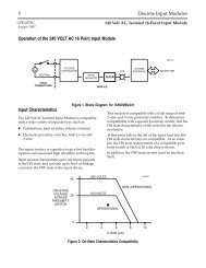
estart lowapp ARestart oddapp: ARestarts for autonumbers that do not restart ineach chapter. figure bi level 1, reset table_big level 1, reset chap_big level 1, reset1Lowapp Alwbox restart evenap:A1app_big level 1, resetA figure_ap level 1, resettable_ap level 1, reset figure level 1, reset table level 1, reset these restartsoddbox reset: 1evenbox reset: 1must be in the header frame of chapter 1. a:ebx, l 1resetA a:obx:l 1, resetA a:bigbx level 1 resetA a:ftr level 1 resetA c:ebx, l 1 reset1c:obx:l 1, reset1 c:bigbx level 1 reset1 c:ftr level 1 reset1 Reminders forautonumbers that need to be restarted manually (first instance will always be 4)let_in level 1: A. B. C. letter level 1:A.B.C. num level 1: 1. 2. 3. num_in level 1: 1. 2.3. rom_in level 1: I. II. III. roman level 1: I. II. III. steps level 1: 1. 2. 3.Chapter11 Introduction to the Hand-Held ProgrammerThe major features of the Hand-Held Programmer (catalog number IC693PRG<strong>30</strong>0) forthe <strong>Series</strong> <strong>90</strong>-<strong>30</strong>, <strong>90</strong>-20 and Micro Programmable Logic Controllers include:Creating a Statement List program, including insert, edit and delete functions.Making on-line program changes.Searching a logic program for instructions and/or machine references.Performing optional dual use checking of discrete output references wheninstructions are entered.Monitoring reference data or I/O point status while viewing the logic program.Monitoring reference data in table form in binary, hexadecimal, or decimal format.Monitoring register reference data in timer/counter format.Making on-line reference data changes.Four <strong>PLC</strong> access privilege levelsUsing the OEM protection key.Configuring I/O modules.Viewing <strong>PLC</strong> scan time, firmware revision code, and current logic memory usage.Loading, storing, and verifying program logic and configuration from/to/with the<strong>Series</strong> <strong>90</strong> Memory Card or EEPROM.Starting or stopping the <strong>PLC</strong> from any mode of operation.KeypadThe keypad on the Hand-Held Programmer consists of 42 keys, arranged as a matrix ofsix keys across by seven keys down. The keypad is color-coded for easier identificationof the different keys. Becoming familiar with the programmer keys and their functionswill increase your programming efficiency.Some of the keys have multiple uses, depending on the current operating mode andfunction. A description of the valid keys and their usage is included in chapter 2,Operation, and also in the beginning of each chapter of this manual.GFK-0402G1-1
1LCD Screen<strong>PLC</strong> CommunicationsMemor y Card InterfaceOperating ModesInformation is displayed on an LCD screen which is two lines by sixteen characters insize. The contents of the screen depends on the current operating mode and function.The intensity of the screen can be increased or decreased by inserting a Phillips-headscrewdriver into the small square opening on the right side of the programmer andturning it to the right or left, accordingly.The Hand-Held Programmer communicates with an attached <strong>PLC</strong> through an RS-422compatible port. The cable connection supplies power to the Hand-Held Programmerand indicates to the <strong>PLC</strong> that a Hand-Held Programmer is attached. Please refer tochapter 2, Operation, for cable connection information.An interface to a removable memory card is provided. This removable memory card is a<strong>Series</strong> <strong>90</strong> Memory Card (catalog number IC693ACC<strong>30</strong>3). The interface is used forstorage and/or retrieval of program logic and configuration data. Detailed informationon using the memory card to read, write, and verify data can be found in chapter 2.The Hand-Held Programmer supports four major operating modes:Mode 1. Program Mode:Program mode is used to create, alter, monitor, and debug Statement List (SL) logicprograms. Interaction (Read, Write, and Verify) with a <strong>Series</strong> <strong>90</strong> Memory Card orEEPROM is also possible in program mode. Please refer to chapter 5, Program Edit, foradditional information on using program mode.Mode 2. Data Mode:Data mode enables you to view and alter values in various reference tables. Numerousdisplay formats are also supported. Please refer to chapter 6, Reference Tables, foradditional information on using data mode.Mode 3. Protection Mode:Protection mode enables you to control access to (protect) a programmable logiccontroller, including program logic, reference data, and configuration information. Theuse of this mode is optional. Additional information on protection mode can be found inchapter 7, <strong>PLC</strong> Control and Status.Mode 4. Configuration Mode:In configuration mode, you can define the makeup of I/O modules in the <strong>PLC</strong>, includingboth those I/O modules already installed as well as those to be installed at a later time.Additional information on configuration mode can be found in chapter 3, <strong>PLC</strong>Configuration, and chapter 4, I/O Configuration.1-2 Hand-Held Programmer for <strong>Series</strong> <strong>90</strong>-<strong>30</strong>/20/Micro Programmable Controllers User’s Manual – February 1996 GFK-0402G
1Several functions may be performed independent of the current mode of operation.These functions include mode selection and starting or stopping the <strong>PLC</strong>. Please refer tochapter 7, <strong>PLC</strong> Control and Status.ReferencesThe data used in an application program is stored as either register or discretereferences. When entering a statement list program you must assign references to datain the <strong>PLC</strong> system. A reference specifies both a memory type and a precise locationwithin that memory type. For example: %I0001 specifies address 1 in discrete inputmemory and %R0256 specifies address 256 in register memory.The %I symbol is used by the <strong>PLC</strong> to distinguish machine references from nicknames(the % symbol is not entered or displayed on the HHP).The valid register and discrete references that are used with the <strong>Series</strong> <strong>90</strong>-<strong>30</strong> and <strong>Series</strong><strong>90</strong>-20 programmable logic controllers are described in the following two tables.TypeTable 1-1. Register ReferencesDescription%R The prefix %R is used to assign system register references, which will store program data such as theresults of calculations.%AI%AQThe prefix %AI represents an analog input register. This prefix is followed by the register address of thereference (for example, %AI0015). An analog input register holds the value of one analog input or othervalue.The prefix %AQ represents an analog output register. This prefix is followed by the register address ofthe reference (for example, %AQ0056). An analog output register holds the value of one analog output orother value.NoteAll register references are retained across a power cycle to the CPU.GFK-0402GChapter 1 Introduction to the Hand-Held Programmer1-3
1Table 1-2. Discrete ReferencesTypeDescription%I The %I prefix represents input references. This prefix is followed by the reference’s address in theinput table (for example, %I0121). %I references are located in the input status table, which stores the stateof all inputs received from input modules during the last input scan.A reference address is assigned to discrete input modules using the Logicmaster <strong>90</strong>-<strong>30</strong>/<strong>90</strong>-20configuration software or the Hand-Held Programmer. Until a reference address is assigned, no datawill be received from the module.%Q The %Q prefix represents physical output references. The dual use coil checking function of the HHPchecks for multiple uses of %Q references with relay coils or outputs on functions. Beginning withRelease 3 of <strong>Series</strong> <strong>90</strong>-<strong>30</strong> and Release 2 of <strong>Series</strong> <strong>90</strong>-20 firmware, you can select the level of coilchecking desired (SINGLE, WARN MULTIPLE, or MULTIPLE). Refer to Chapter 3 for more informationabout this feature.The %Q prefix is followed by the reference’s address in the output table (for example, %Q0016). %Q referencesare located in the output status table, which stores the state of the output references as last set by theapplication program. This output status table’s values are sent to output modules at the end of theprogram scan.A reference address is assigned to discrete output modules using the Logicmaster <strong>90</strong>-<strong>30</strong>/20/Microconfiguration software or the Hand-Held Programmer. Until a reference address is assigned, no data issent to the module. A particular %Q reference may be either retentive or non-retentive.%M The %M prefix represents internal references. The dual use coil checking function of the HHP softwarechecks for multiple uses of %M references with relay coils or outputs on functions. Beginning withRelease 3 of <strong>Series</strong> <strong>90</strong>-<strong>30</strong> and Release 2 of <strong>Series</strong> <strong>90</strong>-20 firmware, you can select the level of coil checking desired(SINGLE, WARN MULTIPLE, or MULTIPLE). Refer to Chapter 3 for more information aboutthis feature. A particular %M reference may be either retentive or non-retentive.%T The %T prefix represents temporary references. These references are never checked for multiple coiluse and can, therefore, be used many times in the same program even when coil use checking isenabled.Because this memory is intended for temporary use, it is never retained through power loss orRUN-to-STOP-to-RUN transitions and cannot be used with retentive coils.%S The %S prefix represents system status references. These references are used to access special <strong>PLC</strong>data, such as timers, scan information, and fault information. System references include %S, %SA,%SB, and %SC references.%S, %SA, %SB, and %SC can be used on any contacts.%SA, %SB, and %SC can be used on retentive coils -(M)-.%S can be used as a word or bit-string input reference to functions or function blocks.%SA, %SB, and %SC can be used as a word or bit-string input or output reference to functions andfunction blocks .%G The %G prefix represents global data references. These references are used to access data sharedamong several <strong>PLC</strong>s. %G references can be used on contacts and retentive coils because %G memoryis always retentive. %G cannot be used on non-retentive coils.Transitions and OverridesThe %I, %Q, %M, and %G user references have associated transition and override bits.%T, %S, %SA, %SB, and %SC references have transition bits, but not override bits. TheCPU uses transition bits for counters and transitional coils. Note that counters do notuse the same kind of transition bits as coils. Transition bits for counters are stored withinthe locating reference.1-4 Hand-Held Programmer for <strong>Series</strong> <strong>90</strong>-<strong>30</strong>/20/Micro Programmable Controllers User’s Manual – February 1996 GFK-0402G
1Retentiveness of DataIn the <strong>Series</strong> <strong>90</strong>-<strong>30</strong> model 331, 340, 341, and 351 CPU, override bits can be set. Whenoverride bits are set, the associated references cannot be changed from the program orthe input device; they can only be changed on command from the programmer. Neitherthe <strong>Series</strong> <strong>90</strong>-<strong>30</strong> model 311 or 313 CPU nor the <strong>Series</strong> <strong>90</strong>-20 model 211 CPU supportsoverriding discrete references.Data is said to be retentive if it is saved by the <strong>PLC</strong> when the <strong>PLC</strong> is stopped. Unlessotherwise stated for a particular model of CPU, the <strong>Series</strong> <strong>90</strong> <strong>PLC</strong>s preserve programlogic, fault tables and diagnostics, overrides and output forces, word data (%R, %AI,%AQ), bit data (%I, %S (%SC is retentive: not %SA or %SB), %G, fault bits and reservedbits), %Q and %M data (unless used with non-retentive coils), and word data stored in%Q and %M. %T data is not saved.%Q and %M references are non-retentive (that is, cleared at power-up when the <strong>PLC</strong>switches from STOP to RUN) whenever they are used with non-retentive coils.Non-retentive coils include coils -( )-, negated coils -( / )-, SET coils -( S )-, and RESETcoils -( R )-.When %Q or %M references are used with retentive coils, or are used as function blockoutputs, the contents are retained through power loss and RUN-to-STOP-to-RUNtransitions. Retentive coils include retentive coils -( M )-, negated retentive coils -(/M)-,retentive SET coils -(SM)-, and retentive RESET coils -(RM)-. The last use of a %Q or%M reference on a coil instruction determines its retentive state.Table 1-3. Range and Size of User References for the <strong>Series</strong> <strong>90</strong>-<strong>30</strong> <strong>PLC</strong>Models 311/313/331/340/341 CPUsModel 311/313 CPUModel 331/340/341 CPUReference Type Reference Range Size Reference Range SizeUser program memory Not applicable 3K words Not applicable 8K words (model 331)Discrete inputs %I0001 - %I0512 512 bits %I0001 - %I0512 512 bitsDiscrete outputs %Q0001 - %Q0512 512 bits %Q0001 - %Q0512 512 bitsDiscrete globals %G0001 - %G1280 1280 bits %G0001 - %G1280 1280 bitsInternal coils %M0001 - %M1024 1024 bits %M0001 - %M1024 1024 bitsTemporary coils %T0001 - %T0256 256 bits %T0001 - %T0256 256 bitsSystem status references %S0001 - %S0032 32 bits %S0001 - %S0032 32 bits%SA001 - %SA032 32 bits %SA001 - %SA032 32 bits%SB001 - %SB032 32 bits %SB001 - %SB032 32 bits%SC001 - %SC032 32 bits %SC001 - %SC032 32 bits40K words (model 341)16K words (model 340)System register references %R0001 - %R0512 512 words %R0001 - %R2048 2048 words (model 331)Analog inputs %AI001-%AI064 64 words %AI001-%AI128%AI001 - %AI1024Analog outputs %AQ001 - %AQ032 32 words %AQ001 - %AQ064%AQ001 - %AQ256%R0001 - %R9999 9999 words (model 340/341)System registers %SR001 - %SR016 16 words %SR001 - %SR016 16 words128 words (model 331)1024 words (model 340/341)64 words (model 331)256 words (model 340/341)The actual number of physical discrete inputs and outputs depends on the baseplate and modules installed.Unused references can be used as internal references in your program.For reference table viewing only; can not be referenced in a user logic program.GFK-0402GChapter 1 Introduction to the Hand-Held Programmer1-5
1Table 1-4. Range and Size of User References for the <strong>Series</strong> <strong>90</strong>-<strong>30</strong> <strong>PLC</strong>Model 351 CPUModel 351 CPUReference Type Reference Range SizeUser program memory Not applicable 40K wordsDiscrete inputs %I0001 - %I2048 2048 bitsDiscrete outputs %Q0001 - %Q2048 2048 bitsDiscrete globals %G0001 - %G1280 1280 bitsInternal coils %M0001 - %M4096 4096 bitsTemporary coils %T0001 - %T0256 256 bitsSystem status references %S0001 - %S0032 32 bits%SA001 - %SA032 32 bits%SB001 - %SB032 32 bits%SC001 - %SC032 32 bitsSystem register references %R0001 - %R9999 9999 wordsAnalog inputs %AI001-%AI2048 2048 wordsAnalog outputs %AQ001 - %AQ0512 512 wordsSystem registers %SR001 - %SR016 16 wordsFor reference table viewing only; can not be referenced in a user logic program.Table 1-5. Range and Size of User References for the <strong>Series</strong> <strong>90</strong>-20 <strong>PLC</strong>Reference Type Reference Range SizeUser program logic Not applicable 1K wordsDiscrete inputs %I001 - %I016 16 bitsDiscrete inputs, internal %I017 - %I048 32 bitsDiscrete outputs %Q0001 - %Q0016 12 bitsDiscrete outputs, internal with LED indicators %Q013 - %Q016 4 bitsDiscrete outputs, internal %Q017 - %Q048 32 bitsDiscrete globals %G0001 - %G1280 1280 bitsDiscrete internal coils %M0001 - %M1024 1024 bitsDiscrete temporary coils %T0001 - %T0256 256 bitsSystem status references %S0001 - %S0032 32 bits%SA001 - %SA032 32 bits%SB001 - %SB03232 bits%SC001 - %SC032 32 bitsSystem register references %R0001 - %R0256 256 wordsAnalog and High Speed Counter inputs %AI001-%AI016 16 wordsAnalog outputs %AQ001 - %AQ016 16 wordsSystem registers %SR001 - %SR016 16 wordsFor reference table viewing only; can not be referenced in a user logic program.1-6 Hand-Held Programmer for <strong>Series</strong> <strong>90</strong>-<strong>30</strong>/20/Micro Programmable Controllers User’s Manual – February 1996 GFK-0402G
1Table 1-6. Range and Size of User References for the <strong>Series</strong> <strong>90</strong> Micro <strong>PLC</strong>Reference Type Reference Range SizeUser program logic Not applicable 1K wordsDiscrete inputs %I001 - %I016 16 bitsDiscrete inputs, internal %I017 - %I048 32 bitsDiscrete outputs %Q0001 - %Q0016 12 bitsDiscrete outputs, internal with LED indicators %Q013 - %Q016 4 bitsDiscrete outputs, internal %Q017 - %Q048 32 bitsDiscrete globals %G0001 - %G1280 1280 bitsDiscrete internal coils %M0001 - %M1024 1024 bitsDiscrete temporary coils %T0001 - %T0256 256 bitsSystem status references %S0001 - %S0032 32 bits%SA001 - %SA03232 bits%SB001 - %SB03232 bits%SC001 - %SC03232 bitsSystem register references %R0001 - %R0256 256 wordsAnalog and High Speed Counter inputs %AI001-%AI016 16 wordsAnalog outputs %AQ001 - %AQ016 16 wordsSystem registers %SR001 - %SR016 16 wordsFor reference table viewing only; can not be referenced in a user logic program.Using the Hand-Held ProgrammerWhen power is applied to the <strong>PLC</strong>, the Hand-Held Programmer begins diagnostic testson its hardware. Once these tests are successfully completed, the Hand-HeldProgrammer can interact with the <strong>PLC</strong>.Initially, you must select an operating mode: program mode, protection mode, datamode, or configuration mode. When setting up a new system, you will normally wantto select configuration mode first, in order to configure the I/O modules to be used in thesystem. In configuration mode, you can identify which <strong>PLC</strong> backplane slots contain I/Omodules, and the size (number of Input or Output points) for each module. Based onthe size of each module, a range of discrete input and output references can either beassigned automatically by the Hand-Held Programmer, or optionally specified by theuser. The configuration of these I/O modules can be changed at any time.After configuring the I/O modules, the next step is to program the actual logicprogram. Program mode is selected for this. Once in program mode, you can create,modify, and monitor the execution of program logic instructions. The optional <strong>Series</strong><strong>90</strong> Memory Card or EEPROM can be used at any point to save or recall a particularversion of the program.While attempting to debug a logic program, you may need to view and modify data inone or more reference tables. Selecting data mode allows you to accomplish this. Oncein data mode, you can view any of the <strong>PLC</strong> reference tables in binary, hexadecimal, orsigned decimal format. Only the system register (%R) table can be viewed intimer/counter format.GFK-0402GChapter 1 Introduction to the Hand-Held Programmer1-7
1Once a system has been properly configured and its logic program is functioningcorrectly, you may want to protect parts of the system from any changes. Selectingprotection mode allows you to password-protect certain types of changes. A specialOEM protection feature can also be enabled to prevent unauthorized access.<strong>GE</strong> <strong>Fanuc</strong>a43409LCDSCREEN(TWO LINES –16 CHARACTERSPER LINE)SERIES <strong>90</strong>–<strong>30</strong>PROGRAMMABLECONTROLLERHAND HELD PROGRAMMERLDOUTOUTMSETMSETRSTMRSTTMRONDTRMODEDANDEORFNOTBLKUPCTRDNCTRRUNAIA IBQAQCMTGSFUNCDELKEYPAD7 8 9 R4 5 6 WRITE1 2 3#READVRFYSRCHINSSLOTFORMEMORYCARD0HEXDECCLRENTCABLE TO <strong>PLC</strong>IC693CBL<strong>30</strong>36 FEET (2 METERS)Figure 1-1. <strong>Series</strong> <strong>90</strong>-<strong>30</strong>/20/Micro Hand-Held Programmer1-8 Hand-Held Programmer for <strong>Series</strong> <strong>90</strong>-<strong>30</strong>/20/Micro Programmable Controllers User’s Manual – February 1996 GFK-0402G
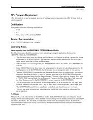
Chapter22 Operationsection level 1 1figure bi level 1table_big level 1The setup and installation of the Hand-Held Programmer is easy. The Hand-HeldProgrammer connects to a <strong>Series</strong> <strong>90</strong>-<strong>30</strong>, <strong>90</strong>-20, or Micro Programmable Logic Controllerthrough a cable attachment. The cable (catalog number IC693CBL<strong>30</strong>3, 6 feet (2 meters)long) attaches to both the Hand-Held Programmer and the programmable controllerthrough a latching connector (one on each end of the cable).Power is supplied to the Hand-Held Programmer from the <strong>PLC</strong> through a connection inthe cable. The cable connection also provides an indication to the <strong>PLC</strong> that a Hand-HeldProgrammer is attached as the programming device rather then a different programmer,since this is the same connection for the Logicmaster <strong>90</strong>-<strong>30</strong>/20/Micro programmer.Hand-heldProgrammera43107<strong>Series</strong> <strong>90</strong>–<strong>30</strong> <strong>PLC</strong>Cable(IC693CBL<strong>30</strong>3)CPUFigure 2-1. Hand-Held Programmer Connection to a <strong>Series</strong> <strong>90</strong>-<strong>30</strong> <strong>PLC</strong>Hand-heldProgrammera44549<strong>Series</strong> <strong>90</strong>–20 <strong>PLC</strong>Cable (IC693CBL<strong>30</strong>3)Figure 2-2. Hand-Held Programmer Connection to a <strong>Series</strong> <strong>90</strong>-20 <strong>PLC</strong>a45438Hand-heldProgrammer(IC693PRG<strong>30</strong>0)<strong>Series</strong> <strong>90</strong>Micro <strong>PLC</strong>Cable (IC693CBL<strong>30</strong>3)Figure 2-3. Hand-Held Programmer Cable Connection to a <strong>Series</strong> <strong>90</strong> Micro <strong>PLC</strong>GFK-0402G2-1
2Powering up the Hand-Held ProgrammerThe Hand-Held Programmer may be connected to a programmable logic controllerwhich is powered up, or it may be connected prior to power-up. When connectedduring power-up, the Hand-Held Programmer momentarily displays the followingmessages on the screen if no power-up diagnostic problems are found.ROM CHECK OKRAM CHECK OKFollowing this momentary display, the screen will display CONFIGURING SYSTEM. Theamount of time this is displayed can be as long as 7 seconds if there are intelligentmodules plugged into the I/O slots. The initial screen displayed depends upon whatwas last displayed when the Hand-Held Programmer was powered down. If the lastdisplay was a data table in data mode, that same data table will be the first screendisplayed when power is restored. If any other display in a different mode wasdisplayed, the Mode Selection screen will be displayed when the Hand-HeldProgrammer is powered up again.The following example shows the Hand-Held Programmer screen viewing the register(%R) table in timer/counter display format in data mode, with %R4 as the top referencedisplayed, when the unit was powered down.T/C R0004 0 0
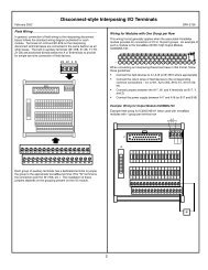
2a4<strong>30</strong>47<strong>GE</strong> <strong>Fanuc</strong>SERIES <strong>90</strong>–<strong>30</strong>PROGRAMMABLECONTROLLERHAND HELD PROGRAMMERLDOUTOUTMSETMSETRSTMRSTTMRONDTRMODEDANDEORFNOTBLKUPCTRDNCTRRUNAIA IBQAQCMTGSFUNCDEL42-KEYKEYPAD7 8 9 R#SRCH4 5 6WRITEINS1 2 3READVRFY0HEXDECCLRENTFigure 2-4. Hand-Held Programmer KeypadThe keypad on the Hand-Held Programmer is color-coded for easier identification of thedifferent keys. Becoming familiar with the programmer keys and their functions willincrease your programming efficiency.NoteSeveral keys provide access to two instructions. To access the instructionprinted on the lower half of the key, press the key twice.GFK-0402GChapter 2 Operation2-3
2Edit and Display Control KeysThe blue Edit and Display Control keys are located on the right side of the keypad. TheCLR key is red. A description of these keys is provided in the following table:Table 2-1. Edit and Display Control KeysKeyDescriptionMODESelect an HHP operating mode.RUNStart or stop the <strong>PLC</strong>.DELDelete an instruction step in program mode.Delete configuration of currently displayed slot in I/O configuration mode.Delete password at specified access level in protection mode.SRCHSearch for a given target or initiate a program check in program mode.INSBegin an instruction step insertion operation in program mode.Move between instruction steps in program mode.Move view window around currently displayed table in data mode.Select an I/O slot for viewing in configuration mode.Enter a lower or higher access level in protection mode.Move between function parameters in program mode.Invoke or abort a reference table contents change in data mode.Display a different <strong>PLC</strong> parameter, or position different binary bit for change in<strong>PLC</strong> configuration mode.Display a different module parameter or field in I/O configuration mode.Display password for lower or higher access level; view/modify OEM key inprotection mode.Move between subroutines when in Subroutine Declaration mode.ENTComplete an operation or user input.CLRAbort or cancel the current operation or user input.2-4 Hand-Held Programmer for <strong>Series</strong> <strong>90</strong>-<strong>30</strong>/20/Micro Programmable Controllers User’s Manual – February 1996 GFK-0402G
2Ladder Logic KeysThe gray Ladder Logic keys are located on the upper portion of the keypad. These keysare used to enter the program elements that make up the user’s program. A descriptionof these keys is provided in the following table:Table 2-2. Ladder Logic KeysKeyDescriptionLDOUTOUTMSETMSETRSTMRSTProgram a boolean logic instruction in program mode.DANDEORFNOTBLKFUNCProgram a function or function block instruction in program mode.Program TMR, ONDTR, UPCTR, DNCTR function blocks in program mode.TMRONDTRUPCTRDNCTRChange data mode display format to timer/counter; automatically selectregister table if not displayed in data mode. (This does not apply to theFUNC key.)A IAIB QAQCMTGSRSpecify a memory reference type in program and data mode.I/AI and Q/AQ and G specify module types in configuration mode.AIAIBQAQCMTSpecify a binary, decimal (possible signed) or hexadecimal value in programand data mode.DANDEORFNOTSpecify a slot number, reference address, point count or <strong>PLC</strong> parametervalue; value format may be either binary, signed decimal, or hexadecimal inconfiguration mode.Specify the alpha characters of a 1 - 4 digit hexadecimal password value.#Specify an instruction step in program mode.Override, or cancel the override on, a discrete reference in data mode.Indicate a new rack/slot number (GOTO) in configuration mode.Zoom into or out of subroutine logic.GFK-0402GChapter 2 Operation2-5
2Numeric KeysThe white Numeric keys are located on the lower left side of the keypad. They includethe keys for the numerals 0 through 9, the –/+ key, and the HEX/DEC key. Adescription of these keys is provided in the following table:Table 2-3. Numeric KeysKeyDescription0 1 2 34 5 6 78 9– +HEXDECSpecify a binary, decimal (possible signed), or hexadecimal value inprogram and data mode.Specify a slot number, reference address, point count, or <strong>PLC</strong> parametervalue; value format may be either binary, signed decimal, or hexadecimalin configuration mode.Specify a 1 - 4 digit hexadecimal password value in protection mode.Specify a binary, decimal (possible signed), or hexadecimal value inprogram and data mode.Toggle <strong>PLC</strong> configuration parameter setting in configuration mode.Toggle between run and stop mode in any mode.Specify a signed decimal or hexadecimal constant in program mode.Change display format between binary, signed decimal, and hexadecimalin data mode.Change display format between decimal, hexadecimal, and 8-bit binary inconfiguration mode.Program Transfer KeysThe Program Transfer keys are located in the blue shaded area in the lower right portionof the keypad. They include the READ/VERIFY and WRITE keys.Table 2-4. Program Transfer KeysKeyDescriptionREADVRFYRead or verify the memory card or system EEPROM in program mode.Read configuration of module currently installed in slot.WRITEWrite the memory card or system EEPROM in program mode.2-6 Hand-Held Programmer for <strong>Series</strong> <strong>90</strong>-<strong>30</strong>/20/Micro Programmable Controllers User’s Manual – February 1996 GFK-0402G
2Power-Up Key SequencesThe key sequences listed below can be used during power-up to provide additional start-upinstructions for the <strong>PLC</strong>, or to override the previous configuration. When used to overridethe previous configuration these keys must be depressed simultaneously while the ROMCHECK OK & RAM CHECK OK screen is being displayed and held depressed until themode screen is displayed on the HHP. (The keys must be pressed simultaneously until theROM CHECK OK, RAM CHECK OK message is removed from the screen.)During power-up, the <strong>PLC</strong> may be instructed to totally clear all data stored within it. Thisincludes program logic, data tables, configuration, passwords, and the OEM key. To do this,press and hold the CLR and M/T keys simultaneously while the <strong>PLC</strong> is powering up. AROM CHECK OK or RAM CHECK OK message is displayed on the Hand-HeldProgrammer screen upon receiving power. Double key strokes must be held until after theROM CHECK OK and RAM CHECK OK message is cleared. Note that power-up sequencesfrom the HHP are not processed for warm start powerups.CautionDo not press the CLR and M/T keys to clear memory if an OEM programis in RAM memory. All configuration data and logic will be lost.The <strong>PLC</strong> can be configured to download a logic program during start-up from EEPROM(located in the EEPROM socket on the baseplate of the Model 311 and in the CPU modulein a Model 331) to RAM, instead of running from the existing program in RAM. You canoverride this option when testing changes to the program so that the program in RAM isretained, and not overwritten by the program in EEPROM. To use RAM memoryregardless of the configuration, press LD and NOT keys simultaneously while the <strong>PLC</strong> ispowering up.The <strong>PLC</strong> can be configured to power up in RUN or STOP mode, or in the same mode itwas powered down in. This configured state can be overridden to ensure that the <strong>PLC</strong> willpower up in STOP mode, regardless of the configuration. To do this, press NOT and RUNsimultaneously during power-up until the RAM CHECK OK, ROM CHECK OK message isdisplayed on the screen.Table 2-5. Power-Up OptionsKey SequenceDescriptionCLRLDC MTFNOTTotally clears all data stored within the <strong>PLC</strong>, including program logic, datatables, configuration, passwords, and the OEM key. Do not use this functionif an OEM program is in RAM memory, as all configuration data andlogic will be lost.Prevents the <strong>PLC</strong> during power-up from downloading a program from EE-PROM to RAM and puts the CPU in the STOP mode. Use RAMmemory regardless of the configuration.FNOTRUNEnsures that the <strong>PLC</strong> powers up in the STOP mode.GFK-0402GChapter 2 Operation2-7
2Special Key SequencesTable 2-6. Special Key Sequences#Key Sequence– + 9 99 DELDescriptionClear all program logic instruction steps from memory without affectingany other memory, such as data or configuration (only when in programmode, will not work in program insert mode).SRCH # – + 1Begin the program check function (only when in program mode, will notwork when in program insert mode).ENTSelecting an Operating ModeIn general, most functions are available only in a single mode of operation. To interactwith a particular function, the correct mode of operation must first be selected.1. Press the MODE key to select a new mode of operation. After pressing MODE, thefollowing initial screen will be displayed:_ 1. PROGRAM
24. Press the –/+ key again to toggle the selection to stop mode:STOP MODE
2CautionIf EEPROM is selected and a PROM is not in the socket or a blankPROM is in the socket, on a power-up cycle a blank program will beplaced into the RAM memory, therefore the program in RAM will be lost.EEPROM and EPROM memory chips are available from <strong>GE</strong> <strong>Fanuc</strong>. Catalog numbers forthese devices are listed in the following table.Catalog NumberTable 2-7. EEPROM and EPROM Memory Catalog NumbersDescription<strong>GE</strong> <strong>Fanuc</strong>PROMPart NumberIC693ACC<strong>30</strong>5 (Qty 4) 28C256 EEPROM, 350ns 44A725999-000 XICORXICORThird Party SourceVendor Part NumberX28C256P orX28C256-25IC693ACC<strong>30</strong>6 (Qty 4) 32Kx8 UV EPROM, 150ns 44A723379-000 NEC PD27C256AD-15AtmelToshibaHitachiAMDIntelAT27C256-15DC1TC57256AD-15HN27C256AG-15AM27C256-150DCTD27C256A-1Installing a Blank EEPROM/EPROMUse the following procedure for installing a blank EEPROM or EPROM in a <strong>Series</strong> <strong>90</strong>-<strong>30</strong>or <strong>Series</strong> <strong>90</strong>-20 <strong>PLC</strong>.CautionYou must be careful when installing a blank EEPROM or EPROM inthe PROM socket of the CPU in a <strong>Series</strong> <strong>90</strong>-<strong>30</strong> or <strong>Series</strong> <strong>90</strong>-20 or theprogram in RAM memory will be lost.1. Configure the CPU toPRG SRC RAM and REG SRC RAM(see NOTE at end of this procedure)2. Remove power from the <strong>PLC</strong>.3. Remove the CPU from its socket on the baseplate.4. Remove the faceplate and LED lens cover from the CPU. The PROM socket is nowaccessible at the bottom of the CPU board.5. Turn the screw at the center top of the socket counter clockwise so that the slot linesup with the O. This allows an EEPROM or EPROM to be inserted.2-12 Hand-Held Programmer for <strong>Series</strong> <strong>90</strong>-<strong>30</strong>/20/Micro Programmable Controllers User’s Manual – February 1996 GFK-0402G
2<strong>Series</strong> <strong>90</strong> Memory Card6. Insert the EEPROM or PROM into the socket with the notch facing the screw.7. Turn the screw clockwise so that the slot lines up with the C. The EEPROM orEPROM is now locked into the socket.8. Set the jumper plug at the bottom of the socket for EEPROM (3-2) or PROM (2-1), asrequired.9. Replace the faceplate.10. Insert the CPU into its connector in the baseplate.11. Turn-on power to the <strong>PLC</strong>.12. The CPU can now be configured toPRG SRC EEPROM and REG SRC EEPROMNoteIf not configured for Program (PRG) and Register (REG) from RAMwhen power is applied after a blank EEPROM is inserted, the contentsof the blank PROM will be loaded into the RAM memory. The CPU canbe forced to load Program and Registers from RAM, if on power-upusing the Hand-Held Programmer the LD and NOT keys are depressedsimultaneously and held depressed during power-up until the MODEselection menu is displayed.In addition to EEPROM a <strong>Series</strong> <strong>90</strong> Memory Card inserted into the Hand-Held Programmermay be used to save, retrieve or verify program logic data and configuration data containedon it versus the actual <strong>PLC</strong> contents. The <strong>Series</strong> <strong>90</strong> Memory Card is not supported by theModel 351 CPU.If the memory card or EEPROM has not been properly inserted before attempting a write,read, or verify operation, the absence of the card or EEPROM will be detected as an errorand an error message will be displayed.The <strong>PLC</strong> must also be stopped and must not be scanning I/O before you can perform amemory card or EEPROM operation. If you attempt to write, read, or verify data when the<strong>PLC</strong> is running, a RUNNING error message will be displayed on the screen. You must firststop the <strong>PLC</strong> before attempting the desired operation again. Also, when the CPU isconfigured for DO I/O, a DO I/O error message will be displayed on the screen. Change theCPU configuration STOP MD DO I/O to STOP MD NO I/O.It is possible that a communications error between the Hand-Held Programmer and thememory card may occur during a write, read, or verify operation. If this occurs, theoperation will be canceled and a COMM ER error message will be displayed. Make surethat the memory card is properly seated in the Hand-Held Programmer slot, beforeattempting the operation again.The following screen format is used to write, read, or verify the memory card or EEPROM.Table 2-8. Read/Write/V erify <strong>Series</strong> <strong>90</strong> Memory Card or EEPROMOperation Device
2Operation:The operation field indicates the particular operation which is to be performed on thedestination device, MEM CARD or EEPROM. Its modes of operation are listed below,along with a description of each.MODE OF OPERATIONDESCRIPTION————————————————— ————————————————————————————————————————————————————————READRead the contents of the memory card or EEPROM into RAM.WRITE Write the contents of RAM to the memory card or EEPROM.VERIFY Verify contents of the memory card or EEPROM with RAM.Device: This field identifies the destination device, which in this case, is the <strong>Series</strong> <strong>90</strong>Memory Card or EEPROM. This field may also function as an errormessage window if you attempt a read, write, or verify operation without amemory card or EEPROM properly inserted.
2Storing RAM to the Memory Card or EEPROMTo store (write) a copy of the contents of RAM memory into a <strong>Series</strong> <strong>90</strong> Memory Card orEEPROM, follow this procedure: (Note: for the Model 340 or 341, use steps 1, 2, an 3; for allother models use only steps 1 and 3)1. In program mode, press the WRITE key:WRITE MEM CARD
2Verifying RAM with the Memory Card or EEPROMTo manually verify the contents of a previously programmed <strong>Series</strong> <strong>90</strong> Memory Card orEEPROM with the <strong>PLC</strong>’s RAM memory, follow this procedure:1. In program mode, press the READ/VERIFY key twice:VERIFY MEM CARD
2Program/Configuration PortabilityPrograms, configuration, and registers can be transported from one model to a differentmodel of a <strong>Series</strong> <strong>90</strong>-<strong>30</strong> or <strong>Series</strong> <strong>90</strong>-20 CPU. This can be done using either an EEPROM,a MEM card, or a UVEPROM (if copied from an EEPROM). In this discussion thesedevices will be referred to as the device, since all of the rules apply equally to all three.The model of the CPU from which the device was written is referred to as the sourceCPU. The model of the CPU into which the contents of the device will be read isreferred to as the target CPU.There are certain restrictions on this portability as listed below:1. Programs must be compatible with the target CPU. That is, they must not havereferences to addresses which do not exist in the target CPU and they must fit intothe size restrictions of the target CPU. If non-valid references are attempted and thiserror is detected by the <strong>PLC</strong>, a PRG ERR message will be reported to the user by theHHP.2. Configurations must be compatible with the target CPU. That is, they must notcontain modules not supported by the target CPU nor have modules in racks notsupported by the target CPU. If this error is detected by the <strong>PLC</strong>, then a CFG ERRmessage will be reported to the user by the HHP.3. When reading configurations from a model which supports more slots into a CPUwhich supports fewer slots, the slots higher then those supported by the target CPUmust be EMPTY.4. When reading configurations from a model which supports fewer slots into a CPUwhich supports more slots, the slots in the target CPU beyond those supported bythe source CPU will be set to EMPTY.5. When reading registers from a CPU which supports a different number of registersthen the target CPU, those registers higher then those supported by the smaller CPUwill be ignored.6. When configuration is read from one CPU model into a different model, the <strong>PLC</strong>must change the CPU model in the configuration to match the target model. Afterthis configuration has been read and the model changed, the contents of theconfiguration in RAM memory cannot be verified with the contents of theconfiguration on the device.7. The Model 351 CPU does not support the <strong>Series</strong> <strong>90</strong> Memory Card and its flashmemory is not removeable. Transporting programs to and from Model 351 CPUs isdone using Logicmaster -<strong>30</strong>/20/Micro software. With this exception, the followingdiscussions on reading the device also apply to reading data from the Model 351 flash memory.A list of the error messages which can be produced as a result of attempting to read adevice can be found in Chapter 9 in this manual along with a description of possiblecauses and corrective actions.If the entire contents of the device are not read, then the data which was not readremains intact within the <strong>PLC</strong>. For example, if only the program is being read, then theconfiguration and registers will remain unchanged by the attempted read, regardless ofany errors encountered while reading the program.Examples of program/configuration compatibility operations with the HHP are shownon the following pages.GFK-0402GChapter 2 Operation2-17
2Reading the entire deviceTo read (load) the entire contents of an EEPROM previously programmed from the sameCPU model follow this procedure:In PROGRAM mode, press theREADVRFYkey:READ MEM CARD
2Reading Program Logic OnlyIf desired, you can read only the program logic from the device, ignoring theconfiguration and register data which was saved on the device. To do this use thefollowing procedure:In PROGRAM mode, press theREADVRFYkey:READ MEM CARD
2If an error is detected, the contents of the <strong>PLC</strong> logic program will be cleared. If theattempt had been to read more then one type of data (for example, program andregisters), then each of those types of data would have been cleared upon detection ofan error.Differing CPU ModelsIf the CPU model of the source <strong>PLC</strong> is not the same as the CPU model of the target CPU,then the model must be changed when the configuration is read from the device. Forexample, the device may have been written using a <strong>Series</strong> <strong>90</strong>-20 model 211 CPU and thecontents of the device are being read into a <strong>Series</strong> <strong>90</strong>-<strong>30</strong> model 311 CPU. This changingof the CPU model type applies ONLY when reading configuration.To read the contents of a device from a different CPU model, use the following steps:In PROGRAM mode, press theREADVRFYkey:READ MEM CARD
2To change the model of the configuration being read into the <strong>PLC</strong> (the device contentswill be unaffected):Press the ENT key:READ OK
Chapter33 <strong>Series</strong> <strong>90</strong>-<strong>30</strong>/20 <strong>PLC</strong> Configurationsection level 1 1figure bi level 1table_big level 1A number of <strong>PLC</strong> parameters are user-configurable. Each of these parameters has adefault value which, for many users, will not need to be changed. These parameters,their selections and default selections are shown in the following table.NoteThis chapter describes configuration for the <strong>Series</strong> <strong>90</strong>-<strong>30</strong> and <strong>90</strong>-20 <strong>PLC</strong>s.See Chapter 4 for configuration information for the Micro <strong>PLC</strong>.Table 3-1. User-Configurable <strong>PLC</strong> ParametersParameter Selections Default ValueKey clickTime of day clock(Not available on Model 311/321,Model 313/323, or Model 211)ON (ENABLED)OFF (DISABLED)MonthDayYearHourMinuteSecondOFFProgram sourceRegister sourcePower-up modeActive Constant Sweep ModeRAMEEPROMRAMEEPROMRUNSTOPSAME PDDISABLEENABLERAMRAMSAME PDDISABLEActive Constant Sweep Setting 5 - 200 msec 100 msecConfigured Constant Sweep ModeDISABLEENABLEDISABLEConfigured Constant Sweep Setting 5 - 200 msec 100 msecI/O scan in stop modeDual use checkingNO I/ODO I/OSINGLEWRN MULMULTNO I/OSINGLEPort idle time 1 - 60 seconds 10 secondsGFK-0402G3-1
3Table 3-1. User-Configurable <strong>PLC</strong> Parameters (continued)Parameter Selections Default ValueBaud rate <strong>30</strong>0600120024004800960019.2k19.2kData bits7 BITS8 BITS8 BITSStop bits1 BIT1 BIT2 BITSParityODDODDNONEEVENModem turnaround time 0 to 255 counts 0Disable passwordsENABLEENABLEDISABLECPU ID 6 ASCII characters 0 - F 000000Default I/O ConfigurationENABLEENABLEDISABLEChecksum Words Per Sweep 8 through 32 8This chapter describes how each parameter is configured.The initial screen displayed in configuration mode is the last one viewed the previoustime configuration mode was selected, since the <strong>PLC</strong> was powered up. If this is the firsttime configuration mode was entered, slot 1 of rack 0 (Model 331/340/341/351 CPU rack)or slot 0 of rack 0 (Model 311/313) is displayed.Entering Configuration ModeIn order to view and/or change the <strong>PLC</strong> parameters, you must first select theconfiguration mode of operation.1. To select configuration mode, press the MODE key to display the operating modeselections._ 1. PROGRAM
33. Press the ENT key to enter the new mode.The first screen displayed will be R0:00 for Model 311/321 and 313/323 or R0:0l for Model331/340/341/351 and Model 211 (Model 211 is <strong>Series</strong> <strong>90</strong>-20). This is the first <strong>PLC</strong>configuration screen displayed. Use the z ‡ keys to view the other parameters andthe –/+ key to select the variable for a parameter.R0:00 <strong>PLC</strong>
3Display FormatThe following screen format is used for configuring the <strong>PLC</strong> parameters:Table 3-3. Configuration Screen FormatRRack# :Slot# Module Type or Message<strong>PLC</strong>StateParameter Label & Parameter ValueRack #: Slot #: The rack #: slot # field indicates the currently displayed rack and slot.For configuration purposes, the model 311 and 313 CPU module is embeddedin the backplane. The Model 331/340/341/351 and Model 211CPU module is always located in slot 1 of rack 0.Module Type or Message: The module type or message field normally displays thedesignation <strong>PLC</strong>, indicating that <strong>PLC</strong> parameters are being configured.This field also functions as an error message window.<strong>PLC</strong> State: The <strong>PLC</strong> state field indicates whether the <strong>PLC</strong> is currently stopped or isrunning (executing a program). A leading < character, followed by S ifthe <strong>PLC</strong> is stopped or R if it is running, indicates the state of the <strong>PLC</strong>.Parameter Label: The parameter label field contains a text string which is used as aprompt to the user for a particular parameter.Parameter Value: The parameter value field contains a value input by the user.Locating a Slot or Rack and <strong>PLC</strong> ParametersFor configuration purposes, the Model 311/321 and 313/323 CPU (slot 0 of rack 0) isembedded in the backplane. The Model 331/340/341/351 and 211 CPU module is alwayslocated in slot 1 of rack 0.The Up and Down cursor keys can be used to view the previous or next slot in the rack.If the current slot is at the end of the current rack, the next slot displayed will be theadjacent slot in the next/previous rack. For Model 211 slot 2 is always inputs, slot 3 isalways outputs and slot 4 is always High Speed Counter.The # key, in conjunction with a slot number, can be used to go to a particular slot, asshown in the following example.1. When configuration mode is selected, the first screen displayed is the last slotviewed the last time this mode was entered (except after power-up). For thisexample, assume that slot 3 of the main rack was the last slot viewed:R0:03 EMPTY
32. Press the # key to begin the GOTO operation:R0:03 EMPTY
3Program Source ParameterAt power-up, you can specify that the program copy in RAM should be used, or that theprogram copy in EEPROM should be loaded into RAM and used. This can be helpfulwhen you are running a program without battery backup.Use the Right cursor key to scroll through the <strong>PLC</strong> parameters until the program source(PRG SRC) parameter is displayed. Then, use the –/+ key to toggle the selectionbetween RAM and EEPROM. By default, the program copy in RAM will be used.Register Source ParameterAt power-up, you can specify that the register table (R) values in RAM should be used, orthat the register table initialization values in EEPROM should be loaded into RAM andused. This is also useful when you are running a program without battery backup.Use the Right cursor key to scroll through the <strong>PLC</strong> parameters until the register source(REG SRC) parameter is displayed. Then, use the –/+ key to toggle the selectionbetween RAM and EEPROM. By default, the register table copy in RAM will be used.NoteSetting this parameter to EEPROM has no effect unless Program Sourceis also set to EEPROM.Power-Up Mode ParameterThe <strong>PLC</strong> can be configured to always power up in one of these modes:1. RUN mode.2. STOP mode.3. The SAME mode Powered Down in (SAME PD).STOP mode should be used when the program is not fully debugged or requires manualintervention during start-up. RUN mode, on the other hand, should be used whenmanual intervention is neither required nor allowed. The normal selection for thisparameter is to power up in the SAME mode that the system was powered down in.Use the Right cursor key to scroll through the <strong>PLC</strong> parameters until the power-up mode(PU MODE) parameter is displayed. Then, use the –/+ key to toggle the selectionbetween STOP, RUN, and SAME PD.By default, the <strong>PLC</strong> will power up in the SAME PD mode powered down in.Active Constant Sweep Mode ParameterThe <strong>PLC</strong> can be configured during RUN mode to use a constant amount of time persweep. The active constant sweep mode parameter gives you the ability to enable ordisable the constant sweep mode while the program is running, and have the effectsnoticed immediately. This parameter can be used to toggle the sweep mode of the <strong>PLC</strong>without changing the configured constant sweep mode parameter. The active constantsweep mode parameter, once changed, is only valid during the current RUN mode.3-6 Hand-Held Programmer for <strong>Series</strong> <strong>90</strong>-<strong>30</strong>/20/Micro Programmable Controllers User’s Manual – February 1996 GFK-0402G
3When going from STOP to RUN mode, the configured sweep mode parameter value iscopied to the active sweep mode parameter.Use the Right cursor key to scroll through the <strong>PLC</strong> parameters until the active constantsweep mode (ACT CNSW) parameter is displayed. Then, use the –/+ key to toggle theselection between DISABLE and ENABLE. By default, the <strong>PLC</strong> will execute every sweepas fast as possible.Active Constant Sweep Setting ParameterIf the Constant Sweep Mode is enabled in the <strong>PLC</strong> during RUN mode, then the ActiveConstant Sweep Setting parameter can be used to adjust the sweep time. This allowsyou to fine tune the sweep time while the <strong>PLC</strong> is running a program. Changing thisparameter does not affect the Configured Constant Sweep Setting parameter. TheActive Constant Sweep Setting is only valid during the current RUN mode, as long asActive Constant Sweep Mode is enabled. Upon going from STOP to RUN mode, theConfigured Sweep Setting parameter value is copied to the Active Sweep Settingparameter. If the Active Constant Sweep mode is disabled, this parameter is ignored.The active constant sweep value can range between 5 and 200 milliseconds.Use the Right cursor key to scroll through the <strong>PLC</strong> parameters until the Active ConstantSweep setting (ACT CONS TM) parameter is displayed. To set the active sweep time,enter a value between 5 and 200 milliseconds, and press the ENT key. The defaultsetting is 100 milliseconds.Configured Constant Sweep Mode ParameterThe <strong>PLC</strong> can be configured to use a constant amount of time per sweep. The ConstantSweep Mode parameter should be enabled when I/O points or register values must bepolled at a constant frequency, such as in control algorithms. The Configured SweepMode parameter can be overridden by the Active Constant Sweep Mode parameterduring RUN mode, but upon going from STOP to RUN mode, the Configured SweepMode parameter value is copied to the Active Constant Sweep Mode parameter (seeActive Constant Sweep Mode Parameter). The Configured Sweep Mode parameter canonly be edited during STOP mode.Use the Right cursor key to scroll through the <strong>PLC</strong> parameters until the ConfiguredConstant Sweep mode (CFG CNSW) parameter is displayed. Then, use the –/+ key totoggle the selection between DISABLE and ENABLE. By default, the <strong>PLC</strong> will executeevery sweep as fast as possible.Configured Constant Sweep Setting ParameterIf the Configured Constant Sweep mode is enabled in the <strong>PLC</strong>, the sweep time valuemust also be selected. The Configured Constant Sweep Setting parameter can beoverridden by the Active Constant Sweep Setting parameter during RUN mode, butupon going from STOP to RUN mode, the Configured Constant Sweep Settingparameter value is copied to the Active Constant Sweep Setting parameter. This allowsyou to maintain a configured setting, while fine tuning the setting during RUN modewith the active Constant Sweep Setting parameter. If the Configured Constant Sweepmode is disabled, this parameter is ignored. The Configured Constant Sweep value canrange between 5 and 200 milliseconds.GFK-0402GChapter 3 <strong>Series</strong> <strong>90</strong>-<strong>30</strong>/20 <strong>PLC</strong> Configuration3-7
3Use the Right cursor key to scroll through the <strong>PLC</strong> parameters until the ConfiguredConstant Sweep Setting (CFG CONS TM) parameter is displayed. To set the sweep time,enter a value between 5 and 200 milliseconds, and press the ENT key. The defaultsetting is 100 milliseconds.I/O Scan in Stop Mode ParameterBy default, the <strong>PLC</strong> will not scan I/O in stop mode. Enabling this parameter, however,allows you to debug and test input and output wiring without a control programinstalled.Use the Right cursor key to scroll through the <strong>PLC</strong> parameters until the I/O scan in stopmode (STOP MD) parameter is displayed. Then, use the –/+ key to toggle the selectionbetween NO I/O and DO I/O.Dual Use Checking ParameterThe dual use checking parameter allows you to select whether or not %M and %Qreferences should be restricted to single use as outputs within the user logic program.When enabled, the system will not allow you to assign the same reference to twodifferent coils.NoteThis feature is not editable in a Model 351 CPU, since this parameterapplies to the user program, not the configuration.Use the Right cursor key to scroll through the <strong>PLC</strong> parameters until the dual usechecking (COIL US) parameter is displayed. Then, use the –/+ key to toggle betweenSINGLE, WRN MUL, and MULT. By default, WRN MUL is enabled. When togglingfrom MULT to SINGLE or WRN MUL, the program is checked for multiple coil usage. Ifmultiple coils are detected, you can go to program mode and find the multiple coil usagewith the SRCH, #, –1 key sequence. When going to SINGLE, the transition is notallowed; when going to WRN MUL, the transition is allowed. SINGLE check preventsusing the same %M or %Q coil reference in two or more locations in the program. WRNMUL allows multiple coil uses of the same %M or %Q reference, but provides a warningscreen to the user that this is being done, and MULT allows multiple coil usage without awarning.NoteWhen an instruction is added and the coil use warning message isdisplayed, the warning message should be verified with the searchfunction. It is possible that the use warning message is displayed eventhough the coil is used only once in the program.The <strong>PLC</strong> parameters described on the following pages are controlled by the Hand-HeldProgrammer, but do not affect its operation. They are used for communications throughthe power supply port with devices other than the HHP.3-8 Hand-Held Programmer for <strong>Series</strong> <strong>90</strong>-<strong>30</strong>/20/Micro Programmable Controllers User’s Manual – February 1996 GFK-0402G
3Port Idle Time ParameterBaud Rate ParameterData Bits ParameterStop Bits ParameterParity ParameterThis parameter allows you to specify the maximum amount of time a communicationsattachment to the <strong>PLC</strong> can be idle (no communications) before the <strong>PLC</strong> assumes thatcommunications has either been lost or terminated. The maximum allowable idle timecan range between 1 and 60 seconds, inclusive. The default value is 10 seconds.Use the Right cursor key to scroll through the <strong>PLC</strong> parameters until the port idle time(IDLE TM) parameter is displayed. To specify the amount of allowable idle time, enter avalue between 1 and 60 seconds, inclusive, and press the ENT key.The baud rate assigned to the communications port is selectable. The baud ratessupported are <strong>30</strong>0, 600, 1200, 2400, 4800, 9600, and I will add the Range function19.2kwith the default setting at 19.2k.Use the Right cursor key to scroll through the <strong>PLC</strong> parameters until the baud rate(BAUD RT) parameter is displayed. Then, use the –/+ key to toggle the selectionbetween the baud rates supported.You can select either 7 or 8 data bits per word for <strong>Series</strong> <strong>90</strong> Protocol (SNP)communications. The default value is 8 data bits per word.You can also select either 1 or 2 stop bits for <strong>Series</strong> <strong>90</strong> protocol communications. Thedefault value is 1 stop bit.Use the Right cursor key to scroll through the <strong>PLC</strong> parameters until the stop bits (STOPBT) parameter is displayed. Then, use the –/+ key to toggle the stop bits selectionbetween 1 BIT and 2 BITS.The selections for parity in <strong>Series</strong> <strong>90</strong> protocol communications include even, odd, and noparity. Odd parity is the default value parity.Use the Right cursor key to scroll through the <strong>PLC</strong> parameters until the parity parameteris displayed. Then, use the –/+ key to toggle the parity selection between ODD,NONE, and EVEN.Modem Turnaround Time ParameterThis parameter allows you to configure the turnaround delay time required for aparticular modem. You must specify a given number of counts, where each countrepresents 0.01 seconds (10 msec). The number of counts can range from 0 (0 msecdelay) to 255 (2.55 sec delay). Use 0 (zero) for direct connection with no turnaroundtime.Use the Right cursor key to scroll through the <strong>PLC</strong> parameters until the modemturnaround time (MDM TAT) parameter is displayed. To specify the number of counts,enter a value between 0 and 255, inclusive, and press the ENT key.GFK-0402GChapter 3 <strong>Series</strong> <strong>90</strong>-<strong>30</strong>/20 <strong>PLC</strong> Configuration3-9
3Password (ENABLE/DISABLE) ParameterThis parameter lets you enable or disable the password parameter. The default for thisparameter is ENABLE. See Chapter 7 for more information on passwords.CPU ID Parameters ID1, ID2, and ID3The next <strong>PLC</strong> parameter you can configure is CPU ID parameter ID1. This parameter isthe first of three consecutive parameters used to input a network identification name ona <strong>Series</strong> <strong>90</strong> protocol network.Each parameter is a 4-digit hexadecimal number. The four hexadecimal digitscorrespond to two ASCII characters; thus, a 6-character identifier is entered twocharacters at a time. If the total identifier consists of less then six characters, all trailingcharacters must be set to the NULL character (ASCII 00H). By default, the <strong>PLC</strong> is notassigned a network name; all characters are set to NULL.Use the Right cursor key to scroll through the <strong>PLC</strong> parameters until the first IDparameter is displayed. Enter the key sequence of the ASCII-hex numbers whichcorrespond to the network name you wish to specify. Then, press the ENT key. Followthis same procedure for parameters ID2 and ID3.This parameter has three inputs ID1, ID2, ID3 which combine together to form a 6character ASCII word which gives this CPU a unique identification value. This value isused to identify this CPU when it is connected to a communications bus network whichhas more then one CPU connected on the network.Assume that the network name ABCDE is to be assigned to the <strong>PLC</strong>. This namecorresponds to the ASCII-HEX sequence 41-42-43-44-45-00.ID1 = 4142 which equals ABID2 = 4344 which equals CDID3 = 45-00 which equals EAlso assume that the previous parameter, MODEM TURNAROUND TIME, is currentlybeing viewed. Press the ‡ key two times to select the ID1 parameter.Initial display:R0:01 <strong>PLC</strong>
3Press the ENT key: RO:01 <strong>PLC</strong>
3Press thekey two times:R0:01 <strong>PLC</strong>
3verify may not produce the same results if STOREd, since modules may have beenphysically added since the Logicmaster <strong>90</strong>-<strong>30</strong> configuration was LOADed from the <strong>PLC</strong>Checksum Words Per SweepThis parameter allows you to select the number of words per sweep to bechecksummed. The selectable range is from 8 to 32 words (any number of wordsbetween 8 and 32).Canceling a Configuration OperationThe CLR key can be used to cancel the current parameter modification and restore theoriginal setting. When attempting to change the configuration of a <strong>PLC</strong> parameter, avalid value must be entered. If an invalid value is specified, the configuration requestwill be refused and a DAT ERR message will be displayed.In a GOTO operation, described in the beginning of this chapter, the CLR key can beused to cancel the operation and remain on the currently viewed slot. If a slot numberhas already been entered, press the CLR key to erase the current input and remain inslot selection mode. Pressing the CLR key a second time cancels the GOTO operation. Ifno user input had been specified when the CLR key is pressed the first time, only asingle press of the CLR key is required to cancel the GOTO operation.Exiting Configuration ModeTo exit the <strong>PLC</strong> configuration function, press the MODE key. The mode selection screenwill be displayed.GFK-0402GChapter 3 <strong>Series</strong> <strong>90</strong>-<strong>30</strong>/20 <strong>PLC</strong> Configuration3-13
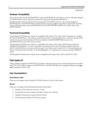
Chapter44 <strong>Series</strong> <strong>90</strong> Micro <strong>PLC</strong> Configurationsection level 1 1figure bi level 1table_big level 1The <strong>Series</strong> <strong>90</strong> Micro <strong>PLC</strong> can be configured and programmed using the <strong>Series</strong><strong>90</strong>-<strong>30</strong>/20/Micro Hand-Held Programmer (IC693PRG<strong>30</strong>0).Configuration and programming using the Hand-Held Programmer must be done withthe Hand-Held Programmer (HHP) attached to and interfacing with the <strong>PLC</strong>.This chapter has two Sections. Section 1 describes configuration of the Micro <strong>PLC</strong> CPUparameters; Section 2 describes configuration of the High Speed Counter that is builtinto the Micro <strong>PLC</strong>.For detailed information about the <strong>Series</strong> <strong>90</strong> Micro <strong>PLC</strong>, refer to GFK-1065, the <strong>Series</strong> <strong>90</strong>Micro <strong>PLC</strong> User’s Manual.a45452I1 I2 I3 I4 COM1I5 I6 I7 I8COM224 VDC OUTPWROKRUNINPUT24 VDC INPUT POS/NEG<strong>GE</strong> <strong>Fanuc</strong>SERIES <strong>90</strong> MICRO12 3 4 5 6 7 8OUTPUTPROGRAMMABLE CONTROLLER~85–265VACL H~24 VDC. 120 / 240 VAC N.O. RELAY OUTQ1 COM1 Q2 COM2 Q3 Q4 Q5 Q6 COM3Figure 4-1. <strong>Series</strong> <strong>90</strong> Micro Programmable Logic ControllerGFK-0402G4-1
4Section 1: Micro <strong>PLC</strong> ConfigurationTable 4-1 lists all parameters for the Micro <strong>PLC</strong> except those concerning the High SpeedCounters (see Section 2 for details on configuring the High Speed Counters).Parameters that are displayed for the user’s information only are denoted not editablein the description.Table 4-1. Micro <strong>PLC</strong> ParametersParameter Description Possible Values Default ValueI/OScan-StopDetermines whether I/O is to be scanned while the <strong>PLC</strong>is in STOP modeYESNOPwr Up Mode Selects power up mode. LASTSTOPRUNLogic From Source of logic when the <strong>PLC</strong> is powered up RAMPROM (flash memory)RegistersPasswordsSelects source of register data when the <strong>PLC</strong> is poweredup.Determines whether the password feature is enabled ordisabled. (Note: If passwords are disabled, the only wayto re-enable them is to clear the Micro <strong>PLC</strong> memory bypower cycling the unit with the battery removed.)RAMPROM (flash memory)ENABLEDDISABLEDBaud Rate Data transmission rate (in bits per second) <strong>30</strong>0 4800600 96001200 192002400Data BitsDetermines whether the CPU recognizes 7-bit or 8-bitwordsParity Determines whether parity is added to words ODDEVENNONEStop BitsModem TTIdle TimeSweep ModeSweep TmrNumber of stop bits used in transmission. (Most serialdevices use one stop bit; slower devices use two.)Selects modem turnaround time (time required for themodem to start data transmission after receiving thetransmit request)Time (in seconds) the CPU waits for the next message tobe received from the programming device before it assumesthat the programming device has failed and proceedsto its base stateNormal - the sweep runs until it is completeConstant - the sweep runs for the timespecified in Sweep TmrConstant sweep time (in milliseconds). Editable whenSweep Mode is CNST; non-editable otherwise.78120-255 0NO1-60 10NORMALCNSTNORMAL mode - N/ACNST mode - 5-200LASTRAMRAMENABLED192008ODD1NORMALN/A1004-2 Hand-Held Programmer for <strong>Series</strong> <strong>90</strong>-<strong>30</strong>/20/Micro Programmable Controllers User’s Manual – February 1996 GFK-0402G
4Table 4-1. Micro <strong>PLC</strong> Parameters (continued)Parameter Description Possible Values Default ValueIn RefAddr Discrete input reference %I00001 not editable %I00001Input Size Discrete input size 8 not editable 8Out RefAddr Discrete output reference %Q00001 %Q00001Output Size Discrete output size 6 6The HHP is used to develop, debug, and monitor ladder logic programs, and to monitordata tables. You can use the HHP to perform the following tasks:Statement List logic program development, including insert, edit, and deletefunctions. The Statement List programming instructions provide basic (boolean)instructions to execute logical operations such as AND and OR, and many functionsto execute advanced operations including arithmetic operations, data conversion,and data transfer.On-line program changesHHP Configuration ScreensSearch logic programs for instructions and/or specific referencesMonitor reference data while viewing logic programMonitor reference data in table form in binary, hexadecimal, or decimal formatsMonitor timer and counter valuesView <strong>PLC</strong> scan time, firmware revision code and current logic memory useLoad, store, and verify program logic and configuration between the Hand-HeldProgrammer and a removable Memory Card (IC693ACC<strong>30</strong>3) which allows programsto be moved between <strong>PLC</strong>s or loaded into multiple <strong>PLC</strong>sStart or stop the <strong>PLC</strong> from any mode of operationNoteUnlike other <strong>Series</strong> <strong>90</strong>-<strong>30</strong>/20 models, the <strong>Series</strong> <strong>90</strong> Micro <strong>PLC</strong> requiresthat, after a program has been edited, you save the program to the userprogram in non-volatile flash memory. Refer to Storing the User ProgramUsing the HHP on page 4-6 for the required procedure for savingprograms when a Micro <strong>PLC</strong> program is modified in any way (create,edit, insert, etc.).1. The following screen (Main Menu) will be displayed on the Hand-Held Programmerafter the <strong>Series</strong> <strong>90</strong> Micro <strong>PLC</strong> has successfully completed its power-up sequence._ 1. PROGRAM
42. Enter the configuration mode by pressing the 4 key then the ENT key from the MainMenu screen.The up and down cursor keys allow you to move between power supplyconfiguration, CPU configuration, Input configuration, Output configuration, andHSC configuration. The left and right arrows allow selection of parameters withineach of the configurations.R0:01 <strong>PLC</strong>
45. When all Micro <strong>PLC</strong> parameters have been configured, press the down arrow keyagain to cause the input screen to be displayed (this is not configurable):R0:02 I
4Storing the User Program Using the HHPUnlike other <strong>Series</strong> <strong>90</strong>-<strong>30</strong> <strong>PLC</strong> models or the <strong>Series</strong> <strong>90</strong>-20 <strong>PLC</strong>, the <strong>Series</strong> <strong>90</strong> Micro <strong>PLC</strong>requires that, after a program has been edited, you save the program to the userprogram in non-volatile flash memory. To do this, perform the following steps.1. With the HHP showing a screen that resembles the following, press the WRITE key.The following screen will result:#XXXX
4Section 2: High Speed Counter ConfigurationIf you have just configured the <strong>Series</strong> <strong>90</strong> Micro <strong>PLC</strong> parameters using the Hand-HeldProgrammer (see Section 1) all you need to do to select the High Speed Counter is use theDown Arrow key [–] to sequence to the slot assigned to the High Speed Counter. Press theREAD key, then the ENT key.NoteThe <strong>Series</strong> <strong>90</strong> Micro <strong>PLC</strong> functions are assigned to rack and slot locationscorresponding to those in the <strong>Series</strong> <strong>90</strong>-<strong>30</strong> <strong>PLC</strong>s. The <strong>Series</strong> <strong>90</strong> Micro<strong>PLC</strong> system is always in rack 0, and the its HSC functions are in slot 4.Parameter DefinitionsWhen the <strong>Series</strong> <strong>90</strong> Micro <strong>PLC</strong> first powers up, it has default values for all of the HSCparameters. To meet the requirements of most applications, the High Speed Counterswill have to be configured before they can be used.Tables 4-2 through 4-4 list all the configuration parameters in the <strong>Series</strong> <strong>90</strong> Micro <strong>PLC</strong>High Speed Counter function and the abbreviations for those parameters as they aredisplayed on the Hand-Held Programmer. Note that parameters 1 through 4 arecommon to both A and B-type counters. Definitions for each parameter are provided onpages 4-11 through 4-15. For detailed information on operation of the <strong>Series</strong> <strong>90</strong> Micro<strong>PLC</strong> High Speed Counter function, see GFK-1065, the <strong>Series</strong> <strong>90</strong> Micro <strong>PLC</strong> User’s Manual.Table 4-2. Common Parameter AbbreviationsParameter HHP ScreenNumberHHPAbbreviationValue 1 Value 2 Value 3 DefaultCounter Type 1 CNTR TYPE ALL A B1-3/A4 – ALL AOutput Failure Mode 2 FAIL MODE NORMAL FRCOFF HOLD NORMALGFK-0402GChapter 4 <strong>Series</strong> <strong>90</strong> Micro <strong>PLC</strong> Configuration4-7
4Table 4-3. Abbreviations for All Type A Counter ConfigurationParameterHHP ScreenNumberHHPAbbreviation Value 1 Value 2 DefaultCounter 1 Enable/Disable 3 CTR1 ENABLE DISABLE DISABLECounter 1 Output Enable/Disable 4 CTR1 OUT ENABLE DISABLE DISABLECounter 1 Direction 5 CTR1 DIR UP DOWN UPCounter 1 Mode 6 CTR1 MODE CONT 1 SHOT CONTCounter 1 Preload/Strobe selection 7 CTR1 PRELOAD STROBE PRELOADCounter 1 Strobe Edge 8 STB ED<strong>GE</strong>1 POS NEG POSCounter 1 Count Edge 9 CNT1 ED<strong>GE</strong> POS NEG POSTime Base 1 10 TIME BS 1 – – 1000mSHigh Limit 1 11 HI LIM 1 – – +32767Low Limit 1 12 LO LIM 1 – – 0ON Preset 1 13 ON PST 1 – – +32767OFF Preset 1 14 OFF PST1 – – 0Preload 1 15 PRELD 1 – – 0Counter 1 PWM Output Enable/Disable* 16 PWMOUT1 ENABLE DISABLE DISABLECounter 1 Pulse Output Enable/Disable* 17 PULSEOUT1 ENABLE DISABLE DISABLECounter 2 Enable/Disable 18 CTR2 ENABLE DISABLE DISABLECounter 2 Output Enable/Disable 19 CTR2 OUT ENABLE DISABLE DISABLECounter 2 Direction 20 CTR2 DIR UP DOWN UPCounter 2 Mode 21 CTR2 MODE CONT 1 SHOT CONTCounter 2 Preload/Strobe selection 22 CTR2 PRELOAD STROBE PRELOADCounter 2 Strobe Edge 23 STB ED<strong>GE</strong>2 POS NEG POSCounter 2 Count Edge 24 CNT2 ED<strong>GE</strong> POS NEG POSTime Base 2 25 TIME BS 2 – – 1000mSHigh Limit 2 26 HI LIM 2 – – +32767Low Limit 2 27 LO LIM 2 – – 0ON Preset 2 28 ON PST 2 – – +32767OFF Preset 2 29 OFF PST2 – – 0Preload 2 <strong>30</strong> PRELD 2 – – 0Counter 2 PWM Output Enable/Disable* 31 PWMOUT2 ENABLE DISABLE DISABLECounter 2 Pulse Output Enable/Disable* 32 PULSEOUT2 ENABLE DISABLE DISABLE*These parameters apply only to DC IN/DC OUT type <strong>Series</strong> <strong>90</strong> Micro <strong>PLC</strong>s.4-8 Hand-Held Programmer for <strong>Series</strong> <strong>90</strong>-<strong>30</strong>/20/Micro Programmable Controllers User’s Manual – February 1996 GFK-0402G
4Table 4-3. Abbreviations for All Type A Counter Configuration - continuedParameterHHP ScreenNumberHHPAbbreviation Value 1 Value 2 DefaultCounter 3 Enable/Disable 33 CTR3 ENABLE DISABLE DISABLECounter 3 Output Enable/Disable 34 CTR3 OUT ENABLE DISABLE DISABLECounter 3 Direction 35 CTR3 DIR UP DOWN UPCounter 3 Mode 36 CTR3 MODE CONT 1 SHOT CONTCounter 3 Preload/Strobe selection 37 CTR3 PRELOAD STROBE PRELOADCounter 3 Strobe Edge 38 STB ED<strong>GE</strong>3 POS NEG POSCounter 3 Count Edge 39 CNT3 ED<strong>GE</strong> POS NEG POSTime Base 3 40 TIME BS 3 – – 1000mSHigh Limit 3 41 HI LIM 3 – – +32767Low Limit 3 42 LO LIM 3 – – 0ON Preset 3 43 ON PST 3 – – +32767OFF Preset 3 44 OFF PST3 – – 0Preload 3 45 PRELD 3 – – 0Counter 3 PWM Output Enable/Disable* 46 PWMOUT3 ENABLE DISABLE DISABLECounter 3 Pulse Output Enable/Disable* 47 PULSEOUT3 ENABLE DISABLE DISABLECounter 4 Enable/Disable 48 CTR4 ENABLE DISABLE DISABLECounter 4 Output Enable/Disable 49 CTR4 OUT ENABLE DISABLE DISABLECounter 4 Direction 50 CTR4 DIR UP DOWN UPCounter 4 Mode 51 CTR4 MODE CONT 1 SHOT CONTCounter 4 Preload/Strobe selection 52 CTR4 PRELOAD STROBE PRELOADCounter 4 Strobe Edge 53 STB ED<strong>GE</strong>4 POS NEG POSCounter 4 Count Edge 54 CNT4 ED<strong>GE</strong> POS NEG POSTime Base 4 55 TIME BS 4 – – 1000High Limit 4 56 HI LIM 4 – – +32767Low Limit 4 57 LO LIM 4 – – 0ON Preset 4 58 ON PST 4 – – +32767OFF Preset 4 59 OFF PST4 – – 0Preload 4 60 PRELD 4 – – 0Counter 4 PWM Output Enable/Disable* 61 PWMOUT4 ENABLE DISABLE DISABLE*These parameters apply only to DC IN/DC OUT type <strong>Series</strong> <strong>90</strong> Micro <strong>PLC</strong>s.GFK-0402GChapter 4 <strong>Series</strong> <strong>90</strong> Micro <strong>PLC</strong> Configuration4-9
4Table 4-4. Abbreviations for Type B1–3/A4 Counter ConfigurationParameter HHP ScreenNumberHHPAbbreviation Value 1 Value 2 DefaultCounter 1 Enable/Disable 3 CTR1 ENABLE DISABLE DISABLECounter 1 Output Enable/Disable 4 CTR1 OUT ENABLE DISABLE DISABLECounter 1 Direction 5 CTR1 DIR UP DOWN UPCounter 1 Mode 6 CTR1 MODE CONT 1 SHOT CONTCounter 1 Preload/Strobe selection 7 CTR1 PRELOAD STROBE PRELOADCounter 1 Strobe Edge 8 STB ED<strong>GE</strong>1 POS NEG POSCounter 1 Count Edge 9 CNT1 ED<strong>GE</strong> POS NEG POSTime Base 1 10 TIME BS 1 – – 1000mSHigh Limit 1 11 HI LIM 1 – – +32767Low Limit 1 12 LO LIM 1 – – 0ON Preset 1 13 ON PST 1 – – +32767OFF Preset 1 14 OFF PST1 – – 0Preload 1 15 PRELD 1 – – 0Counter 4 Enable/Disable 16 CTR4 ENABLE DISABLE DISABLECounter 4 Output Enable/Disable 17 CTR4 OUT ENABLE DISABLE DISABLECounter 4 Direction 18 CTR4 DIR UP DOWN UPCounter 4 Mode 19 CTR4 MODE CONT 1 SHOT CONTCounter 4 Preload/Strobe selection 20 CTR4 PRELOAD STROBE PRELOADCounter 4 Strobe Edge 21 STB ED<strong>GE</strong>4 POS NEG POSCounter 4 Count Edge 22 CNT4 ED<strong>GE</strong> POS NEG POSTime Base 4 23 TIME BS 4 – – 1000High Limit 4 24 HI LIM 4 – – +32767Low Limit 4 25 LO LIM 4 – – 0ON Preset 4 26 ON PST 4 – – +32767OFF Preset 4 27 OFF PST4 – – 0Preload 4 28 PRELD 4 – – 0Counter 4 PWM Output Enable/Disable* 29 PWMOUT4 ENABLE DISABLE DISABLE*These parameters apply only to DC IN/DC OUT type <strong>Series</strong> <strong>90</strong> Micro <strong>PLC</strong>s.NoteCounter 1 is an A-QUAD-B type counter and counter 4 is an A type counter.4-10 Hand-Held Programmer for <strong>Series</strong> <strong>90</strong>-<strong>30</strong>/20/Micro Programmable Controllers User’s Manual – February 1996 GFK-0402G
4Counter TypeThis parameter specifies the counter configuration type. A4 selects four identical,independent (Type A) counters. B1-3, A4 selects one Type B counter (for A-Quad-Bcounting) and one Type A counter.Output Failure ModeIf the module detects a loss of the CPU, it can respond in three different ways:it can continue to operate normally, processing the inputs and controlling theoutputs according to its configuration (NORMAL);it can force all four outputs to turn off (FRCOFF);the module can hold the outputs at the current state (HOLD).These responses remain in effect until the CPU returns to operation or the module ispower-cycled.Counter DirectionEach counter can be configured to count either up or down. The default is Up.Counter ModeEach counter on a module has programmable count limits that define its range. Thecounter can either count continuously within these limits, or count to either limit, thenstop.Continuous CountingIn the continuous counting mode, if either the upper or lower limit is exceeded, thecounter wraps around to the other limit and continues counting. Continuous counting isthe default mode.Single-Shot CountingIf single-shot counting is selected, the counter will count to its upper or lower limit, thenstop. When the counter is at the limit, counts in the opposite direction will count it backoff the limit. The Accumulator can also be changed by loading a new value from the CPUor by applying a Preset Input.NoteIn either the single-shot or continuous mode, the counter stops at 1 pastthe limit (that is, at n+1 if n is the high limit, and n–1 if n if the lowlimit). Therefore, where N is the desired number of pulses to becounted, you must configure the counter so that high limit=N–1, orlow limit=N+1.GFK-0402GChapter 4 <strong>Series</strong> <strong>90</strong> Micro <strong>PLC</strong> Configuration4-11
4Strobe EdgeStrobe inputs are edge sensitive. Each Strobe input on the module can be individuallyconfigured to have either the positive or the negative edge active. By default, they arepositive-edge sensitive.Counter TimebaseFor each counter, the timebase represents a span of time which can be used to measurethe rate of counting. For example, the program may be required to monitor the numberof count pulses which are occurring every <strong>30</strong> seconds.A timebase from 1 msec to 65535 msec can be selected for each counter. The countertimebase is set to 1 second (1000 msec) by default. The module stores the number ofcounts that occurred during the last-completed timebase interval in theCounts/Timebase register. The range of the Counts/Timebase register is –32768 and+32767 counts. The timebase value selected should not allow the Counts/Timebaseregister to overflow at the maximum count frequency. If it does, the sign of theCounts/Timebase will change from (+) to (–) or (–) to (+).Count LimitsEach counter can be assigned upper and lower count limits. All Accumulator preloadvalues and output on/off preset values must lie within these limits. The upper (high)limit is the most positive, and the lower limit is the most negative. Both can be positive,or both can be negative, but the high limit is always greater than the low limit.If the Accumulator value is outside the new limits when the limits are changed it isautomatically adjusted to the low limit value. If the new limits are incompatible, that is,(high < low or low > high), then they will be rejected and the old limits retained. In thiscase a counter limit error code will be returned. To avoid this situation when the limitsare changed one at a time, a good rule to follow is: always move the high limit first whenshifting the limits up and always move the low limit first when shifting them down.The limit range for both Type A and Type B counters is –32,768 to +32,767.4-12 Hand-Held Programmer for <strong>Series</strong> <strong>90</strong>-<strong>30</strong>/20/Micro Programmable Controllers User’s Manual – February 1996 GFK-0402G
4Output Preset PositionsEach counter output has a preset ON and OFF position. The output state indicates whenthe counter accumulator value is between the ON and OFF points.If the output is enabled for the HSC channel being used, the output will turn on inaccordance with the following table:Preset closest to low limit Output ON Output OFFON > ON Preset > OFF Preset< = OFF Preset < = ON PresetOFF < = OFF Preset < = ON Preset> ON Preset > OFF PresetThe output may be either on or off when the accumulator value lies between the Presetpoints.ONPRESETOFFPRESETa42970ON CONDITION INCLUDES PRESET POINTSOFFPRESETONPRESETOFF CONDITION INCLUDES PRESET POINTSFor example:OFF PRESETVALUECOUNTSACCUMULATORVALUEa4<strong>30</strong>03ON PRESETVALUECORRESPONDINGOUTPUTONOFFTIMEGFK-0402GChapter 4 <strong>Series</strong> <strong>90</strong> Micro <strong>PLC</strong> Configuration4-13
4Location of Preset PointsThe Preset points may be located anywhere within the counter range. When theaccumulator value is between the Preset points, the output ON/OFF state will always bethat of the lowest (most negative) Preset point. When the accumulator value is notbetween the Preset points, the output ON/OFF state will be that of the most positivepreset. This is true regardless of the counter direction.The following example compares the output state and accumulator value of a 16-bitcounter.OUTPUTONOFFCOUNTER RAN<strong>GE</strong>08000HMINIMUMLOW LIMITCOUNTERLOWLIMITOFFPRESETACCUMULATORVALUEONPRESETCOUNTERHIGHLIMIT7FFFHMAXIMUMHIGH LIMITIf both preset points are within the counter range, the output always switches at thePreset points. If only one of the Preset points is programmed within the counter range,then the counter limits will function as the other Preset point. In the continuous mode,the output will switch when wraparound occurs.If neither of the Preset points is in the counter range then the output state will notchange; it will always be the state of the most positive Preset. If both Preset points areequal and out of range, the output will always be OFF. If both Preset points are equaland within the counter range, then the output will only be on for one count value - asdefined by the Preset points.Preload ValueFor each counter, a starting count value can be specified which will be used when thePreload input is activated. If the counter should be reset to 0, enter 0 as the Preloadvalue. (The default value is 0.)4-14 Hand-Held Programmer for <strong>Series</strong> <strong>90</strong>-<strong>30</strong>/20/Micro Programmable Controllers User’s Manual – February 1996 GFK-0402G
4Configuration Screens Common to both Counter Types (ALL A and B1-3, A4)NoteScreen numbers correspond to parameter numbers listed in Tables 4-2through 4-4.Screen 1 - Counter TypeR0:04 HSC
4A4 Counter Specific ScreensThe following screens will be displayed when ALL A is selected in Screen 1.Screens 8, 23, 38, 53 - Strobe EdgeR0:04 HSC Vx.x
4Screens 5, 20, 35, 50 - Counter DirectionR0:04 HSC
4Screens 11, 26, 41, 56 - High LimitR0:04 HSC
4The following two screens will only be seen if the <strong>Series</strong> <strong>90</strong> Micro <strong>PLC</strong> model is a DCIN/DC OUT unit.Screens 16, 31, 46, 61 - PWM OutputThis option can only be enabled if the CTRx option and the PULSE OUTx option for thesame channel are disabled.R0:04 HSC
4Type B Counter Specific ScreensThe following screens are specific to B1-3/A4 counters and are displayed when B1-3/A4 isselected as the counter type in Screen 1. In this type of configuration, counter 1 is theA-Quad-B and counter 4 is the A-type counter.Screens 3, 18 - Counter EnableR0:04 HSC
4Screens 9, 22 - Counter EdgeR0:04 HSC
4Screens 14, 27 - OFF Preset ValueR0:04 HSC
Chapter55 I/O Configurationsection level 1 1figure bi level 1table_big level 1The left slot in a <strong>Series</strong> <strong>90</strong>-<strong>30</strong> <strong>PLC</strong> rack always contains the power supply. Model 311 and313 CPUs are embedded in the backplane in 5 and 10-slot baseplates. Model 331, 340, 341,and 351 CPU modules are always located in slot 1 of rack 0 (for configuration purposes, the211 CPU is in slot 1 of rack 0). Model 331, 340, 341, and 351 CPU and expansion baseplatesare available in 5 and 10-slot versions. Slots for I/O modules are referenced as slots 1 to 5 forthe Model 311/313 5-slot baseplates; slots 1 to 10 for the Model 323 10-slot baseplate; slots 2to 10 (or 2 to 5) for the Model 331/340/341/351 CPU baseplate; and slots 1 to 10 (or 1 to 5) forModel 331/340/341/351 expansion baseplates. An example of a 5 and a 10-slot <strong>Series</strong> <strong>90</strong>-<strong>30</strong><strong>PLC</strong> Model 311 or 313 is shown in the following figure (Models 311 and 313 appearphysically the same).a4<strong>30</strong>80<strong>GE</strong> <strong>Fanuc</strong>SERIES <strong>90</strong>–<strong>30</strong>PWROKRUNBATTA 1 2 3 4 5 6 7 8 FB 1 2 3 4 5 6 7 8A 1 2 3 4 5 6 7 8 FB 1 2 3 4 5 6 7 8A 1 2 3 4 5 6 7 8 FB1 2 3 4 5 6 7 8A 1 2 3 4 5 6 7 8 FB 1 2 3 4 5 6 7 8A 1 2 3 4 5 6 7 8B 1 2 3 4 5 6 7 8FSTANDARDPOWER SUPPLYPROGRAMMABLECONTROLLERINPUT100-240 VAC50/60 HZ <strong>90</strong>VA125VDC, 50W+24 VDCOUTPUT0.8A MAX.BATERYa44646<strong>GE</strong> <strong>Fanuc</strong>SERIES <strong>90</strong>–<strong>30</strong>PWROKRUNBATTA 1 2 3 4 5 6 7 8 FB 1 2 3 4 5 6 7 8A 1 2 3 4 5 6 7 8 FB 1 2 3 4 5 6 7 8A 1 2 3 4 5 6 7 8 FB1 2 3 4 5 6 7 8A 1 2 3 4 5 6 7 8FB 1 2 3 4 5 6 7 8A 1 2 3 4 5 6 7 8FB 1 2 3 4 5 6 7 8A 1 2 3 4 5 6 7 8FB1 2 3 4 5 6 7 8A 1 2 3 4 5 6 7 8 FB 1 2 3 4 5 6 7 8A 1 2 3 4 5 6 7 8 FB 1 2 3 4 5 6 7 8A 1 2 3 4 5 6 7 8 FB 1 2 3 4 5 6 7 8A 1 2 3 4 5 6 7 8B1 2 3 4 5 6 7 8FSTANDARDPOWER SUPPLYPROGRAMMABLECONTROLLERINPUT100-240 VAC50/60 HZ <strong>90</strong>VA125VDC, 50W+24 VDCOUTPUT0.8A MAX.BATTERYFigure 5-1. <strong>Series</strong> <strong>90</strong>-<strong>30</strong>, Model 311 or Model 313 Programmable Logic ControllerGFK-0402G5-1
5An example of a 5-slot and a 10-slot <strong>Series</strong> <strong>90</strong>-<strong>30</strong> <strong>PLC</strong> Model 331, 340, 341, or 351 <strong>PLC</strong> isshown in the following figure (Models 331, 340, 341, and 351 look physically the same).a44561<strong>GE</strong> <strong>Fanuc</strong>SERIES <strong>90</strong>–<strong>30</strong>PWROKRUNBATTCPUA 1 2 3 4 5 6 7 8B 1 2 3 4 5 6 7 8FA 1 2 3 4 5 6 7 8 FB1 2 3 4 5 6 7 8A 1 2 3 4 5 6 7 8 FB 1 2 3 4 5 6 7 8A 1 2 3 4 5 6 7 8B 1 2 3 4 5 6 7 8FSTANDARDPOWER SUPPLYPROGRAMMABLECONTROLLERINPUT100-240 VAC50/60 HZ <strong>90</strong>VA125VDC, 50W+24 VDCOUTPUT0.8A MAX.BAT ERYa4<strong>30</strong>81<strong>GE</strong> <strong>Fanuc</strong>SERIES <strong>90</strong>–<strong>30</strong>PWROKRUNCPUA 1 2 3 4 5 6 7 8B 1 2 3 4 5 6 7 8FA 1 2 3 4 5 6 7 8B1 2 3 4 5 6 7 8FA 1 2 3 4 5 6 7 8B 1 2 3 4 5 6 7 8FA 1 2 3 4 5 6 7 8B 1 2 3 4 5 6 7 8FA 1 2 3 4 5 6 7 8B1 2 3 4 5 6 7 8FA 1 2 3 4 5 6 7 8B 1 2 3 4 5 6 7 8FA 1 2 3 4 5 6 7 8B 1 2 3 4 5 6 7 8FA 1 2 3 4 5 6 7 8B 1 2 3 4 5 6 7 8FA 1 2 3 4 5 6 7 8B1 2 3 4 5 6 7 8FBATTSTANDARDPOWER SUPPLYPROGRAMMABLECONTROLLERINPUT100-240 VAC50/60 HZ <strong>90</strong>VA125VDC, 50W+24 VDCOUTPUT0.8A MAX.BATTERY*The Model 351 CPU faceplate is different than the CPU faceplates shown in the above illustrations.See GFK-0356, the <strong>Series</strong> <strong>90</strong>-<strong>30</strong> Programmable Controller Installation Manual for more information.Figure 5-2. <strong>Series</strong> <strong>90</strong>-<strong>30</strong>, Model 331, Model 340, Model 341, orModel 351 Programmable Logic Controller5-2 Hand-Held Programmer for <strong>Series</strong> <strong>90</strong>-<strong>30</strong>/20/Micro Programmable Controllers User’s Manual – February 1996 GFK-0402G
5The <strong>Series</strong> <strong>90</strong>-20 <strong>PLC</strong> hardware configuration consists of an I/O and Power Supply BaseModule (baseplate) and a plug-on CPU module. The baseplate contains the discreteinput and output circuits, the power supply, and terminal strips for user field wiring. I/Oconsists of a fixed configuration of 16 inputs and 12 outputs. The following figure is anexample of a <strong>Series</strong> <strong>90</strong>-20 <strong>PLC</strong>.a44540INPUTSOUTPUTS1 1020POWER1 2 3 4 5 6 7 89 10 11 12 13 14 15 161 2 3 4 5 6 7 89 10 11 12 13 14 15 16OK RN CT PL<strong>GE</strong> <strong>Fanuc</strong>SERIES <strong>90</strong>–20PROGRAMMABLECONTROLLERLOWBATTERYSTATUSPROGRAMPROMSYSTEMPROMPROGRAMMING ANDCOMMUNICATIONS PORTWARNINGFOR PERSONAL SAFETYDISCONNECT POWERBEFORE REMOVINGCPU FROM I/O BASEBATTERY21 40Selecting Rack SizeFigure 5-3. <strong>Series</strong> <strong>90</strong>-20 Programmable Logic ControllerI/Oconfiguration for each slot for the <strong>Series</strong> <strong>90</strong>-20 <strong>PLC</strong> is:Rack Slot ConfigurationRack 0 Slot 0 Power SupplyRack 0 Slot 1 CPURack 0 Slot 2 Inputs (%I)Rack 0 Slot 3 Outputs (%Q)Rack 0 Slot 4 High Speed CounterThe size of each rack can be edited with the HHP by selecting slot 0 for that rack. Toselect slot 0, first select the CPU slot then press the cursor up key to view the rack size.For example, assume that a 10-slot rack has been powered up by pressing the CLR andM keys which forces the <strong>PLC</strong> to automatically generate the default configuration. Therack size is displayed and edited as described below.The initial mode screen is displayed first._ 1. PROGRAM
5Press the4ENTsequence to go to the config mode.R0:01 <strong>PLC</strong>
5Then press the key four times to view the contents of slot 5.R0:05 EMPTY
5To add the power supply to the configuration:READPress the key sequence ENT : R1:00 PWR SUP
5Automatic Rack ConfigurationWhen the DEFAULT I/O CPU parameter is enabled, the <strong>PLC</strong> will automatically configurethe modules that are physically present in the system (with some restrictions - refer toReconfiguration later in this chapter for details). When this procedure is selected, the typeof the main rack is automatically configured. For other racks, if there are modules in therack which will be configured, then the rack type for that rack will also be automaticallyconfigured. If there are no modules in that rack which are automatically configured,then the power supply slot (also - rack type) will remain EMPTY.Reading a Saved ConfigurationWhen a saved configuration is read from a user memory device (EEPROM, UVEPROM,MEM card, or flash memory), the type of each rack that was configured when the datawas saved is restored. Each rack is compared to the restored configuration and, if therack types are different a mismatch alarm is generated for slot 0 of that rack. Modules inthat rack will not be scanned until the mismatch is corrected.If the DEFAULT I/O CPU parameter is enabled in the configuration being read, theconfigured type for each rack in which a module will be configured is set to the type ofrack actually present.None of the modules in a rack that is configured to be a type different then the rackactually present will be scanned. In addition, COMM_REQ function blocks whose targetmodule is in such a rack will have their fault output set if the COMM_REQ is executed.The parameters of intelligent I/O modules in such a rack cannot be edited with the HHP.Loss, mismatch, or addition of module alarms will be generated for modules in the rackas if the rack were not mismatched. For example, if the module in slot 4 matches themodule configured for slot 4, then no alarm will be generated for that slot).GFK-0402GChapter 5 I/O Configuration5-7
5Keypad FunctionalityThe following table is an overview of how the keypad on the Hand-Held Programmer isused in I/O Configuration mode.Table 5-1. Keypad Functionality in I/O Configuration ModeKey GroupDescriptionI/AIQ/AQG/S0 - 9I/AI (A)Q/AQ (B)M/T (C)AND (D)Specify a module type (I, AI, Q, AQ, QI,AQI,).Used to configure a GCM.Specify a slot number, reference address,point count or parameter value; valueformat may be either binary, signeddecimal, or hexadecimal. (A)....(F) - thesekeys are used to enter hexadecimal digitsA....F.OR (E)NOT (F)HEX/DECCLRUp and Down cursor keysLeft and Right cursor keysChange display format between decimal,hexadecimal, and 8-bit binary.Abort or cancel the current operation oruser input.Select a different slot for viewing.Display a different module parameter orfield.# Indicate a new rack/slot number (GOTO).DELREAD/VERIFYENTRUNMODEDelete configuration of currently displayedslot.Read configuration of module currentlyinstalled in slot.Complete an operation or user input.Start or stop the <strong>PLC</strong>.Select a Hand-Held Programmeroperating mode.5-8 Hand-Held Programmer for <strong>Series</strong> <strong>90</strong>-<strong>30</strong>/20/Micro Programmable Controllers User’s Manual – February 1996 GFK-0402G
5Section 1: Non-Intelligent I/O ModulesThe following screen format is used to configure non-intelligent I/O modules:RReferenceTypeRack# :#Points :Table 5-2. Configuration of a Non-Intelligent I/O ModuleSlot# unused Module Type or Message unusedReference Range(Low Bound) -<strong>PLC</strong>StateReference Range(High Bound)Rack #, Slot #: The rack # and slot # fields indicate the currently displayed rack andslot. The range of these fields depends on the CPU model (311 or 331) andthe backplane (5 or 10 slot) or rack (main or expansion) type.Module Type or Message: The module type or message field normally displays thecurrently configured module type. If no module is configured, the moduletype will be displayed as EMPTY. The possible non-intelligent module typesare:IQAIAQQIDiscrete InputDiscrete OutputAnalog InputAnalog OutputDiscrete Input/OutputThis field also functions as an error message window.<strong>PLC</strong> State: The <strong>PLC</strong> state field indicates whether the <strong>PLC</strong> is currently stopped or isrunning (executing a program). A leading < character, followed by S if the<strong>PLC</strong> is stopped or R if it is running, indicates the state of the <strong>PLC</strong>.Reference Type: The reference type field indicates a memory reference type. Itspossible values include I, Q, AI, AQ, or QI.# Points: The # points field indicates the number of points (discrete modules) orchannels (analog modules) supported by the configured module.Reference Range (Low Bound and High Bound): The low and high bound referencerange fields indicate the logical reference address range assigned to the slot.The range is based on the number of points/channels on the module to beinstalled.When configuring a slot for a non-intelligent I/O module, both the module type andpoint/channel count must be provided. If either is invalid (that is, a module type of R),the configuration request will be refused and an EMPTY message will be displayed.IOM ERR is displayed when a wrong point module type is entered. All discrete I/Omodules require a point count that is a multiple of 8.GFK-0402GChapter 5 I/O Configuration5-9
5Assigning Reference Addresses to I/O ModulesYou can specify where the I/O module should map into the reference tables, or you canallow the module to default to a <strong>PLC</strong>-assigned range.When the CPU chooses a default reference, it wil always choose an address higher thanthe highest reference address of this type that has ever been used, regardless of whichaddresses are currently being used. If such a selection is not possible (because thehighest possible address has previously been used), then REF ERR will be displayed andyou must specify an address.You must specify a starting reference address whereby the entire module can bemapped into the available reference address space. If the module will not completely fitinto the reference address space, the configuration request will be refused and a DATERR message will be displayed.The starting reference must be on a byte (multiple of 8) boundary in the reference space.If you enter a starting reference not on a byte boundary, it will be automatically adjustedto the next lowest byte boundary and a REF ADJ warning will be issued. You can acceptthe adjusted starting reference by pressing the ENT key a second time, and theconfiguration of this slot will be complete. Or, you can abort the configuration attemptby pressing the CLR key.Input addresses (I and AI) may not be overlapped as part of a slot configuration. If youattempt such an overlap, the configuration request will be refused and an I/O ERRmessage will be displayed. You must either map this module into a different referencerange, or abort the configuration of the module.For discrete and analog outputs (Q and AQ), the reference range default will be overlaidin the highest range of the map if there is no room left in the address map.Module configuration changes, whether additions or modifications, can be performedonly when the <strong>PLC</strong> is stopped. You must first place the <strong>PLC</strong> in stop mode beforeattempting to configure a module. If you attempt to make a change with the <strong>PLC</strong>running, the configuration request will be refused and a RUNNING message will bedisplayed.Locating a Slot or RackFor information on the procedure for locating a slot or rack, refer to Chapter 3, page 3-4Locating a Slot or Rack and Parameters.Configuring a Discrete ModuleFollow this procedure to configure a discrete module:1. Use the Up and Down cursor keys, or the # key, to display the correct slot in therack. For example, to configure a 16-point input module in slot 5 of the main rack,the initial display would appear as:R0:05 EMPTY
52. Specify the module type (I, AI, Q, AQ, or GCM) by using the I/AI, Q/AQ, or G/S keyand the ENT key. For this example, press the I/AI key and then the ENT key tospecify an input module in slot 5 of the main rack:R0:05 I
53. Next, press the ENT key:4. Press the key sequence 2, 5.R0:04 Q
5Canceling a Configuration OperationThe CLR key may be used to cancel the current configuration operation and leave theslot in its initial state. With the current configuration displayed on the screen, press theCLR key once to cancel the reference address.Press the CLR key a second time to delete the reference type and return the slot to itsinitial state.This must be done before the configuration is complete, that is, the high reference hasbeen entered. If configuration is complete, it must be deleted and data entered from thebeginning.ReconfigurationYou can request that the <strong>PLC</strong> reconfigure the I/O based on the default configurationalgorithm. To do this, type a special key sequence (shown below) on the Hand-HeldProgrammer when the Hand-Held Programmer is in the Configuration Mode. TheHand-Held Programmer does not have to be on any particular screen, but the <strong>PLC</strong> mustbe in the STOP mode and not scanning I/O. The following example shows how torequest a new configuration.Initial display:R0:01 <strong>PLC</strong>
5System Configuration - DefaultWhen a <strong>Series</strong> <strong>90</strong>-<strong>30</strong> <strong>PLC</strong> is powered-up, a default I/O configuration is available with nointervention by the user - it happens automatically. The following table shows how I/Oreferences are assigned to each slot in the <strong>PLC</strong>. The 5-slot Models 311 and 313 <strong>PLC</strong> willhave I/O addresses assigned to every slot. The 10-slot Model 313 <strong>PLC</strong> will have discreteI/O addresses assigned to each slot, but slots 9 and 10 will not be assigned analog I/Oaddresses. The Model 331/340/341/351 <strong>PLC</strong>s will have analog and discrete addressesassigned to 15 of its slots (Rack 0, Slot 2 to Rack 1, Slot 6).Table 5-3. Default I/O ConfigurationDiscrete Discrete Analog AnalogRack Slot Input Output Input Output Notes0 1 %I001-032 %Q001-032 %AI001-008 %AQ001-004 This slot not configured inModels 331, 340, 341, or 3510 2 %I033-064 %Q033-064 %AI009-016 %AQ005-0080 3 %I065-096 %Q065-096 %AI017-024 %AQ009-0120 4 %I097-128 %Q097-128 %AI025-032 %AQ013-0160 5 %I129-160 %Q129-160 %AI033-040 %AQ017-020 Last slot in 5-slot Models311/313/331/340/341/3510 6 %I161-192 %Q161-192 %AI041-048 %AQ021-0240 7 %I193-224 %Q193-224 %AI049-056 %AQ025-0280 8 %I225-256 %Q225-256 %AI057-064 %AQ029-032 This is the last slot in a 10-slotModel 313 to receive analogconfiguration0 9 %I257-288 %Q257-288 %AI065-072 %AQ033-0360 10 %I289-320 %Q289-320 %AI073-0080 %AQ037-040 Last slot in 10-slot Model 3131 1 %I321-352 %Q321-352 %AI081-088 %AQ041-0441 2 %I353-384 %Q353-384 %AI089-096 %AQ045-0481 3 %I385-416 %Q385-416 %AI097-104 %AQ049-0521 4 %I417-448 %Q417-448 %AI105-112 %AQ053-0561 5 %I449-480 %Q449-480 %AI113-120 %AQ057-0601 6 %I481-512 %Q481-512 %AI121-128 %AQ061-064 This is last slot to receive configurationin Models331/340/341/3511 7 - - - -1 8 - - - -1 9 - - - -1 10 - - - -For those users who want to configure a system different then the default (additionalI/O modules, different I/O references, etc.) - system configuration can be done by theuser with either the Hand-Held Programmer or with the Configuration Softwareavailable with the Logicmaster <strong>90</strong>-<strong>30</strong>/20/Micro Programming Software.5-14 Hand-Held Programmer for <strong>Series</strong> <strong>90</strong>-<strong>30</strong>/20/Micro Programmable Controllers User’s Manual – February 1996 GFK-0402G
5I/O Link Interface Module ConfigurationThe I/O Link Interface module provides an interface between the <strong>Series</strong> 9 0-<strong>30</strong> <strong>PLC</strong> andthe <strong>Fanuc</strong> I/O Link. This module operates as a slave device. The module can beconfigured as a 32 point or 64 point Input and Output (combination) module bypositioning a jumper on the board. When set for 64 I/O points, the module will beconfigured with the HHP using the same key sequences and displays that are used toconfigure the 64-point generic I/O module.For more information on assigning I/O references, see page 5-10, Assigning ReferenceAddresses to I/O Modules.Configuration SequenceThe following examples show the key sequences and resulting displays with which toconfigure the I/O Link Interface module when it is set for 32 I/O points.Initial display:R0:02 EMPTY
5references and %Q references must be the same the HHP will automatically programthe %Q reference when you program the %I reference. This restriction also currentlyexists for the <strong>Series</strong> <strong>90</strong>-<strong>30</strong> High Speed Counter (HSC).If you change either the %I or %Q reference, the HHP will again automatically programboth references to the new value and a REF ADJ message will appear on the HHPscreen. In the following example, an I/O Link Interface module is assigned thereferences %I0001-%I0032 and %Q001-%Q0032.Initial display:R0:02 QI
5Section 2: Intelligent I/O ModulesTwo additional screen formats may be encountered when attempting to configure anintelligent I/O module.Table 5-4. Configuration of an Intelligent I/O Module (Installed)Rack Slot <strong>PLC</strong>R # : # unused Module Type or Message unused StateParameter Label & Parameter ValueTable 5-5. Configuration of an Intelligent I/O Module (Not Installed)Rack Slot <strong>PLC</strong>R # : # unused B Board id M Module id unused StateParameter Label: The parameter label field contains a module-supplied text string usedas a prompt to the user for a particular parameter.Parameter Value: The parameter value field contains a value input by the user. Thedisplay format may be binary, signed decimal, or hexadecimal. Eachparameter value has an acceptable range. If an illegal value is enteredwhich does not fit in this range, the configuration request will be refusedand a DAT ERR message will be displayed.The configuration of an intelligent I/O module requires that the module be currentlyplugged into the backplane of the <strong>PLC</strong>.Reading a ConfigurationIntelligent I/O modules are capable of providing the <strong>PLC</strong> with a configuration file whichdescribes the parameters it requires. This description includes any associated I/Oreference range mapping, the number of parameters, a text string for each parameter tobe used as a prompt, the valid data value range for each parameter, and the default datadisplay format (binary, signed decimal, or hexadecimal) which the data should bedisplayed/input in. In order for this information to be used, you must indicate to the<strong>PLC</strong> that it should read the indicated slot in which the intelligent module resides. If theindicated slot does not contain a module, the configuration request will be refused andan EMPTY message will be displayed. You must then install the desired module in theslot and attempt the operation again.GFK-0402GChapter 5 I/O Configuration5-17
5Section 3: Genius Communications ModuleReading a ConfigurationThe <strong>Series</strong> <strong>90</strong>-<strong>30</strong> Genius Communications module is an intelligent module that providesautomatic, global data communications between a <strong>Series</strong> <strong>90</strong>-<strong>30</strong> <strong>PLC</strong> and other <strong>PLC</strong>s.Refer to GFK-0412, <strong>Series</strong> <strong>90</strong>-<strong>30</strong> Genius Communications Module User’s Manual formore information on this module. Refer to the <strong>Series</strong> <strong>90</strong>-<strong>30</strong> Enhanced GeniusCommunications Module User’s Manual (GFK-0695) for information on configuration of thatmodule with the Hand-Held Programmer.The Genius Communications module cannot actually be read to determine its currentconfiguration. When a command is initiated to read the slot containing a Geniuscommunications module, the <strong>PLC</strong> will respond with the default set of parameters for themodule. These defaults may be edited and then stored to the module the same as forany other module.In the following example, a Genius Communications module has been installed in slot 6of the main rack (0), but the slot has not been configured.1. The initial display screen shows that slot 6 in the main rack has not yet beenconfigured:R0:06 EMPTY
55. The next parameter is the first of eight which defines the relative mapping of eachnode (16 through 23, inclusive) on the Genius bus into the global (G) memory space.By default, 32 bits are assigned to each node, accounting for the full 256 bitssupported by the module. The following table shows the starting address and datasize for each bus address:Bus Address Starting G Reference Address Valid Data Size (Bits)16 G0001 0 ... 25617 G0033 0 ... 22418 G0065 0 ... 19219 G0097 0 ... 16020 G0129 0 ... 12821 G0161 0 ... 9622 G0193 0 ... 6423 G0225 0 ... 32Press the Right cursor key to view each of the default node bus address assignments.In this example, the Genius Communications module will occupy bus address 17.6. Press the Right cursor key to display the screen showing 17 as the bus address.R0:06 GCM*BA17
5Note that the 32 references associated with node 19, G0097 - G0128, are now lost to the user.11. Press the Right cursor key to display node 20. Then, press the key sequence 1 2 8 .12. Press the ENT key:R0:06 GCM BA20
5Section 4: High Speed CounterThe <strong>Series</strong> <strong>90</strong>-<strong>30</strong> High Speed Counter (HSC), catalog number IC693APU<strong>30</strong>0, moduleprovides direct processing of rapid pulse signals up to 80 kHz for industrial controlapplications. This module is able to sense inputs, process the input count information,and control the outputs without needing to communicate with a CPU.The High Speed Counter parameters can be configured using the HHP as described inthe <strong>Series</strong> <strong>90</strong>-<strong>30</strong> High Speed Counter User’s Manual, GFK-0293.Note that with an earlier version (release 1) of the <strong>Series</strong> <strong>90</strong>-<strong>30</strong> <strong>PLC</strong>, only the first 15configuration parameters for the HSC were saved in volatile RAM memory. This versionof the <strong>PLC</strong> (release 2) allows all 78 bytes to be saved. To save ALL of the High SpeedCounter parameters in the non-volatile RAM of a <strong>PLC</strong> (release 2 or later) simply edit theparameters as described in the HSC manual. When power is cycled, ALL of the editedparameters will be sent to the HSC by the CPU.For details of using the Hand-Held Programmer to configure the High Speed Counter,refer to Chapter 6, Configuration Programming in the <strong>Series</strong> <strong>90</strong>-<strong>30</strong> High Speed CounterUser’s Manual (GFK-0293).GFK-0402GChapter 5 I/O Configuration5-21
5Section 5: Programmable Coprocessor ModuleEditing PCM ParametersProgrammable Coprocessor Module parameters can be edited with the Hand-HeldProgrammer if you have a Release 3 or later CPU and a Release 2.51 or later PCM. Theparameters are edited in exactly the same manner as for Intelligent I/O Modulesdescribed previously in this chapter.Freezing configurationProcessing a change to the PCM’s configuration takes 15 seconds or more. Processingmultiple parameter changes simultaneously takes the same time as processing a changeto a single parameter. Since changing several parameters at once is a commonoccurrence, changes to individual parameters are remembered by the module but arenot processed and do not take effect until specifically commanded to do so.When a PCM parameter is changed, an asterisk (*) will appear before the module nameon the top line of the HHP screen. This indicates that the module’s previousconfiguration has been frozen, and that the module is not yet using the change(s) youhave just made. You can continue editing, and this and all subsequent changes will beremembered by the module. However, if power is lost while a module’s configuration isfrozen, the changes (edits) you have made made will be lost.When the configuration for a module is frozen in this manner, you can tell the systemthat editing of all of the parameters is complete by pressing the WRITE and ENT keys.The edited changes are then processed all at once by the PCM and the asterisk willdisappear from the display, indicating that the new values are being used by the PCMand have been saved in the <strong>PLC</strong>’s non-volatile memory.If you decide to abandon the changes that you have made so far, they can be discardedby pressing the CLR and ENT keys. If you do this, the configuration parameters willrevert to the values they had before the configuration was frozen.If you attempt to leave the current slot (either by pressing the , –, or # key) while themodule’s configuration is frozen, you will be prompted to indicate whether to use thenew combination of values, discard the new values and return to the old configuration,or to continue editing the changes. If you attempt to change the HHP mode or go toRUN mode, the FROZEN error message will be displayed. Once changes have been madewhich are not being used by the module, you cannot leave the slot until the changes are saved ordiscarded.Example of Editing a PCMFor this example, assume that a 192K PCM (IC693PCM<strong>30</strong>1) module resides in slot 2 ofthe CPU rack and that the <strong>PLC</strong> was powered up with the CLR and M/T keys depressed(that is, the <strong>PLC</strong> was cleared). In this example, we want to change the mode from CCMonly (the default) to PROGRAMMER PORT and to change the data rate for both ports to9600 baud.5-22 Hand-Held Programmer for <strong>Series</strong> <strong>90</strong>-<strong>30</strong>/20/Micro Programmable Controllers User’s Manual – February 1996 GFK-0402G
5Initial display:R0:02 PCM<strong>30</strong>1
5To refresh the display of the module name, press any key, for example:Press the ENT key :R0:02*PCM<strong>30</strong>1
5To change the port 1 baud rate to 9600:Press the- +key:R0:02*PCM<strong>30</strong>1
5Change the baud rate parameter for port 2 to 4800:Press the- +ENTkey sequence:R0:02*PCM<strong>30</strong>1
5Section 6: Analog I/O ModulesThis section describes configuration of <strong>Series</strong> <strong>90</strong>-<strong>30</strong> Analog I/O modules with theHand-Held Programmer. The analog I/O modules included in this section are:IC693ALG222 - Voltage Input (16 Channels)IC693ALG223 - Current Input (16 Channels)IC693ALG392 - Current/Voltage Output (8 Channels)IC693ALG442 - Current/Voltage Combination Module (4 Input/2 Output Channels)For detailed information on <strong>Series</strong> <strong>90</strong>-<strong>30</strong> Analog I/O modules, refer to GFK-0898, the<strong>Series</strong> <strong>90</strong>-<strong>30</strong> Programmable Controller I/O Module Specifications manual.Configuring the 16-Channel Voltage Input ModuleThe 16-Channel Analog Voltage Input module, catalog number IC693ALG222, provides up to16 single-ended or eight differential input channels, each capable of converting an analoginput signal to a digital value for use as required by your application. This module providestwo input ranges:0 to 10 V (unipolar)– 10 to +10 V (bipolar)Voltage Ranges and Input ModesThe default input mode and range is single-ended, unipolar, with the user data scaled sothat 0 volts corresponds to a count of 0 and 10 volts corresponds to a count of +32000. Theother range and mode are selected by changing the configuration parameters using theLogicmaster <strong>90</strong>-<strong>30</strong> configurator software or the Hand-Held Programmer. The range can beconfigured for bipolar –10 to +10 V where –10 V corresponds to a count of –32000, 0 Vcorresponds to a count of 0, and +10 V corresponds to a count of +32000.High and Low alarm limits are available on all ranges. Ranges can be configured on a perchannel basis.Although you can change the number of actively scanned channels with the Logicmaster<strong>90</strong>-<strong>30</strong> configurator function, the Hand-Held Programmer does not support editing thenumber of actively scanned channels. If the 16-Channel Analog Voltage Input module isinitialized by a Hand-Held Programmer, the number of actively scanned channels is 16.If a module had been previously configured with Logicmaster <strong>90</strong>-<strong>30</strong> software and thenumber of actively scanned channels has been changed from 16, that number will bedisplayed on the bottom line of the Hand-Held Programmer display following the AI.You can edit data with the Hand-Held Programmer only for the active channels, but cannot change the number of actively scanned channels.GFK-0402GChapter 5 I/O Configuration5-27
5Module PresentIf a module is physically present in a system, it can be added to the system’sconfiguration by reading the module into it. For example, assume that a 16-ChannelAnalog Voltage Input module is installed in slot 3 of a Model 311 <strong>PLC</strong> system. It can beadded to the configuration with the following sequence. Use the Up and Down cursorkeys or the # key to display the selected slot.Initial DisplayR0:03 EMPTY >STo add the IC693ALG222 module to the configuration, press the READ/VERIFY key.The following screen will be displayed:R0:03 HI–DEN V >SI40:I_NoteThis field cannot be changed with the Hand-Held programmer. However,it can be changed using the Logicmaster <strong>90</strong>-<strong>30</strong> software configurator function.The Hand-Held Programmer will always reflect the currently activelength of the status field.For more information on assigning I/O references, see page 5-10, Assigning ReferenceAddresses to I/O Modules.Pressing the ENT key will allow the <strong>PLC</strong> to select the starting address of the status data.You can select a specific starting address by pressing the key sequence for the desiredaddress and pressing the ENT key. For example to specify the starting address as I17,press the key sequence 1, 7, ENT. The following screen will be displayed:R0:03 HI–DEN V >SI40:I17–I565-28 Hand-Held Programmer for <strong>Series</strong> <strong>90</strong>-<strong>30</strong>/20/Micro Programmable Controllers User’s Manual – February 1996 GFK-0402G
5Selecting %AI ReferenceAfter the starting %I address has been selected, pressing the ENT key again will causethe following screen to be displayed:R0:03 HI–DEN V >SAI16:AI_This screen allows you to select the starting address for the %AI reference. Note that thelength of the status field (16) is displayed as the first two digits following the first AI onthe second line of the display.NoteThis field cannot be changed with the Hand-Held programmer. However, itcan be changed using the Logicmaster <strong>90</strong>-<strong>30</strong> software configurator function.The Hand-Held Programmer will always reflect the currently active length ofthe status field.In the AI field you can select the next available address (the default) by pressing the ENTkey or by entering a specific address. To enter a specific address, press the startingreference number keys and the ENT. key (for example 3, 5, then ENT.R0:03 HI–DEN V >SAI16:AI035–AI051You can press the CLR key at any time to abort the configuration you have just selectedand return the slot to EMPTY.Removing Module From ConfigurationIf required, this module can be removed from the current configuration. Assume thatthe module is currently configured in rack 0, slot 3. It can be deleted with the followingsequence:Initial DisplayR0:03 HI–DEN V >SAI16:AI_To delete the module, press the DEL, ENT key sequence. The display will then be:R0:03 EMPTY >SGFK-0402GChapter 5 I/O Configuration5-29
5Selecting Module ModeTo display the module mode, press the → key. The display will show the current modeof the module. The default mode is Single Ended.R0:03 HI–DEN V >SHI–DEN V:SINGLEYou can toggle between the Single Ended and Differential modes by pressing the ± key.Each mode will be selected as shown. The range selected is the one currently displayed.R0:03 HI–DEN V >SHI–DEN V:DIFFEREWhen the desired mode for the module is displayed on the screen you can selected it bypressing the ENT key.Selecting Input Channel RangesThe range for each of the 16 channels can be displayed and selected or changed asdescribed below. Assume that the %AI address is as previously selected.R0:03 HI–DEN V >SHI–DEN V:SINGLETo display the channel ranges press the → key. The display will show Channel 1 (or thecurrently selected channel) and the first available range.R0:03 HI–DEN V >SCHAN 1: 0 – 10You can toggle through the range for each channel by pressing the ± key. Each rangewill be displayed as shown. The range selected is the one currently displayed.R0:03 HI–DEN V >SCHAN 1:–10 – 105-<strong>30</strong> Hand-Held Programmer for <strong>Series</strong> <strong>90</strong>-<strong>30</strong>/20/Micro Programmable Controllers User’s Manual – February 1996 GFK-0402G
5Alarm Limits DisplayTo view the alarm limits for the channel currently displayed, press the → key again (thefirst time caused the channel ranges to be available for editing). The following screen isdisplayed:R0:03 HI–DEN V >SCH 1 LO: 0The display is the entry field for the low alarm limit for the displayed channel (in thiscase, Channel 1). You can enter the desired low alarm limit value using the numeric keysand the ± key for specifying negative values. Enter the low alarm limit using a valuewithin the valid limits as listed in Table 3-7. After you have entered the low alarm limitvalue, press the → key again to advance to the high alarm limit display for this channel.The following screen is displayed at this time.R0:03 HI–DEN V >SCH 1: HI: 32000The display shows the entry field for the high alarm limit for the currently displayedchannel. You can enter positive or negative numbers (see table 3-7) using the ± andnumeric keys. After selecting the low and high alarm limits for channel 1 (or thecurrently displayed channel), you can view the next channel by pressing the → key.R0:03 HI–DEN V >SCHAN 2:0 – 10Saved ConfigurationsEdit the range, and low and high alarm limits as described for Channel 1. All activechannels can be changed in this manner. Return to the initial display screen by pressingthe ENT key or by pressing the ← key until the initial screen is displayed.Configurations that contain a 16-Channel Analog Voltage Input module can be saved toan EEPROM or MEM card and read into the CPU at a later time. MEM cards andEEPROMs containing these configurations can be read into any Release 4 or later CPU.Refer to Chapter 2 of this manual for detailed information on the Save and Restoreoperations.GFK-0402GChapter 5 I/O Configuration5-31
5Configuring the 16-Channel Current Input ModuleCurrent RangesModule PresentThe 16-Channel Analog Current Input module, catalog number IC693ALG223, provides upto 16 single-ended input channels, each capable of converting an analog input signal to adigital value for use as required by your application. This module provides three inputranges:4 to 20 mA0 to 20 mA4 to 20 mA EnhancedThe default range is 4 to 20 mA with user data scaled so that 4 mA corresponds to a countof 0 and 20 mA corresponds to a count of 32000. The other ranges are selected by changingthe configuration parameters using the IC641 configurator software or the Hand-HeldProgrammer. The range can be configured so that the input range is 0 to 20 mA with userdata scaled so that 0 mA corresponds to a count of 0 and 20 mA corresponds to a count of32000. Full 12-bit resolution is available over the 4 to 20 and 0 to 20 mA ranges.A 4 to 20 mA Enhanced range can also be selected. When this range is selected, 0 mAcorresponds to a count of –8000, 4 mA corresponds to a count of 0 (zero) and 20 mAcorresponds to a count of +32000. The Enhanced range uses the same hardware as the 0 to20 mA range but automatically provides 4 to 20 mA range scaling with the exception thatnegative digital values are provided to the user for input current levels between 4 mA and 0mA. This gives you the capability of selecting a low alarm limit that detects when the inputcurrent falls from 4 mA to 0 mA, which provides for open-wire fault detection in 4 to 20 mAapplications. High and Low alarm limits are available on all ranges. Ranges can beconfigured on a per channel basis. The module also reports module status and user-sidesupply status to the CPU.Although you can change the number of actively scanned channels with the Logicmaster<strong>90</strong>-<strong>30</strong> configurator function, the Hand-Held Programmer does not support editing thenumber of actively scanned channels. If the 16-Channel Analog Input module isinitialized by a Hand-Held Programmer, the number of actively scanned channels is 16.If a module had been previously configured with Logicmaster <strong>90</strong>-<strong>30</strong> software and thenumber of actively scanned channels has been changed from 16, that number will bedisplayed on the bottom line of the Hand-Held Programmer display following the AI.You can edit data with the Hand-Held Programmer only for the active channels, but cannot change the number of actively scanned channels.If a module is physically present in a system, it can be added to the system’sconfiguration by reading the module into it. For example, assume that a 16-ChannelAnalog Current Input module is installed in slot 3 of a Model 311 <strong>PLC</strong> system. It can beadded to the configuration with the following sequence. Use the Up and Down cursorkeys or the # key to display the selected slot.5-32 Hand-Held Programmer for <strong>Series</strong> <strong>90</strong>-<strong>30</strong>/20/Micro Programmable Controllers User’s Manual – February 1996 GFK-0402G
5Initial DisplayR0:03 EMPTY >STo add the IC693ALG223 module to the configuration, press the READ/VERIFY key.The following screen will be displayed:R0:03 HI–DEN C >SI40:I_For more information on assigning I/O references, see page 5-10, Assigning ReferenceAddresses to I/O Modules.Selecting %I ReferenceAt this point the starting %I reference address for the status data returned from themodule must be entered. Notice that the length of the status field (40) is displayed asthe first two digits following the first I on the second line of the display.NoteThis field cannot be changed with the Hand-Held programmer. However, itcan be changed using the Logicmaster <strong>90</strong>-<strong>30</strong> software configurator function.The Hand-Held Programmer will always reflect the currently active length ofthe status field.Pressing the ENT key will allow the <strong>PLC</strong> to select the starting address of the status data.You can select a specific starting address by pressing the key sequence for the desiredaddress and pressing the ENT key. For example to specify the starting address as I17,press the key sequence 1, 7, ENT. The following screen will be displayed:R0:03 HI–DEN C >SI40:I17–I56GFK-0402GChapter 5 I/O Configuration5-33
5Selecting %AI ReferenceAfter the starting %I address has been selected, pressing the ENT key again will causethe following screen to be displayed:R0:03 HI–DEN C >SAI16:AI_This screen allows you to select the starting address for the %AI reference. Note that thelength of the status field (16) is displayed as the first two digits following the first AI onthe second line of the display.NoteThis field cannot be changed with the Hand-Held programmer. However, itcan be changed using the Logicmaster <strong>90</strong>-<strong>30</strong> software configurator function.The Hand-Held Programmer will always reflect the currently active length ofthe status field.In the AI field you can select the next available address (the default) by pressing the ENTkey or by entering a specific address. To enter a specific address, press the startingreference number keys and the ENT. key (for example 3, 5, then ENT.R0:03 HI–DEN C >SAI16:AI035–AI051You can press the CLR key at any time to abort the configuration you have just selectedand return the slot to EMPTY.Removing Module From ConfigurationIf required, this module can be removed from the current configuration. Assume thatthe module is currently configured in rack 0, slot 3. It can be deleted with the followingsequence:R0:03 HI–DEN C >SAI16:AI_To delete the module, press the DEL, ENT key sequence. The display will then be:R0:03 EMPTY >S5-34 Hand-Held Programmer for <strong>Series</strong> <strong>90</strong>-<strong>30</strong>/20/Micro Programmable Controllers User’s Manual – February 1996 GFK-0402G
5Selecting Input Channel RangesThe range for each of the 16 channels can be displayed and selected or changed asdescribed below. Assume that the %AI address is as previously selected.initial displayR0:03 HI–DEN C >SAI16:AI035–AI051To display the channel ranges press the → key. The display will show Channel 1 (or thecurrently selected channel) and the first available range.R0:03 HI–DEN C >SCHANNEL 1: 4–20You can toggle through the range for each channel by pressing the ± key. Each rangewill be displayed as shown. The range selected is the one currently displayed.R0:03 HI–DEN C >SCHANNEL 1: 0–20R0:03 HI–DEN C >SCHANNEL 1: 4–20+Alarm Limits DisplayTo view the alarm limits for the channel currently displayed, press the → key again (thefirst time caused the channel ranges to be available for editing). The following screen isdisplayed:R0:03 HI–DEN C >SCHAN 1 LO: 00000The display is the entry field for the low alarm limit for the displayed channel (in thiscase, Channel 1). You can enter the desired low alarm limit value using the numeric keysand the ± key for specifying negative values. Enter the low alarm limit using a valuewithin the valid limits as listed in Table 2. After you have entered the low alarm limitvalue, press the → key again to advance to the high alarm limit display for this channel.The following screen is displayed at this time.GFK-0402GChapter 5 I/O Configuration5-35
5R0:03 HI–DEN C >SCHAN 1 HI: 32000The display shows the entry field for the high alarm limit for the currently displayedchannel. You can enter positive or negative numbers (see table 2) using the ± andnumeric keys. After selecting the low and high alarm limits for channel 1 (or thecurrently displayed channel), you can view the next channel by pressing the → key.R0:03 HI–DEN C >SCHANNEL 2: 4–20Saved ConfigurationsEdit the range, and low and high alarm limits as described for Channel 1. All activechannels can be changed in this manner. Return to the initial display screen by pressingthe ENT key or by pressing the ← key until the initial screen is displayed.Configurations that contain a 16-Channel Analog Current Input module can be saved toan EEPROM or MEM card and read into the CPU at a later time. MEM cards andEEPROMs containing these configurations can be read into any Release 4 or later CPU.Refer to Chapter 2 of this manual for detailed information on the Save and Restoreoperations.5-36 Hand-Held Programmer for <strong>Series</strong> <strong>90</strong>-<strong>30</strong>/20/Micro Programmable Controllers User’s Manual – February 1996 GFK-0402G
5Configuring the 8-Channel Current/Voltage Input ModuleModule PresentThe 8-Channel Analog Current/Voltage Output module, catalog number IC693ALG392,provides up to eight single-ended output channels with current loop outputs or voltageoutputs. Each analog output channel is capable of providing two current output ranges ortwo voltage output ranges. Each channel can be individually configured for the outputrange required for your application. The module has no jumpers or switches forconfiguration.All ranges can be configured using either the Logicmaster <strong>90</strong>-<strong>30</strong> programming softwareconfigurator function or the <strong>Series</strong> <strong>90</strong>-<strong>30</strong> Hand-Held Programmer. The default range is 0 to+ 10 volts. Configurable current and voltage output ranges are:0 to +10 volts (unipolar)– 10 to +10 volts (bipolar)0 to 20 milliamps4 to 20 milliampsEach channel is capable of converting 15 to 16 bits (depending on the range selected) ofbinary (digital) data to an analog output for use as required by your application. All eightchannels are updated every 12 ms. User data in the %AQ registers is in a 16-bit 2’scomplement format. In current modes, an open-wire fault is reported to the CPU for eachchannel. The module can go to a known last state when system power is interrupted. Aslong as user power is applied to the module, each output will maintain its last value, or resetto zero, as determined by how you have configured the module.Although you can change the number of actively scanned channels with the Logicmaster<strong>90</strong>-<strong>30</strong> configurator function, the Hand-Held Programmer does not support editing thenumber of actively scanned channels. If the 8-Channel Analog Current/Voltage Outputmodule is initialized by a Hand-Held Programmer, the number of actively scannedchannels is 8.If a module had been previously configured with Logicmaster <strong>90</strong>-<strong>30</strong> software and thenumber of actively scanned channels has been changed from 8, that number will bedisplayed on the bottom line of the Hand-Held Programmer display following the AQentry. You can edit data with the Hand-Held Programmer only for the active channels,but you can not change the number of actively scanned channels.If a module is physically present in a system, it can be added to the system’sconfiguration by reading the module into the configuration file. For example, assumethat an 8-Channel Analog Current/Voltage Output module is installed in slot 3 of aModel 311 <strong>PLC</strong> system. It can be added to the configuration with the followingsequence. Use the ↑ and ↓ arrow cursor keys or the # key to display the selected slot.GFK-0402GChapter 5 I/O Configuration5-37
5Initial DisplayR0:03 EMPTY >STo add the IC693ALG392 module to the configuration, press the READ/VERIFY, ENTkey sequence. The following screen will be displayed:R0:03 AO 1.00 >SI16:I_Selecting %I ReferenceFor more information on assigning I/O references, see page 5-10, Assigning ReferenceAddresses to I/O Modules.At this point the starting %I reference address for the status data returned from themodule must be entered. Notice that the length of the status field (16) is displayed asthe first two digits following the first I on the second line of the display.NoteThis field cannot be changed with the Hand-Held programmer. However, itcan be changed using the Logicmaster <strong>90</strong>-<strong>30</strong> software configurator function.The Hand-Held Programmer will always reflect the currently active length ofthe status field.Pressing the ENT key will allow the <strong>PLC</strong> to select the starting address of the status data.You can select a specific starting address by pressing the key sequence for the desiredaddress and pressing the ENT key. For example to specify the starting address as I17,press the key sequence 1, 7, ENT. The following screen will be displayed:R0:03 AO 1.00 >SI16:I0017–I0032You can press the CLR key at any time to abort the configuration you have just selectedand return the slot to EMPTY.After selecting the starting %I address and pressing the ENT key, the following screenappears.R0:03 AO 1.00 >SAQ8:AQ_5-38 Hand-Held Programmer for <strong>Series</strong> <strong>90</strong>-<strong>30</strong>/20/Micro Programmable Controllers User’s Manual – February 1996 GFK-0402G
5Selecting %AQ ReferenceThis screen allows you to select the starting address for the %AQ reference by specifyingthe starting reference in the %AQ field. You can select the next available address (thedefault) or enter a specific address. Pressing the ENT key will allow the <strong>PLC</strong> to selectthe starting addresses.To enter a specific address (for example %AQ35), press the starting reference numberkeys and the ENT key. For example, to specify a starting address of %AQ35, press thekey sequence 3, 5, ENT.R0:03 AO 1.00 >SAQ8:AQ035–AQ043Note that the length of the status field (8) is displayed as the first two digits followingthe first AQ on the second line of the display.NoteThis field cannot be changed with the Hand-Held programmer. However,it can be changed using the Logicmaster <strong>90</strong>-<strong>30</strong> software configuratorfunction. The Hand-Held Programmer will always reflect the currentlyactive length of the status field.You can press the CLR key at any time to abort the configuration you have just selectedand return the slot to EMPTY.Removing Module From ConfigurationIf required, this module can be removed from the current rack configuration. Assumethat the module is currently configured in rack 0, slot 3. It can be deleted with thefollowing sequence:Initial DisplayR0:03 AO 1.00 >SAQ8:AQ_To delete the module, press the DEL, ENT key sequence. The display will then be:R0:03 EMPTY >SIf the CLR key had been pressed after the DEL key (instead of the ENT key), the deleteoperation would have been aborted.GFK-0402GChapter 5 I/O Configuration5-39
5Selecting Module Default ModeThe default STOP mode of the module, either HOLD or DEFLOW, can be displayed andmodified, if required, by using the following procedure.R0:03 AO 1.00 >SI16:I0017–I0032To display the module‘s default STOP mode, press →→. The display will show thecurrent mode of the module. The default mode is HOLD.R0:03 AO 1.00 >SHLS/DEF:HOLDYou can toggle between the HOLD and DEFLOW modes by pressing the ± key. Therange selected is the one currently displayed.R0:03 AO 1.00 >SHLS/DEF:DEF LOWWhen the desired mode for the module is displayed on the screen it can be accepted bypressing the ENT key. To return to the previous screen, press the ← key.Selecting Output Channel RangesThe range for each of the 8 channels can be displayed and selected or changed asdescribed below. There are two current and two voltage ranges that can be selected.Initial DisplayR0:03 AO 1.00 >SI16:I0017–I0032To display the channel ranges press → →→. The display will show Channel 1 (or thecurrently selected channel) and the first available range.R0:03 AO 1.00 >SCHAN 1: 0 – 10 VYou can toggle through the range for each channel by pressing the ± key. Each rangewill be displayed as shown. Each of the ranges are shown below. The range that will beselected is the one currently displayed.5-40 Hand-Held Programmer for <strong>Series</strong> <strong>90</strong>-<strong>30</strong>/20/Micro Programmable Controllers User’s Manual – February 1996 GFK-0402G
5R0:03 AO 1.00 >SCHAN 1: –10 – 10R0:03 AO 1.00 >SCHAN 1:4 – 20 MAR0:03 AO 1.00 >SCHAN 1:0 – 20 MAWhen the desired range for the module is displayed on the screen it can be accepted bypressing the ENT key. To return to the previous screen, press the ← key. To view thenext channel’s range display, press the → key.R0:03 AO 1.00 >SCHAN 2: 0 – 10 VEdit this channel’s range the same as you did for the first channel. The range of all activechannels can be changed in the same manner. Return to the initial display screen bypressing the ENT key or by pressing the ← key until the initial screen is displayed..Saved ConfigurationsConfigurations that contain an 8-Channel Analog Current/Voltage Output module canbe saved to an EEPROM or MEM card and read from that device into the CPU at a latertime. MEM cards and EEPROMs containing these configurations can be read into anyRelease 4 or later <strong>Series</strong> <strong>90</strong>-<strong>30</strong> CPU (cannot be read into a <strong>Series</strong> <strong>90</strong>-20 CPU). Refer toChapter 2 of this manual for detailed information on the Save and Restore operations.GFK-0402GChapter 5 I/O Configuration5-41
5Configuring the Current/Voltage Combination Input/Output ModuleThe Analog Current/Voltage Combination Input/Output module, catalog numberIC693ALG442, provides up to 4 differential input current or voltage channels and 2single-ended output channels with either current loop outputs or voltage outputs. Eachchannel can be individually configured for the current or voltage range, as applicable,required for your application. All module configuration is done through software, except fora jumper required for selecting the current input mode. All ranges can be configured usingeither the Logicmaster <strong>90</strong>-<strong>30</strong> programming software configurator function or the <strong>Series</strong><strong>90</strong>-<strong>30</strong> Hand-Held Programmer.Note that in this module’s description, the module will be referred to simply as the AnalogCombo Module.Each analog input is capable of providing five input ranges (two voltage and three current), whichare:0 to +10 volts (unipolar) - default range for both input and output channels.–10 to +10 volts (bipolar)0 to 20 mA4 to 20 mA4 to 20 mA EnhancedThe default input range is voltage mode 0 to +10 volts (unipolar) with user data scaledso that 0V corresponds to a count of 0 and 10V corresponds to a count of 32000.Each analog output is capable of providing four output ranges (two voltage and two current):0 to +10 volts (unipolar) - default range for both input and output channels.– 10 to +10 volts (bipolar)0 to 20 milliamps4 to 20 milliampsAlthough you can change the number of actively scanned channels with the Logicmaster<strong>90</strong>-<strong>30</strong> configurator function, the Hand-Held Programmer does not support editing thenumber of actively scanned channels. If the 8-Channel Analog Current/Voltage Outputmodule is initialized by a Hand-Held Programmer, the number of actively scannedchannels is 8.If a module had been previously configured with Logicmaster <strong>90</strong>-<strong>30</strong> software and thenumber of actively scanned channels has been changed from 8, that number will bedisplayed on the bottom line of the Hand-Held Programmer display following the AQentry. You can edit data with the Hand-Held Programmer only for the active channels,but you can not change the number of actively scanned channels.5-42 Hand-Held Programmer for <strong>Series</strong> <strong>90</strong>-<strong>30</strong>/20/Micro Programmable Controllers User’s Manual – February 1996 GFK-0402G
5Module PresentIf a module is physically present in a system, it can be added to the system’sconfiguration by reading the module into the configuration file. For example, assumethat an 8-Channel Analog Current/Voltage Output module is installed in slot 3 of aModel 311 <strong>PLC</strong> system. It can be added to the configuration with the followingsequence. Use the ↑ and ↓ arrow cursor keys or the # key to display the selected slot.Initial DisplayR0:03 EMPTY
5You can press the CLR key at any time to abort the configuration you have just selectedand return the slot to EMPTY.After selecting the starting %AQ address and pressing the ENT key, the next screen thatappears is:R0:03 AIO 1.00
5Selecting %I ReferenceAt this point the starting %I reference address for the status data returned from themodule must be entered. Notice that the length of the status field (24) is displayed asthe first two digits following the first I on the second line of the display.NoteThis field cannot be changed with the Hand-Held programmer. However, itcan be changed using the Logicmaster <strong>90</strong>-<strong>30</strong> software configurator function.The Hand-Held Programmer will always reflect the currently active length ofthe status field.Pressing the ENT key will allow the <strong>PLC</strong> to select the starting address of the status data.You can select a specific starting address by pressing the key sequence for the desiredaddress and pressing the ENT key. For example to specify the starting address as I17,press the key sequence 1, 7, ENT. The following screen will be displayed:R0:03 AIO 1.00
5Removing Module From ConfigurationIf required, this module can be removed from the current rack configuration. Assumethat the module is currently configured in rack 0, slot 3. It can be deleted with thefollowing sequence:R0:03 AIO 1.00
5Selecting Output Channel RangesThe range for each of the output and input channels can be displayed and selected orchanged as described below. There are two current and two voltage ranges that can beselected for each channel.Initial Display (Output Channels)R0:03 AIO 1.00
5Selecting Input Channel RangesTo display the input channel ranges press → →. The display will show Channel 1 (or thecurrently selected channel) and the first available range.R0:03 AIO 1.00
5the → key until you have viewed the alarm lo limit screen for each channel. Press the→ key again to advance to the next alarm limit screen for this channel.R0:03 AIO 1.oo
5Programmer will then return to the last parameter screen with all of the changes reset towhat they were before the illegal data was entered.If, however, at this point you want to save the data to the CPU from the SAVECHAN<strong>GE</strong>S screen shown belowSAVE CHAN<strong>GE</strong>S
Chapter66 Program Editsection level 1 1figure bi level 1table_big level 1The <strong>Series</strong> <strong>90</strong>-<strong>30</strong>/20/Micro Hand-Held Programmer supports four major operatingmodes. Of these four modes, Program mode is used to create, alter, monitor, and debugStatement List (SL) logic programs entered by the user.CPU 351 operations. The only operations supported by the Model 351 CPU in PROGRAMmode are writing to and reading from the user flash memory. You must use Logicmaster<strong>90</strong>-<strong>30</strong>/20/Micro programming software to edit the CPU 351.Interaction (Read, Write, and Verify) with an EEPROM or <strong>Series</strong> <strong>90</strong> Memory Card is alsopossible in program mode. For information on performing a read, write, or verifyoperation, please refer to chapter 2, Operation.Program mode allows you to:Program a boolean logic, function, or function block instruction.Specify a memory reference type.Specify an instruction step.Specify a decimal (possibly signed) or hexadecimal constant or value.Change the display format of a monitored value between signed decimal andhexadecimal.Begin an instruction step insertion operation.Move between instruction steps.Move between function parameters.Search for a given target.Delete an instruction step.Replace an instruction and/or reference with the <strong>PLC</strong> running.Abort or cancel the current operation or user input.Check the program for instruction and/or reference usage errors.Clear program memory.Complete an operation or user input.Monitor the execution of a program.Write, read, or verify Memory Card or system EEPROM.Start or stop the <strong>PLC</strong>.Select an HHP operating mode.The initial instruction step displayed in program mode is the last one viewed theprevious time program mode was selected, since the <strong>PLC</strong> was powered up. If this is thefirst time program mode was entered, by default the first instruction step is the initialinstruction step displayed:GFK-0402G6-1
6This chapter describes how to enter program mode and use these features listed aboveto edit a user logic program.Entering Program ModeIn order to program the attached programmable logic controller, you must first select theprogram mode of operation. To select program mode, press the MODE key to displaythe operating mode selections._ 1, PROGRAM
6I/AIQ/AQM/TG/SRTable 6-1. Keypad Functionality in Program Mode - ContinuedKey GroupDescriptionSpecify a memory reference type.# Specify an instruction step.0 - 9-/+I/AI (A)Q/AQ (B)M/T (C)AND (D)OR (E)NOT (F)CLRUp and Down cursor keysLeft and Right cursor keysENTINSWRITEREAD/VERIFYSRCHDELRUNMODESpecify a decimal (possible signed) or hexadecimal value.These keys are used to specify the hexadecimal digits Athrough F.Abort or cancel the current operation or user input.Move between instruction steps.Move between function parameters.Complete an operation or user input.Begin an instruction step insertion operation.Write MEM CARD or system EEPROM.Read or verify MEM CARD or system EEPROM.Search for a given target.Delete an instruction step.Start or stop the <strong>PLC</strong>.Select an HHP operating mode.Displaying a Step or ParameterA single instruction step or function parameter can be viewed on the LCD screen at atime. Four cursor keys allow you to sequentially scroll through an existing statement listprogram. These keys include the Up ( ), Down (–), Left (z ), and Right (‡ ) cursorkeys.The Up and Down cursor keys are used to view the next and previous steps,respectively, of the program, from the current instruction step. Function parameterscannot be viewed with these keys.The Left and Right cursor keys are used to view the next and previous parameters,respectively, of a function. They are only valid if the current instruction step is afunction. New instruction steps may not be viewed with these keys.GFK-0402GChapter 6 Program Edit6-3
6The following example illustrates the use of the cursor keys. A simple ladder logicprogram is first shown in ladder diagram form, followed by the same program shown inStatement List (SL) form. Examples of using the cursor keys to view elements of thisprogram follow.Ladder Diagram Representation|%I0001 ————— %Q0001|——] [———————————| TMR |————————————————————————————————————————————( )——| | | 0.1s||%I0002 | | ||——]/[—— CONST-|PV || +00025 | || —————| %R0001Representation of the Ladder Diagramin Statement List Programming Language#0001:#0002:#0003:#0004:LDORFUNCOUTNOT10P1:P2:P3:%I0001%I0002TMR1025%R0001%Q0001The initial screen on the Hand-Held Programmer displays step 1:#0001
6Pressing the Right (‡ ) cursor key again will display the next parameter of this samestep. Pressing the Left cursor key will display the previous parameter.Inserting an Instruction StepA new instruction step, or series of steps, may be inserted before the current instructionstep by pressing the INS key. A blank step is displayed, with an underline cursorindicating where to insert the new instruction. New instruction steps may only beinserted when the <strong>PLC</strong> is stopped, as indicated by
61. When entering a reference address, you must enter the reference type first and thenthe number. For example, to enter the reference address Q12, use the key sequenceshown below:BQAQ1 22. When entering a basic element which uses the modifier NOT, BLK, +, or -, the basepart of the instruction type must be entered before the modifier. For example, toenter an LD NOT element, you must first enter the base part LD followed by themodifier NOT.3. When entering a function or function block, the FUNC key must be pressed beforeentering the function number.4. When entering a constant parameter, the sign of the number (+ or -) may be enteredor toggled either before or after the actual value is entered.5. When entering a constant parameter, the base of the number (decimal orhexadecimal) may be changed either before or after entering the value by pressingthe HEX/DEC key. If the base of the number is changed after entering the value,that value will automatically be converted to the new base when the HEX/DEC keyis pressed.6. When a numeric field portion of an operand fills up, additionally entered digits areshifted through the field from right to left, with the leftmost (most significant) digitbeing lost.Entering an Operand for a Basic ElementMost instructions require that an operand be provided. For basic elements, this operandwould be a reference address for a discrete memory (%I, %Q, %M, %T, %G, %S, %SA,%SB, or %SC). Table 8-2 in chapter 8, Statement List Programming Language, lists the validmemory types for the basic elements. The % portion of the discrete memory type is notentered or shown in the display when using the HHP.Entering an Operand for a FunctionFor functions and function blocks, the operand may consist of one or more parameters.Each parameter may be a machine reference address or a constant (signed decimal orhexadecimal). In this case, the instruction type must be entered first, and each operandparameter must then be completed, or left unspecified, before the next one isprogrammed. The description of each function and function block in chapter 8 includesa listing of the valid memory types for each parameter of a particular function orfunction block.Replacing an Instruction StepWhen inserting or changing an instruction step, you may wish to replace the instructiontype, operand, or both. The current instruction step may be edited or replaced byoverwriting part or all of the instruction step. Existing instruction steps are normallyonly replaced when the <strong>PLC</strong> is stopped, as indicated by
6the display screen. However, a special form of replacement, called substitution change,is supported when the <strong>PLC</strong> is running.NoteIn order to replace program logic, the access privilege must be level 4 ifthe <strong>PLC</strong> is running, or at least level 3 if the <strong>PLC</strong> is stopped. OEMprotection cannot be asserted. If either of these conditions is not met,replacement changes will not be allowed.To replace or edit the current instruction step, follow this procedure:1. Use the cursor keys to display the step where the edit is to occur.2. You may now proceed to edit or replace the instruction, as described in thefollowing paragraphs. The procedure for replacing part of a basic element differssomewhat from that of a function or function block.3. To complete the replacement of the current instruction, press the ENT key. Replacemode is exited with the just-replaced instruction still displayed.4. Press the CLR key to abort replace mode.Replacing Part of a Basic ElementThe instruction type of a basic element may be changed any time prior to accepting theinstruction step into the rung. If only a modifier, such as NOT or BLK, needs to beadded, the base of the instruction type is preserved. To remove a modifier, you mustspecify the base again. A different base may also be specified, but the modifier is notpreserved as part of this replacement.The reference address operand of a basic element may also be changed any time prior toaccepting the instruction step. You may change only the address offset portion of thereference address by pressing only numeric keys. If the memory type indicator isspecified again, the address offset portion of the operand is not preserved.To replace both the instruction type and the reference address operand, each may bereplaced individually. Or, you may replace all the current entries for an instruction stepat one time by pressing the CLR key.Boolean Instruction ChangeTo change the current instruction step from LD I0001 to LD NOT I0001.The initial display is:#0003
6Press theENTkey:#0003
6Reference Address to Constant ChangeTo change parameter P01 of the currently displayed instruction step (FUNC 60, ADD)from R0001 to 12,The initial display is:#0007 ADD
6Press thecursor key:#0019 <strong>GE</strong>
6If you press the DEL key only once to enable the delete mode of operation and thenpress the ENT key, you will delete the current instruction step and terminate thedelete mode.3. Press DEL a second time to delete the current instruction step and remain in deletemode after the deletion is completed.4. Press CLR to abort delete mode.The cursor keys are used to display the step where the deletion is to occur. In thisexample the element to be deleted is in step #0002.Initial display:#0002
6Searching for an Instruction ElementThe search function may be used to search for:An instruction.An instruction plus reference address.A reference address.A coil instruction with or without reference address.A constant.A particular instruction step.To search for an element, follow this procedure:1. The search operation is initiated by pressing the SRCH key.2. Then, identify the element to be searched for (Q12 in example).#0001 SRCH
6Ladder Diagram Representation|%I0001 ————— %Q0001|——] [————————————| TMR |———————————————————————————————————————————( )——| | | 0.1s||%Q0001 | | ||——]/[——— CONST -|PV || +00025 | || —————| %R0001Representation of the Ladder Diagramin Statement List Programming Language#0001:#0002:#0003:#0004:LDORFUNCOUTNOT10P1:P2:P3:%I0001%Q0001TMR1025%R0001%Q0001Using the MODE key and the ENTER key go to the Program mode of operation. Alsouse the RUN key, the +/- key and the ENTER key to be sure the <strong>PLC</strong> is in the stop modeof operation.Initial display:#0001
6Press the SRCH :#0002
6Press theENTkey:#0004
6Wildcard Coil SearchA special “wildcard” coil search operation may also be performed. The coil searchoperation will locate the next coil instruction (optionally with a reference addressmodifier), regardless of the coil type (OUT, OUTM, OUT NOT, OUTM NOT, SET, SETM,RST, RSTM, OUT+, OUT-).The wildcard search is initiated by pressing the SRCH key twice before specifying thetype of search to be performed. Then, follow the search procedure described above,beginning with step 2.Search for Coil Instruction and Reference AddressUsing the sample program used in the previous search examples.Press theSRCHkey:#0005 SRCH
6Press theENTkey:#0004
6Signed Decimal Word Display#0033 ADD
6Valid On-Line ChangesThe following table lists programming functions by groups. The groups listed belowindicate what parts of an instruction step may be legally changed in an on-line substitution.Note that on-line changes may occur only within the same group; changes cannot be madeacross groups. Multiple changes within the same instruction step are supported.Table 6-2. On-Line Substitution GroupsFunction GroupFunction GroupReference addressDecimal constantHexadecimal constantLDLD NOTANDAND NOTOROR NOTFunction 61 (DPADD)Function 63 (DPSUB)Function 65 (DPMUL)Function 67 (DPDIV)Function 69 (DPMOD)Function 22 (BITSET)Function 24 (BITCLR)Function 86 (PIDISA)Function 87 (PIDIND)Function 60 (ADD)OUT, OUTMFunction 62 (SUB)OUTNOTFunction 64 (MUL)OUTM NOTFunction 66 (DIV)OUT+, OUT– Function 68 (MOD)Function 101 (SREQB)Function 15 (UPCTR)Function 105 (SRNEB)Function 16 (DNCTR)Function 109 (SRLTB)Function 113 (SRLEB)Function 23 (AND)Function 117 (SRGTB)Function 25 (OR)Function 121 (SR<strong>GE</strong>B)Function 27 (XOR)Function <strong>30</strong> (SHL)Function 31 (SHR)Function 32 (ROL)Function 33 (ROR)Function 102 (SREQW)Function 106 (SRNEW)Function 110 (SRLTW)Function 114 (SRLEW)Function 118 (SRGTW)Function 122 (SR<strong>GE</strong>I)Function 52 (EQ)Function 53 (NE)Function 54 (LE)Function 55 (<strong>GE</strong>)Function 56 (LT)Function 57 (GT)Function 103 (SREQI)Function 107 (SRNEI)Function 111 (SRLTI)Function 115 (SRLEI)Function 119 (SRGTI)Function 123 (SR<strong>GE</strong>I)Function 72 (DPEQ)Function 73 (DPNE)Function 74 (DPLE)Function 75 (DP<strong>GE</strong>)Function 76 (DPLT)Function 77 (DPGT)Function 104 (SREQDI)Function 108 (SRNEDI)Function 112 (SRLTDI)Function 116 (SRLEDI)Function 120 (SRGTDI)Function 124 (SR<strong>GE</strong>DI)GFK-0402GChapter 6 Program Edit6-19
6Program Syntax ErrorsProgram syntax errors are those errors which the system detects in user-provided data.They may be caused by an illegal sequence of otherwise valid individual instructions.Any Statement List program which passes the program check can be translated intorelay ladder diagram form.Typical examples of these errors include:JUMP, MCR, or END MCR nesting errors.The use of more then 256 total JUMP and MCR functions.The placement of an ENDSW function within a JUMP or MCR range.Incorrect instruction sequences.The dual use of %Q or %M references, if the dual use checking configurationparameter is disabled at the time the instructions are entered. (This prompts awarning only.)Corrupted memory (unknown instructions).The program check function automatically scans for these errors whenever theoperating state of the <strong>PLC</strong> is changed from stopped to running. Please refer to chapter7, <strong>PLC</strong> Control and Status, for additional information on stopping and starting the <strong>PLC</strong>.Chapter 9, Error Messages, provides a listing of possible non-system errors and theircorrective action.To begin the program check function, enter the following key sequence, in order, whilein the program mode of operation and when the CPU is in STOP.SRCH - + 1 ENT#The program check function always begins at the start of the program and stops withthe first error found. Chapter 9 describes the corrective action to take for eachnon-system error. If no errors are found, the current instruction step remains displayedand no message is displayed.The program check function is automatically performed before writing a program toEEPROM or memory card, and before a LOAD operation is performed by Logicmaster<strong>90</strong> software. If a non-system error is detected, the program header is marked to indicatethat error.Aborting the Insert/Edit OperationAfter beginning the insert or edit of an instruction, you may decide to abort the currentchanges. This is done by pressing the CLR key.Press the CLR key once to erase the current instruction entry and remain in insert mode.Press the CLR key a second time to abort the insert operation. All instructions beginningwith the next instruction step are scrolled up one instruction step in the program.If you had just begun the insert operation and no data was currently entered on thescreen, only a single press of the CLR key would be required.6-20 Hand-Held Programmer for <strong>Series</strong> <strong>90</strong>-<strong>30</strong>/20/Micro Programmable Controllers User’s Manual – February 1996 GFK-0402G
6Completing the Insert/Replace OperationWhen all the necessary information has been entered as part of an insert or replaceoperation, the operation may be completed by pressing the ENT key. The ENT keyfunctions differently depending on whether the operation was to insert or replace.To complete the insert of the current instruction and continue inserting additionalinstructions, press the ENT key once. This allows you to remain in insert mode.To complete the insert of the current instruction and then exit insert mode, press theENT key a second time, with no data entered. This second press of the ENT key allowsyou to exit insert mode.To complete the replacement of the current instruction, press the ENT key. Replacemode is exited with the just-replaced instruction still displayed.When you press the ENT key to accept an instruction, the instruction is checked in itsentirety to ensure that the instruction is correct and that all required operands have beenspecified. For functions, only the current parameter is checked. Any constant, referenceaddress, or function number present is checked to ensure that it falls into the range ofacceptable values. An “INS ERR” message will be displayed if any errors are found.Exiting Program ModeTo exit the program edit function, press the MODE key. The mode selection screen willbe displayed.MODE_ 1. PROGRAM
Chapter77 Reference Tablessection level 1 1figure bi level 1table_big level 1Entering Data ModeThe Reference Table function (data mode) enables you to view and change the contents of datatables within the <strong>PLC</strong>. You can also change the format of the display to better reflect thenumerical base and type of the data items.The following tables can be accessed from within the Reference Tables function:Discrete inputs (%I)Discrete outputs (%Q)Internal coils (%M)Temporary coils (%T)Discrete globals (%G)System status references (%S, %SA, %SB, and %SC)Analog inputs (%AI)Analog outputs (%AQ)Register references (%R)System register references (%SR)This chapter describes how to enter the data mode of operation and how to view and/orchange the contents of data tables within the programmable controller.In order to display the data tables, you must first select the data mode of operation.1. To select data mode, press the MODE key to display the operating mode selections.2. Press the 2 key to select data mode._ 1. PROGRAM
73. Press the ENT key to invoke the new mode. The first screen displayed in data modewill be:>I0001 0
7Display FormatA number of display formats may be encountered, depending on which table isdisplayed.Discrete Reference TablesThe discrete reference tables %I, %Q, %M, %T, %G, %S, %SA, %SB, and %SC eachsupport three possible display formats, when in data mode, as shown below.Table 7-2. Screen Format of a Discrete Reference Table in Binary Format> Top Reference> Bottom ReferenceBinary0/1Binary0/1<strong>PLC</strong>StateTable 7-3. Screen Format of a Discrete Reference Table in Signed Decimal Format> Top Reference Signed Decimal –32768 ... 32767<strong>PLC</strong>StateBottom Reference Signed Decimal –32768 ... 32767Table 7-4. Screen Format of a Discrete Reference Table in Hexadecimal Format> Top Reference Hexadecimal 0000 ... FFFF H<strong>PLC</strong>StateBottom Reference Hexadecimal 0000 ... FFFF HTop Reference: The top reference field indicates the address of the current referenceaddress. Only the data value of the top reference can be changed.<strong>PLC</strong> State: The <strong>PLC</strong> state field indicates whether the <strong>PLC</strong> is currently stopped or isrunning (executing a program). A leading < character, followed by an S ifthe <strong>PLC</strong> is stopped or R if it is running, indicates the state of the <strong>PLC</strong>.Bottom Reference: The bottom reference field indicates the address of the second itemin the data table which can be viewed.Binary Field: The binary field contains the data value associated with a referenceaddress, with a display format of single-bit binary.Signed Decimal: The signed decimal field contains the data value associated with areference address, with a display format of 16-bit signed decimal.Hexadecimal: The hexadecimal field contains the data value associated with a referenceaddress, with a display of 16-bit (4-digit) hexadecimal.GFK-0402GChapter 7 Reference Tables7-3
7Register Reference TablesThe register reference tables %R, %AI, %AQ, and %SR each support three commondisplay formats when in data mode. Two of these, signed decimal format andhexadecimal format, are exactly like those detailed above for the discrete tables. Thethird, binary format, is different then the binary format for the discrete tables. Forregister tables, the binary field contains a data value with a display format of 16-bitbinary. The screen format is as follows.Table 7-5. Screen Format of a Register Table in Binary Format> Top Reference <strong>PLC</strong>StateBinary 16 {0/1}In addition, the %R table supports an additional display format, timer/counter. Thetimer/counter display format is useful as a timer/counter access function. This screenformat is shown below:Table 7-6. Screen Format for Viewing a %R Table in Timer/Counter FormatTimer/CounterTop ReferenceEN0/1Q0/1<strong>PLC</strong>StatePreset Value –32768 ... 32767 Current Value –32768 ... 32767EN: The EN field indicates the current state of the enable bit within the timer/countercontrol word. It will be either a 1 (enabled) or a 0 (not enabled).Q: The Q field indicates the current state of the output bit within the timer/countercontrol word. It will be either a 1 (indicating timing or counting completionhas occurred) or a 0 (indicating timing or counting completion has notoccurred).Preset Value: The preset value field indicates the preset value currently applied to thetimer or counter. It will be a signed decimal number.Current Value: The current value field indicates the current, or elapsed, value currentlyextracted from the timer or counter. It will be a signed decimal number.7-4 Hand-Held Programmer for <strong>Series</strong> <strong>90</strong>-<strong>30</strong>/20/Micro Programmable Controllers User’s Manual – February 1996 GFK-0402G
7Error MessagesError messages are displayed in a window on the screen which overlays the currentlydisplayed information. The original information is redisplayed when the next key ispressed.Table 7-7. Screen Format for Displaying Messages in Binary Format> Top Reference Message<strong>PLC</strong>StateTable 7-8. Screen Format for Displaying Messages in Signed Decimal and HexadecimalFormat> Top Reference Message<strong>PLC</strong>StateBottom Reference Signed Decimal –32768 ... 32767Table 7-9. Screen Format for Displaying Messages in Timer/Counter FormatT/CTop ReferenceEN0/1Q0/1<strong>PLC</strong>StatePreset Value –32768 ... 32767Message1 2 3 4 5 6 7 8 9 10 11 12 13 14 15 16Changing the Format of a DisplayThe HEX/DEC, TMR/ONDTR, and UPCTR/DNCTR keys are used to change the formatof a display. The current display format (binary, signed decimal, or hexadecimal) ismaintained when changing the display to view a different reference table. Theexception to this is when changing from the display of the %R table in timer/counterformat to another table, or when remaining in the %R table and pressing the HEX/DECkey. In these cases, the display format is returned to what it was before theTMR/ONDTR or UPCTR/DNCTR key was pressed.Changing the Format of a Discrete Reference TableThe following example illustrates how to change the format of a discrete reference table:1. After entering data mode, use the Down cursor key to display %I0022 as the topreference displayed. The initial display format is single-bit binary.>I0022 0
72. Press the HEX/DEC key to change the display format to signed decimal. Note that%I0022 is no longer the top reference displayed; it has been replaced as the topreference by %I0017 because all word-sized data (signed decimal and hexadecimal)is word-aligned within a discrete memory table on a multiple of sixteen pointsboundary.>I0017 0 I0017 0000H R0001 R0001 0 R0001 0000H R0001
75. Press the TMR/ONDTR/ or UPCTR/DNCTR key to change the format totimer/counter:T/C R0001 0 0 R0001
7When attempting to modify a signed decimal value, the valid range is between –32,768and +32,767, inclusive. If you try to enter a value which is not in this range, the requestwill be rejected. Again, to correct this unsuccessful attempt, either specify a valid valueor press the CLR key to abort the change.In the %R reference table, with timer/counter as the display format, data value changesare restricted to the preset register only. A change to the preset value will be retainedonly if –1 has been specified for the preset parameter or –1 in the register specified forholding the preset variable of the associated timer/counter function block. Please referto section 1 of chapter 8 for additional information on timers and counters.The following example illustrates how to change the value of the top selected reference:1. Assume that the %I reference table is currently displayed and that %I0022 is the topreference. The display format is single-bit binary:2. Press the Right cursor key:>I0022 0 I0022 _ I0022 1_ I0022 1
7Overriding a Discrete ReferenceClearing a Data TableIn the Model 331, 340, 341, and 351 CPUs, a discrete reference within the %I, %Q, %M,or %G table (top reference only) can be overridden, regardless of whether the <strong>PLC</strong> isstopped or is running. (This function is not available in the <strong>Series</strong> <strong>90</strong>-<strong>30</strong> Model 311 orModel 313 CPU, or the <strong>Series</strong> <strong>90</strong>-20 Model 211 CPU). An override may be invoked only ifthe current data format is binary, and if the proper privilege level is accessed. Once it isoverridden, you can still change the reference’s contents, as previously described.With the reference you wish to override displayed as the top reference, press the # keyto invoke the override. The data value of the reference blinks to indicate that thereference is now overridden. This override condition is maintained whether or not thereference is displayed on the screen. To cancel the override, press the # key again withthe overridden reference displayed as the top reference.The Reference Tables function enables you to clear an entire data table, initializing thecontents of that table to all zeros (0). In order to clear a table, the <strong>PLC</strong> must be in stopand data mode.1. Press the key which corresponds to the type of data table you wish to clear.To Clear This Table%I data table: pressPress the Following Key(s)AIA I%Q data table: pressB QAQ%M data table: pressMT%G data table: pressGS%T data table: pressCMTC MT%AI data table:pressA IA IA IA I%AQ data table:pressB QAQBQAQ%R data table: pressRGFK-0402GChapter 7 Reference Tables7-9
72. Press the following key sequence:– + 9 9 93. Press theDELkey.NoteWhen clearing one of the data tables %I, %Q, %M, or %G, the overridesassociated with the table being cleared are automatically removed.The following example illustrates how to clear a register (%R) table when in the DataMode and initialize its contents to all zeros.The initial display appears as:>R0001 R_ R–999_ R0001
7Clearing all OverridesAn input (%I) or output (%Q) status table, a discrete global (%G) table, or an internal coil(%M) table can be cleared of all overrides when the <strong>PLC</strong> is stopped. The procedure isthe same as described above for clearing a data table and initializing its contents to allzeros, except that the # key is added to the sequence of keys to press. Press the key thatcorresponds to the type of data table you wish to clear, then press:– + 9 9 9 # DEL :Viewing Special System RegistersA special view-only reference table is supported as part of the Reference Tables function.This table, known as the System Registers (%SR) table, contains information aboutcertain <strong>PLC</strong> operating parameters. Interaction with this table is identical to that of thestandard register (%R) table, except that timer/counter display format is not valid, tablevalue changes are not allowed, and System Register 15 (Program Memory Available) isalways displayed in decimal.The system register definitions are listed in the following table, along with the displayformat required for proper viewing.Table 7-10. Special System RegistersReference Display Format Description%SR001 Hexadecimal Type of <strong>PLC</strong>.%SR002 Hexadecimal Revision code of the <strong>PLC</strong>’s firmware.%SR003 - %SR006 Hexadecimal Encoded form of level 2 password.%SR007 - %SR010 Hexadecimal Encoded form of level 3 password.%SR011 - %SR014 Hexadecimal Encoded form of level 4 password.%SR015 Signed decimal User program memory still available.%SR016 Signed decimal Current scan time of the <strong>PLC</strong> in milliseconds.The following example illustrates how information about the <strong>PLC</strong> operating parameterscan be obtained from the special system registers.1. Assume that the %I table is displayed in binary mode, as shown below.>I0001 0 SR 1_
73. Press the ENT key:SR001 SR001 0311H SR003 EODDH SR015 5000
Chapter88 <strong>PLC</strong> Control and Statussection level 1 1figure bi level 1table_big level 1Protection mode enables you to control access to various functions of the programmablecontroller. You can restrict others from changing (or, in some cases, even viewing)program logic, configuration data, reference data, subroutines, and the protection levelsthemselves. Four levels of user passwords are provided for <strong>PLC</strong> protection; provisionsfor setting, displaying, changing, or deleting them are supported. Also, a software lockcan be applied to individual subroutines. An additional feature, OEM protection, is alsosupported. OEM protection supersedes user specified protection.This chapter describes how to change the current access level, display and modifypasswords, and use the OEM protection feature.Protection LevelsThe first of the following tables identifies the protection available at each of the fourlevels of user password protection capabilities. Note that Level 1 access is alwaysavailable; it can not be password protected. Levels 2, 3, and 4 can all be passwordprotected to prevent unauthorized access to certain functions.The second table shows how access to the different functions is modified when the OEMlevel of protection is engaged. Note that in the OEM protection mode the end user’sprivileges of reading or writing to (viewing and changing) the logic program are takenaway.Table 8-1. Password Protection*Program Data Configuration PasswordsLevel Run Stop Run Stop Run Stop Run Stop4 R/W R/W R/W R/W R R/W R/W R/W3 R R/W R/W R/W R R/W2 R R R/W R/W R R1 R R R R R R* Not OEM protected (OEM key unlocked).R = Read privilege; W = Write privilege.GFK-0402G8-1
8ProgramTable 8-2. OEM ProtectionDataModuleConfigurationPasswordsLevel Run Stop Run Stop Run Stop Run Stop4 R/W R/W R R R/W R/W3 R/W R/W R R2 R/W R/W R R1 R R R RR = Read privilege; W = Write privilege.The actual access availability to the different functions of the programmable controller ata given time is governed by the last level which was viewed on the HHP screen. Thisavailability of access level can automatically change when disconnecting the Hand-HeldProgrammer from the programmable controller, or by cycling power on the <strong>PLC</strong>. Ineither case, the access level is returned to a default level. If the programmable controlleris not password protected (all levels have a NULL password), this default level will belevel 4. If the <strong>PLC</strong> is password protected (at least one level has a password other thenNULL), this default level will be one level less then the lowest numbered level which ispassword protected. For example, if levels 4 and 3 are password protected, level 2 wouldbe the default access level. When displaying a level of access, that level can be toggledbetween the users mode and the OEM mode only if the OEM password is known.When the level of access is in the OEM protection mode the letters OEM will bedisplayed on the screen. See the section on screen displays and locking & releasingOEM protection for more information.Entering Protection ModeWhen protection mode is selected, the initial screen is dependent on the current level ofaccess privilege.1. To select the protection mode, press the MODE key to display the operating modeselections. The _ and 1 will be blinking._ 1. PROGRAM
8If the programmable controller is not password protected, the initial screen will showlevel 4, the default level, if no passwords have been set.If the programmable controller is password protected and the access level has not beenchanged since the Hand-Held Programmer was attached to the <strong>PLC</strong> or since the <strong>PLC</strong>was last powered up, the initial screen will show the lowest level not passwordprotected. Remember that the level viewed on the screen last or the default level is theone that is enabled at a given time.If the programmable controller is password protected but the access level has beenchanged, the initial screen will show the last level you specified access for.To move to another level of access from the one presently displayed the up/down cursorkeys are used. To display a higher level of privileges the password for that level must beknown. No password is needed to move the display to a lower level of access from theone presently displayed. (See the section on changing the users access level.)Password Enable and Disable ConfigurationOne of the parameters associated with the configuration of the CPU while in the CPUconfiguration mode of operation is whether to enable or disable the password protectioncapabilities of the CPU. When set for disable no passwords can be set. The default statefor password protection is enable.NoteIf one or more access levels is currently password protected, you cannotdisable the password protection feature. All levels of protection (level 2,3, 4) must have the Null password in it.To disable passwords, follow this procedure:1. Starting in the configuration mode on the HHP and looking at Rack 0 slot 0 (for theModel 311 and Model 313) and (Rack 0, Slot 1 for Model 331, Model 340, Model 341,and Model 351). Use the right arrow key to advance to the password enable anddisable screen. The initial display screen shows that passwords are enabled.R0:01 <strong>PLC</strong>
85. Pressing the CLR key cancels the disable request, and no change will occur. Pressingthe ENT key confirms the request, and password protection will be disabled.6. If you attempt to re-enable password protection on this screen by pressing the –/+key again, the request will be denied and an error message will be displayed.R0:01 PROTECT
8Moving to another level of accessTwo different screen formats are used to change the current access level, one whichshows the current access level and a second screen format for specifying a higher accesslevel. Both of these screen formats are shown below.Table 8-4. Current Access LevelL E V E LLevel# unusedOEMProtectionunused<strong>PLC</strong>StateunusedTable 8-5. Higher Access LevelL E V E LP S W unusedLevel# unusedOEMProtectionunused<strong>PLC</strong>StateLevel# unused : Password unusedLevel #: The level # field indicates a password level. Its value can range between 1 and4, inclusive.OEM Protection: The OEM protection field indicates whether or not OEM protectionhas been activated. This field will be blank if OEM protection has not beenactivated; it will contain the indicator OEM if it has been activated.<strong>PLC</strong> State: The <strong>PLC</strong> state field indicates whether the <strong>PLC</strong> is currently stopped or isrunning (executing a program). A leading < character, followed by S if the<strong>PLC</strong> is stopped or R if it is running, indicates the state of the <strong>PLC</strong>.Password: The password field is where you input a 1 to 4 hexadecimal digit passwordcorresponding to a given access level. Four hexadecimal digits provide65,536 unique passwords. The same password can be used for more thenone level; passwords do not have to be unique. The specification of leadingzeros is significant; 12, 012, and 0012 are different passwords.The Up and Down cursor keys can be used to display a lower or higher access level,respectively. For example, if the current access level is 4 and you wish to change this to2, you would press the Up cursor key twice and then press the ENT key to accept thechange. However, since this is a change to a lower level, you do not have to specify thepassword for level 2 in order to make the desired change.Initial display:LEVEL4
8Press thekey:LEVEL4
8password which indicates a NULL password, should be specified. The NULL passwordis specified when ENT is pressed while the password field is empty.The CLR key can be used to cancel the access level change prior to activating it. If apassword is currently specified, pressing the CLR key will only erase the current userinput. Pressing the CLR key a second time cancels the operation. If no user input hasbeen specified when the CLR key is pressed the first time, only a single press of the CLRkey is required to cancel the operation.Displaying and Modifying PasswordsPasswords can be displayed and modified only if level 4 access has been gained bydisplaying level 4 on the screen and is being displayed on the screen. If you attempt toview passwords without level 4 access, your request will be refused and a PROTECTmessage will be displayed.When the Level 4 access is displayed on the screen the right cursor key is used to displaythe password for level 4. Repeated presses of the right cursor key will display thepassword for levels 3 and 2. When reviewing levels 2 or 3, while in Level 4 mode ofprotection, and it is desired to display a password belonging to a higher Level, use theleft cursor key.When displaying a password, the actual password will be shown if one exists. If apassword does exist it can be changed or deleted. If the indicated level is not passwordprotected, the designation NULL will be shown instead. In such a case, a password canthen be set, if desired. Whenever you attempt to assign a password to a particular level,the password must be specified first. Otherwise, the assignment is refused and a DATERR message will be displayed. You must specify the desired password before pressingthe ENT key to activate.The following screen format is used to view and modify passwords:Table 8-6. Specify/Change Password for Specified LevelL E V E LS E T unusedLevel# unusedOEMProtectionunused<strong>PLC</strong>StateLevel# unused : Password unusedIn the following example, level 4 is password protected with password 1234, level 3 isnot password protected, and level 2 is password protected with password 0AB1. Followthis procedure to assign the password 0AB1 to level 3 instead of level 2, and remove thepassword from level 2.1. The initial display screen shows level 4 as the current access level:LEVEL4
83. Press the DEL key and then the ENT key to delete the level 2 password:LEVEL4
8The OEM key field contains a 1 to 4 hexadecimal digit password which controls OEMprotection. Four hexadecimal digits provide 65,536 unique passwords. The samepassword can be used for more then one level. OEM passwords can also be used as userpasswords; they do not have to be unique. The specification of leading zeros is optional;12, 012, and 0012 all refer to different passwords. Zero counts as part of the password.The Left cursor key enables you to lock or release OEM protection from any passwordaccess level. When the Left cursor key is pressed, the system prompts you for the OEMkey. If correctly entered, the current status of OEM protection (locked or released) willbe toggled. If currently locked, it will be released; if currently released, it will be locked.If the wrong OEM key is entered, or no key is entered at all, the lock or release requestwill be refused and a PSW ERR message will be displayed. If the correct key is known,enter it correctly and attempt the lock or release request again. Otherwise, press theCLR key to abort the request. Assume that the OEM key is 1234 and OEM level is lockedand it is to be unlocked in Mode 3 (protect) mode, and access Level 3.Initial display:LEVEL3 OEM
8protection locked, the request will be refused and a PROTECT message will bedisplayed. The same error message will be displayed if you attempt to view an OEMkey from any access level other then 4.When displaying the OEM key, the actual password will be shown if one exists. If apassword does exist, it can be changed or deleted. If the OEM key does not exist, thedesignation NULL will be shown instead. In such a case, a password can be set, ifdesired. Whenever you attempt to assign an OEM key, the OEM key must be specifiedfirst. Otherwise, the assignment is refused and a DATA ER message will be displayed.It is up to the OEM to lock OEM protection after programming a new key to protectagainst the key being viewed or modified. Before you lock OEM protection, however,the OEM key must first be set. (The NULL key 0000 is not valid as a key specification.)Otherwise, the lock request is refused.The following screen format is used to display and modify the OEM key:Table 8-8. Specify/Change OEM KeyL E V E LLevel# unusedOEMProtectionunused<strong>PLC</strong>StateS E T K E Y : OEM Key unusedIn the following example, the current access level is level 4 and an OEM key has not yetbeen set. Follow this procedure to establish FEDC as the OEM key and then lock OEMprotection.1. The initial display screen shows level 4 as the current access level:LEVEL4
83. Since OEM protection is not currently locked, and level 4 access has been achieved,you can view the current OEM key. Press the Left cursor key again.Press thekey:LEVEL4
8Subroutine Protection Levels<strong>Series</strong> <strong>90</strong>-<strong>30</strong> Release 3.0, provides an additional level of program logic protection tocontrol view and edit access to individual subroutines (subroutines are not supported inthe <strong>Series</strong> <strong>90</strong>-20 <strong>PLC</strong>). Two types of subroutine locks are available: VIEW, in whichzooms are disabled for a locked subroutine, and EDIT, in which the information in alocked subroutine can not be altered. The Hand-Held Programmer allows you to displaythe subroutine protection status.NoteSetting and modifying of subroutine lock passwords, and locking andreleasing of subroutines can only be done with Logicmaster<strong>90</strong>-<strong>30</strong>/20/Micro software.User specified protection of the <strong>PLC</strong> program applies to all subroutines within theprogram. Subroutine Protection, however, provides you with a means to limit access atthe subroutine level without locking the entire program. For example, if the <strong>PLC</strong> is notpassword protected and OEM protection is disabled, any subroutine in the programcould be view-locked or edit-locked through Logicmaster <strong>90</strong>-<strong>30</strong>/20/Micro withoutaffecting view or edit access to the remainder of the program logic.Display of Subroutine Protection StatusThe protection status of each subroutine is displayed in the Subroutine Declaration Listwhich exists in the Subroutine Declaration submode. View-locked and edit-lockedsubroutines appear in the list with a lower case v or e, respectively, following thesubroutine number (for example, #0002vSUBR 02, #0003eSUBR 03 ). Subroutines forwhich protection has been released appear in the list with a blank following thesubroutine number.Attempt to Zoom Into a View-Locked SubroutineThere are two ways that you can to zoom into a subroutine. The first is from theSubroutine Declaration List and the second is from a Subroutine Call Function. If thedesired subroutine is view-locked, the zoom will not be permitted and an error messagewill be displayed.Zoom From the Subroutine Declaration ListThe following example shows how to enter the Subroutine Declaration mode.Press theMODEkey:_ 1. PROGRAM
8Press theENTkey:_ 1. MAIN
8Attempt to Make Changes to Edit-Locked SubroutineIf you zoom into an edit-locked subroutine from either the Subroutine Declaration Listor a Subroutine Call Function, any attempt to change the statement list instructions willcause the PROTECT error message to be displayed.NoteThe subroutine must be unlocked using Logicmaster <strong>90</strong>-<strong>30</strong>/20/Microsoftware before any editing within that subroutine will be permitted.Deletion of a Locked SubroutineThere are no restrictions against the deletion of a locked subroutine or a programcontaining a locked subroutine. As described in Entering Subroutines in Chapter 9, asubroutine can only be deleted if the program contains no CALLs to that subroutine.Program CheckIf an error is detected by program check within a view-locked subroutine, only the entryfor that subroutine in the Subroutine Declaration List is displayed. No zoom into thesubroutine’s statement list will occur.8-14 Hand-Held Programmer for <strong>Series</strong> <strong>90</strong>-<strong>30</strong>/20/Micro Programmable Controllers User’s Manual – February 1996 GFK-0402G
Chapter99 Statement List Programming Languagesection level 1 1figure bi level 1table_big level 1Relay Ladder LogicThis chapter does not apply to the Model 351 CPU. Logicmaster <strong>90</strong>-<strong>30</strong>/20/Microprogramming software must be used to program the Model 351 CPU.The Statement List programming language allows you to implement any well-formedBoolean equation as a sequence of contacts and coils. This chapter defines the basicelements, functions, and function blocks which you can use to program an attached<strong>Series</strong> <strong>90</strong>-<strong>30</strong> <strong>PLC</strong>, <strong>Series</strong> <strong>90</strong>-20 <strong>PLC</strong>, or <strong>Series</strong> <strong>90</strong> Micro <strong>PLC</strong>.The basic programming structure of a programmable controller is relay logic. The ladderlogic is made up of a group of logic elements called rungs.The relay ladder rungs, as drawn on paper, have two sides; with contacts, functionblocks (function blocks explained later in this chapter), and coils connecting the twosides together. The left side is called the power bus simulating the L1 side of the powerline. This is the starting side and usually has input coils and coil contacts attached to it.The right side is the side of this logic group and usually has outputs and coils attached toit. Contacts are basic symbols used to represent conditions to be evaluated in order todetermine the control of an output coil. Each contact and coil has a label attached to itwhich identifies the external or internal device that it represents. This label is also theprogrammable controllers internal storage location for storing the conditions of thiscontact or coil.A contact may represent the status of an external push button attached to an input to the<strong>PLC</strong>. If this was the first input to the <strong>PLC</strong>, the contact would normally be labeled I0001.I for input and 0001 for the number of the input it represents. A contact can alsorepresent the status of an internal or external output coil. In this case it would have thesame label as the coil. Coils are usually labeled with a Q for an external (real world) coilor an M for an internal memory coil. This Q or M is followed by a number which is thenumber of the coil being represented. The I, Q, and M also represent the internallocation where the status of the contact or coil is stored in the memory of theprogrammable controller.HorizontalPower | I0001 I0002 Connecting Line Q0002 Q0001 |Rail |——————] [————————————]/[—————————————————————] [—————————( )——————|| |Normally Open Normally Closed Normally Open ExternalContact Contact Contact OutputRepresenting Representing Representing Coil No. 1Input No. 1 Input No. 2 Condition ofExternal OutputNo. 2GFK-0402G9-1
9A ladder rung is built by connecting the contacts in series and parallel combinations toform sequences of logic. Contacts connected in series are said to be ANDed together andthose that are connected in parallel are said to be ORed together. These contacts are oftwo types; normally open and normally closed, similar to that of a mechanical relay.A normally open contact will pass power from its left side to its right side when thedevice it represents is on (passing power or current). A normally closed contact will passpower from its left side to it right side only when the device it represents is off (has nocurrent flow or no power flow). When this normally closed contact is connected inseries with another contact it is said to be NOT ANDed, and when it is connected inparallel it is said to be NOT ORed.| I0001 I0002|——————] [———————] [——————|Two Normally Open contacts in <strong>Series</strong>| I0001|——————] [——————————| || I0002 ||——————] [————|Two Normally Open contacts in Parallel| I0001 I0003|——————] [———————] [—————| || I0002 |
9Table 9-1. Statement List Language Basic ElementsGraphic Symbol Description Key Sequence OperationLD ——] [——Normally opencontact, start ofsequenceLDA normally open contact acts asa relay that passes power flowif the associated reference isON (1).LDNOT ——]/[—— Normally closedcontact, start ofsequenceLDF NOTA normally closed contact actsas a relay that passes powerflow if the associated referenceis OFF (0).LD BLK not applicable Mark a pointwithin a rungLDBLKSet a marker at a pointwithin an incomplete rung. Aftera subsequent OUT BLKinstruction is executed, additionallogic will begin at themarked position.AND——] [————] [——Normally opencontact, continueseries sequenceDANDAdd a normally open contactin series with the previous contact.ANDNOTANDBLK——] [————]/[———— | ——] [——|—— | ——] [——|——|——] [—— | |——] [—— |Normally closedcontact, continueseries sequenceAND two blocks ofserial logicDANDDANDFNOTBLKAdd a normally closedcontact in series with the previouscontact.AND together the currentlogic block with the last blocksaved using the LD BLK function.OR——] [——————] [——|Normally opencontact, continueparallel sequenceEORAdd a normally open contactin parallel with the previouscontact.ORNOT——] [——————]/[——|Normally closedcontact, continueparallel sequenceEORFNOTAdd a normally closed contactin parallel with the previouscontact.OR BLK————] [————] [————||——] [————] [——OR two blocks ofparallel logicEORBLKOR together the current logicblock with the last block savedusing the LD BLK function.GFK-0402GChapter 9 Statement List Programming Language9-3
9Table 9-1. Statement List Language Basic Elements - ContinuedGraphic Symbol Description Key Sequence OperationOUT -( )- Non-retentivecoil with normallyopen contactsOUTOUTMThe coil sets a discreteoutput ON while it receivespower flow. It is nonretentive.OUTM -(M)— Retentive coil withnormally open contactsOUTOUTMOUTOUTMThe retentive coil sets a discreteoutput ON while it receivespower flow. The stateof the retentive coil is retainedacross power failure.OUTNOT—(/)— Non-retentive coilwith normallyclosed contactsOUTOUTMFNOTThe negated coil sets a discreteoutput ON when itdoes not receive power flow.It is not retentive.OUTMNOT—(/M)—Retentive coil withnormally closedcontactsOUTOUTMOUTOUTMFNOTThe negated retentive coilsets a discrete output ONwhen it does not receivepower flow. The state of thenegated retentive coil is retainedacross power failure.SET —(S)— Non-retentive setlatch coilSETMSETSETMSETWhen a set coil receives powerflow, its reference staysON (whether or not the coilitself receives power flow)until it is reset by power flowto a reset coil. The set coil isnon-retentive.SETM —(SM)— Retentive set latchcoilSETMSETThe retentive set coil sets adiscrete output ON if the coilreceives power flow. Theoutput remains ON until resetby a reset coil. The stateof the retentive coil isretained across power failureor when the <strong>PLC</strong> transitionsfrom stop mode to runmode.RST —(R)— Non-retentivereset latch coilRSTMRSTRSTMRSTThe reset coil sets a discretemachine output or internaloutput OFF if the coil receivespower flow. The outputremains OFF until resetby a set coil. The reset coil isnon-retentive.RSTM —(RM)— Retentive resetlatch coilRSTMRSTThe retentive reset coil sets adiscrete machine output orinternal output OFF if it receivespower flow. The outputremains OFF until set bya retentive set coil. The stateof this coil is retained acrosspower failure or when the<strong>PLC</strong> transitions from stopmode to run mode.9-4 Hand-Held Programmer for <strong>Series</strong> <strong>90</strong>-<strong>30</strong>/20/Micro Programmable Controllers User’s Manual – February 1996 GFK-0402G
9Table 9-1. Statement List Language Basic Elements - ContinuedGraphic Symbol Description Key Sequence OperationOUT+ —(↑)— OFF-ONtransitional coil(one shot) onpower flowOUTOUTMIf the output associated witha positive transition coil isOFF, when the coil receivespower flow it will be set toON for one sweep. This coilcan be used as a one-shot.– +– +OUT— —(↓)— ON-OFFtransitional coil(one shot) on nopower flowOUTOUTM– +If the output associated withthis coil is OFF, when the coilstops receiving power flow,the reference will be set toON for one sweep.OUTBLKReturn to previousLD BLK markerOUTOUTMBLKReturn the logic to a pointwithin the rung marked bythe LD BLK instruction.Entering a ProgramWhen entering a program each of the basic symbols contacts, coils, and function blocksare entered into program memory locations called steps. Each step has a numberstarting with one at the beginning of the program and incrementing in sequential orderuntil the last element in the program has been entered.When the CPU solves the logic it starts at step one and proceeds sequentially to thehighest step number then starts over (see Chapter 2 in the <strong>Series</strong> <strong>90</strong>-<strong>30</strong> <strong>PLC</strong> ReferenceManual, GFK-0467, for more information).For each instruction step you will need to indicate an instruction type. This can be abasic element or a standard function block i.e.: AND, OR_, Function 10, etc. Also acompanion operand, in most cases, must be provided. For a basic element this operandwould be the discrete memory type (I, Q, M, T, G, S, SA, SB, SC) followed by its referencenumbered address location within this memory type. In the case of a function block theoperand would be one or more parameters. Each parameter could be an internal CPUreference address or a constant.GFK-0402GChapter 9 Statement List Programming Language9-5
9The following table lists the allowable memory types for the basic elements listed in theprevious table.Table 9-2. Allowable Memory Types for Basic ElementsInstruction %I %Q %M %T %G %S %R %AI %AQ ConstantLD • • • • • •LD NOT • • • • • •LD BLKAND • • • • • •AND NOT • • • • • •AND BLKOR • • • • • •OR NOT • • • • • •OR BLKOUT • • •OUTM • • • •OUT NOT • • •OUTM NOT • • • •SET • • •SETM • • • •RST • • •RSTM • • • •OUT+ • • • • •OUT— • • • • •OUT BLKOnly %SA, %SB, and %SC are used. %S cannot be used.Guidelines for Entering ProgramsSeveral rules and guidelines which should be followed when entering new rungs,elements of logic, or when modifying an existing program are listed below:1. Entering new logic or modifying old logic:• For new logic the CPU must be in the stop mode and the HHP must be in theProgram and Insert mode.2. When programming an element the following order of programming must befollowed:• First, enter the element type, that is, AND, OR, OUT, etc.• Second, enter the discrete memory type: I, Q, M, T, G, S, SA, SB, SC.• Third, enter the numerical address (reference) within the memory type.• Fourth, press the ENTER key to place the element into the program memory ofthe CPU.9-6 Hand-Held Programmer for <strong>Series</strong> <strong>90</strong>-<strong>30</strong>/20/Micro Programmable Controllers User’s Manual – February 1996 GFK-0402G
93. The first element of a rung must always be a serial contact off of the left power bus.The element type will be LD or LD NOT. Elements may then be placed in parallel orseries with this first element.4. The last element in a rung must be a coil, except when CEND, NOOP, and ENDSWare used and when power flow from a function block is not needed.5. When using the Hand-Held Programmer there is no restriction as to the number ofparallel contacts that can be placed across a single contact. The same is true forcontacts being placed in series. However if the Logicmaster <strong>90</strong> method ofprogramming is to be used to view, monitor or modify the program, there are thefollowing restrictions:• Only eight (8) parallel contacts are allowed. The number of contacts or group ofparallel contacts that can be placed in series is restricted to nine (9).6. Functions cannot have contacts or other functions placed in parallel with them.7. All functions except CEND, LABEL, ENDMCR, NOOP, and ENDSW must havecontrol logic programmed before it in a rung. Thus functions cannot beprogrammed to the power rail or be the first element in a rung.Entering SubroutinesSubroutines can be included in a statement list program to enhance the overall operationof your <strong>Series</strong> <strong>90</strong>-<strong>30</strong> <strong>PLC</strong> system (subroutines cannot be included in a <strong>Series</strong> <strong>90</strong>-20 <strong>PLC</strong>program). In order to enter a subroutine, you must define the subroutine. To do this,first enter Program Mode. Once you are in Program Mode, you then enter a sub-modewhich is where you do the actual subroutine definition. To access the SubroutineDeclaration mode, use the following procedure:Initial display after pressing the MODE key: _ 1. PROGRAM
9ENTPress the key :#0001 NO SUBR
9ENTPress the :#0002 INS S01
9Subroutine ZoomThe subroutine statement list program can be viewed with the HHP in Program Mode.To view the subroutine statement list instructions, cursor to the Subroutine Call Functionand zoom into the subroutine logic by pressing the # ‡ keys. To zoom out of thecurrent subroutine program, press the # z keys. If subroutine calls are nested withineach other, these keys will let you access the calls one level at a time. If at any time, youwant to return to the top level of the subroutine call in the main program, enter the keysequence # # z .Error DisplayThe following error conditions will be detected and result in messages displayed on theHHP screen:There are a maximum of 64 subroutine declarations. The message DATA ERR will bedisplayed on the HHP if an attempt is made to call a subroutine number exceeding 64.There is a total of 16K bytes of user program memory available for each subroutinelogic block. The message MEM OVR will be displayed if the remaining userprogram memory is exceeded.Nested subroutine calls are allowed with 8 nesting levels. This will be checked atrun-time and a fault will be logged if the nesting level of 8 is exceeded. The fault tobe logged will be in fault group APPLICATION FAULT, and the error code isapp_stack_overflow. This fault is non-fatal, and the <strong>PLC</strong> will go to STOP Modewhen the fault is logged. If you have exceeded the subroutine nesting limit and arezooming down through the CALLSUB instructions, you will receive a NEST ERRmessage when you attempt to zoom into the ninth subroutine in the call sequence.A subroutine call cannot be connected directly to the power rail. If this is done, theerror message SEQ ERR will be displayed on the HHP screen.If the 64 Call instruction limit per logic block is exceeded, the error message CALOVR will be displayed.Impact on Other <strong>PLC</strong> FunctionsThe use of subroutines will have the following impact on <strong>PLC</strong> operation.A Read or Write operation to/from EEPROM/MEM CARD is not allowed when inSubroutine Declaration Mode.A Search operation will search the current block (i.e., main program block or currentsubroutine block) that is being edited or viewed. Program check will check theentire program including all subroutine blocks.A Read/Write EEPROM/MEM CARD will read/store the entire program including allsubroutine blocks.9-10 Hand-Held Programmer for <strong>Series</strong> <strong>90</strong>-<strong>30</strong>/20/Micro Programmable Controllers User’s Manual – February 1996 GFK-0402G
9How to Enter a Logic Element Using the HHPIn order to program the attached <strong>PLC</strong>, you must first select the program mode ofoperation. When selecting the program mode of operation, the initial instruction stepdisplayed is the last one viewed the previous time that program mode was selected,since the <strong>PLC</strong> was powered up. If entering program mode for the first time, by defaultthe first instruction step is treated as the initial instruction step to be displayed.In the following example, assume that you are viewing a reference table, and wish toselect the program mode of operation. Further assume that you have not entered theprogram mode since the <strong>PLC</strong> was last powered up, that there is no program in the CPU,and there is no OEM protection and that you have at least level 3 access of availability. Ifthe following screen is displayed while attempting to enter your logic it means that yoursystem is password protected and you should refer to Chapter 8 for more details.#0001 PROTECT R0001 0000H
9Press theENT(“_ 1.” is blinking)key:#0001
9Enter a normally open contact that is attached to the left power bus and reference thiscontact to input number 1 (I0001). The ladder logic will look like the following:|%I0001|——] [——————————————|The statement list for the above ladder logic is:0001: LD I0001Initial display:#0001 INS
9SINGLE CONTACT, SINGLE COILTo implement the following logic using LD, NOT, and OUT.|%I0001 %Q0001|——]/[——————————————————————————————————————————————————————————————————( )—|Key StrokesStatement List#0001: LD NOT %I0001#0002: OUT %Q0001HHP DisplayInitial display:#0001 INS
9SERIES CONTACTS, SINGLE COILTo implement the following logic using the AND element.|%I0001 %I0002 %Q0001|——]/[—————————] [—————————————————————————————————————————————————————( )——|Key StrokesStatement List#0001: LD NOT %I0001#0002: AND %I0002#0003 OUT %Q0001HHP DisplayInitial display:#0001 INS
9SINGLE PARALLEL CONTACTS, SINGLE COILTo implement the following logic using the OR element.|%I0001 %Q0001|——]/[——————————————————————————————————————————————————————————————————( )——| ||%I0002 ||——] [———Statement List#0001: LD NOT %I0001#0002: OR %I0002#0003: OUT %Q0001Key StrokesHHP DisplayInitial display:#0001 INS
9MULTIPLE PARALLEL CONTACTS, SINGLE COILTo implement the following logic using the OR BLK element.|%I0001 %I0002 %Q0001|——]/[—————] [—————————————————————————————————————————————————————————( ↑)—| ||%SA001 %M0001 ||——] [—————]/[——Statement List#0001: LD NOT %I0001#0002: AND %I0002#0003: LD %SA001#0004: AND NOT %M0001#0005: OR BLK#0006: OUT+ %Q0001Key StrokesHHP DisplayInitial display:#0001 INS
9Press the key sequenceG GLDS SGS1:#0003 INS
9SERIES/PARALLEL CONTACTS, SINGLE COILTo implement the following logic using the AND BLK element.|%I0001 %I0002 %M0001|——]/[—————] [——————————————————————————————————————————————————————————(M)——| | || |%T0001 || ——] [——|Key StrokesStatement List#0001: LD NOT %I0001#0002: LD %I0002#0003: OR %T0001#0004: AND BLK#0005: OUTM %M0001HHP DisplayInitial display:#0001 INS
9Press the key sequenceEORCMTCMT1 :#0003 INS
9NESTED MULTIPLE COILS (”PILOT LIGHT”)To implement the following logic coils in parallel using the OUT NOT element.|%I0001 %M0001|——] [—————————————————————————————————————————————————————————————————(/)——| || |%Q0001| ——( )——Statement List#0001: LD %I0001#0002: OUT NOT %M0001#0003: OUT %Q0001Key StrokesHHP DisplayInitial display:#0001 INS
9NON-NESTED MULTIPLE COILSTo implement the following logic using LD BLK and OUT BLK elements.|%I0001 %I0002 %Q0001|——]/[—————] [————————————————————————————————————————————————————————( )——| || |%I0003 %Q0002| ——] [————————————————————————————————————————————————————————( )——|Statement List#0001: LD NOT %I0001#0002: LD BLK#0003 AND %I0002#0004: OUT %Q0001#0005: OUT BLK#0006: AND %I0003#0007: OUT %Q0002Key StrokesHHP DisplayInitial display:#0001 INS
9Press theENTkey:#0004 INS
9ONE SHOT ON LOSS OF POWER FLOWTo implement the following logic using LD and OUT -.|%I0001 %Q0001|——] [————————————————————————————————————————————————————————————————(↓)——|Statement ListKey Strokes#0001: LD %I0001#0002: OUT - %Q0001HHP DisplayInitial display:#0001 INS
9ONE SHOT ON POWER FLOWTo implement the following logic using LD and OUT+.|%I0001 %Q0001|——] [———————————————————————————————————————————————————————————————(↑)——|Statement listKey Strokes#0001: LD %I0001#0002: OUT+ %Q0001HHP DisplayInitial display:#0001 INS
9RETENTIVE LATCHTo implement the following logic using SETM.|%I0001 %Q0001|——] [————————————————————————————————————————————————————————————————(SM) ——|Statement ListKey Strokes#0001: LD %I0001#0002: SETM %Q0001HHP DisplayInitial display:#0001 INS
9RESETTING A RETENTIVE LATCHTo implement the following logic using RSTM.|%I0001 %Q0001|——] [————————————————————————————————————————————————————————————————(RM) ——|Statement ListKey Strokes#0001: LD %I0001#0002: RSTM %Q0001HHP DisplayInitial display:#0001 INS
9SERIES PARALLEL CONTACTS WITH A LATCHTo implement the following logic using LD, OR NOT, AND NOT, SET.|%I0001 %I0002 %Q0001|——] [———|——————————]/[———————————————————————————————————————————————(S)——| ||%I0003 ||——]/[———||Key StrokesStatement List#0001: LD %I0001#0002: OR NOT %I0003#0003: AND NOT %I0002#0004: SET %Q0001HHP DisplayInitial display:#0001 INS
9Press the key sequenceDANDFNOTAIA I2 :#0003 INS
9Data TypesData types include the following:Table 9-3. Data TypesType Name Description Data FormatINT SignedIntegerDINTDoublePrecisionSigned IntegerSigned integers use 16-bit memorydata locations, and are represented in 2’scomplement notation. The valid rangeof an INT data type is —32768 to+32767.Double precision signed integers arestored in 32-bit data memory locations(actually two consecutive 16-bitmemory locations) and representedin 2’s complement notation. (Bit 32 isthe sign bit.) The valid range of a DINTdata type is —2147483648 to+2147483867.BIT Bit A Bit data type is the smallest unit ofmemory. It has two states, 1 or 0. A BITstring may have length N.BYTE Byte A Byte data type has an 8-bit value. Thevalid range of a BYTE data type is 0 to255. A BYTE string may have length N.WORD Word A Word data type uses 16 consecutivebits of data memory; but, instead of thebits in the data location representing anumber, the bits are independent ofeach other. Each bit represents its ownbinary state (1 or 0), and the bits are notlooked at together to represent aninteger number. The valid range ofword values is 0 to FFFF.BCD—4Four-DigitBinary CodedDecimalFour-digit BCD numbers use 16-bit datamemory locations. Each BCDdigit uses four bits and can representnumbers between 0 and 9. This BCDcoding of the 16 bits has a legal valuerange of 0 to 9999.Register 1S| (16 bit positions)16 1Register 2 Register 1S|32 17 16 1(Two’s Complement Value)Register 116 1(16 bit positions)Register 14 | 3 | 2 | 1 (4 BCD digits)16 13 9 5 1S = Sign bit (0 = positive, 1 = negative).9-<strong>30</strong> Hand-Held Programmer for <strong>Series</strong> <strong>90</strong>-<strong>30</strong>/20/Micro Programmable Controllers User’s Manual – February 1996 GFK-0402G
9Standard Functions and Function BlocksThe standard functions and function blocks of the Statement List programming languageare listed in the following table. The abbreviation (mnemonic), function number,function name, and description of each is included. All functions are conditionallyexecuted, except for the LABEL, END MCR, NOOP, and ENDSW functions, .Table 9-4. Statement List Language Standard Functions and Function BlocksAbbreviationFunction No. Function Name DescriptionTimers and CountersTMR 10 Stopwatch timer Provides simple ”stopwatch” timing. 39ONDTR 13 On-delay timer Provides on-delay timing. 43OFDTR 14 Off-delay timer Provides off-delay timing 48UPCTR 15 Up counter Provides incremental counting. 53DNCTR 16 Down counter Provides decremental counting. 57ADDDPADDSUBDPSUBMULDPMULDIVDPDIVMODDPMODSQRTDPSQRTEQDPEQNEDPNEGTDPGT<strong>GE</strong>DP<strong>GE</strong>LTDPLTLEDPLERANGIRANGDIRANGW606162636465666768697071527253735777557556765474140141142Signed additionDouble precision signed additionSigned subtractionDouble precision signed subtractionSigned multiplicationDouble precision signed multiplicationSigned divisionDouble precision signed divisionArithmetic FunctionsSigned modulo divisionDouble precision signed modulo divisionSigned square rootDouble precision signed square rootEqual testDouble precision equal testNot equal testDouble precision not equal testGreater than testDouble precision greater than testRelational FunctionsGreater than or equal testDouble precision greater than or equal testLess than testDouble precision less than testLess than or equal testDouble precision less than or equal testInteger rangeDouble precision signed integer rangeWord rangeAdd one signed word or double wordvalue to another.Subtract one signed word or double wordvalue from another.Multiply one signed word or doubleword value by another.Divide one signed word or double wordvalue by another.Modulo divide one signed word or doubleword value by another.Find square root of one signed wordor double word value.Test for one signed word or double wordvalue equal to another.Test for one signed word or double wordvalue not equal to another.Test for one signed word or double wordvalue greater than another.Test for one signed word or double wordvalue greater than or equal to another.Test for one signed word or double wordvalue less than another.Test for one signed word or double wordvalue less than or equal to another.Test for a signed integer, double precisionsigned integer, or word value to be within aspecified rangePage9-xx626267677272777782828686919195959999103103107107111111115115115GFK-0402GChapter 9 Statement List Programming Language9-31
9Table 9-4. Statement List Language Standard Functions and Function Blocks - ContinuedAbbreviationFunction No. Function Name DescriptionPage9-xxOperation FunctionsAND 23 Bitwise “and” Bitwise “and” two words. 122OR 25 Bitwise “or” Bitwise “or” two words. 126XOR 27 Bitwise “exclusive or” Bitwise “exclusive or” two words. 1<strong>30</strong>NOT 29 Bitwise one’s complement Bitwise negate (one’s complements) a word. 134SHL <strong>30</strong> Bit shift left Shift all bits in a word array left a given number of bitpositions.SHR 31 Bit shift right Shift all bits in a word array right a given number of bitpositions.ROL 32 Bit rotate left Rotate all bits in a word array left a given number of bitpositions.ROR 33 Bit rotate right Rotate all bits in a word array right a given number of bitpositions.BITSET 22 Bit set Set a particular bit in a string to a 1. 161BITCLR 24 Bit clear Set a particular bit in a string of bits to 0. 165BITTST 26 Bit test Determine if a certain bit in a string of bits is set to 1 or 0. 169BITPOS 28 Bit position Determines which bit in a string of bits is set to 1. 172MSKCMPW 143 Masked Compare Word Compare contents of two bit strings (16-bit words) withability to mask selected bits.MSKCMPD 144 Masked Compare Dword Compare contents of two bit strings (32-bit words) withability to mask selected bits.Data Move FunctionsThe default display format of the following Data Move functions is signed integer.They are functionally equivalent to the Data Move functions listed below.MOVIN 37 Multiple (array) integer move Copy an array of multiple words from one location toanother.BMOVI 38 Constant block move Fill seven consecutive words with a block of sevenconstants.MOVBN 40 Multiple bit move Move one or more bits from one reference to another. 188SHFRB 46 Shift register bit Implement a shift register with bit resolution 208The default display format of the following Data Move functions is hexadecimal.They are functionally equivalent to the Data Move functions listed above.MOVWN 42 Multiple (array) word move Copy an array of multiple words from one location toanother.BMOVW 43 Constant block move Fill seven consecutive words with a block of sevenconstants.BLKCL 44 Block clear. Fills a word or group of consecutive words with zeros. 198SHFRW 45 N stage word shift register Perform a word shift through an array of words. 201SEQB 47 N stage bit sequencer Perform a bit sequence shift through an array of bits. 212COMMREQ 88 Communications request Communicate a particular request to a module in thesystem.Conversion FunctionsBCD 80 Integer to BCD conversion Convert an integer value to a 4-digit BCD value. 225INT 81 BCD to integer conversion Convert a 4-digit BCD value to an integer value. 2291371431491551761761841921841922209-32 Hand-Held Programmer for <strong>Series</strong> <strong>90</strong>-<strong>30</strong>/20/Micro Programmable Controllers User’s Manual – February 1996 GFK-0402G
9Table 9-4. Statement List Language Standard Functions and Function Blocks - ContinuedAbbreviationFunction No. Function Name DescriptionControl FunctionsDOI/O 85 Do I/O update Perform an immediate update of adesignated range of discrete or analog inputsor outputs.PIDISA 86 PID (proportional/integral/derivative controlalgorithm) ISAPIDIND 87 PID (proportional/integral/derivative controlalgorithm) INDPage9-xx234Implements a standard PID ISA algorithm. 254Implements an independent term PID INDalgorithm.SVCRQ 89 System service request Request one of the <strong>PLC</strong>’s special services. 251CALL SUB <strong>90</strong> Call subroutine Request a particular subroutine. 266ENDSW 0 Terminate program logic execution An unconditionally executed function thatacts as a (temporary) program logic executionstream terminator. Normally used duringsystem debug.NOOP 1 No operation An unconditionally executed function used insupport of Logicmaster <strong>90</strong>-<strong>30</strong>/20/Micro softwarepackage. It supports rung commentsfunctionality.JUMP 3 Nested jump Control the execution path through the user’slogic program. The jump range extends tothe previous/next matching LABEL functionencountered.MCR 4 Nested master control relay Used as a master control relay. MCR rangeextends to the next END MCD function encountered.ENDMCR 8 Master control sequence end An unconditionally executed function whichterminates a control range. END MCR definesthe end of a control range for a priorMCR with matching label number.LABEL 7 Target number for jump function. Provides a destination for a nested JUMPfunction with a matching label number.Table FunctionsSREQB 101 Search equal to (Byte) Search for all array values equal to a specifiedbyte value.SREQW 102 Search equal to (Word) Search for all array values equal to a specifiedword value.SREQI 103 Search equal to (INT) Search for all array values equal to a specifiedinteger value.SREQDI 104 Search equal to (DINT) Search for all array values equal to a specifieddouble precision integer value.SRNEB 105 Search not equal to (Byte) Search for all array values not equal to a specifiedbyte value.SRNEW 106 Search not equal to (Word) Search for all array values not equal to a specifiedword value.SRNEI 107 Search not equal to (INT) Search for all array values not equal to a specifiedinteger value.SRNEDI 108 Search not equal to (DINT) Search for all array values not equal to a specifieddouble precision integer value.INT = Integer; DINT = Double precision integer254241241242246246250270270270270272272272272GFK-0402GChapter 9 Statement List Programming Language9-33
9Table 9-4. Statement List Language Standard Functions and Function Blocks - ContinuedAbbreviationFunction No. Function Name DescriptionTable Functions — ContinuedSRLTB 109 Search less than (Byte) Search for all array values less than a specified bytevalue.SRLTW 110 Search less than (Word) Search for all array values less than a specifiedword value.SRLTI 111 Search less than (INT) Search for all array values less than a specified integervalue.SRLTDI 112 Search less than (DINT) Search for all array values less than a specifieddouble precision integer value.SRLEB 113 Search less than or equal to (Byte) Search for all array values less than or equal to aspecified byte value.SRLEW 114 Search less than or equal to (Word) Search for all array values less than or equal to aspecified word value.SRLEI 115 Search less than or equal to (INT) Search for all array values less than or equal to aspecified integer value.SRLEDI 116 Search less than or equal to (DINT) Search for all array values less than or equal to aspecified double precision integer value.SRGTB 117 Search greater than (Byte) Search for all array values greater than a specifiedbyte value.SRGTW 118 Search greater than (Word) Search for all array values greater than a specifiedword value.SRGTI 119 Search greater than (INT) Search for all array values greater than a specifiedinteger value.SRGTDI 120 Search greater than (DINT) Search for all array values greater than a specifieddouble precision integer value.SR<strong>GE</strong>B 121 Search greater than or equal to (Byte) Search for all array values greater than or equal toa specified byte value.SR<strong>GE</strong>W 122 Search greater than or equal to (Word) Search for all array values greater than or equal toa specified word value.SR<strong>GE</strong>I 123 Search greater than or equal to (INT) Search for all array values greater than or equal toa specified integer value.SR<strong>GE</strong>DI 124 Search greater than or equal to (DINT) Search for all array values greater than or equal toa specified double precision integer value.MOVABI 1<strong>30</strong> Copy array source to destination (bit) Copy specified number of bits from a source arrayto a destination array.MOVABY 131 Copy array source to destination (byte) Copy specified number of bytes from a sourcearray to a destination array.MOVAW 132 Copy array source to destination (word) Copy specified number of words from a sourcearray to a destination array.MOVAI 133 Copy array source to destination (INT) Copy specified number of integer values from asource array to a destination array.MOVADI 134 Copy array source to destination (DINT) Copy specified number of double precision integervalues from a source array to adestination array.Page9-xx2742742742742762762762762782782782782802802802802<strong>90</strong>2<strong>90</strong>2<strong>90</strong>2<strong>90</strong>2<strong>90</strong>9-34 Hand-Held Programmer for <strong>Series</strong> <strong>90</strong>-<strong>30</strong>/20/Micro Programmable Controllers User’s Manual – February 1996 GFK-0402G
9Editing Functions and Function BlocksFunctions and function blocks are programmed by first pressing the FUNC key, followedby a one or two-digit function number, with the exception that TMR/ONDTR,UPCTR/DNCTR can also be selected by pressing the applicable key on the HHP. Refer toappendix C for a list of supported functions and function blocks.All functions and function blocks (except for the CEND, LABEL, ENDMCR, NOOP andEND functions) have at least one Boolean input; several have more than one Booleaninput. The logic controlling a Boolean input must be programmed prior to the actualprogramming of the function or function block. For those functions and function blockswith more than one Boolean input, the logic for each input must be programmed intop-to-bottom order. Many functions and function blocks have a single Boolean outputwhich either indicates a result of the operation, or merely propagates power flow. Inaddition, many functions and function blocks have parameters which must be specifiedas part of programming them. Refer to the following sections in this chapter forinformation on Boolean inputs, Boolean outputs, and parameters associated with eachfunction and function block.The functions CEND, LABEL, ENDMCR, NOOP and END are referred to as singleinstruction sequences. These functions have no Boolean inputs or Boolean output. Whenone of them appears, it is treated as an instruction sequence consisting of only a singleinstruction.Many functions and function blocks have parameters where a constant is a validmemory type. You can specify whether a constant should be entered as a decimal orhexadecimal value by pressing the HEX/DEC key. By default, the entry base is alwaysdecimal. Pressing the HEX/DEC key toggles between the two bases.Many functions and function blocks have word-size parameters, where a discretereference is a valid memory type. The discrete reference address must be on a byteboundary (for example, %I1, %I9, %I17, %I33). If you enter a reference address not on abyte boundary, the software will automatically adjust the reference address downwardsto the nearest byte boundary. The message, REF ADJ, is displayed to warn you of theadjustment which has been made and the next parameter screen is not displayed as partof this operation.For example, if you tried to enter %I2 as a reference address, it would be automaticallyadjusted down to the nearest word boundary, %I1. The current screen would bedisplayed, showing the adjustment made along with an informative message indicatingthat the change was made.#0002 REF ADJ
9restricted to the beginning of a byte boundary (%I, %I9, %I17), and the end parameter isrestricted to the end of a byte boundary (%I8, %I16, %I24).To program an instruction sequence which contains one or more functions or functionblocks, follow these guidelines:1. A function or function block which has one or more Boolean inputs cannot be thefirst instruction of an instruction sequence.2. The Boolean output of a function or function block does not have to be connected toany other logic. For example, a function or function block may terminate aninstruction sequence.3. If a Boolean output of a function block is used to control other logic, it may onlycontrol the enable input of another function or function block, or control an outputcoil.4. No contact instruction may follow a function or function block instruction in aninstruction sequence.5. Functions and function blocks with multiple Boolean inputs cannot appear afteranother function in an instruction sequence.As function numbers are entered, the function mnemonic corresponding to the currentlyentered number is displayed immediately to the right. If no mnemonic is displayed, thecurrent function number is not defined. The +/– key may be used to sequence throughfunction numbers in increasing order only.For functions and function blocks with multiple Boolean inputs, the logic for each inputis programmed in the top-down order in which they appear in the function or functionblock definition. For the ONDTR function block, this means the enable input logic isprogrammed first.A Function Block and its associated parameters are programmed into a single CPU logicmemory location called a step. This step contains the function type and each parameterof this function.The Up and Down cursor keys are used to view the next and previous steps,respectively, of the program, from the current instruction step. Function parameterscannot be viewed with these keys. The Function Type is programmed as the first item ina step then the Left and Right cursor keys are used to view the next and previousparameters, respectively, of a function. They are only valid if the current instruction stepis a function. New instruction steps may not be viewed with these keys.9-36 Hand-Held Programmer for <strong>Series</strong> <strong>90</strong>-<strong>30</strong>/20/Micro Programmable Controllers User’s Manual – February 1996 GFK-0402G
9Section 1: Timers and CountersTimers and Counters have operating values as well as programming parameters. One ofthe operating values is also the same as a programming parameter. The operating valuesare:CURRENT VALUE: The current value is the present count or elapsed time since thetimer/counter started.PRESET VALUE: The preset value indicates how many time units (tenth of a secondor hundredth of a second) or counts the function should delay from the time thefunction received power flow to the time it passes power flow through it.CONTROL WORD: The control word is used to store the state of the enable input,Q output and the timer accuracy.These values are located in and occupy three sequentially numbered register locations ofthe register memory. The lowest numbered register of the three is the defining locationfor this timer or counter.Table 9-5. Operating Registers and Register LocationsData Located in the Registercurrent value (CV)preset value (PV)control wordConsecutiveRegistersregister 1 *register 2register 3* Programmed as the Timer/Counter Location Register AddressThe timer/counter location register (register 1) is the register number that isprogrammed as parameter P3 (timer location) when programming a timer, and asparameter P2 (counter location) when programming a counter. The data found in thisregister is the current value of the timer or counter it represents. The preset value can befound in the second of the three consecutive registers, which for a timer is programmedas parameter P2, and for a counter is programmed as parameter P1. The third register ofthe three consecutive registers has the control word stored in it.CautionDo not write to the third register of the three sequential registers whichcontain Timer and Counter operating values. Changing the data in thecontrol information word may result in unexpected operation of the <strong>PLC</strong>.When programming the preset parameter (which is P2 for a timer and P1 for a counter)a special constant value of * 1 (minus 1) may be used. This special constant value of * 1tells the controller to use the data located in the second register of the three sequentialoperating registers as the preset value. Thus by programming a * 1 as the presetGFK-0402GChapter 9 Statement List Programming Language9-37
9parameter you can go to the data mode and call up the second operating register for aspecific counter or timer and load data into this register to represent the preset value.NoteWhen programming a * 1 as the preset parameter value the preset datais not stored in the program, and is retained only as a value in thisoperating register.9-38 Hand-Held Programmer for <strong>Series</strong> <strong>90</strong>-<strong>30</strong>/20/Micro Programmable Controllers User’s Manual – February 1996 GFK-0402G
9Stop-Watch Timer (TMR) Function 10The stop-watch timer (TMR) is a conditionally executed function which provides simplestop-watch timing. When the logic controlling the enable (EN) input passes power flowto this function the current value starts at a value of zero and increments in steps whichare equal to the value programmed as the timer accuracy parameter P1. It continuesincrementing as long as the function receives power flow at its enable (EN) inputs, evenif the current value is greater then the preset value up to a decimal value of 32767.When power flow is removed from the enable input the current value stopsincrementing and is reset to zero.Power flow will pass through this function when the current value is equal to or greaterthen the preset value (timer parameter P2). If power flow to the enable input is removedpower flow through this function is also removed. This Timer is retentive upon powerfailure. When the CPU mode is changed to the Stop Mode and power flow ismaintained at the Enable input, the current value will stop incrementing and maintainits value when returning to the Run Mode. The current value will continue to incrementstarting from this maintained value.Timing is done is increments of tenth (.1) of a second or hundredths (.01) of a second; thepreset value programmed as parameter P2 is a value that represents a number of thesetiming increments. For example, assume that tenths of a second is programmed as thetimer accuracy for parameter P1 and the number 50 is a constant value programmed asthe preset parameter P2. Power flow through this function will take place after 50 tenthsof a second increments were recorded into the current value, which is 5 seconds after theenable input receives and maintains power flow. If the timer accuracy was programmedas hundredths of a second and the preset remained at 50, power flow would occur after50 one hundredths of a second increments were recorded into the current value which is0.5 seconds or one half second after the enable input received and maintained powerflow._____| |(Logic for Enable Input)(enable) —| TMR |—Power flow output to|time | a coil or another function|(P1) || || |Preset Value —(P2)—|PV ||_____|(location)Address (P3)Programming Elements and Sequential Order of Programming1. Logic controlling the enable input from the left bus. Must start with an LD element.2. Type of function (Function 10).3. Parameter P1 (timer accuracy), base value for timing increments;1 = one hundredth of a second (.01 second),10 = one tenth of a second (0.1 second).4. Parameter P2 (preset time), a constant number or the number of a register that willcontain the preset value.5. Parameter P3 (timer location), number of the first register of the three sequentialregisters containing the operating values.GFK-0402GChapter 9 Statement List Programming Language9-39
9The following table specifies the valid memory types for each of the TMR functionblock’s parameters:Allowable Memory Types for TMR (Function 10)Parameter %I %Q %M %T %G %S %R %AI %AQ ConstantTimer Accuracy (P01)Preset Time (P02) • • • • • • • • •Timer Location (P03)••Only constants of 1, 10, and 100 are allowed.Only positive constants are allowed, except * 1 which indicates no preset parameter.Timer Accuracy (P01): The timer accuracy parameter indicates the time base of thetimer. A constant of 1 indicates a time base of 0.01 seconds; 10 indicates atime base of 0.1 seconds; and 100 indicates a time base of .001 seconds.Preset Time (P02): The preset time parameter indicates the time period for thestop-watch timer. If specified, it is indicated by a positive (only) 16-bit two’scomplement signed integer (0 ... 32,767). The constant * 1 indicates that nopreset time parameter is specified. For this case, the preset time will beaccessed from the timer data structure. (Operating Register)Timer Location (P03): The timer location gives the address of a three-word datastructure which is used by the timer function block.Programming Example for TMR FunctionIn the following example, power flow will be passed through the Timer to turn on%Q0001 at a time of 2.5 seconds after input 1 is closed or input 2 is opened. The TimeBase or Timer Accuracy is a tenth of a second (.01); the Preset is a constant of 25, andLocation of this Timer is Register 1.Ladder Diagram Representation|%I0001 ————— %Q0001|——] [———————————| TMR |————————————————————————————————————————( )——| | | ||%I0002 | | ||——]/[—— CONST —|PV || +0025 | || —————| %R0001Statement List Representation#0001: LD %I0001#0002: OR NOT %I0002#0003: FUNC 10 TMRP1: 10P2: 25P3: %R0001#0004: OUT %Q00019-40 Hand-Held Programmer for <strong>Series</strong> <strong>90</strong>-<strong>30</strong>/20/Micro Programmable Controllers User’s Manual – February 1996 GFK-0402G
9After pressingINSKey: Programming sequenceKey StrokesHHP DisplayInitial display:#0001 INS
9Press the key sequence 1 0 :#0003 TMR
9On Delay (ONDTR) Function 13The on-delay timer (ONDTR) is a conditionally executed function which provideson-delay timing. When the logic controlling the enable (EN) input passes power flow tothis function the current value starts at a value of zero and increments as long as thefunction receives power flow at its enable (EN) input even if the current value is greaterthen the preset value up to a decimal value of 32767. The timing increments may be intenths of a second or hundredths or a second. When power flow is removed from theenable input the current value stops incrementing and maintains its current value.When power flow is restored to this functions enable input, the current value willcontinue to increment starting from this maintained value.Power flow will pass through this function when the current value of timing incrementsis equal to or greater then the specified number of timing increments programmed in asthe preset value (timer parameter P2).When the logic connected to the reset (R) input passes power to this function the currentvalue is reset to zero and the power flow through this function is also removed. Powerflow to the reset input is dominant over the enable input. That is, if power flow isreceived at both the enable input and the reset input at the same time; the current valuewill be set to a value of zero, it will not increment in value, and there will be no powerflow through the function.The On Delay timer is retentive on power failure to the CPU, and when the mode ischanged from run to stop and back to run again. There is no automatic initialization of thistimer during power up, i.e. the current value does not go to zero unless this timer is reset._____| |(Logic for Enable Input(enable) —|ONDTR|—Power flow output to|time | a coil or another function|(P1) || |(Logic for Reset Input (reset) —|R || |Preset Value—(P2)—|PV ||_____|(location)Address (P3)Programming Elements and Sequential Order of Programming1. Logic controlling the enable input from the left bus. Must start with an LD element.2. Logic controlling the reset input from the left bus. This logic must start with an LDelement.3. Type of function (Function 13).4. Parameter (P1) Timer Accuracy or base value for timing increments;1 = one hundredth of a second (.01 second),10 = one tenth of a second (0.1 second).5. Parameter (P2) Preset Time, a constant number or the number of a register that willcontain the preset value.6. Parameter (P3) Timer Location, number of the first register of the three sequentialregisters containing the operating values.GFK-0402GChapter 9 Statement List Programming Language9-43
9The following table specifies the valid memory types for each of the ONDTR functionblock’s parameters:Allowable Memory Types for ONDTR (Function 13)Parameter %I %Q %M %T %G %S %R %AI %AQ ConstantTimer Accuracy (P01)Preset Time (P02) • • • • • • • • •Timer Location (P03)Only constants of 1, 10, and 100 are allowed.Only positive constants are allowed, except —1 which indicates no preset parameter.Timer Accuracy (P01): The timer accuracy parameter indicates the time base of thetimer. A constant of 1 indicates a time base of 0.01 seconds; 10 indicatestime base of 0.1 seconds; and 100 indicates a time base of .001 seconds.Preset Time (P02): The preset time parameter indicates the time period for the on-delaytimer. It is indicated by a positive (only) 16-bit two’s complement signedinteger (0 ... 32,767). The constant * 1 indicates that no preset timeparameter is specified. For this case, the preset time will be accessed fromthe timer data structure (Operating Registers).Timer Location (P03): The timer location gives the address of a three-word datastructure which is used by the timer function block.Programming Example for ONDTR FunctionIn the following example power flow will be passed through the Timer to turn on%Q0002 after a specified time delay from the time input number 1 closes or internalcontact 2 is turned on. The time delay will be the number of tenths of a second specifiedby the decimal number stored in Register <strong>90</strong>. A not contact of coil %Q0001 isprogrammed to the reset input, thus when coil %Q0001 is off (current flow will occurthrough the reset logic). The current value will not increment and is set to zero.The Time Base or Accuracy P1 is a tenth of a second (0.1).The Preset P2 is a number stored in register <strong>90</strong>.The Location Register P3 is Register 4.•Ladder Diagram Representation•|%I0001 ————— %Q0002|——] [———————————|ONDTR|————————————————————————————————————————( )——| | | ||%M0002 | | ||——] [—— ———|R || | | ||%Q0001 | | ||——]/[——————— | || | |%R00<strong>90</strong> —|PV |—————%R00049-44 Hand-Held Programmer for <strong>Series</strong> <strong>90</strong>-<strong>30</strong>/20/Micro Programmable Controllers User’s Manual – February 1996 GFK-0402G
9Statement List Representation#0001: LD %I0001#0002: OR %M0002#0003: LD NOT %Q0001#0004: FUNC 13 ONDTRP1: 10P2: %R00<strong>90</strong>P3: %R0004#0005: OUT %Q0002After pressingINSKey: Programming sequenceKey StrokesHHP DisplayInitial display:#0001 INS
9Next, the logic for the reset input is programmed.Press the key sequenceF BLD QNOT1 :AQ#0003 INS
9Press the key sequence R 4 :#0004 ONDTR
9Off Delay (OFDTR) Function 14The off-delay timer (OFDTR) increments while power flow is off, and resets to zero,when power flow is on. Time may be counted in tenths of seconds (the defaultselection), or hundredths of seconds. The range is 0 to +32767 time units. The state ofthis timer is retentive on power failure; no automatic initialization occurs at power-up.When the OFDTR first receives power flow, it passes power to the right and clears thecurrent value (CV) located in the operating registers of the timer. The output remains onas long as the function receives power flow. If the function stops receiving power flowfrom the left, it continues to pass power to the right and the timer starts accumulatingtime in CV. Each time the function is invoked with the enabling logic set OFF, thecurrent value is updated to reflect the time since the timer was turned off. When thecurrent value (CV) is equal to or greater than the preset value (PV), the function stopspassing power flow to the right.When the function receives power flow again, the current value resets to zero and theoutput is enabled again.ENABLEQA B C D E F G HA = ENABLE and Q both go high; timer is reset (CV = 0).B = ENABLE goes low; timer starts accumulating time.C = CV reaches PV; Q goes low, and timer stops accumulating time.D = ENABLE goes high; timer is reset (CV = 0).E = ENABLE goes low; timer starts accumulating time.F = ENABLE goes high; timer is reset (CV=0).G = ENABLE goes low; timer begins accumulating time.H = CV reaches PV; Q goes low, and timer stops accumulating time._____| |(Logic for Enable Input)(enable) —|OFDTR|—Power flow output to|time | a coil or another function|(P1) || || || |Preset Value—(P2)—|PV ||_____|(location)Address (P3)9-48 Hand-Held Programmer for <strong>Series</strong> <strong>90</strong>-<strong>30</strong>/20/Micro Programmable Controllers User’s Manual – February 1996 GFK-0402G
9Programming Elements and Sequential Order of Programming1. Logic controlling the enable input from the left bus. Must start with an LD element.2. Type of function (Function 14)3. Parameter (P1) Timer Accuracy or base value for timing increments;1 = one hundredth of a second (.01 second),10 = one tenth of a second (0.1 second).4. Parameter (P2) Preset Time, a constant number or the register that will contain thepreset value.5. Parameter (P3) Timer Location, the first register of the three sequential registerscontaining the operating values.Parameters for OFDTR (Function 14)The following table specifies the valid memory types for each of the OFDTR functionblock’s parameters:Allowable Memory Types for OFDTR (Function 14)Parameter %I %Q %M %T %G %S %R %AITimer Accuracy (P01)%AQConstantPreset Time (P02) • • • • • • • • •Timer Location (P03)Only constants of 1, 10, and 100 are allowed.Only positive constants are allowed, except —1 which indicates no preset parameter.Timer Accuracy (P1): The timer accuracy parameter indicates the time base of the timer.A constant of 1 indicates a time base of 0.01 second; 10 indicates a time base of0.1 seconds; and 100 indicates a time base of .001 seconds.. Other values arenot accepted as a valid parameter value.Preset Time (P2): The preset time parameter indicates the time period for the off-delaytimer. It is indicated by a positive (only) 16-bit twos complement signed integer(0...32,767). A constant of -1 indicates that no preset time parameter is specified.In this case, the preset time will be accessed from the timer’s Operating Registers.Timer Location (P3): The timer location gives the address of a three-word datastructure used by the timer function block.••GFK-0402GChapter 9 Statement List Programming Language9-49
9Programming Example for OFDTR FunctionIn the following example, power flow will be passed through the OFDTR to turn on%Q0001 when %I001 is enabled. After 2.5 seconds %Q0001 goes from being closed toopened. The Time Base or Timer Accuracy is a tenth of a second (.1); the Preset is aconstant of 25, and the Location of this OFDTR is Register 1.Ladder Diagram Representation%I0001] [OFDTR.1Seconds%Q0001( )CONST+0025PV%R0001Statement List Representation#0001: LD %I0001#0002: FUNC 14 OFDTRP1: 10P2: 25P3: %R0001#0003: OUT %Q0001After pressingINSKey: Programming sequenceKey StrokesHHP DisplayInitial display:#0001 INS
9Press theENTkey:#0002 INS
9Press the key sequence R 1 :#0002 OFDTR
9Up Counter (UPCTR) Function 15The up counter (UPCTR)is a conditionally executed function which provides incrementalcounting. Each time the logic controlling the count input goes from a condition of nopower flow to a condition of power flow to this function the current value will beincremented by a value of one. The current value will increment until the decimalnumber 32767 is reached. This up counter will pass power flow when the current valueis equal to or greater than the the number programmed as the preset value.When the logic controlling the reset (R) input passes power flow to the reset input thecurrent value will be reset to zero and the power flow through this function will beremoved. Power flow to the reset input is dominant over the count input. If power flowis being received at the reset input when the count input goes from a condition of nopower flow to a condition of power flow the current value will stay at a value of zeroand will not increment. These power flow conditions are shown in the following table(this table is applicable to both the Up Counter and Down Counter functions).Power FlowCondition Power Flow at Counter Input Power Flow Through This CounteratReset InputPreviousConditionCurrentExecution Counter Execution CV < PV CV w PVNo No No CV does not increment No Yes*No No Yes CV increments by 1 No YesNo Yes No CV does not increment No YesNo Yes Yes CV does not increment No YesYes No No CV resets to zero Off OffYes No Yes CV resets to zero Off OffYes Yes No CV resets to zero Off OffYes Yes Yes CV resets to zero Off OffCV=cur rent value, PV=preset value, Yes=power flow, No=no power flow,
9Programming Elements and Sequential Order of Programming1. Logic controlling the count input from the left bus. Must start with an LD element.2. Logic controlling the reset input from the left bus. This logic must start with an LDelement.3. Type of function (Function 15).4. Parameter P1 (preset value). This can be a constant number or the number of aregister that will contain the preset value.5. Parameter P2 (counter location), number of the first register of the three sequentialregisters containing the operating values.The following table specifies which memory types are valid for each of the UPCTRfunction block’s parameters:Allowable Memory Types for UPCTR (Function 15)Parameter %I %Q %M %T %G %S %R %AI %AQ ConstantPreset Value (P01) • • • • • • • • •Counter Location (P02)•Only positive constants are allowed, except * 1 which indicates no preset parameter.Preset Value (P01): The preset value parameter indicates the count range for the upcounter. If specified, it is indicated by a positive (only) 16-bit two’scomplement signed integer (0 ... 32,767). The constant * 1 indicates that nopreset count parameter is specified. For this case, the preset count will beaccessed from the counter data structure (Operating Register).Counter Location (P02): The counter location gives the address of a three-word datastructure which is used by the counter function block.Programming Example for UPCTR FunctionIn the following example power flow will be passed through the Counter Function toturn on %Q0001 after the input %I0001 goes from an open state to a closed state 8 times(for a count of 8). Each time input 1 goes from open line (no power flow) to closed(power flow) the current value will increment by one. When input %I0002 closes (givespower flow), the reset line is activated setting the current count to zero and preventingpower flow through this counter, and %Q0001 is turned OFF. The preset value is aconstant 8; the location register is register 10.Ladder Diagram Representation|%I0001 ————— %Q0001|——] [———————————|UPCTR|————————————————————————————————————————( )——| | ||%I0002 | ||——] [———————————|R || || |00008 —|PV |—————(Location)%R00109-54 Hand-Held Programmer for <strong>Series</strong> <strong>90</strong>-<strong>30</strong>/20/Micro Programmable Controllers User’s Manual – February 1996 GFK-0402G
9Statement List Representation#0001: LD %I0001#0002: LD %I0002#0003: FUNC 15 UPCTRP1: 8P2: %R0010#0004: OUT %Q0001After pressingINSKey: Programming sequenceKey StrokesHHP DisplayInitial display:#0001 INS
9Press the key sequenceFUNCUPCTR1 5 or :DNCTR#0003 INS
9Down Counter (DNCTR) Function 16The down counter (DNCTR)is a conditionally executed function which providesdecremental counting from a preset value. Each time the logic controlling the countinput goes from a condition of no power flow to a condition of power flow the currentvalue will be decremented by a value of one. The current value will decrement in valuefrom the preset value until a decimal value of * 32768 is reached. This down counter willpass power flow when the current value is equal to or less then zero.When the logic controlling the reset (R) input passes power flow to the reset input thecurrent value will be set to the value programmed as the preset value and power flowthrough the function will be removed. Power flow to the reset input is dominant overthe count input. That is if power flow is being received at the reset input when the countinput goes from a condition of no power flow to a condition of power flow the currentvalue will stay at the value programmed as the preset value and will not decrement.The down counter is retentive on power failure to the CPU, and when the mode ischanged from run to stop and back to run again. There is no automatic initialization ofthe down counter during power up, i.e.: the current value does not go to the presetvalue unless the down counter is reset._____| |(Logic for count input) (count) —|DNCTR|—Power flow output to| | a coil or another function| || |(Logic for reset input (reset) —|R || |Preset Value —(P1) —|PV ||_____|(location)Address (P2)Programming Elements and Sequential Order of Programming1. Logic controlling the count input from the left bus. Must start with an LD element.2. Logic controlling the reset input from the left bus. This logic must start with an LDelement.3. Type of function (Function 15).4. Parameter P1 (preset value). This can be a constant number or the number of aregister that will contain the preset value.5. Parameter P2 (counter location), number of the first register of the three sequentialregisters containing the operating values.GFK-0402GChapter 9 Statement List Programming Language9-57
9The following table specifies which memory types are valid for each of the DNCTRfunction block’s parameters:Allowable Memory Types for DNCTR (Function 16)Parameter %I %Q %M %T %G %S %R %AI %AQ ConstantPreset Value (P01) • • • • • • • • •Counter Location (P02)•Only positive constants are allowed, except –1 which indicates no preset parameter.Preset Value (P01): The preset value parameter indicates the count range for the downcounter. If specified, it is indicated by a positive (only) 16-bit two’scomplement signed integer (0 ... 32,767). The constant –1 indicates that nopreset count parameter is specified. For this case, the preset count will beaccessed from the counter data structure.Counter Location (P02): The counter location gives the address of a three-word datastructure which is used by the counter function block.Programming Example for DNCTR FunctionIn the following example each time input %I0001 goes from open (no power flow) toclosed (power flow) the current value will decrement by a value of one. When thecurrent value is less then or equal to zero, power flow through this function will takeplace and output coil %Q0001 will be turned on. In this example the starting number is8 (the preset value), thus after 8 counts %Q0001 will turn on. When input %I0002 closespower flow is removed (coil %Q0001 will turn off) and the current value will be changedto 8, the preset value.Ladder Diagram Representation|%I0001 ————— %Q0001|——] [———————————|DNCTR|————————————————————————————————————————( )——| | ||%I0002 | ||——] [———————————|R || || |00008 —|PV |—————(Location)%R0061Statement List Representation#0001: LD %I0001#0002: LD %I0002#0003: FUNC 16 DNCTRP1: 8P2: %R0061#0004: OUT %Q00019-58 Hand-Held Programmer for <strong>Series</strong> <strong>90</strong>-<strong>30</strong>/20/Micro Programmable Controllers User’s Manual – February 1996 GFK-0402G
9After pressingINSKey: Programming sequenceKey StrokesHHP DisplayInitial display:#0001 INS
9Press the key sequence 8 :#0003 DNCTR
9Section 2: Arithmetic FunctionsThis section describes the arithmetic functions for <strong>Series</strong> <strong>90</strong>-<strong>30</strong> and <strong>90</strong>-20 <strong>PLC</strong>s.Arithmetic functions provide both single and double precision addition, subtraction,multiplication and division operators:Abbreviation Function DescriptionADD Addition Add two numbers.DPADD Double Precision Addition Adds two signed double word numbers.SUB Subtraction Subtract one number from another.DPSUB Double Precision Subtraction Subtracts one signed double word number from another.MUL Multiplication Multiply two numbers.DPMUL Double Precision Multiplication Multiplies one signed double word number by another.DIV Division Divide one number by another, giving only the quotientas a result.DPDIV Double Precision Division Divides one signed double word number by another,giving only the quotient as a result.MOD Modulo Division Divide one number by another, giving a remainder as aresult.DPMOD Double Precision Modulo Division Divides one signed double word number by another,giving the remainder as a result.SQRT Square Root Finds the square root of an integer.DPSQRT Double Precision Square Root Finds the square root of a double precision integer.NoteDivision and modulo division are similar functions which differ in theiroutput; division finds a quotient, while modulo division finds a remainder.GFK-0402GChapter 9 Statement List Programming Language9-61
9Addition (ADD) Function 60Double Precision Addition (DPADD) Function 61Two addition functions are available. The signed addition function (ADD) is aconditionally executed function which adds one signed integer value to another, and thedouble precision signed addition function (DPADD) is a conditionally executed functionwhich adds one signed double word value to another.When power flow to the enable (EN) input occurs, and the function is executed by the CPUa new signed addition (for ADD) or double precision signed addition (for DPADD) will takeplace. During a signed addition or double precision signed addition execution the valuelocated in P1 (input 1) is added to the value in P2 (input 2). The result of this addition isstored in the memory location specified by P3 (Q). The ADD and DPADD functions operateon INT (signed integer) and DINT (double precision integer) data respectively. The INTADD function is Function 60 and the DINT ADD function is function 61.ADD Function DescriptionThe three values specified by parameters P1, P2, and P3 must be the same data type(16—bit two’s complement signed integers) and must be within the range –32768 to+32767. If the addition results in overflow, a value outside of the range –32768 to+32767, the results of the addition will be set to the largest possible value, either –32768or +32767. The sign is set to show the direction of the overflow. This function will passpower flow when there is power flow to the enable input and the results of the additionare within the range –32768 to +32767 (no overflow).If discrete memory types are used for parameters P1, P2, and P3 the beginning addressmust be on a byte boundary.DPADD Function DescriptionThe three values specified by parameters P1, P2, and P3 must be the same data type(32-bit two’s complement signed integers) and must be within the range * 2,147,483,648to +2,147,483,647. When using the HHP to program a constant into parameters P1 or P2the constant must be in the range of a single precision number (* 32768 to +32767).The memory locations for P1, P2, and P3 are each 32 Bits long. The storage area for eachRegister, AI and AQ is 16 Bits long, therefore two consecutive registers, AI words, or AQwords must be used for each double precision signed number which is to be stored. Theaddress of the lower of the two registers, AI words, or AQ words is used as the referenceto store and retrieve the double precision number.The HHP can only display a maximum of 16 bits (one register, AI, or AQ word) at a time,therefore a double precision number outside of the range * 32768 to +32767 cannot bemonitored using the HHP. The hexadecimal or binary number for each register, AI, orAQ word can be programmed or monitored provided that they are placed togetheroutside of the CPU to form the 32 Bit double precision signed number.If the double precision addition results in overflow, a value outside of the range* 2,147,483,648 to +2,147,483,647, the results of the addition will be set to the largestpossible value, * 2,147,483,648 or +2,147,483,647. The sign is set to show the direction ofthe overflow. The DPADD function will pass power flow when there is power flow tothe enable input and the results of the addition are within the range –2,147,483,648 to+2,147,483,647 (no overflow).9-62 Hand-Held Programmer for <strong>Series</strong> <strong>90</strong>-<strong>30</strong>/20/Micro Programmable Controllers User’s Manual – February 1996 GFK-0402G
9P1 (Input 1) + P2 (Input 2) = P3 (Q)_____| |(Logic for controlling (enable) —| ADD |—Power flow output topower flow)|DINT | a coil or another function| |(Value to be added) — (P1)—|I1 Q|—(P3)— (Location where result is(Value to be added) — (P2)—|I2 | stored)|_____|Programming Elements and Sequential Order of Programming1. Logic controlling the enable input from the left bus. This must start with an LDelement.2. Type of function, either Function 60 (ADD) or Function 61 (DPADD).3. Parameter P1 (input 1), one of the values to be added. This can be a constantnumber or a memory location where the value is stored.4. Parameter P2 (input 2), the other value to be added.5. Parameter P3 (Q), the memory location where the result is to be stored.The following tables specify the valid memory types for each of the parameters for theADD and DPADD functions.Allowable Memory Types for ADD (Function 60)Parameter %I %Q %M %T %G %S %R %AI %AQ ConstantInput 1 (P01) • • • • • • • • •Input 2 (P02) • • • • • • • • •Output Q (P03) • • • • • • • •Allowable Memory Types for DPADD (Function 61)Parameter %I %Q %M %T %G %S %R %AI %AQ ConstantInput 1 (P01) • • • •Input 2 (P02) • • • •Output Q (P03) • • •Note that double precision constants are constrained to the range —32,768 to +32,767.GFK-0402GChapter 9 Statement List Programming Language9-63
9202Programming Example for AdditionThis example of programming uses the DPADD function. In this example a contact froma one shot (OUT +) is used as the controlling element for power flow to the enablefunction. When input %I0001 closes (passes power flow), %M0001 will pass power flowto the enable input of the ADD function for one sweep of the CPU scan. Therefore, theaddition will occur only once. When the additions take place a value located in registersR201 and R202 as indicated by P1 is added to the constant 25 specified by P2. The resultsof this addition is stored in registers R203 and R204 as specified by P3. If the value of thisaddition is in the range * 2,147,483,648 to +2,147,483,647 (no overflow) power flow willbe passed on to output coil %Q0001 for only one scan of the CPU (only while the enableinput has power flow). For example, register 201 has the value of 50 and register 203 hasa value of 20 in it before input 1 closes. After input 1 closes the value in register 203 willbe 75 (50 + 25 = 75).Ladder Diagram Representation|%I0001 %M0001|——] [——————————————————————————————————————————————————————————(↑)——|||%M0001 ————— %Q0001|——] [———| ADD |————————————————————————————————————————————————( )——| |DINT || |%R0201 —|I1 Q|—%R0203| |CONST —|I2 |+0025 —————Statement List Representation#0001: LD %I0001#0002: OUT+ %M0001#0003: LD %M0001#0004: FUNC 61 DPADDP1: %R0201P2: 25P3: %R0203#0005: OUT %Q0001After pressingINSKey: Programming sequenceKey StrokesHHP DisplayInitial display:#0001 INS
9Press the key sequenceAILD 1A I:#0001 INS
9Press the key sequenceR 2 0 1 :#0004 DPADD
9Subtraction (SUB) Function 62Double Precision Subtraction (DPSUB) Function 63Two subtraction functions are available. The signed subtraction function (SUB) is aconditionally executed function which subtracts one signed integer value from another.The double precision signed subtraction function (DPSUB) is a conditionally executedfunction which subtracts one signed double word value from another.When the logic controlling the enable input to the function passes power flow to theenable (EN) input the function is executed by the CPU and a new signed subtraction (forSUB) or double precision signed subtraction (for DPSUB) will take place. During asigned subtraction or double precision signed subtraction execution the value in P2(input 2) is subtracted from the value in P1 (input 1). The results of this signed or doubleprecision signed subtraction is stored in the memory location specified by P3 (Q). TheSUB and DPSUB functions operate on INT (signed integer) and DINT (double precisionsigned integer) data respectively. The INT SUB function is Function 62 and the DINTSUB function is Function 63.SUB Function DescriptionThe three values specified by parameters P1, P2, and P3 must be the same data type(16-bit two’s complement signed integers) and must be with the range * 32768 to+32767. If the subtraction results in overflow, a value out side of the range * 32768 to+32767, the results of the subtraction will be set to the largest possible value * 32768 or+32767. The sign is set to show the direction of the overflow.This function will pass power flow when there is power flow to the enable input and theresults of the subtraction are within the range * 32768 to +32767 (no overflow). Ifdiscrete memory types are used for parameters P1, P2, and P3 the beginning addressmust be on a byte boundary.DPSUB Function DescriptionThe three values specified by parameters P1, P2, and P3 must be the same data type(32-bit two’s complement signed integers) and must be within the range * 2,147,483,648to +2,147,483,647. When using the Hand-Held Programmer to program a constant intoparameters P1 or P2 the constant must be in the range of a single precision number(* 32768 to +32767).The memory locations for P1, P2, and P3 are each 32 Bits long. The storage area for eachRegister, AI and AQ is 16 Bits long, therefore two consecutive registers, AI words or AQwords must be used for each double precision signed number to be stored. The addressof the lower of the two registers, AI words, or AQ words is used as the reference to storeand retrieve the double precision number.The Hand-Held Programmer can only display a maximum of 16 bits (one Register, AI, orAQ word) at a time, therefore a double precision number outside of the range * 32768 to+32767 cannot be monitored using the Hand-Held Programmer. The hexadecimal orbinary number for each register, AI, or AQ word may be programmed or monitoredprovided that they are placed together outside of the CPU to form the 32 Bit doubleprecision signed number.If the subtraction results in overflow, a value outside of the range * 2,147,483,648 to+2,147,483,647, the results of the subtraction will be set to the largest possible value* 2,147,483,648 or +2,147,483,647. The sign is set to show the direction of the overflow.This function will pass power flow when there is power flow to the enable input and theresults of the addition are within the range * 2,147,483,648 to +2,147,483,647 (nooverflow).GFK-0402GChapter 9 Statement List Programming Language9-67
9P1 (Input 1) - P2 (Input 2) = P3 (Q)_____| |(Logic for controlling (enable) —| SUB |—Power flow output topower flow)|DINT | a coil or another function| |(Value to be subtracted from)—(P1)—|I1 Q|—(P3)—(The result is stored here)| |(Value to be subtracted by)—(P2)—|I2 |Constant or Location |_____|Programming Elements and Sequential Order of Programming1. Logic controlling the enable input from the left bus. This must start with an LDelement.2. Type of function, either Function 62 (SUB) or Function 63 (DPSUB).3. Parameter P1 (input 1): value to be subtracted from. This can be a constant numberor a memory location where the value is stored.4. Parameter P2 (input 2): value to be subtracted. This can be a constant number or amemory location where the value is stored.5. Parameter P3 (Q): memory location where the result is to be stored.The following tables specify the valid memory types each of the parameters for the SUBand DPSUB functions.Allowable Memory Types for SUB (Function 62)Parameter %I %Q %M %T %G %S %R %AI %AQ ConstantInput 1 (P01) • • • • • • • • •Input 2 (P02) • • • • • • • • •Output Q (P03) • • • • • • • •Allowable Memory Types for DPSUB (Function 63)Parameter %I %Q %M %T %G %S %R %AI %AQ ConstantInput 1 (P01) • • • •Input 2 (P02) • • • •Output Q (P03) • • •Note that double precision constants are constrained to the range –32,768 to +32,767.9-68 Hand-Held Programmer for <strong>Series</strong> <strong>90</strong>-<strong>30</strong>/20/Micro Programmable Controllers User’s Manual – February 1996 GFK-0402G
9Programming Example for SubtractionThis example of programming uses the DPSUB function. In this example a contact froma one shot (OUT +) is used as the controlling element for power flow to the enablefunction. When input %I0001 closes (passes power flow), %M0001 will pass power flowto the enable input of the SUB function for one sweep of the CPU scan. Therefore, thesubtraction will occur only once. When the subtraction takes place a decimal numberrepresentation of the binary bits located in memory locations AI33 through AI64 asspecified by P2 will be subtracted from the value stored in register 200 and 201 asspecified by P1. The results will be stored in registers R203 and R204 as specified by P3.If the value of this subtraction is in the range of * 2,147,483,648 to +2,147,483,647 (nooverflow) power flow will be passed on to the coil %Q0001 for only one CPU scan (onlywhile the enable input receives power flow). For example, if register 200 has the value of50 and and the decimal value of AI33 through AI64 is 70. After input 1 closes the valuein register 203 will be * 20 (50 * 70= * 20).Ladder Diagram Representation|%I0001 %M0001|——] [———————————————————————————————————————————————————————————(↑)——|||%M0001 ————— %Q0001|——] [———| SUB |—————————————————————————————————————————————————( )——| |DINT || |%R0200 —|I1 Q|—%R0203| |%AI0033—|I2 |—————Statement List Representation#0001: LD %I0001#0002: OUT+ %M0001#0003: LD %M0001#0004: FUNC 63 DPSUBP1: %R200P2: %AI33P3: %R0203#0005: OUT %Q0001After pressingINSKey: Programming sequenceKey StrokesHHP DisplayInitial display:#0001 INS
9Press the key sequenceALDI1A I:#0001 INS
9Press the key sequenceR 2 0 0 :#0004 DPSUB
9Multiplication (MUL) Function 64Double Precision Multiplication (DPMUL) Function 65Two multiplication functions are available. The signed multiplication function (MUL) is aconditionally executed function which multiplies one signed integer word value byanother. The double precision signed multiplication function (DPMUL) is a conditionallyexecuted function which multiplies one signed double word value by another.When the logic controlling the enable input to the function passes power flow to theenable input the function is executed by the CPU and a new signed multiplication (forMUL) or double precision signed multiplication (for DPMUL) will take place. During asigned or double precision signed multiplication execution the value in P1 (input 1) ismultiplied by the value in P2 (input 2). The results of this multiplication is stored in thememory location specified by P3 (Q). The MUL and DPMUL functions operate on INT(signed integer) and DINT (double precision integer) data respectively. The INT MULfunction is Function 64 and the DINT MUL function is Function 65.MUL Function DescriptionThe three values specified by parameters P1, P2, and P3 must be the same data type(16-bit two’s complement signed integers) and must be within the range * 32768 to+32767. If the signed multiplication results in overflow, a value outside of the range* 32768 to +32767, the results of the multiplication will be set to the largest possiblevalue * 32768 or +32767. The sign is set to show the direction of the overflow.This function will pass power flow when there is power flow to the enable input and theresults of the multiplication are within the range * 32768 to +32767 (no overflow).If discrete memory types are used for parameters P1, P2, and P3 the beginning addressmust be on a byte boundary.DPMUL Function DescriptionThe three values specified by parameters P1, P2, and P3 must be the same data type(32-bit two’s complement signed integers) and must be with in the range * 2,147,483,648to +2,147,483,647. When using the Hand-Held Programmer to program a constant intoparameters P1 or P2 the constant must be in the range of a single precision number(* 32768 to +32767).The memory locations for P1, P2, and P3 are each 32 Bits long. The storage area for eachRegister, AI and AQ is 16 Bits long, therefore two consecutive registers, AI words or AQwords must be used for each double precision signed number which is to be stored. Theaddress of the lower of the two registers, AI words, or AQ words is used as the referenceto store and retrieve the double precision number.The Hand-Held Programmer can only display a maximum of 16 bits (one Register, AI, orAQ word) at a time, therefore a double precision number outside of the range * 32768 to+32767 cannot be monitored using the Hand-Held Programmer. The hexadecimal orbinary number for each register, AI, or AQ word may be programmed or monitoredprovided that they are placed together outside of the CPU to form the 32 Bit doubleprecision signed number.If the multiplication results in overflow, a value outside of the range –2,147,483,648 to+2,147,483,647, the results of the multiplication will be set to the largest possible value–2,147,483,648 or +2,147,483,647. The sign is set to show the direction of the overflow.This function will pass power flow when there is power flow to the enable input and theresults of the multiplication are within the range –2,147,483,648 to +2,147,483,647 (nooverflow).9-72 Hand-Held Programmer for <strong>Series</strong> <strong>90</strong>-<strong>30</strong>/20/Micro Programmable Controllers User’s Manual – February 1996 GFK-0402G
9P1 (Input 1) x P2 (Input 2) = P3 (Q)_____| |(Logic for controlling (enable) —| MUL |—Power flow output topower flow)|DINT | a coil or another function| |(Value to be multiplied) —(P1)—|I1 Q|—(P3)—(The result is stored in| | this location)(Other value to be multiplied)—(P2)—|I2 ||_____|Programming Elements and Sequential Order of Programming1. Logic controlling the enable input from the left bus. This must start with an LDelement.2. Type of function, either Function 64 (MUL) or Function 65 (DPMUL).3. Parameter P1 (input 1): value to be multiplied. This can be a constant number or amemory location where the value is stored.4. Parameter P2 (input 2): the other value being multiplied. This can be a constantnumber or a memory location where the value is stored.5. Parameter P3 (Q): memory location where the result is to be stored.The following tables specify which memory types are valid for each of the parametersfor the MUL and DPMUL functions.Allowable Memory Types for MUL (Function 64)Parameter %I %Q %M %T %G %S %R %AI %AQ ConstantInput 1 (P01) • • • • • • • • •Input 2 (P02) • • • • • • • • •Output Q (P03) • • • • • • • •Allowable Memory Types for DPMUL (Function 65)Parameter %I %Q %M %T %G %S %R %AI %AQ ConstantInput 1 (P01) • • • •Input 2 (P02) • • • •Output Q (P03) • • •Note that double precision constants are constrained to the range * 32,768 to +32,767.GFK-0402GChapter 9 Statement List Programming Language9-73
9Programming Example for MultiplicationThis programming example uses the DPMUL function. In this example a contact from aone shot (OUT +) is used as the controlling element for the power flow to the enableinput of the multiply function. When input %I0001 closes (passes power flow), %M0001will pass power flow to the enable input of the multiply function for only one sweep ofthe CPU scan. Therefore, the multiplication will only occur once each time input 1 isclosed. When the multiplication takes place a value located in registers 199 and 200 asspecified by P1 is multiplied by the value located in registers 201 and 202 as specified byP2. The results of this multiplication is stored in registers 203 and 204 as specified by P3.If the value of this multiplication is in the range * 2,147,483,648 to +2,147,483,647 powerflow will be passed on to the output coil %Q0001 for only one scan of the CPU (onlywhile the enable input has power flow). For example, if register 199 has a value of 75 init and register 201 has a value of 20 in it, after input 1 closes the value in register 203 willbe 1500 (75 x 20 = 1500).Ladder Diagram Representation|%I0001 %M0001|——] [———————————————————————————————————————————————————————————(↑)—|||%M0001 ————— %Q0001|——] [———| MUL|————————————————————————————————————————————————( )—| | DINT|| |R0199 P1—|I1 Q|—%R0203| |R0201 P2—|I2 |—————Statement List Representation#0001: LD %I0001#0002: OUT+ %M0001#0003: LD %M0001#0004: FUNC 65 DPMULP1: %R0199P2: %R0201P3: %R0203#0005: OUT %Q0001After pressingINSKey: Programming sequenceKey StrokesHHP DisplayInitial display:#0001 INS
9Press the key sequenceALDI1A I:#0001 INS
9Press the key sequenceR 1 9 9 :#0004 DPMUL
9Division (DIV) Function 66Double Precision Division (DPDIV) Function 67Two division functions are available. The signed division function (DIV) is aconditionally executed function which divides one signed word value by another andgives only the quotient as the result. The double precision signed division function(DPDIV) is a conditionally executed function which divides one signed double wordvalue by another and gives only the quotient as a result.When the logic controlling the enable input to the function passes power flow to theenable input the function is executed by the CPU and a new signed division (for DIV) ordouble precision signed division (for DPDIV) will take place. During a signed division ordouble precision signed division execution the value in P1 (input 1) is divided by thevalue in P2 (input 2). The results of this signed division is the quotient only (theremainder is lost) and is stored in the memory location specified by P3 (Q). To obtain theremainder use the Modulo Division Function 68 (for signed division) or Double precisionModule Division Function 69 (for double precision division). Functions 68 and 69 findonly the remainder and the quotient is lost.DIV Function DescriptionThe three values specified by parameters P1, P2, and P3 must be the same data type(16-bit two’s complement signed integers) and must be within the range * 32768 to+32767. If an attempt to divide by zero is made the quotient will be set to either * 32768or +32767 depending on the sign of the number being divided and no power flow willpass through this function.This function will pass power flow when there is power flow to the enable input and noattempt has been made to divide by zero. If discrete memory types are used forparameters P1, P2, and P3 the beginning address must be on a byte boundary.DPDIV Function DescriptionThe three values specified by parameters P1, P2, and P3 must be the same data type(32-bit two’s complement signed integers) and must be within the range * 2,147,483,648to +2,147,483,647. When using the Hand-Held Programmer to program a constant intoparameters P1 or P2 the constant must be in the range of a single precision number(* 32768 to +32767).The memory locations for P1, P2, and P3 are each 32 Bits long. The storage area for eachRegister, AI and AQ is 16 Bits long, therefore two consecutive registers, AI words or AQwords must be used for each double precision signed number which is to be stored. Theaddress of the lower of the two registers, AI words, or AQ words is used as the referenceto store and retrieve the double precision number.The Hand-Held Programmer can only display a maximum of 16 bits (one Register, AI, orAQ word) at a time, therefore a double precision number outside of the range * 32768 to+32767 can not be monitored using the Hand-Held Programmer. The hexadecimal orbinary number for each register, AI, or AQ word may be programmed or monitoredprovided that they are placed together outside of the CPU to form the 32 Bit doubleprecision signed number.If the division results in overflow, a value outside of the range * 2,147,483,648 to+2,147,483,647, the results of the division will be set to the largest possible value* 2,147,483,648 or +2,147,483,647. The sign is set to show the direction of the overflow.This function will pass power flow when there is power flow to the enable input and theGFK-0402GChapter 9 Statement List Programming Language9-77
9results of the division are within the range * 2,147,483,648 to +2,147,483,647 (nooverflow).To prevent multiple divisions from taking place, it is advisable to have the power flow tothe enable input controlled by a contact from a one shot element (OUT+ or OUT* ).*P1 (Input 1) B P2 (Input 2) = P3 (Q) quotient_____| |(Logic for controlling (enable) —| DIV |—Power flow output topower flow)|DINT | a coil or another function| |(Value to be divided) —(P1)—|I1 Q|—(P3)—(The result is stored here)(dividend) | | (quotient)(Value to be divided by) —(P2)—|I2 |(divisor)|_____|*P1 divided by P2, result stored in P3Programming Elements and Sequential Order of Programming1. Logic controlling the enable input from the left bus. This must start with an LDelement.2. Type of function, either Function 66 (DIV) or Function 67 (DPDIV).3. Parameter P1 (input 1): value to be divided (dividend). This can be a constantnumber or a memory location where the value is stored.4. Parameter P2 (input 2): the divisor. This can be a constant number or a memorylocation where the value is stored.5. Parameter P3 (Q): memory location where the result (quotient) is to be stored.The following tables specify which memory types are valid for each of the parametersfor the DIV and DPDIV functions.Allowable Memory Types for DIV (Function 66)Parameter %I %Q %M %T %G %S %R %AI %AQ ConstantInput 1 (P01) • • • • • • • • •Input 2 (P02) • • • • • • • • •Output Q (P03) • • • • • • • •Allowable Memory Types for DPDIV (Function 67)Parameter %I %Q %M %T %G %S %R %AI %AQ ConstantInput 1 (P01) • • • •Input 2 (P02) • • • •Output Q (P03) • • •Note that double precision constants are constrained to the range * 32,768 to +32,767.9-78 Hand-Held Programmer for <strong>Series</strong> <strong>90</strong>-<strong>30</strong>/20/Micro Programmable Controllers User’s Manual – February 1996 GFK-0402G
9Programming Example for DivisionThis example of programming uses the DPDIV function. In this example a contact froma one shot (OUT +) is used as the controlling element for the power flow to the enableinput of the divide function. When input %I0001 closes (passes power flow), %M0001will pass power flow to the enable input of the divide function for only one sweep of theCPU scan. Therefore, the division will only occur once each time input 1 is closed.When the division takes place a value located in registers 199 and 200 as specified by P1is divided by the value located in registers 201 and 202 as specified by P2. The results ofthis division is stored in registers 203 and 204 as specified by P3. If the value in register201 is not zero (divide by zero) power flow will be passed through this function to turnon output Q1 for only one CPU scan (only while the enable input has power flow. Forexample, if register 199 and 200 has a value of 50 and register 201 and 202 has a value of4 then register 203 and 204 will have a value of 12 after input 1 is closed. 50 B 4 = 12.50,only the quotient is given as a result of this division.Ladder Diagram Representation|%I0001 %M0001|——] [———————————————————————————————————————————————————————————(↑)——|||%M0001 ————— %Q0001|——] [———| DIV |—————————————————————————————————————————————————( )——| |DINT || |R0199 P1—|I1 Q|—%R0203| |R0201 P2—|I2 |—————Statement List Representation#0001: LD %I0001#0002: OUT+ %M0001#0003: LD %M0001#0004: FUNC 67 DPDIVP1: %R0199P2: %R0201P3: %R0203#0005: OUT %Q0001After pressingINSKey: Programming sequenceKey StrokesHHP DisplayInitial display:#0001 INS
9Press the key sequenceALDI1A I:#0001 INS
9Press the key sequenceR 1 9 9 :#0004 DPDIV
9Modulo Division (MOD) Function 68Double Precision Modulo Division (DPMOD) Function 69Two modulo division functions are available. Division and modulo division are similarfunctions which differ only in their output; division finds a quotient, while modulodivision finds a remainder. The signed modulo division function (MOD) is aconditionally executed function which modulo divides one signed word value byanother. The double precision signed modulo division function (DPMOD) is aconditionally executed function which modulo divides one signed double word value byanother.When the logic controlling the enable input to the function passes power flow to theenable (EN) input the function is executed by the CPU and a new signed division (forMOD) or double precision signed division (for DPMPOD) will take place. During asigned division or double precision signed division execution the value in P1 (input 1) isdivided by the value in P2 (input 2). The result of this signed division is the remainderonly (the quotient is lost) and is stored in the memory location specified by P3 (Q). Toobtain the quotient use the DIV Function 66 (for signed division) or DPDIV Function 67(for double precision signed division). Functions 66 and 67 find only the quotient; theremainder is lost.MOD Function DescriptionThe three values specified by parameters P1, P2, and P3 must be the same data type(16-bit two’s complement signed integers) and must be within the range * 32768 to+32767. If an attempt to divide by zero is made the remainder will be set to either* 32768 or +32767 depending on the sign of the number being divided and no powerflow will pass through this function.This function will pass power flow when there is power flow to the enable input and noattempt has been made to divide by zero. If discrete memory types are used forparameters P1, P2, and P3 the beginning address must be on a byte boundary.DPMOD Function DescriptionThe three values specified by parameters P1, P2, and P3 must be the same data type(32-bit two’s complement signed integers) and must be within the range * 2,147,483,648to +2,147,483,647. When using the Hand-Held Programmer to program a constant intoparameters P1 or P2 the constant must be in the range of a single precision number(* 32768 to +32767).The memory locations for P1, P2, and P3 are each 32 Bits long. The storage area for eachRegister, AI and AQ is 16 Bits long, therefore two consecutive registers, AI words or AQwords must be used for each double precision signed number which is to be stored. Theaddress of the lower of the two registers, AI words, or AQ words is used as the referenceto store and retrieve the double precision number.The Hand* Held Programmer can only display a maximum of 16 bits (one Register, AI,or AQ word) at a time, therefore a double precision number outside of the range * 32768to +32767 can not be monitored using the Hand* Held Programmer. The hexadecimalor binary number for each register, AI, or AQ word may be programmed or monitoredprovided that they are placed together outside of the CPU to form the 32 Bit doubleprecision signed number.9-82 Hand-Held Programmer for <strong>Series</strong> <strong>90</strong>-<strong>30</strong>/20/Micro Programmable Controllers User’s Manual – February 1996 GFK-0402G
9If the division results in overflow, a value outside of the range * 2,147,483,648 to+2,147,483,647, the result of the division will be set to the largest possible value* 2,147,483,648 or +2,147,483,647. The sign is set to show the direction of the overflow.This function will pass power flow when there is power flow to the enable input and theresults of the division are within the range * 2,147,483,648 to +2,147,483,647 (nooverflow).*P1 (Input 1) B P2 (Input 2) = P3 (Q) Remainder_____| |(Logic for controlling (enable) —| MOD |—Power flow output topower flow)|DINT | a coil or another function| |(value to be divided) — (P1)—|I1 Q|—(P3)—(The result is stored here)(dividend) | | (remainder)(value to be divided by — P2—|I2 |(divisor)|_____|*PI divided by P2, remainder of division is stored in P3.Programming Elements and Sequential Order of Programming1. Logic controlling the enable input from the left bus. This must start with an LDelement.2. Type of function, either Function 68 (MOD) or Function 69 (DPMOD).3. Parameter P1 (input 1): value to be divided (dividend). This can be a constantnumber or a memory location where the value is stored.4. Parameter P2 (input 2): the divisor. This can be a constant number or a memorylocation where the value is stored.5. Parameter P3 (Q): memory location where the result (remainder) is to be stored.The following tables specify which memory types are valid for each of the parametersfor the MOD and DPMOD functions.Allowable Memory Types for MOD (Function 68)Parameter %I %Q %M %T %G %S %R %AI %AQ ConstantInput 1 (P01) • • • • • • • • •Input 2 (P02) • • • • • • • • •Output Q (P03) • • • • • • • •Allowable Memory Types for DPMOD (Function 69)Parameter %I %Q %M %T %G %S %R %AI %AQ ConstantInput 1 (P01) • • • •Input 2 (P02) • • • •Output Q (P03) • • •Note that double precision constants are constrained to the range —32,768 to +32,767.GFK-0402GChapter 9 Statement List Programming Language9-83
9Programming Example for Modulo DivisionThis example of programming uses the DPMOD function. In this example a contactfrom a one shot (OUT +) is used as the controlling element for the power flow to theenable input of the divide function. When input %I0001 closes (passes power flow),%M0001 will pass power flow to the enable input of the DPMOD function for only onesweep of the CPU scan. Therefore, the division will only occur once each time input 1 isclosed. When the division takes place a value located in registers 199 and 200 asspecified by P1 is divided by the value located in registers 201 and 202 as specified by P2.The remainder of this division is stored in registers 203 and 204 as specified by P3. If thevalue in register 201 is not zero (divide by zero) power flow will be passed through thisfunction to turn on output Q1 for only one CPU scan (only while the enable input haspower flow. For example, if register 199 and 200 has a value of 50 and register 201 and202 has a value of 4 then register 203 and 204 will have a value of 2 after input 1 is closed.50 B 4 = 12.50, only the remainder is given as a result of this division.(50 B 4 = 12.50, 12 x 4 =48, 50 — 48 = 2 remainder)Ladder Diagram Representation|%I0001 %M0001|——] [———————————————————————————————————————————————————————————(↑)——|||%M0001 ————— %Q0001|——] [———| MOD |—————————————————————————————————————————————————( )——| |DINT || |R0199 P1—|I1 Q|—%R0203| |R0201 P2—|I2 |—————Statement List Representation#0001: LD %I0001#0002: OUT+ %M0001#0003: LD %M0001#0004: FUNC 69 DPMODP1: %R0199P2: %R0201P3: %R0203#0005: OUT %Q00019-84 Hand-Held Programmer for <strong>Series</strong> <strong>90</strong>-<strong>30</strong>/20/Micro Programmable Controllers User’s Manual – February 1996 GFK-0402G
9After pressingINSKey: Programming sequenceKey StrokesHHP DisplayInitial display:#0001 INS
9Press theENTkey:#0004 DPMOD
9Square Root, INT (SQRT) Function 70Square Root, DINT (DPSQRT) Function 71The Square Root (SQRT) function is a conditionally executed function which is used tofind the square root of an integer value. When the function receives power flow to theenable input, the value of output Q (P2) is set to the integer portion of the square root ofthe input IN (P1) value whose square root is to be calculated. The output Q must be thesame data type as IN. The IN parameter must be a constant or reference for the valueon which the square root is to be calculated.The SQRT function operates on two types of data: INT (signed integer) and DINT(double-precision integer). The INT Square Root function is function number 70 and theDINT Square Root function is function number 71.OK is set to true if the function is performed without overflow; otherwise, ok is set false._____| |(Logic for controlling) (enable) —|SQRT_|—(ok) Power flow output to apower flow) | INT | coil or another function| |(Value whose square root —(P1)—|IN Q|—(P2)— (Location where square rootis to be calculated) |_____| is stored)Programming Elements and Sequential Order of Programming1. Logic controlling the enable input from the left bus. This must start with an LDelement.2. Type of function, either Function 70 (SQRT) or Function 71 (DPSQRT).3. Parameter P1 (IN): value whose square root is to be calculated. This can be aconstant number or a memory location where the value is stored.4. Parameter P2 (Q): the location where the integer portion of the square root of input(IN) is stored. This can be a constant number or a memory location where the valueis stored.The following tables specify which memory types are valid for each of the SQRT andDPSQRT function parameters.Allowable Memory Types for SQRT (Function 70)Parameter flow %I %Q %M %T %S %G %R %AI %AQ const noneenable•IN (P01) • • • • • • • • •ok • •Q (P02) • • • • • • • •• = Valid reference or place where power may flow through the function.= Constants are limited to integer values for double integer operations.GFK-0402GChapter 9 Statement List Programming Language9-87
9Allowable Memory Types for DPSQRT (Function 71)Parameter flow %I %Q %M %T %S %G %R %AI %AQ const noneenable•IN (P01) • • • •ok • •Q (P02) • • •• = Valid reference or place where power may flow through the function.= Constants are limited to integer values for double integer operations.Programming Example for Square Root FunctionIn the following example, the square root of the constant (180) is calculated. When input%S0005 closes (passes power flow), the SQRT function is executed. The value 13 whichrepresents the integer portion of the result will be placed in %AI001 and the OK outputwill be set to TRUE.Ladder Diagram Representation| ————————| %S0005 | SQRT | %Q0001|———] [———————| INT |—————————————————————————————————————————————( )——| | || | || CONST P1—|IN Q|—P2— %AI0001| 180 |________|Statement List Representation#0001: LD %S0005#0002: FUNC 70 SQRTP01: 180P02: %AI001#0003: OUT %Q0001After pressingINSKey: Programming sequenceKey StrokesHHP DisplayInitial display:#0001 INS
9Press theENTkey:#0002 INS
9Section 3: Relational FunctionsRelational functions are used to compare two numbers of the same data type which canbe either single or double precision integers. When the function receives power flow tothe enable input, the function is executed and it compares the value I1 to the value I2.These values must be the same data type. The following relational functions aredescribed in this section:Abbreviation Function DescriptionEQDPEQNEDPNEGTDPGT<strong>GE</strong>DP<strong>GE</strong>LTDPLTLEDPLERANGIRANGDIRANGWEqualDouble Precision EqualNot EqualDouble Precision Not EqualGreater ThanDouble Precision Greater ThanGreater Than or EqualDouble Precision Greater Than or EqualLess ThanDouble Precision Less ThanLess Than or EqualDouble Precision Less Than or EqualInteger RangeDouble Precision RangeWord rangeTest two signed word numbers for equality.Test two signed double word numbers for equality.Test two signed word numbers for non-equality.Test two signed double word numbers for non-equality.Test for one signed word number greater than another.Test for one signed double word number greater than another.Test for one signed word number greater than or equalto another.Test for one signed double word number greater than or equalto another.Test for one signed word number less than another.Test for one signed double word number less thananother.Test for one signed word number less than or equal to another.Test for one signed double word number less than or equal toanother.Test for an integer to be within a specified range.Test for a double word value to be within a specified range.Test for a word value to be within a specified range.Each of the relational functions is described in this section.9-<strong>90</strong> Hand-Held Programmer for <strong>Series</strong> <strong>90</strong>-<strong>30</strong>/20/Micro Programmable Controllers User’s Manual – February 1996 GFK-0402G
9Equal (EQ) Function 52Double Precision Equal (DPEQ) Function 72Two equal functions are available. The equal test (EQ) is a conditionally executedfunction which tests for one signed word value equal to another. The double precisionequal test (DPEQ) is a conditionally executed function which tests for one signed doubleword value equal to another.When the logic controlling the enable input to the function passes power flow to thisfunctions enable input the function is executed by the CPU and a new comparison willtake place. During the execution of an equal comparison the signed value (for EQ) ordouble precision signed value (for DPEQ) in P1 (input 1) is compared to see if it is equalto the signed (for EQ) or double precision signed (for DPEQ) value in P2 (input 2). If thecomparison is equal power flow will pass to a coil or another function. The difference inthe two functions is that the EQ function operates on INT (signed integer) values andthe DPEQ function operates on DINT (double precision signed) values. The INT EQfunction is Function 52 and the DINT EQ function is Function 72.EQ Function DescriptionThe two values specified by parameters P1 and P2, must be the same data type (16-bittwo’s complement signed integers) and must be within the range * 32768 to +32767.This function will pass power flow when there is power flow to the enable input and thevalue specified by parameter P1 is equal to the value specified by parameter P2.If discrete memory types are used for parameters P1 and P2 the beginning address mustbe on a byte boundary.DPEQ Function DescriptionThe two values specified by parameters P1 and P2, must be the same data type (32-bittwo’s complement signed integers) and must be within the range * 2,147,483,648 to+2,147,483,647. When using the Hand-Held Programmer to program a constant intoparameters P1 or P2 the constant must be in the range of a single precision number(–32768 to +32767).The memory locations for P1 and P2 are each 32 Bits long. The storage area for eachRegister, AI and AQ is 16 Bits long, therefore two consecutive registers, AI words or AQwords must be used for each double precision signed number which is to be stored. Theaddress of the lower of the two registers, AI words, or AQ words is used as the referenceto store and retrieve the double precision number.The Hand-Held Programmer can only display a maximum of 16 bits (one Register, AI, orAQ word) at a time, therefore a double precision number outside of the range * 32768 to+32767 cannot be programmed into the CPU or monitored using the Hand-HeldProgrammer. The hexadecimal or binary number for each register, AI, or AQ word canbe programmed in or monitored provided that they are placed together outside of theCPU to form the 32 Bit double precision signed number.This function will pass power flow when there is power flow to the enable input and thevalue specified by parameter P1 is equal to the value specified by parameter P2.GFK-0402GChapter 9 Statement List Programming Language9-91
9P1 (Input 1) = P2 (Input 2)______| |(Logic for controlling (enable) —| EQ_ |—power flow) |DINT || ||—(Value to be compared) —(P1)—|I1 Q|—Power flow output to a coil| | or another function if P1 = P2(Other value to be compared) —(P2)—|I2 ||_____|Programming Elements and Sequential Order of Programming1. Logic controlling the enable input from the left bus. This must start with an LDelement.2. Type of function, either Function 52 (EQ) or Function 72 (DPEQ).3. Parameter P1 (input 1): one of the values to be compared. This can be a constantnumber or a memory location where the value is stored.4. Parameter P2 (input 2): the other value to be compared. This can be a constantnumber or a memory location where the value is stored.The following tables specify which memory types are valid for each of the parametersfor the EQ and DPEQ functions.Allowable Memory Types for EQ (Function 52)Parameter %I %Q %M %T %G %S %R %AI %AQ ConstantInput 1 (P01) • • • • • • • • •Input 2 (P02) • • • • • • • • •Allowable Memory Types for DPEQ (Function 72)Parameter %I %Q %M %T %G %S %R %AI %AQ ConstantInput 1 (P01) • • • •Input 2 (P02) • • • •Note that double precision constants are constrained to the range * 32,768 to +32,767.9-92 Hand-Held Programmer for <strong>Series</strong> <strong>90</strong>-<strong>30</strong>/20/Micro Programmable Controllers User’s Manual – February 1996 GFK-0402G
9Programming Example for Equal FunctionThis example of programming uses the EQ function. In this example when input %I0001 isclosed (passing power to the enable input) the data located in the 16 bits of register 250(parameter P1) is compared to the data represented by the 16 bits of the discrete input I17through I32 (parameter P2= I17). If these two values are equal then power flow will bepassed onto output coil %Q0001.For example, assume that the value in register 250 is decimal value 156 which is0000000010011100 in binary. In order to have power flow pass through this function when%I0001 is closed the discrete inputs I19, I20, I21 and I24 must also be on (this makes thebinary data in inputs 17 through 32 equal to the binary data stored in register 250).Condition of Inputs 0 0 0 0 0 0 0 0 1 0 0 1 1 1 0 0Input Number 32 31 <strong>30</strong> 29 28 27 26 25 24 23 22 21 20 19 18 170 = OFF (no power flow) 1 = ON (power flow)Ladder Diagram Representation|%I0001 —————|——] [———| EQ — || | INT || | %Q0001R0250 P1—|I1 Q|————————————————————————————————————————————————( )——| |%I0017 P2—|I2 |—————Statement List Representation#0001: LD %I0001#0002 FUNC 52 EQP1: %R0250P2: %I0017#0003: OUT %Q0001After pressingINSKey: Programming sequenceKey StrokesHHP DisplayInitial display:#0001 INS
9Press theENTkey:#0002 INS
9Not Equal Comparison (NE) Function 53Double Precision Not Equal Comparison (DPNE) Function 73Two not equal test functions are available. The not equal test (NE) is a conditionallyexecuted function which tests for one signed word value not equal to another. Thedouble precision not equal test (DPNE) is a conditionally executed function which testsfor one signed double word value not equal to another.When the logic controlling the enable input to the function passes power flow to theenable input the function is executed by the CPU and a new comparison (for NE) ordouble precision signed comparison (for DPNE) will take place. During the execution ofa not equal comparison or double precision signed comparison the signed value in P1(input 1) is compared to see if it is not equal to the signed value in P2 (input 2). If thecomparison is not equal power flow is passed. The NE and DPNE functions operate onINT (signed integer) and DINT (double precision signed integer) data respectively. TheINT NE function is Function 53 and the DINT NE function is Function 73.NE Function DescriptionThe two values specified by parameters P1 and P2, must be the same data type (16-bittwo’s complement signed integers) and must be within the range * 32768 to +32767.This function will pass power flow when there is power flow to the enable input and thevalue specified by parameter P1 is not equal to the value specified by parameter P2.If discrete memory types are used for parameters P1 and P2 the beginning address mustbe on a byte boundary.DPNE Function DescriptionThe two values specified by parameters P1 and P2, must be the same data type (32-bittwo’s complement signed integers) and must be within the range * 2,147,483,648 to+2,147,483,647. When using the Hand* Held Programmer (HHP) to program aconstant into parameters P1 or P2 the constant must be in the range of a single precisionnumber (* 32768 to +32767).The memory locations for P1 and P2 are each 32 Bits long. The storage area for eachRegister, AI and AQ is 16 Bits long, therefore two consecutive registers, AI words or AQwords must be used for each double precision signed number which is to be stored. Theaddress of the lower of the two registers, AI words, or AQ words is used as the referenceto store and retrieve the double precision number.The Hand* Held Programmer can only display a maximum of 16 bits (one Register, AI,or AQ word) at a time, therefore a double precision number outside of the range * 32768to +32767 cannot be programmed into the CPU or monitored using the Hand* HeldProgrammer. The hexadecimal or binary number for each register, AI, or AQ word canbe programmed into the CPU or monitored provided that they are placed togetheroutside of the CPU to form the 32 Bit double precision signed number.This function will pass power flow when there is power flow to the enable input and thevalue specified by parameter P1 is not equal to the value specified by parameter P2.GFK-0402GChapter 9 Statement List Programming Language9-95
9*P1 (Input 1) ≠ P2 (Input 2)_____| |(Logic for controlling) (enable) —| NE_ |—power flow |DINT || |(Value to be compared) —(P1)—|I1 Q|— Power flow output to| | a coil or another function(Other value to be compared) —(P2)—|I2 ||_____|* 0 means not equal toProgramming Elements and Sequential Order of Programming1. Logic controlling the enable input from the left bus. This must start with an LDelement.2. Type of function, either Function 53 (NE) or Function 73 (DPNE).3. Parameter P1 (input 1): one of the values to be compared. This can be a constantnumber or a memory location where the value is stored.4. Parameter P2 (input 2): the other value to be compared. This can be a constantnumber or a memory location where the value is stored.The following tables specify which memory types are valid for each of the NE andDPNE function parameters:Allowable Memory Types for NE (Function 53)Parameter %I %Q %M %T %G %S %R %AI %AQ ConstantInput 1 (P01) • • • • • • • • •Input 2 (P02) • • • • • • • • •Allowable Memory Types for DPNE (Function 73)Parameter %I %Q %M %T %G %S %R %AI %AQ ConstantInput 1 (P01) • • • •Input 2 (P02) • • • •Note that double precision constants are constrained to the range * 32,768 to +32,767.9-96 Hand-Held Programmer for <strong>Series</strong> <strong>90</strong>-<strong>30</strong>/20/Micro Programmable Controllers User’s Manual – February 1996 GFK-0402G
9Programming Example for Not Equal Comparison FunctionThis example of programming uses the NE function. In this example when input%I0001 is closed (passing power flow to the enable input) the data located in register 240(parameter P1) is compared to the constant 3650 programmed as parameter P2. If thevalue in register 240 is not equal to the number 3650 then output %Q0001 will be turnedon. For example, if the value in register 240 is * 3650 then output %Q0001 will turn onbecause this is a signed function and 3650 is not equal to * 3650.Ladder Diagram Representation|%I0001 —————|——] [———| NE– || | INT || | %Q0001R0240 P1—|I1 Q|————————————————————————————————————————————————( )——| |CONST +3650 P2—|I2 |—————Statement List Representation#0001: LD %I0001#0002: FUNC 53 NEP1: %R0240P2: 3650#0003: OUT %Q0001After pressingINSKey: Programming sequenceKey StrokesHHP DisplayInitial display:#0001 INS
9Press the key sequenceFUNC5 3 :#0002 INS
9Greater Than Comparison (GT) Function 57Double Precision Greater Than Comparison (DPGT) Function 77Two greater than test functions are available. The greater than test (GT) is aconditionally executed function which tests for one signed word value greater thananother. The double precision greater than test (DPGT) is a conditionally executedfunction which tests for one signed double word value greater than another.When the logic controlling the enable input to the function passes power flow to theenable input the function is executed by the CPU and a new signed comparison (for GT)or double precision signed comparison (for DPGT) will take place. During the executionof a greater than comparison the signed value in P1 (input 1) is compared to see if it isgreater than the signed value in P2 (input 2). The GT and DPGT functions operate onINT (signed integer) and DINT (double precision signed integer) data respectively. TheINT GT function is Function 57 and the DINT GT function is Function 77GT Function DescriptionThe two values specified by parameters P1 and P2, must be the same data type (16-bittwo’s complement signed integers) and must be within the range –32768 to +32767.This function will pass power flow when there is power flow to the enable input and thevalue specified by parameter P1 is greater than the value specified by parameter P2.If discrete memory types are used for parameters P1, and P2 the beginning address mustbe on a byte boundary.DPGT Function DescriptionThe two values specified by parameters P1 and P2, must be the same data type (32-bittwo’s complement signed integers) and must be within the range –2,147,483,648 to+2,147,483,647. When using the Hand-Held Programmer to program a constant intoparameters P1 or P2 the constant must be in the range of a single precision number(–32768 to +32767).The memory locations for P1 and P2 are each 32 Bits long. The storage area for eachRegister, AI and AQ is 16 Bits long, therefore two consecutive registers, AI words or AQwords must be used for each double precision signed number which is to be stored. Theaddress of the lower of the two registers, AI words, or AQ words is used as the referenceto store and retrieve the double precision number.The Hand-Held Programmer can only display a maximum of 16 bits (one Register, AI, orAQ word) at a time, therefore a double precision number outside of the range –32768 to+32767 cannot be programmed into the CPU or monitored using the Hand-HeldProgrammer. The hexadecimal or binary number for each register AI, or AQ word canbe programmed or monitored provided that they are placed together outside of the CPUto form the 32 Bit double precision signed number.This function will pass power flow when there is power flow to the enable input and thevalue specified by parameter P1 is greater than the value specified by parameter P2.GFK-0402GChapter 9 Statement List Programming Language9-99
9_____| |(Logic for controlling (enable) —| GT_ |power flow) | |DINT || |(Value to be compared) —(P1)—|I1 Q|—Power flow output to a coil| | or another function.| |(Other value to be compared) —(P2)—|I2 ||_____|*P1 (Input 1) > P2 (Input 2)* > means greater thanProgramming Elements and Sequential Order of Programming1. Logic controlling the enable input from the left bus. This must start with an LDelement.2. Type of function, either Function 57 (GT) or Function 77 (DPGT).3. Parameter P1 (input 1): one of the values to be compared. This can be a constantnumber or a memory location where the value is stored.4. Parameter P2 (input 2): the other value to be compared. This can be a constantnumber or a memory location where the value is stored.The following tables specify which memory types are valid for each of the GT and DPGTfunction parameters:Allowable Memory Types for GT (Function 57)Parameter %I %Q %M %T %G %S %R %AI %AQ ConstantI1 • • • • • • • • •I2 • • • • • • • • •Allowable Memory Types for DPGT (Function 77)Parameter %I %Q %M %T %G %S %R %AI %AQ ConstantI1 • • • •I2 • • • •Note that double precision constants are constrained to the range –32,768 to +32,767.9-100 Hand-Held Programmer for <strong>Series</strong> <strong>90</strong>-<strong>30</strong>/20/Micro Programmable Controllers User’s Manual – February 1996 GFK-0402G
9Programming Example for Greater Than FunctionThis example of programming uses the GT function. In this example when input %I0001is closed (passing power flow to the enable input) the data located in register 240(Parameter P1) is compared to the constant –75 programmed in as parameter P2. If thevalue in register 240 is greater than –75 then the output %Q0001 will be turned on. Forexample, if the value in register 240 is 25, which is greater than –75, output %Q0001 willturn on.Ladder Diagram Representation|%I0001 —————|——] [———————————| GT || | INT || | %Q0001%R0240 ——P1 —|I1 Q|————————————————————————————————————————( )——| |CONST ——P2 —|I2 |—0075 —————Statement List Representation#0001 LD %I0001#0002 FUNC 57P1: %R0240P2: –75#0003 OUT %Q0001After pressing INSkey: Programming sequenceKeystrokesHHP DisplayInitial display:#0001 INS
9Press theENTkey:#0002 GT
9Greater Than or Equal Comparison (<strong>GE</strong>) Function 55Double Precision Greater Than or Equal Comparison (DP<strong>GE</strong>) Function 75There are two greater than or equal to comparison functions. The greater than or equalto test (<strong>GE</strong>) is a conditionally executed function which tests for one signed word valuegreater than or equal to another. The double precision greater than or equal to test(DP<strong>GE</strong>) is a conditionally executed function which tests for one signed double wordvalue greater than or equal to another.When the logic controlling the enable input to the function passes power flow to theenable input the function is executed by the CPU and a new signed comparison (for <strong>GE</strong>)or double precision signed comparison (for DP<strong>GE</strong>) will take place. During the executionof a signed greater than or equal to comparison or double precision signed greater thanor equal to comparison the signed value in P1 (input 1) is compared to see if it is greaterthan or equal to the signed value in P2 (input 2). The <strong>GE</strong> and DP<strong>GE</strong> functions operateon INT (signed integer) and DINT (double precision integer) respectively. The <strong>GE</strong>function is Function 55 and the DP<strong>GE</strong> function is Function 75.<strong>GE</strong> Function DescriptionThe two values specified by parameters P1 and P2, must be the same data type (16-bittwo’s complement signed integers) and must be within the range –32768 to +32767.This function will pass power flow when there is power flow to the enable input and thevalue specified by parameter P1 is greater than or equal to the value specified byparameter P2.If discrete memory types are used for parameters P1, and P2 the beginning address mustbe on a byte boundary.DP<strong>GE</strong> Function DescriptionThe two values specified by parameters P1 and P2, must be the same data type (32-bittwo’s complement signed integers) and must be within the range –2,147,483,648 to+2,147,483,647. When using the Hand-Held Programmer to program a constant intoparameters P1 or P2 the constant must be in the range of a single precision number(–32768 to +32767).The memory locations for P1 and P2 are each 32 Bits long. The storage area for eachRegister, AI and AQ is 16 Bits long, therefore two consecutive registers, AI words or AQwords must be used for each double precision signed number to be stored. The addressof the lower of the two registers, AI words, or AQ words is used as the reference to storeand retrieve the double precision number.The Hand-Held Programmer can only display a maximum of 16 bits (one Register, AI, orAQ word) at a time, therefore a double precision number outside of the range –32768 to+32767 cannot be programmed into the CPU or monitored using the Hand-HeldProgrammer. The hexadecimal or binary number for each register, AI, or AQ word canbe programmed or monitored provided that they are placed together outside of the CPUto form the 32 Bit double precision signed number.This function will pass power flow when there is power flow to the enable input and thevalue specified by parameter P1 is greater than or equal to the value specified byparameter P2.GFK-0402GChapter 9 Statement List Programming Language9-103
9* P1 (Input 1) w P2 (Input 2)_____| |(Logic for controlling(enable) —| <strong>GE</strong>_ |—power flow) | ||DINT || |(Value to be compared) (P1)—|I1 Q|— Power flow output to a coil| | or another function| |(Other value to be (P2)—|I2 |compared)|_____|* w means greater than or equal toProgramming Elements and Sequential Order of Programming1. Logic controlling the enable input from the left bus. This must start with an LDelement.2. Type of function, either Function 55 (<strong>GE</strong>) or Function 75 (DP<strong>GE</strong>).3. Parameter P1 (input 1): one of the values to be compared. This can be a constantnumber or a memory location where the value is stored.4. Parameter P2 (input 2): the other value to be compared. This can be a constantnumber or a memory location where the value is stored.The following tables specify which memory types are valid for each of the <strong>GE</strong> and DP<strong>GE</strong>function parameters:Allowable Memory Types for <strong>GE</strong> (Function 55)Parameter %I %Q %M %T %G %S %R %AI %AQ ConstantI1 P1 • • • • • • • • •I2 P2 • • • • • • • • •Allowable Memory Types for DP<strong>GE</strong> (Function 75)Parameter %I %Q %M %T %G %S %R %AI %AQ ConstantI1 (P1) • • • •I2 (P2) • • • •Note that double precision constants are constrained to the range –32,768 to +32,767.9-104 Hand-Held Programmer for <strong>Series</strong> <strong>90</strong>-<strong>30</strong>/20/Micro Programmable Controllers User’s Manual – February 1996 GFK-0402G
9Programming Example for Greater Than or Equal ComparisonThis example of programming uses the DP<strong>GE</strong> function. In this example when input%I0001 is closed (passing power flow to the enable input) the data located in the twomemory locations %AI001 and %AI002 (Parameter P1) is compared to the constant 75programmed as parameter P2. If the combined value in the two memory locations%AI001 and %IA002 is greater than or equal to 75 then the output %Q0001 will beturned on. For example, if the value in memory locations %AI001 is 78, the output%Q0001 will turn on.Ladder Diagram Representation|%I0001 —————+——] [———————————| <strong>GE</strong> |—| |DINT || | %Q0001%AI0001 —P1— |I1 Q|————————————————————————————————————————( )| |CONST —P2— |I2 |—+0075 | |—————Statement List Representation#0001 LD %I0001#0002 FUNC 75 DP<strong>GE</strong>P1: %AI001P2: 75#0003 OUT %Q0001After pressing INSkey: Programming sequenceKey StrokesHHP DisplayInitial display:#0001 INS
9Press theENTkey:#0002 DP<strong>GE</strong>
9Less Than Comparison (LT) Function 56Double Precision Less Than Comparison (DPLT) Function 76There are two less than comparison functions. The less than test (LT) is a conditionallyexecuted function which tests for one signed word value less than another. The doubleprecision less than test (DPLT) is a conditionally executed function which tests for onesigned double word value less than another.When the logic controlling the enable input to the function passes power flow to theenable input the function is executed by the CPU and a new signed less than comparison(for LT) or double precision signed less than comparison (DPLT) will take place. Duringthe execution of a less than comparison the signed value in P1 (input 1) is compared todetermine if it is less than the signed value in P2 (input 2). The LT and DPLT functionsoperate on INT (signed integer) and DINT (double precision signed integer) datarespectively. The INT LT function is Function 56 and the DINT LT function is Function76.LT Function DescriptionThe two values specified by parameters P1 and P2, must be the same data type (16-bittwo’s complement signed integers) and must be within the range –32768 to +32767.This function will pass power flow when there is power flow to the enable input and thevalue specified by parameter P1 is less than the value specified by parameter P2.If discrete memory types are used for parameters P1, and P2 the beginning address mustbe on a byte boundary.DPLT Function DescriptionThe two values specified by parameters P1 and P2, must be the same data type (3-bittwo’s complement signed integers) and must be within the range –2,147,483,648 to+2,147,483,647. When using the Hand-Held Programmer to program a constant intoparameters P1 or P2 the constant must be in the range of a single precision number(–32768 to +32767).The memory locations for P1 and P2 are each 32 Bits long. The storage area for eachregister, AI and AQ is 16 Bits long, therefore two consecutive registers, AI words or AQwords must be used for each double precision signed number which is to be stored. Theaddress of the lower of the two registers, AI words, or AQ words is used as the referenceto store and retrieve the double precision number.The Hand-Held Programmer can only display a maximum of 16 bits (one Register, AI, orAQ word) at a time, therefore a double precision number outside of the range –32768 to+32767 cannot be programmed into the CPU or monitored using the Hand-HeldProgrammer. The hexadecimal or binary number for each register, AI, or AQ word maybe programmed or monitored provided that they are placed together outside of the CPUto form the 32 Bit double precision signed number.This function will pass power flow when there is power flow to the enable input and thevalue specified by parameter P1 is greater than the value specified by parameter P2.GFK-0402GChapter 9 Statement List Programming Language9-107
9* P1 (Input 1) < P2 (Input 2)_____| |(Logic for controlling(enable) —| LT_ |—power flow | ||DINT || |(Value to be compared) (P1)—|I1 Q|—Power flow output to a coil| | or another function| |(Other value to be (P2)—|I2 |compared)|_____|* < means less thanProgramming Elements and Sequential Order of Programming1. Logic controlling the enable input from the left bus. This must start with an LDelement.2. Type of function, either Function 56 (LT) or Function 76 (DPLT).3. Parameter P1 (input 1): one of the values to be compared. This can be a constantnumber or a memory location where the value is stored.4. Parameter P2 (input 2): the other value to be compared. This can be a constantnumber or a memory location where the value is stored.The following tables specify which memory types are valid for each of the LT and DPLTfunction parameters.Allowable Memory Types for LT (Function 56)Parameter %I %Q %M %T %G %S %R %AI %AQ ConstantI1 (P1) • • • • • • • • •I2 (P2) • • • • • • • • •Allowable Memory Types for DPLT (Function 76)Parameter %I %Q %M %T %G %S %R %AI %AQ ConstantI1 (P1) • • • •I2 (P2) • • • •Note that double precision constants are constrained to the range –32,768 to +32,767.9-108 Hand-Held Programmer for <strong>Series</strong> <strong>90</strong>-<strong>30</strong>/20/Micro Programmable Controllers User’s Manual – February 1996 GFK-0402G
9Programming Example for LT FunctionThis example of programming uses the LT function. In this example when input %I0001is closed (passing power flow to the enable input) the data located in register 240(Parameter P1) is compared to the constant 38 programmed as parameter P2. If thevalue in register 240 is less than 38 then the output %Q0001 will be turned on. Assumethat the value in register 240 is 38. The output %Q0001 will not turn on because thevalue in register 38 is equal to the constant 38, and this is a less than function.Ladder Diagram Representation|%I0001 —————+——] [———————————| LT || | INT || | %Q0001%R0240 ——P1 —|I1 Q|————————————————————————————————————————( )——| |CONST ——P2 —|I2 |+0038 | |—————Statement List Representation:#0001 LD %I0001#0002 FUNC 56 LTP1: %R0240P2: 38#0003 OUT %Q0001After pressing INS key:Key StrokesHHP DisplayInitial display:#0001 INS
9Press the key sequenceFUNC5 6 :#0002 INS
9Less Than or Equal To Comparison (LE) Function 54Double Precision Less Than or Equal To Comparison (DPLE) Function 74There are two less than or equal to comparison functions. The less than or equal to test(LE) is a conditionally executed function which tests for one signed word value less thanor equal to another. The double precision less than or equal to test (DPLE) is aconditionally executed function which tests for one signed double word value less thanor equal to another.When the logic controlling the enable input to the function passes power flow to theenable input the function is executed by the CPU and a new signed comparison (for LE)or double precision signed comparison (for DPLE) will take place. During the executionthe signed value in P1 (input 1) is compared to see if it is less than or equal to the signedvalue in P2 (input 2). The LE and DPLE functions operate on INT (signed integer) andDINT (double precision signed integer) data respectively. The INT LE function isFunction 54 and the DINT LE function is Function 74.LE Function DescriptionThe two values specified by parameters P1 and P2, must be the same data type (16-bit two’scomplement signed integers) and must be within the range –32768 to +32767. Thisfunction will pass power flow when there is power flow to the enable input and the valuespecified by parameter P1 is less than or equal to the value specified by parameter P2.If discrete memory types are used for parameters P1 and P2 the beginning address mustbe on a byte boundary.DPLE Function DescriptionThe two values specified by parameters P1 and P2, must be the same data type (32-bittwo’s complement signed integers) and must be within the range –2,147,483,648 to+2,147,483,647. When using the Hand-Held Programmer to program a constant intoparameters P1 or P2 the constant must be in the range of a single precision number(–32768 to +32767).The memory locations for P1 and P2 are each 32 bits long. The storage area for eachRegister, AI and AQ is 16 bits long, therefore two consecutive registers, AI words or AQwords must be used for each double precision signed number which is to be stored. Theaddress of the lower of the two registers, AI words, or AQ words is used as the referenceto store and retrieve the double precision number.The Hand-Held Programmer can only display a maximum of 16 bits (one Register, AI, orAQ word) at a time, therefore a double precision number outside of the range –32768 to+32767 cannot be programmed into the CPU or monitored using the Hand-HeldProgrammer. The hexadecimal or binary number for each register, AI, or AQ word canbe programmed into or monitored provided that they are placed together outside of theCPU to form the 32 bit double precision signed number.This function will pass power flow when there is power flow to the enable input and thevalue specified by parameter P1 is less than or equal to the value specified by parameter P2.GFK-0402GChapter 9 Statement List Programming Language9-111
9* P1 (Input 1) v P2 (Input 2)_____| |(Logic for controlling power(enable) —| LE |—flow) | ||DINT || |(Value to be compared) (P1)—|I1 Q|—Power flow output to a coil| | or another function(Other value to be compared) (P2)—|I2 ||_____|* v means less than or equal toProgramming Elements and Sequential Order of Programming1. Logic controlling the enable input from the left bus. This must start with an LDelement.2. Type of function, either Function 54 (LE) or Function 74 (DPLE).3. Parameter P1 (input 1): one of the values to be compared. This can be a constantnumber or a memory location where the value is stored.4. Parameter P2 (input 2): the other value to be compared. This can be a constantnumber or a memory location where the value is stored.The following tables specify which memory types are valid for each of the LE and DPLEfunction parameters:Allowable Memory Types for LE (Function 54)Parameter %I %Q %M %T %G %S %R %AI %AQ ConstantI1 P1 • • • • • • • • •I2 P2 • • • • • • • • •Allowable Memory Types for DPLE (Function 74)Parameter %I %Q %M %T %G %S %R %AI %AQ ConstantI1 P1 • • • •†I2 P2 • • • •†† Note that double precision constants are constrained to the range –32,768 to+32,767.Programming Example for LE FunctionThis example of programming uses the LE function. In this example when input %I0001is closed (passing power flow to the enable input) the data located in register 240(parameter P1) is compared to the data located in register 280 (parameter P2). If thevalue in register 240 is less than or equal to the value in register 280 than output %Q0001will be turned on. Lets say that the value located in register 240 is 860 and the value inregister 280 is 2580 then the output %Q0001 will turn on.9-112 Hand-Held Programmer for <strong>Series</strong> <strong>90</strong>-<strong>30</strong>/20/Micro Programmable Controllers User’s Manual – February 1996 GFK-0402G
9Ladder Diagram Representation|%I0001 —————|——] [———————————| LE |—| | INT || | %Q0001%R0240 ——P1 —|I1 Q|————————————————————————————————————————( )| |%R0280 ——P2 —|I2 |—————Statement List Representation:#0001 LD %I0001#0002 FUNC 54 LEP1: %R0240P2: %R0280#0003 OUT %Q0001After pressing INS key:Key StrokesHHP DisplayInitial display:#0001 INS
9Press theENTkey:#0002 LE
9Integer Range (RANGI) Function 140Double Precision Range (RANGDI) Function 141Word Range (RANGW) Function 142The RAN<strong>GE</strong> function is used to determine if a value is between the range of twonumbers. The RAN<strong>GE</strong> function has four parameters: a Boolean enable (EN), limit 1 (L1),limit 2 (L2), and an input (IN). The RAN<strong>GE</strong> function can operate on either signedinteger (INT), double precision signed integer (DINT) or word (WORD) values. Thedefault data type is signed integer; however, it can be changed after selecting thefunction.When the logic controlling the enable input (EN) to the function passes power flow, thefunction is enabled by the CPU, and the RAN<strong>GE</strong> function block will compare the valuein input parameter IN (P03) against the range specified by the values in the limitparameters L1 (P01) and L2 (P02). The values specified by L1 and L2 must be the samedata type. When the value in IN is within the range specified by L1 and L2, inclusive,output parameter Q is set ON (1). Otherwise, Q is set OFF (0)._____| |(enable) —|RAN<strong>GE</strong>| EQ_ || || INT || |(limit parameter I1) (P01)—|L1 Q|— (output parameter Q)| |(limit parameter I2) (P02)—|L2 || |(value to be compared) (P03)—|IN ||_____|NoteLimit parameters L1 and L2 represent the end points of a range. Thereare no minimum/maximum or high/low connotation assigned to eitherparameter. Thus, a desired range of 0 to 100 could be specified byassigning 0 to L1 and 100 to L2 or 0 to L2 and 100 to L1.Programming Elements and Sequential Order of Programming1. Logic controlling the enable input from the left bus. This must start with an LDelement.2. Type of function, either Function 140 (RANGI), Function 141 (RANGDI), or Function142 (RANGW).3. Parameter P1 (limit 1): one of the limit values. This can be a constant number or amemory location where the value is stored.4. Parameter P2 (limit 2): the other limit value. This can be a constant number or amemory location where the value is stored.5. Parameter P3 (input); the value to be compared to the limit values.The following tables specify which memory types are valid for each of the LE and DPLEfunction parameters:GFK-0402GChapter 9 Statement List Programming Language9-115
9Allowable Memory Types for RANGI (Function 140) and RANGW (Function 142)Parameter %I %Q %M %T %G %S %R %AI %AQ constLimit 1 (P01) • • • • • • • • •Limit 2 (P02) • • • • • • • • •Input (P03) • • • • • • • •Constants are limited to integer values for double precision signed integer operations.Allowable Memory Types for RANGDI (Function 141)Parameter %I %Q %M %T %G %S %R %AI %AQ constLimit 1 (P01) • • • •Limit 2 (P02) • • • •Input (P03) • • •Constants are limited to integer values for double precision signed integer operations.Programming Examples for RAN<strong>GE</strong> FunctionThe following two examples for the RAN<strong>GE</strong> function illustrate how to enter the INT andDINT RAN<strong>GE</strong> instructions using the Hand-Held Programmer.Example 1:In the following example, %AI001 is checked to be within a range specified by twoconstants, 0 and 1000.| _____|%I0001 | |+——| |—————————+RAN<strong>GE</strong>|| | INT || | | %Q0001| 1000–P1 —+L1 Q+———————————————————————————————————————————————————( )—| | || 0 –P2 —+L2 || | ||%AI001 – P3 —+|IN || |_____||Enable State%I0001L1 ValueConstantRAN<strong>GE</strong> Truth TableL2 ValueConstantIN Value%AI001Q State%Q0001ON 1000 0 < 0 OFFON 1000 0 0 — 1000 ONON 1000 0 > 1000 OFFOFF 1000 0 Not Applicable OFF9-116 Hand-Held Programmer for <strong>Series</strong> <strong>90</strong>-<strong>30</strong>/20/Micro Programmable Controllers User’s Manual – February 1996 GFK-0402G
9Statement List Representation:#0001 LD %I0001#0002 FUNC 140 RANGIP1: 1000P2: 0P3 %AI0001#0003 OUT %Q0001After pressing INS key:Key StrokesHHP DisplayInitial display:#0001 INS
9Press the 0 key:#0002 RANGI
9Example 2:In this example, the value of %AI001 is checked to be within a range specified by tworegister values. For this example, assume that the value in %R0001 is 500 and the value in%R0002 is 0.| _____|%I0001 | |+——| |———————+RAN<strong>GE</strong>|| | INT || | | %Q0001|%R0001 –P1 —+L1 Q+——————————————————————————————————————————————————————( )—| | ||%R0002 –P2 —+L2 || | ||%AI001 –P3 —+IN || |_____||Enable State%I0001L1 Value%R0001RAN<strong>GE</strong> Truth TableL2 Value%R0002IN Value%AI001Q State%Q0001ON 500 0 < 0 OFFON 500 0 0 — 500 ONON 500 0 > 500 OFFOFF 500 0 Not ApplicableAfter pressing INS key:Statement List Representation:#0001 LD %I0001#0002 FUNC 140 RANGIP1: %R0001P2: %R0002P3 %AI001#0003 OUT %Q0001Key StrokesHHP DisplayInitial display:#0001 INS
9Press theENTkey:#0002 INS
9Section 4: Bit Operation FunctionsBit Operation functions perform comparison and movement operations on bit strings whichare one or more words in length. Bit Operation functions require word or double worddata. The default data type is word. Data types cannot be mixed within the function.Although data must be specified in 16-bit word or 32-bit double word increments, thesefunctions operate on data as a continuous string of bits, with bit 1 of the first word being theLeast Significant Bit (LSB). The last bit of the last word is the Most Significant BIT (MSB).For example, if you specified three words of data beginning at reference %R100, it would beoperated on as 48 contiguous bits:%R100 16 15 14 13 12 11 10 9 8 7 6 5 4 3 2 1 ← bit 1%R101 32 31 <strong>30</strong> 29 28 27 26 25 24 23 22 21 20 19 18 17%R102 48 47 46 45 44 43 42 41 40 39 38 37 36 35 34 33CautionOverlapping input and output reference address ranges in multi-wordfunctions may produce unexpected results during program execution.The following bit operations are described in this section:Abbreviation Function DescriptionAND Logical AND If a bit in bit string I1 and the corresponding bit in bitstring I2 are both 1, place a 1 in the correspondinglocation in output string Q.OR Logical OR If a bit in bit string I1 and/or the corresponding bit in bitstring I2 are both 1, place a 1 in the correspondinglocation in output string Q.XORLogicalExclusive ORIf a bit in bit string I1 and the corresponding bit in stringI2 are different, place a 1 in the corresponding location inthe output bit string.NOT Logical Invert Set the state of each bit in output bit string Q to theopposite state of the corresponding bit in bit string I1.SHL Shift Left Shift all the bits in a word or string of words to the left bya specified number of places.SHR Shift Right Shift all the bits in a word or string of words to the right bya specified number of places.ROL Rotate Left Rotate all the bits in a string a specified number of placestothe left.ROR Rotate Right Rotate all the bits in a string a specified number of placesto the right.BITSET Bit Set Set a bit in a bit string to 1.BITCLR Bit Clear Clear a bit within a string by setting that bit to 0.BITTST Bit Test Test a bit within a bit string to determine whether that bitis currently 1 or 0.BITPOS Bit Position Locate a bit set to 1 in a bit string.MSKCMPWMSKCMPDMaskedCompareCompare the bits in the first string with the correspondingbits in the second.GFK-0402GChapter 9 Statement List Programming Language9-121
9Bitwise and (AND) Function 23The bitwise “and” function (AND) is a conditionally executed function which bitwise“ands” one 16-bit word with another.When the logic controlling the enable input to the function passes power flow to theenable (EN) input the function is executed by the CPU and a new bitwise AND functionwill take place.The AND function examines each bit in the memory location specified by P1 (input 1)and the corresponding bit in the memory location specified by P2 (input 2), beginning atthe first (lowest addressed) bit in each. For each two bits examined, if both are 1, then a1 is placed in the corresponding location in the string of bits starting at the locationspecified by P3 (output Q). If either or both bits is 0, then a 0 is placed in thecorresponding location in the string of bits starting at the location specified by P3. Thethree parameters (P01) input 1, (P02) input 2, and (P03) Q are all 16-bit words.If discrete memory types are used for parameters P1, P2, and P3 the beginning addressmust be on an 8 point boundary.Power flow through this function will follow the conditions of this functions enable input._____| |(Logic for controlling (enable) —| AND |— Power flow output to a coilenable input) | | or another function| WORD|| |Location of value to (P01) —|I1 Q|—P(03) Location of Resultsbe ANDed or a constant | |(P02) —|I2 |Location of value to|_____|ANDed or constantProgramming Elements and Sequential Order of Programming1. Logic controlling the enable input from the left bus. This must start with an LDelement.2. Type of function: Function 23 (AND).3. Parameter P1 (input 1): one of the values to be ANDed. This can be a constantnumber or a memory location where the value is stored.4. Parameter P2 (input 2): the other value to be ANDed. This can be a constantnumber or a memory location where the value is stored.5. Parameter P3 (Q). The memory location where the result is to be stored.9-122 Hand-Held Programmer for <strong>Series</strong> <strong>90</strong>-<strong>30</strong>/20/Micro Programmable Controllers User’s Manual – February 1996 GFK-0402G
9The following table specifies which memory types are valid for each of the ANDfunction parameters:Allowable Memory Types for AND (Function 23)Parameter %I %Q %M %T %G %S %R %AI %AQ ConstantInput 1 (P01) • • • • • • • • • •Input 2 (P02) • • • • • • • • • •Output Q (P03) • • • • • • • • •Only %SA, %SB, and %SC are used. %S cannot be used.Programming Example for AND FunctionIn this example when input %I0001 is closed (passing power flow) to the enable input).The 16 bits of register 1, specified by parameter P1 are bitwise ANDed to the 16 bits ofregister 2 specified by parameter P(2) and the result is stored in register 3. For example,if the decimal number 337 is stored in %R0001 and decimal number 346 is stored in%R0002, the result will be decimal number 336 stored in %R0003.The Binary Bits stored in the registers for this example are:%R0001 0 0 0 0 0 0 0 1 0 1 0 1 0 0 0 1%R0002 0 0 0 0 0 0 0 1 0 1 0 1 1 0 1 0%R0003 0 0 0 0 0 0 0 1 0 1 0 1 0 0 0 0Ladder Diagram Representation|%I0001 ————— %Q0001|——] [———————————| AND |————————————————————————————————————————( )——| | WORD|| |%R0001 ——P1 —|I1 Q|—P3 ———————%R0003| |%R0002 ——P2 —|I2 |—————Statement List Representation#0001 LD %I0001#0002 FUNC 23 ANDP1: %R0001P2: %R0002P3: %R0003#0003 OUT %Q0001GFK-0402GChapter 9 Statement List Programming Language9-123
9After pressing INS key: Programming sequenceKey StrokesHHP DisplayInitial display:#0001 INS
9Press the key sequenceR 2:#0002 AND
9Bitwise or (OR) Function 25The bitwise “or” function (OR) is a conditionally executed function which bitwise “or’s”one 16-bit word to another.When the logic controlling the enable input to the function passes power flow to theenable (EN) input the function is executed by the CPU and a new Bitwise OR functionwill take place.Each scan that power flow is received, at the enable input the OR function examineseach bit in P1 (Input1) and the corresponding bit in P2 (Input2). Beginning at the first(lowest addressed) bit in each. For each two bits examined, if either or both bits are 1,then a 1 is placed in the corresponding location in bit string Q. The three parametersinput (P01) 1, input (P02) 2, and (P03) Q are all 16-bit words.If discrete memory types are used for parameters P1, P2, and P3 the beginning addressmust be on a byte boundary.Power flow through this function will follow the conditions of this functions enable input._____Logic controlling| |(enable) —| OR |— Power flow output to athe enable input | | coil or another function| WORD|| |Location of value to (P01) —|I1 Q|— (P03) Location of Resultsbe ORed or a constant | || |Location of value to (P02) —|I2 |be ORed or a constant|_____|Programming Elements and Sequential Order of Programming1. Logic controlling the enable input from the left bus. This must start with an LDelement.2. Type of function: Function 25 (OR).3. Parameter P1 (input 1): one of the values to be ORed. This can be a constantnumber or a memory location where the value is stored.4. Parameter P2 (input 2): the other value to be ORed. This can be a constant numberor a memory location where the value is stored.5. Parameter P3 (Q). The memory location where the result is to be stored.9-126 Hand-Held Programmer for <strong>Series</strong> <strong>90</strong>-<strong>30</strong>/20/Micro Programmable Controllers User’s Manual – February 1996 GFK-0402G
9The following table specifies which memory types are valid for each of the OR functionparameters:Allowable Memory Types for OR (Function 25)Parameter %I %Q %M %T %G %S %R %AI %AQ ConstantInput 1 (P01) • • • • • • • • • •Input 2 (P02) • • • • • • • • • •Output Q (P03) • • • • • • • • •Only %SA, %SB, and %SC are used. %S cannot be used.Programming Example for OR FunctionIn this example when input %I0001 is closed (passing power flow to the enable input).The 16 bits of register 1, specified by parameter P1 are bitwise ORed to the 16 bits ofregister 2, specified by parameter P2 and the result is stored in register 3 as specified byparameter P3. For example, if decimal number 337 is stored in %R0001 and decimalnumber 346 is stored in %R0002, the result will be decimal number 347 in %R0003.The binary bits stored in the register are:%R0001 0 0 0 0 0 0 0 1 0 1 0 1 0 0 0 1%R0002 0 0 0 0 0 0 0 1 0 1 0 1 1 0 1 0%R0003 0 0 0 0 0 0 0 1 0 1 0 1 1 0 1 1Ladder Diagram Representation|%I0001 ————— %Q0001|——] [———————————| OR |————————————————————————————————————————( )——| | WORD|| |%R0001 ——P1 —|I1 Q|—P3 ———————%R0003| |%R0002 ——P2 —|I2 |—————Statement List Representation:#0001 LD %I0001#0002 FUNC 25 ORP1: %R0001P2: %R0002P3: %R0003#0003 OUT %Q0001GFK-0402GChapter 9 Statement List Programming Language9-127
9After pressing INS key: Programming sequenceKey StrokesHHP DisplayInitial display:#0001 INS
9Press the key sequenceR2 :#0002 OR
9Bitwise Exclusive or (XOR) Function 27The bitwise “exclusive or” function (XOR) is a conditionally executed function whichbitwise “exclusive or’s” one 16-bit word to another.When the logic controlling the enable input to the function passes power flow to theenable (EN) input the function is executed by the CPU and a new Bitwise XOR Functionwill take place.Each scan that power is received, the XOR function examines each bit in P1 (input 1) andthe corresponding bit in P2 (input 2) beginning at the first (lowest addressed) bit in each.For each two bits examined, if only one is 1, then a 1 is placed in the correspondinglocation in the string of bits starting at the location specified by parameter 3 (Q). Thethree parameters input (P01) 1, input (P02) 2, and output Q (P03) are all 16-bit words.If input P2 and output P3 begin at the same reference, a 1 placed in the bits specified byP1 will cause the corresponding bit specified by P2 and P3 to alternate between 0 and 1,changing state with each scan as long as power is received. Longer cycles may beprogrammed by pulsing the power flow to the function at twice the desired rate offlashing. The power flow pulse should be one scan long (one-shot type coil, orself-resetting timer).If discrete memory types are used for parameters P1, P2, and P3 the beginning addressmust be on a byte boundary.Power flow through this function will follow the condition of this functions enable input._____| |(Logic controlling the (enable) —| XOR |—Power flow output to coilenable input) | | or another function| WORD|| |Location of value or (P01) —|I1 Q|—(P03) Location of Resultsconstant to be XORed | || |Location of value or (P02) —|I2 |constant to be XORed|_____|Programming Elements and Sequential Order of Programming1. Logic controlling the enable input from the left bus. This must start with an LDelement.2. Type of function: Function 27 (XOR).3. Parameter P1 (input 1): one of the values to be XORed. This can be a constantnumber or a memory location where the value is stored.4. Parameter P2 (input 2): the other value to be XORed. This can be a constant numberor a memory location where the value is stored.5. Parameter P3 (Q). The memory location where the result is to be stored.9-1<strong>30</strong> Hand-Held Programmer for <strong>Series</strong> <strong>90</strong>-<strong>30</strong>/20/Micro Programmable Controllers User’s Manual – February 1996 GFK-0402G
9The following table specifies which memory types are valid for each of the XOR functionparameters:Allowable Memory Types for XOR (Function 27)Parameter %I %Q %M %T %G %S %R %AI %AQ ConstantInput 1 (P01) • • • • • • • • • •Input 2 (P02) • • • • • • • • • •Output Q (P03) • • • • • • • • •Only %SA, %SB, and %SC are used. %S cannot be used.Programming Example for XOR FunctionIn this example when input %I0001 is closed (passing power flow to the enable input).The 16 bits of register %R0140, specified by parameter P1 are bitwise XORed to the 16bits of register %R0141 specified by parameter P2. The result is stored in Register%R0281 specified by parameter P3. For example, if register R0140 has the decimalnumber 8136 in it and register %R0141 has the decimal number –8137 in it. The resultin Register R0281 is the decimal number –1.%R140 0 0 0 1 1 1 1 1 1 1 0 0 1 0 0 0XOR%R141 1 1 1 0 0 0 0 0 0 0 1 1 0 1 1 1%R281–RESULT 1 1 1 1 1 1 1 1 1 1 1 1 1 1 1 1Ladder Diagram Representation|%I0001 ————— %Q0001|——] [———————————| XOR |————————————————————————————————————————( )——| | WORD|| |%R0140 ——P1 —|I1 Q|—P3 ———————%R0281| |%R0141 ——P2 —|I2 |—————Statement List Representation:#0001 LD %I0001#0002 FUNC 27 XORP1: %R0140P2: %R0141P3: %R0281#0003 OUT %Q0001GFK-0402GChapter 9 Statement List Programming Language9-131
9After pressing INS key: Programming sequenceKey StrokesHHP DisplayInitial display:#0001 INS
9Press the key sequenceR 1 4 1 :#0002 XOR
9Bitwise NOT (NOT) Function 29The bitwise one’s complement function (NOT) is a conditionally executed functionwhich bitwise negates (one’s complements) a 16-bit word.When the logic controlling the enable input to the function passes power flow to theenable (EN) input the function is executed by the CPU and a new NOT function willtake place.All bits in P1 (input 1) are altered when power flow is received, making output P2 (Q) amirror image of the bits specified by P1 (input 1). The two parameters input (P01) 1 andoutput (P02) Q are both 16-bit words.If discrete memory types are used for parameters P1, and P2 the beginning address mustbe on a byte boundary._____| |Logic controlling (enable) —| NOT |—Power flow to a coilthe enable input | | or another function| WORD|| |Location or constant (P01) —|I1 Q|— (P02) Location of Resultsvalue to be changed|_____|WORD (P1) 0 0 0 1 1 1 1 1 1 1 0 0 1 0 0 0NOTRESULT (P2) 1 1 1 0 0 0 0 0 0 0 1 1 0 1 1 1Programming Elements and Sequential Order of Programming1. Logic controlling the enable input from the left bus. This must start with an LDelement.2. Type of function: Function 29 (NOT).3. Parameter P1 (input 1): the values to be NOTed. This can be a constant number or amemory location where the value is stored.4. Parameter P2 (Q): the memory location where the result of the NOT operation is to bestored.The following table specifies which memory types are valid for each of the NOTfunction parameters:Allowable Memory Types for NOT (Function 29)Parameter %I %Q %M %T %G %S %R %AI %AQ ConstantInput 1 (P01) • • • • • • • • • •Output Q (P02) • • • • • • • • •Only %SA, %SB, and %SC are used. %S cannot be used.9-134 Hand-Held Programmer for <strong>Series</strong> <strong>90</strong>-<strong>30</strong>/20/Micro Programmable Controllers User’s Manual – February 1996 GFK-0402G
9Programming Example for NOT FunctionFor example, if in this example when input %I0001 is closed (passing power flow to theenable input). The 16 bits of register 250, specified by parameter P1 are altered. (1’sbecomes 0’s and 0’s becomes 1’s) and are stored in register 251. R1 contains decimalnumber 8136 then R2 will contain the decimal number –8137 or the result.0 0 0 1 1 1 1 1 1 1 0 0 1 0 0 0NOT1 1 1 0 0 0 0 0 0 0 1 1 0 1 1 1Ladder Diagram Representation|%I0001 ————— %Q0003|——] [———————————| NOT |————————————————————————————————————————( )——| | WORD|| |%R0250 ——P1 —|I1 Q|—P2 ———————%R0251—————Statement List Representation#0001 LD %I0001#0002 FUNC 29 NOTP1: %R0250P2: %R0251#0003 OUT %Q0003After pressing INS key: Programming sequenceKey StrokesHHP DisplayInitial display:#0001 INS
9Press theENTkey:#0002 INS
9Bit Shift Left (SHL) Function <strong>30</strong>The bit shift left function (SHL) is a conditionally executed function which shifts all bitsin a word array left a given number of bit positions.B2 † 1 1 0 1 1 1 1 1 1 1 0 0 1 0 0 0 † B1LSBWhen the logic controlling the enable input to the function passes power flow to the enable(EN) input the function is executed by the CPU. During the execution of a shift left functionall of the bits in a word or a group of consecutive 16 bit words connected together to form acontinuous string of bits are shifted left a specified number of bit locations.The location of the word or group of words is specified by parameter P1 which is thememory address location for the first word of the group of consecutive words containingthe group of bits to be shifted.The number of 16 bit words in the consecutive group of words forming the continuousstring bits is specified by parameter P3 (LEN). The limits of LEN depend on the memorytype being used and the starting address of the first word of the group of words containingthe bits to be shifted, and the starting address of the final memory location where theshifted bits are to be stored. If the length plus the memory address exceeds the total numberof words for that memory type DATA ERR will be displayed on the screen of theHand-Held Programmer.The number of bit locations that each bit is shifted each time this function is executed isspecified by parameter P2 (N). The number of location specified by N must be more thenzero and less then the total number of bits in the group of consecutive words.When the shift occurs a number of bits specified by N will be shifted out of the left end(highest bit location) of the last word of the group of bits. The last bit shifted out of thegroup will determine the condition of B2 (see note below) which is power flow through thisfunction. A zero shifted out will be no power flow, and a one shifted out will give powerflow.Also the same number of bits are shifted into the vacant locations located at the right end(lowest bit location) of the group of bits. The state of the bits being shifted into the vacantlocations is specified by the condition of the logic programmed into the B1 input. Powerflow from the left bus to the B1 input will enter a one. No power flow to the B1 input willenter a zero into the group of vacant bit locations. If a length (N parameter P2) greater thanone has been specified as the number of bits to be shifted, each of the vacant locations willbe filled with the same value (0 or 1).If the number of bits to be shifted (N) is greater than the number of bits in the array (LEN)* 16, then the array (Q) is filled with copies of the input bit (B1), and the input bit is copiedto the output power flow (B2). If the number of bits to be shifted is zero, then no shifting isperformed; the output array is untouched; and power flow is OFF.The result of the shifted operation is stored in the location of the word or group ofconsecutive words specified by parameter P4 (Q) which is the memory address location forthe first word of the group of consecutive words containing the string of bits that has beenshifted.Parameters P1 and P4 are memory locations representing 16 bit words, and parameters P2and P3 are constants, while B1 input is the result of some logic attached to this functions B1input. If discrete memory types are used for parameters P1, P2, and P4 the beginningaddress must be on an 8 point boundary.GFK-0402GChapter 9 Statement List Programming Language9-137
9Power flow through this function occurs only when the functions enable input is receivingpower flow and the last bit shifted out is a one.NoteThe B2 output is used with Logicmaster <strong>90</strong> programming software as aconnection point for connecting another function or coil to the powerflow condition of this function._____| |Logic controlling the (enable) —| SHL |—Power flow through this functionenable input | | as determined by state of last bit| WORD| shifted out| |Memory location for first (P01) —|IN B2|—word | LEN || || 001 |—(P03) Number of words to beConstant value specifying | | shiftednumber of bits to be (P02) —|N Q|—(P04) Location where first shiftedshifted | | word is to be stored.| |Logic controlling state —|B1 |of bits into vacant locations |_____|Programming Elements and Sequential Order of Programming1. Logic controlling the enable input from the left bus. This must start with an LDelement.2. Logic from the left bus controlling the state of input B1. This logic must start with anLD element.3. Type of function: Function <strong>30</strong> (SHL).4. Parameter P1 (IN): the memory address location for the first word of the group ofwords containing the bits to be shifted.5. Parameter P2 (N): a constant specifying the number of bits to be shifted each time ashift takes place.6. Parameter P3: a constant specifying the number of words (each word is 16 bits long)that will be connected together to form the total number of bits in the group.7. Parameter P4 (Q): the memory address location where the first word of the group ofwords containing the results of the bits that have been shifted is to be stored.The following table specifies which memory types are valid for each of the SHL functionparameters:Allowable Memory Types for SHL (Function <strong>30</strong>)Parameter %I %Q %M %T %G %S %R %AI %AQ ConstantInput IN (P01) • • • • • • • • •Distance N (P02) • • • • • • • • •Length LEN (P03)Output Q (P04) • • • • • •† • • •† Only %SA, %SB, and %SC are used. %S cannot be used.•9-138 Hand-Held Programmer for <strong>Series</strong> <strong>90</strong>-<strong>30</strong>/20/Micro Programmable Controllers User’s Manual – February 1996 GFK-0402G
9Programming Example for SHL FunctionIn the following example a contact from a one shot (OUT+) is used as the controllingelement for power flow to the enable function. When input %I0001 closes (passespower flow), %M0001 will pass power flow to the enable input of the SHL function forone sweep of the CPU scan.The 32 bits of two consecutive 16-Bit words starting at Register 1 and ending withRegister 2 (note that the length P3 is 2). The two 16-bit words will shift left one bit space(N (P2)=1). The result will be placed into the two consecutive 16-bit words starting atR10.The first bit of Register 10 will have the same state as %I0002, the logic controlling thepower flow to B1 input. For example, if B1 is passing powerflow giving an on conditionfor a state of 1 and Registers 1 and 2 have the bit pattern as shown below, then Registers10 and 11 be as shown below. The last bit shifted out of Register 2 was a one, thereforethis function will pass powerflow.Ladder Diagram Representation%I0001 %M0001|——] [———————————————————————————————————————————————————————( )——| ______|%M0001 | ||——] [——————————————————————| SHL |—| | WORD || | | %Q0001| %R0001 ——P1 —|IN B2|—————————————————( )——| | LEN || | 0002 |—P3 ———————CONST +0002| | || CONST +0001 ——P2 —|N Q|—P4 ———————%R0010|%I0002 | ||——] [——————————————————— —|B1 || |______|% R0001STATUS OF B2AFTER SHIFT%R00020 0 0 1 0 0 1 1 0 0 0 1 1 1 0 11 0 1 1 0 1 0 0 0 0 1 1 1 0 1 0%R0010 0 0 1 0 0 1 1 0 0 0 1 1 1 0%R00111 10 1 1 0 1 0 0 0 0 1 1 1 0 1 0 0a43866INITIALREGISTERBITPATTERNVALUE INPUTFROMSTATUS OF B1RESULTS OFTHE SHIFTFUNCTIONStatement List Representation#0001 LD %I0001#0002 OUT+ %M0001#0003 LD %M0001#0004: LD %I0002#0005: FUNC <strong>30</strong> SHLP1: %R0001P2: 0001P3: 0002P4: %R0010#0006: OUT %Q0001GFK-0402GChapter 9 Statement List Programming Language9-139
9After pressing INS key: Programming sequenceKey StrokesHHP DisplayInitial display:#0001 INS
9Press theENTkey:#0005 INS
9Press theENTkey:#0005 SHL
9Bit Shift Right (SHR) Function 31The bit shift right function (SHR) is a conditionally executed function which shifts all bitsin a word array right a given number of bit positions.B1 ‡ 1 1 0 1 1 1 1 1 1 1 0 0 1 0 0 0 ‡ B2LSBWhen the logic controlling the enable input to the function passes power flow to the enable(EN) input the function is executed by the CPU. During the execution of a shift rightfunction all of the bits in a word or a group of consecutive 16 bit words connected togetherto form a continuous string of bits are shifted to the right a specified number of memory bitlocations.The location of the word or group of words is specified by parameter P1 which is thememory address location for the first word of the group of consecutive words containingthe group of bits to be shifted.The number of 16 bit words in the consecutive group of words forming the continuousstring of bits is specified by parameter P3 (LEN). The limits of LEN depend on the memorytype being used and the starting address of the first word of the group of words containingthe bits to be shifted, and the starting address of the final memory location where theshifted bits are to be stored. If the length plus the memory address exceed the total numberof words for that memory type DATA ERR will be displayed on the screen of theHand-Held Programmer.The number of bit locations that each bit is shifted each time this function is executed isspecified by parameter P2 (N). The number of locations specified by N must be more thenzero and less then the total number of bits in the group of consecutive words specified inthe LEN parameter.When the shift occurs the number of bits specified by N will be shifted out of the right end(lowest bit location) of the first word of the group of bits. The last bit shifted out of thegroup will determine the condition of B2 (see the note below) which determines powerflow through this function. A zero shifted out will result in no power flow, and a one shiftedout will give power flow.If the number of bits to be shifted (N) is greater than the number of bits in the array(LEN) * 16, then the array (Q) is filled with copies of the input bit (B1), and the input bitis copied to the output power flow (B2). If the number of bits to be shifted is zero, thenno shifting is performed; the output array is untouched; and power flow is OFF.Also the same number of bits are shifted into the vacant locations located at the left end(highest bit location) of the group of bits. The state of the bits being shifted into the vacantlocations is specified by the condition of the logic programmed into the B1 input. Powerflow from the left bus to the B1 input will enter a one. No power flow to the B1 input willenter a zero into the group of vacant bit locations. If a length (N parameter P2) greater thanone has been specified as the number of bits to be shifted, each of the vacant locations willbe filled with the same value (0 or 1).The results of the shifted operation are stored in the location of the word or group ofconsecutive words specified by parameter P4 (Q) which is the memory address location forthe first word of the group of consecutive words containing the group of bits that has beenshifted.Parameters P1 and P4 are memory locations representing 16 bit words, and parameters P2and P3 are constants, while B1 input is the results of some logic attached to this functions B1input.GFK-0402GChapter 9 Statement List Programming Language9-143
9If discrete memory types are used for parameters P1, P2, and P4 the beginning addressmust be on an 8 point boundary.Power flow through this function occurs only when the functions enable input is receivingpower flow and the last bit shifted out is a one.NoteB2 is used with Logicmaster <strong>90</strong> as a connection point for connectinganother function or coil to the power flow condition of this function._____| |Logic for controlling (enable) —| SHR |—Power flow through this functionthe enable input | | as determined by state of last bit| WORD| shifted out of B2| |Memory location for (P01) —|IN B2|—first word | LEN || || 001 |—(P03) Number of words to be shiftedConstant value specifying | |number of bits to be (P02) —|N Q|—(P04) Location of first word whereshifted | | results of shift are storedLogic controlling state —|B1 |of bits into vacant positions |_____|Programming Elements and Sequential Order of Programming1. Logic controlling the enable input from the left bus. This must start with an LDelement.2. Logic from the left bus controlling the state of input B1. This logic must start with anLD element.3. Type of function: Function 31 (SHR).4. Parameter P1 (IN): the memory address location for the first word of the group ofwords containing the bits to be shifted.5. Parameter P2 (N): a constant specifying the number of bits to be shifted each time ashift takes place.6. Parameter P3: a constant specifying the number of words (each word is 16 bits long)that will be connected together to form the total number of bits in the group.7. Parameter P4 (Q): the memory address location where the first word of the group ofwords containing the results of the bits that have been shifted is to be stored.The following table specifies which memory types are valid for each of the SHR functionparameters:Allowable Memory Types for SHR (Function 31)Parameter %I %Q %M %T %G %S %R %AI %AQ ConstantInput IN (P01) • • • • • • • • •Distance N (P02) • • • • • • • • •Length LEN (P03)Output Q (P04) • • • • • • • • •Only %SA, %SB, and %SC are used. %S cannot be used.•9-144 Hand-Held Programmer for <strong>Series</strong> <strong>90</strong>-<strong>30</strong>/20/Micro Programmable Controllers User’s Manual – February 1996 GFK-0402G
9Programming Example for SHR FunctionIn the following example a contact from a one shot (out) is used as the controllingelement for powerflow to the enable function. When input one closes (passes powerflow), %M0001 will pass powerflow to the enable input of the SHR function for onesweep of the CPU scan.The 32 bits of the two consecutive 16-bit words start at Register 10 and end with Register11 (note that the length P3 is 2). These two 16-bit words will shift right one bit space (N(P2)=1). The result will be placed into two consecutive 16 bits words starting at R20.The last bit of Register 11 will have the same state as the logic controlling the powerflowto B1. Lets say that B1 is passing powerflow giving an on condition for a state of 1 andRegisters 10 and 11 have the bit pattern shown below then Registers 20 and 21 will havethe bit pattern as shown. The last bit shifted out of Register 10 was a one therefore thisfunction will pass powerflow.Ladder Diagram Representation| %I0001 %M0001|———] [———————————————————————————————————————————————————————( )——| ______| %M0001 | ||———] [——————————————————————| SHR |—| | WORD || | | %Q0001| %R0010 ——P1 — |IN B2|—————————————————( )——| | LEN || | 0002 |—P3 ———————CONST +0002| | || CONST +0001 ——P2 — |N Q|—P4 ———————%R0020| %I0002 | ||———] [————————————————————— |B1 || |______|a45054%R0010% R0011% R0020% R00210 0 0 1 0 0 1 1 0 0 0 1 1 1 0 11 0 1 1 0 1 0 0 0 0 1 1 1 0 1 00 0 0 0 1 0 0 1 1 0 0 0 1 11 01 1 0 1 1 0 1 0 0 0 0 1 1 1 0 1STATUS OF B2AFTER SHIFTINGINITIALREGISTERBITPATTERNRESULTS OFTHE SHIFTFUNCTIONGFK-0402GChapter 9 Statement List Programming Language9-145
9Statement List Representation#0001: LD %I0001#0002: OUT+ %M0001#0003: LD %M0001#0004: LD %I0002#0005: FUNC 31 SHRP1: %R0010P2: %0001P3: %0002P4: %R0020#0006: OUT %Q0001After pressing INS key: Programming sequenceKey StrokesHHP DisplayInitial display:#0001 INS
9Press theENTkey:#0004 INS
9Press the key sequence 2 :#0005 SHR
9Bit Rotate Left (ROL) Function 32The bit rotate left function (ROL) is a conditionally executed function which rotates allbits in a word array left a given number of bit positions.LSB† 1 1 0 1 1 1 1 1 1 1 0 0 1 0 0 0 †When the logic controlling the enable input to the function passes power flow to theenable (EN) input the function is executed by the CPU. During the execution all of thebits in a word or a group of consecutive 16 bit words connected together to form acontinuous string of bits are shifted left a specified number of memory bit locations. Thebits which are shifted out of the left end (highest bit location) of the group of bits areshifted into the vacant locations at the right end (lowest bit location) of the group of bitsThe location of the word or group of words is specified by parameter P1 which is thememory address location for the first word of the group of consecutive words containingthe group of bits to be rotated.The number of 16 bit words in the consecutive group of words forming the continuousstring of bits is specified by parameter P3 (LEN). The limits of LEN depend on thememory type being used and the starting address of the first word of the group ofwords containing the bits to be shifted, and the starting address of the final memorylocation where the shifted bits are to be stored. If the length plus the memory addressexceed the total number of words for that memory type DATA ERR will be displayed onthe screen of the Hand-Held Programmer.The number of bit locations that each bit is shifted each time this function is executed isspecified by parameter P2 (N). The number of locations specified by N must be morethen zero and less then the total number of bits in the group of consecutive words.When the shift occurs a number of bits specified by N will be shifted out of the left end(highest bit location) of the last word of the group of bits. These bits are shifted into thevacant locations created by the shift which is located at the right end (lowest bit location)of the group of bits.If the number of bits to rotate (N) is greater then the specified length of the array (LEN)in bits and there is power flow into the ROL function, then the entire output array willbe set equal to the input array and power flow out of ROL will be off. If power flow intoROL is ON and no error is detected, then power flow out of ROL is on.The results of the shifted operation are stored in the location of the word or group ofconsecutive words specified by parameter P4 (Q) which is the memory address locationfor the first word of the group of consecutive words containing the string of bits that hasbeen shifted.Parameters P1, P2, and P4 are 16 bit word memory locations representing 16 bit words,and parameter P3 is a constant. If discrete memory types are used for parameters P1, P2,and P4, the beginning address must be on an 8-point boundary.Power flow through this function occurs only when the functions enable input isreceiving power flow. To prevent multiple rotations from taking place it is advisable tohave the power flow to the enable input be controlled by a contact of a one shot element(OUT+ or OUT–).GFK-0402GChapter 9 Statement List Programming Language9-149
9_____| |Logic controlling (enable) —| ROL |—Power flow output to aenable input | | coil or another function| WORD|| |Location of first word (P01) —|IN Q|— (P04) Location of result ofof group of words. | LEN | shifted operation| || 001 |— (P03) Number of 16 bit words to| | be rotatedNumber of bits to be (P02) —|N |rotated with each execution |_____|Programming Elements and Sequential Order of Programming1. Logic controlling the enable input from the left bus. This must start with an LDelement.2. Type of function: Function 32 (ROL).3. Parameter P1 (IN): the memory address location for the first word of the group ofwords containing the bits to be rotated.4. Parameter P2 (N): number of bits to be rotated each time a shift takes place. This canbe a constant value or a memory location where the value is stored.5. Parameter P3: a constant specifying the number of words (each word is 16 bits long)that will be connected together to form the total number of bits in the group.6. parameter P4 (Q): the memory address location where the first word of the group ofwords containing the results of the bits that have been rotated is to be stored.The following table specifies which memory types are valid for each of the ROL functionparameters:Allowable Memory Types for ROL (Function 32)Parameter %I %Q %M %T %G %S %R %AI %AQ ConstantInput IN (P01) • • • • • • • • •Distance N (P02) • • • • • • • • •Length LEN (P03)Output Q (P04) • • • • • • • • •Only %SA, %SB, and %SC are used. %S cannot be used.•9-150 Hand-Held Programmer for <strong>Series</strong> <strong>90</strong>-<strong>30</strong>/20/Micro Programmable Controllers User’s Manual – February 1996 GFK-0402G
9Programming Example for ROL FunctionIn the following example a contact for a one shot (OUT+ ) is used as the controlling elementfor power flow to the enable function. Thus when input one closes (passes power flow),%M0001 will pass power flow to the input of the ROL function for one sweep of the CPUscan. Therefore ROL will occur only once. When the ROL function takes place the 48 bitsof registers %R00<strong>30</strong>, %R0031 and %R0032 specified by parameter P1 will rotate left two bitspaces (N(P2)= 2). The result will be placed into the 16-bit words of registers %R0002,%R0003 and %R0004 specified by parameter P4. Parameter P2 is a constant of 2 specifyingthe number of bits to be rotated (shifted) each time a rotate is executed. P3 specifies thenumber of words to be connected together to form the total number of bits in the word.Before Rotate Left:a43864%R00<strong>30</strong>1 0 0 0 1 1 0 0 1 1 0 0 0 0 1 1%R00311 0 1 1 0 1 0 0 0 1 0 1 1 00 0%R0032 1 1 1 0 0 0 0 1 0 0 0 0 0 0 1 0After Rotate Left:% R0002a438650 0 1 1 0 0 1 1 0 0 0 0 1 1 1 1% R00031 1 0 1 0 0 0 1 0 1 1 0 0 01 0% R00041 0 0 0 0 1 0 0 0 0 0 0 1 0 1 0Ladder Diagram Representation|%I0001 %M0001+——] [———————————————————————————————————————————————————————( )| _____|%M0001 | | %Q0001+——] [——————————————————————| ROL |—————————————————————————( )——————| | WORD|| |%R00<strong>30</strong> ————P1 —|IN Q|—P4 %R0002| LEN || 001 |—P3 +0003CONST ————P2 —|N |+0002 |_____|GFK-0402GChapter 9 Statement List Programming Language9-151
9Statement List Representation#0001: LD %I0001#0002: OUT+ %M0001#0003: LD %M0001#0004: FUNC 32 ROLP1: %R00<strong>30</strong>P2: +0002P3: +0003P4: %R0002#0005: OUT %Q0001After pressing INS key: Programming sequenceKey StrokesHHP DisplayInitial display:#0001 INS
9Press theENTkey:#0004 INS
9Press theENTkey:#0004 ROL
9Bit Rotate Right (ROR) Function 33The bit rotate right function (ROR) is a conditionally executed function which rotates allbits in a word array right a given number of bit positions.LSB‡ 1 1 0 1 1 1 1 1 1 1 0 0 1 0 0 0 ‡When the logic controlling the enable input to the function passes power flow to theenable (EN) input the function is executed by the CPU. During the execution all of thebits in a word or a group of consecutive 16 bit words connected together to form acontinuous string of bits are shifted right a specified number of memory bit locations.The bits which are shifted out of the right end (lowest bit location) of the group of bitsare shifted into the vacant locations at the left end (highest bit location) of the group ofbitsThe location of the word or group of words is specified by parameter P1 which is thememory address location for the first word of the group of consecutive words containingthe group of bits to be rotated.The number of 16 bit words in the consecutive group of words forming the continuousstring of bits is specified by parameter P3 (LEN). The limits of LEN depend on thememory type being used and the starting address of the first word of the group ofwords containing the bits to be shifted, and the starting address of the final memorylocation where the shifted bits are to be stored. If the length plus the memory addressexceed the total number of words for that memory type DATA ERR will be displayed onthe screen of the Hand-Held Programmer.The number of bit locations that each bit is shifted each time this function is executed isspecified by parameter P2 (N). The number of location specified by N must be more thenzero and less then the total number of bits in the group of consecutive words.When the shift occurs a number of bits specified by N will be shifted out of the right end(lowest bit location) of the first word of the group of bits. These bits are shifted into thevacant locations created by the shift which is located at the left end (highest bit location)of the group of bitsIf the number of bits to rotate (N) is greater then the specified length of the array (LEN)in bits and there is power flow into the ROR function, then the entire output array willbe set equal to the input array and power flow out of ROR will be off. If power flow intoROR is ON and no error is detected, then power flow out of ROL is on.The results of the shifted operation is stored in the location of the word or group ofconsecutive words which is specified by parameter P4 (Q) which is the memory addresslocation for the first word of the group of consecutive words containing the string of bitsthat has been shifted.Parameters P1, P2 and P4 are 16 bit word memory locations representing 16 bit words,and parameter P3 is a constant. If discrete memory types are used for parameters P1, P2,and P4 the beginning address must be on an 8 point boundary.Power flow through this function occurs only when the functions enable input isreceiving power flow and no faults occur. If a fault occurs, power flow output will be off.To prevent multiple rotations from taking place it is advisable to have the power flow tothe enable input be controlled by a contact of a one shot element (OUT+ or OUT–).GFK-0402GChapter 9 Statement List Programming Language9-155
9_____| |Logic controlling (enable) —| ROR |—Power flow to a coil orenable input | | another function| WORD|| | Memory location containingLocation of first word (P01) —|IN Q|—(P04) results of bits that haveor group of words to be | | been rotatedrotated | LEN || 001 |—(P03) Number of 16 bit wordsConstant specifying number | | to be rotatedof bits to be rotated (P02) —|N |each execution|_____|Programming Elements and Sequential Order of Programming1. Logic controlling the enable input from the left bus. This must start with an LDelement.2. Type of function: Function 33 (ROR).3. Parameter P1 (IN): the memory address location for the first word of the group ofwords containing the bits to be rotated.4. Parameter P2 (N): the number of bits to be rotated each time a shift takes place. Thiscan be a constant or a memory location where the value is stored.5. Parameter P3: a constant specifying the number of words (each word is 16 bits long)that will be connected together to form the total number of bits in the group.6. Parameter P4 (Q): the memory address location where the first word of the group ofwords containing the results of the bits that have been rotated is to be stored.The following table specifies which memory types are valid for each of the ROR functionparameters:Allowable Memory Types for ROR (Function 33)Parameter %I %Q %M %T %G %S %R %AI %AQ ConstantInput IN (P01) • • • • • • • • •Distance N (P02) • • • • • • • • •Length LEN (P03)Output Q (P04) • • • • • • • • •Only %SA, %SB, and %SC are used. %S cannot be used.•9-156 Hand-Held Programmer for <strong>Series</strong> <strong>90</strong>-<strong>30</strong>/20/Micro Programmable Controllers User’s Manual – February 1996 GFK-0402G
9Programming Example for ROR FunctionIn the following example a contact for a one shot (OUT+) is used as the controllingelement for power flow to the enable function. When input one closes (passes powerflow), %M0001 will pass power flow to the input of the ROR function for one sweep ofthe CPU scan. Therefore ROR will occur only once. When the ROR function takes placethe 48 bits of register %R0032, %R0033 and %R0034 specified by parameter P1 will rotateright two bit spaces N(P2)=2The result will be placed into the 16-bit words of registers %R0032, %R0033 and %R0034specified by parameter P4 (any register or memory location could have been used here,it does not have to be the same as the input location). Parameter P2 is a constant of 2specifying the number of bits (which will be 2) to be rotated (shifted) each time a rotateis executed. P3 parameter specifies the number of words that will be connected togetherto form the total number of bits in the word, which for this example is three words.Before Rotate Right:a43862% R00321 0 0 0 1 1 0 0 1 1 0 0 0 0 1 1% R00331 0 1 1 0 1 0 0 0 1 0 1 1 00 0% R00341 1 1 0 0 0 0 1 0 0 0 0 0 0 1 0After Rotate Right:% R0032a4386<strong>30</strong> 0 1 0 0 0 1 1 0 0 1 1 0 0 0 0% R00331 0 1 0 1 1 0 1 0 0 0 1 0 11 0% R0034 1 1 1 1 1 0 0 0 0 1 0 0 0 0 0 0Ladder Diagram Representation|%I0001 %M0001+——] [———————————————————————————————————————————————————————( )| _____|%M0001 | | %Q0001+——] [——————————————————————| ROR |—————————————————————————( )——————| | WORD|| |%R0032 ————P1 —|IN Q|—P4 %R0032| || LEN || 001 |—P3 +0003CONST ————P2 —|N |+0002 |_____|GFK-0402GChapter 9 Statement List Programming Language9-157
9Statement List Representation:#0001: LD %I0001#0002: OUT+ %M0001#0003: LD %M0001#0004: FUNC 33 RORP1: %R0032P2: +0002P3: +0003P4: %R00320005: OUT %Q0001After pressing INS key: Programming sequenceKey StrokesHHP DisplayInitial display:#0001 INS
9Press theENTkey:#0004 INS
9Press theENTkey:#0004 ROR
9Bit Set (BITSET) Function 22The Bit Set function (BITSET) is a conditionally executed function which is used to SET aparticular bit in a string of bits to a 1.When the logic controlling the enable input to the function passes power flow to theenable (EN) input, the function is executed by the CPU and a new bit set function willtake place.The IN parameter specifies the beginning of the bit string. The BIT parameter specifiesthe number of the bit to be set in the bit string. Bits in the bit string are numberedbeginning with 1, starting with the least significant bit to the most significant bit. TheLEN parameter specifies the length of the bit string in words. The state of the powerflow output is determined by the ability of the function block to operate properly basedupon the value of the parameters at the time of execution.Since the BIT parameter can be specified from a word in a reference table, it is possiblethat a bit number greater than the length of the bit string could be encountered by thefunction block. In this case, the function block cannot execute, the power flow output is0 and the contents of the bit string are not affected. If the function block can executeproperly, the power flow output is a 1 and the bit specified by parameters P1 (IN) and P2(BIT) is set to 1._________| |Logic for enable (enable) —| BIT_SET |—Power flow output to a coilinput | | or another function| |Beginning of bit string (P01) —|IN || |Number of bit in bit (P02) —|BIT |string to be set | LEN |—(P03) Length of bit string in|_________| wordsProgramming Elements and Sequential Order of Programming1. Logic controlling the enable input from the left bus. This must start with an LDelement.2. Type of function: Function 22 (BITSET).3. Parameter P1 (IN): the memory address location for the first word in the bit stringcontaining the bit to be set.4. Parameter P2 (BIT): the number of the bit in the bit string to be set. This can be aconstant or a memory location containing the value.5. Parameter P3 (LEN): specifies the length of the bit string in words. This is a aconstant number.GFK-0402GChapter 9 Statement List Programming Language9-161
9The following table specifies which memory types are valid for each of the BITSETfunction parameters:Allowable Memory Types for BITSET (Function 22)Parameter %I %Q %M %T %S %SA %SB %SC %G %R %AI %AQ ConstantIN (P01) • • • • • • • • • • •BIT (P02) • • • • • • • • •LEN (P03)•Programming Example for BITSET FunctionIn this example, the discrete reference %M0027 in the bit string %M0017 - %M0080 willbe set to 1 when the function is executed. Since the BIT parameter is a constant and lessthen LEN x 16, the power flow output will be set to 1.Ladder Diagram Representation|%I0023 ———————— %Q0001|——] [———————————| BIT_SET|—————————————————————————————————————( )——| | || |%M0017 ——P1 —|IN || |const ——P2 —|BIT |11 | LEN |—P3 +0004————————Statement List Representation#0001 LD %I0023#0002 FUNC 22 BITSETP1: %M0017P2: 11P3: 4#0003 OUT %Q0001After pressing INS key: Programming sequenceKey StrokesHHP DisplayInitial display:#0001 INS
9Press the key sequenceA ILD 2A I3:#0001 INS
9Press theENTkey:#0003 INS
9Bit Clear (BITCLR) Function 24The Bit Clear function (BITCLR) is a conditionally executed function which is used toSET a particular bit in a string of bits to 0.When the logic controlling the enable input to the function passes power flow to theenable (EN) input, the function is executed by the CPU and a new bit clear function willtake place.The IN parameter specifies the beginning of the bit string. The BIT parameter specifiesthe number of the bit to be set in the bit string. Bits in the bit string are numberedbeginning with 1, starting with the least significant bit to the most significant bit. TheLEN parameter specifies the length of the string bit in words. The state of the powerflow output is determined by the ability of the function block to operate properly basedupon the value of the parameters at the time of execution.Since the BIT parameter can be specified from a word in a reference table, it is possiblethat a bit number greater than the length of the bit string could be encountered by thefunction block. In this case, the function block cannot execute, the power flow output is0 and the contents of the bit string are not affected. If the function block can executeproperly, the power flow output is a 1 and the bit specified by IN and BIT is set to 0._________| |Logic for enable (enable) —| BIT_CLR |—Power flow output to a coilinput | | or another function| |Beginning of bit string (P01) —|IN || |Number of bit in bit (P02) —|BIT |string to be set | LEN |—(P03) Length of bit string in|_________| wordsProgramming Elements and Sequential Order of Programming1. Logic controlling the enable input from the left bus. This must start with an LDelement.2. Type of function: Function 24 (BITCLR).3. Parameter P1 (IN): the memory address location for the first word in the bit stringcontaining the bit to be set.4. Parameter P2 (BIT): the number of the bit in the bit string to be set. This can be aconstant or a memory location containing the value.5. Parameter P3 (LEN): specifies the length of the bit string in words. This is a aconstant number.The following table specifies which memory types are valid for each of the BITCLRfunction parameters:Allowable Memory Types for BITCLR (Function 24)Parameter %I %Q %M %T %S %SA %SB %SC %G %R %AI %AQ ConstantIN (P01) • • • • • • • • • • •BIT (P02) • • • • • • • • •LEN (P02)•GFK-0402GChapter 9 Statement List Programming Language9-165
9Programming Example for BITCLR FunctionIn this example, the discrete reference %M0244 in the bit string %M0233 - %M0280 willbe set to 0 when the function is executed. Since the BIT parameter is a constant and lessthen LEN x 16, the power flow output will be set to 1.Ladder Diagram Representation|%I0023 ———————— %Q0001|——] [———————————| BIT_CLR|—————————————————————————————————————( )——| | || |%M0233 ——P1—|IN || |const ——P2—|BIT |12 | LEN |—P3 +0003————————Statement List Representation#0001 LD %I0023#0002 FUNC 24 BITCLRP1: %M0233P2: 12P3: 3#0003 OUT %Q0001After pressing INS key: Programming sequenceKey StrokesHHP DisplayInitial display:#0001 INS
9Press the key sequenceFUNC2 4 :#0002 INS
9Press the key sequenceOUTOUTMB QAQ1 :#0003 INS
9Bit Test (BITTST) Function 26The Bit Test function (BITTST) is a conditionally executed function which is used todetermine if a particular bit in a string of bits is set to 1 or 0.When the logic controlling the enable input to the function passes power flow to theenable (EN) input, the function is executed by the CPU and a new Bit Test function willtake place.The IN parameter specifies the beginning of the bit string. The BIT parameter specifiesthe number of the bit to be tested in the bit string. Bits in the bit string are numberedbeginning with 1, starting with the least significant bit to the most significant bit. TheLEN parameter specifies the length of the string bit in words. The output (Q) of thefunction block is set to the current state (1 or 0) of the tested bit.The BITTST function has the possibility of not being able to execute properly since theBIT parameter can be specified from a word in a reference table and a bit numbergreater than the length of the bit string could be encountered at the time of execution.However, there is not a power flow output to indicate failure of the function block toexecute. When this error situation occurs the function block output Q will be 0._________| |Logic for enableinput(enable) —| BIT_TST |—Power flow output to a coil| | or another function| |Beginning of bit string (P01) —|IN || |Number of bit in bit (P02) —|BIT |string to be set | LEN |—(P03) Length of bit string in|_________| wordsProgramming Elements and Sequential Order of Programming1. Logic controlling the enable input from the left bus. This must start with an LDelement.2. Type of function: Function 26 (BITTST).3. Parameter P1 (IN): the memory address location for the first word in the bit stringcontaining the bit to be set.4. Parameter P2 (BIT): the number of the bit in the bit string to be tested. This can be aconstant or a memory location containing the value.5. Parameter P3 (LEN): specifies the length of the bit string in words. This is a aconstant number.The following table specifies which memory types are valid for each of the BITTSTfunction parameters:Allowable Memory Types for BITTST (Function 26)Parameter %I %Q %M %T %S %SA %SB %SC %G %R %AI %AQ ConstantIN (P01) • • • • • • • • • • • •BIT (P02) • • • • • • • • •LEN (P03)•GFK-0402GChapter 9 Statement List Programming Language9-169
9Programming Example for BITTST FunctionIn this example, output Q of the function block will be set to the current state of %I0007in the bit string %I0001 -%I0032.Ladder Diagram Representation|%M0015 ———————— %Q0001|——] [———————————| BIT_TST|—————————————————————————————————————( )——| | || |%I0001 ——P1 —|IN || |const ——P2 —|BIT |7 | LEN |—P3 +0002————————Statement List Representation#0001 LD %M0015#0002 FUNC 26 BITTSTP1: %I0001P2: 7P3: 2After pressing INS key: Programming sequenceKey StrokesHHP DisplayInitial display:#0001 INS
9Press the key sequenceFUNC2 6 :#0002 INS
9Bit Position (BITPOS) Function 28The Bit Position function (BITPOS) is a conditionally executed function which is used todetermine which bit in a string of bits is set to 1.When the logic controlling the enable input to the function passes power flow to theenable (EN) input, the function is executed by the CPU and a new Bit Position functionwill take place.The IN parameter specifies the beginning of the bit string and LEN specifies the lengthof the bit string in words. When executed, the function block searches the bit stringstarting with the least significant bit until either a bit equal to 1 is found or the length ofthe string is searched. If a bit equal to 1 is found, the bit number within the bit string iswritten to the POS parameter. Bits are numbered in the bit string beginning with 1 andstarting with the least significant bit to the most significant bit. If a bit equal to 1 is notfound in the bit string, a 0 is written to the POS parameter. In either case, the functionblock power flow output is a 1 whenever the function block is executed._________| |Logic for enable (enable) —| BIT_POS |—Power flow output to a coilinput | | or another function| |Beginning of bit string (P01) —|IN || |Length of bit string (P02) —|LEN |in words | POS |—(P03) Result of bit position|_________| searchProgramming Elements and Sequential Order of Programming1. Logic controlling the enable input from the left bus. This must start with an LDelement.2. Type of function: Function 28 (BITPOS).3. Parameter P1 (IN): the memory address location for the first word in the bit stringcontaining the bit to be set.4. Parameter P2 (LEN): specifies the length of the bit string (in words) to be searched.5. Parameter P3 (POS): contains the result of the bit position search. This is a memorylocation where the result is stored.The following table specifies which memory types are valid for each of the BITPOSfunction parameters:Allowable Memory Types for BITPOS (Function 28)Parameter %I %Q %M %T %S %SA %SB %SC %G %R %AI %AQ ConstantIN (P01) • • • • • • • • • • • •LEN (P02)POS (P03) • • • • • • • ••9-172 Hand-Held Programmer for <strong>Series</strong> <strong>90</strong>-<strong>30</strong>/20/Micro Programmable Controllers User’s Manual – February 1996 GFK-0402G
9Programming Example for BITPOS FunctionIn this example, the bit string %G0017 -%G0080 is searched starting at %G0017 for a bitthat is set to 1. Assume that the value of word %G0017 = 0, word %G0033 = 4H, word%G0049 = 80H, and word %G0065 = 0A40H at the time the function block is executed.The word %Q0233 will be set to 19 decimal. The function block output OK will be a 1.Ladder Diagram Representation|%M0015 ———————— %Q0001|——] [———————————| BIT_POS|—————————————————————————————————————( )——| | || |%G0017 ——P1 —|IN || |const ——P2 —|BIT |4 | POS |—P03—%Q0233————————Statement List Representation#0001 LD %M0015#0002 FUNC 28 BITPOSP1: %G0017P2: 4P3: %Q0233#0003 OUT %Q0001After pressing INS key: Programming sequenceKey StrokesHHP DisplayInitial display:#0001 INS
9Press the key sequenceFUNC2 8 :#0002 INS
9B QPress the key sequence 1 :AQ#0003 INS
9Masked Compare Word (MSKCMPW) Function 143Masked Compare Dword (MSKCMPD) Function 144The Masked Compare function is used to compare the contents of two bit strings withthe ability to mask selected bits. The length of the bit strings to be compared is specifiedby the LEN parameter where the value of LEN specifies the number of 16 bit words forMSKCMPW and 32 bit words for MSKCMPD.When the logic controlling the enable input to the function passes power flow to theenable input, the function begins comparing the bits in the first string (I1) with thecorresponding bits in the second string (I2). Comparison continues until a miscompare isfound, or until the end of the string is reached.The BIT input is used to store the bit number where the next comparison should startwith a 0 indicating the first bit in the string. The BN output is used to store the bitnumber where the last comparison occurred; a 1 indicates the first bit in the string.Using the same reference for BIT and BN causes the compare to start at the next bitposition after a miscompare or at the beginning if all bits compared successfully uponthe next execution of the function block.If you want to start the next comparison at some other location in the string, you canenter different references for BIT and BN. If the value of BIT is a location that is beyondthe end of the string, BIT is reset to a 0 before starting the next comparison.IF all Bits in I1 and I2 are the SameIf all corresponding bits in strings I1 and I2 match, the function sets the miscompareoutput (MC) to 0 and BN to the highest bit number in the input strings. The comparisonthen stops. On the next execution of the Masked Compare, it will be reset to 0.If a Miscompare is FoundWhen the two bits currently being compared are not the same, the function then checksthe corresponding numbered bit in string M (the mask). If the mask bit is a 1, thecomparison continues until another miscompare or the end of the input strings isreached.If a miscompare is detected and the corresponding mask bit is a 0, the function:1. Sets the corresponding mask bit in M to a 1.2. Sets the miscompare (MC) output to 1.3. Updates the output bit string Q to match the new content of mask string M.4. Sets the bit number output (BN) to the number of the miscompared bit.5. Stops the comparison.9-176 Hand-Held Programmer for <strong>Series</strong> <strong>90</strong>-<strong>30</strong>/20/Micro Programmable Controllers User’s Manual – February 1996 GFK-0402G
9_____| |(Logic for controlling (enable) —|MASK_|power flo |COMP_|—|| WORD|| |(Starting address of first (P1) —|I1 MC|—(Logic set by miscompare)bit string to be compared) | || LEN |—(P5) (Number of words in bit| | string)(Starting address of second (P2) –|I2 |bit string to be compared |I2 || Q|–(P6) (Output copy of mask (M)(Starting address of bit (P3) —|M | bit stringstring mask) | || BN|–(P7) (Reference containing bit| | number of last compare)(Address for bit location (P4) —|BIT |for start of next comparison) |_____|Programming Elements and Sequential Order of Programming1. Logic controlling the enable input from the left bus. This must start with an LDelement.2. Type of function: Function 143 (MSKCMPW) or Function 144 (MSKCMPD).3. Parameter P1 (I1): the starting memory address of the first bit string to be compared.4. Parameter P2 (I2): the starting memory address of the second bit string to becompared.5. Parameter P3 (M): the starting memory address of the bit string mask.6. Parameter P4 (BIT): specifies the location of the bit number where the nextcomparison should start.7. Parameter P5 (LEN): the number of words (16-bit words for MSKCMPW; 32-bitwords for MSKCMPD) in the bit string.8. Parameter P6 (Q): output copy of the bit string mask (M).9. Parameter P7 (BN): memory location where the last compare occurred.The following table specifies which memory types are valid for the Masked Comparefunction parameters:GFK-0402GChapter 9 Statement List Programming Language9-177
9Allowable Memory Types for Masked Compare FunctionsParameter flow %I %Q %M %T %S %G %R %AI %AQ const noneenable•I1 (P01) o o o o o o • • •I2 (P02) o o o o o o • • •M (P03) o o o o o o • • •BIT (P04) • • • • • • • • • •LEN (P05)MC • •Q (P06) o o o o o o • • •BN (P07) • • • • • • • • • •• = Valid reference or place where power may flow through the function.o = Valid reference for WORD data only; not valid for DWORD.= %SA, %SB, %SC only; %S cannot be used.= Max const value of 4095 for WORD and 2047 for DWORD.•Programming example for MSKCMPW FunctionIn the following example, when %I0001 is TRUE, the MSKCMPW function block isexecuted. %M0001 through %M0016 is compared with %M0017 through %M0032.%M0033 through %M0048 contains the mask value. The value in %R0001 determines atwhich bit position the comparison starts within the two input strings. The contents ofthese references before the function block is executed are as follows:(I1) %M0001 = 0 1 1 0 1 1 0 0 0 1 1 0 1 1 0 0(I2) %M0017 =0 1 1 0 1 1 0 1 0 1 1 0 1 11 1(M/Q) %M0033 =0 0 0 0 0 0 0 0 0 0 0 0 1 1 1 1(BIT/BN) %R0001 = 9(MC) %Q0001 = FALSEThe contents of these references after the function block is executed are as follows:(I1) %M0001 = 0 1 1 0 1 1 0 0 0 1 1 0 1 1 0 0(I2) %M0017 =0 1 1 0 1 1 0 1 0 1 1 0 1 11 1(M/Q) %M0033 =0 0 0 0 0 0 0 1 0 0 0 0 1 1 1 1(BIT/BN) %R0001 = 9(MC) %Q0001 = TRUE9-178 Hand-Held Programmer for <strong>Series</strong> <strong>90</strong>-<strong>30</strong>/20/Micro Programmable Controllers User’s Manual – February 1996 GFK-0402G
9Ladder Diagram Representation|%I0001 —————|——] [————————————|MASK_|| |COMP_|| WORD|| | %Q0001%M0001——(P01) —|I1 MC|—————————————————————————————————( )| LEN |——(P05)—| 0001|| |%M0017 ——(P02) — |I2 Q|——(P06) %M0033| |%M0033 ——(P03) —|M BN|——(P07) %R0001| || |%R0001 ——(P04) —|BIT || |—————Statement List Representation#0001: LD %I0001#0002 FUNC 143 MSKCMPWP01: %M0001P02: %M0017P03: %M0033P04: %R0001P05: 1P06: %M0033P07: %R0001#0003: OUT %Q0001After pressing INS key: Programming sequenceKey StrokesHHP DisplayInitial display:#0001 INS
9Press theENTkey:#0002 INS
9Press theENTkey:#0002 MSKCMPW
9Press theENTkey:#0003 INS
9Section 5: Data Move FunctionsData Move functions provide move (single word, constant, and word array),initialization, shift register, bit sequencer, and communications request operations.Abbreviation Function DescriptionMOVEN Move Copies data as an array of multiple 16-bit words. Data can thus bemoved into a different data type without prior conversion.MOVBN Move Bits Move one or more bits from one reference to another.BMOVE Block Move Copies a block of seven constants to a specified memory location.The constants are input as part of the function.BLKCL Block Clear Replaces the content of a block of data with all zeros. Thisfunction may be used to clear an area of bit memory (%I, %Q,%M, and %T) or word memory (%R, %AI, or %AQ).SHFR Shift Register Fills an area of memory with selected data.SEQBSHFRB Shift Register Bit Implements a shift register which shifts a single specified bit.COMRQ Communications Request Allows the program to communicate with an intelligent module,such as a PCM, or Genius Communications Module.Descriptions of each of these functions are included in this section.GFK-0402GChapter 9 Statement List Programming Language9-183
9Multiple Word Move MOVEN (MOVIN and MOVWN) Functions 37 and 42The multiple (array) word move function (MOVIN or MOVWN) is a conditionallyexecuted function which moves a copy of an array of multiple 16-bit words from onelocation to another. The MOVEN function has two forms, MOVIN (Function 37) andMOVWN (Function 42). The two functions differ only in the default display formatapplied to their parameters, signed integer will be displayed for the MOVIN functionand hexadecimal will be displayed for the MOVWN function.The location of the word or group of words to be copied is specified by parameter P1which is the memory address location for the first word of the group of consecutivewords to be copied.The number of 16 bit words in the consecutive group of words to be copied is specifiedby parameter P2 (LEN). The limits of LEN depend on the memory type being used andthe starting address of the first word of the group of words to be copied, and the startingaddress of the final memory location where the words have been copied to. If the lengthplus the memory address exceed the total number of words for that memory type DATAERR will be displayed on the screen of the Hand-Held Programmer.The group of words are copied to a location in memory that is specified by parameter P3(Q) which is the memory address location for the first word of the group of consecutivewords that have been copied or is loaded with the same constant value as specified byP1, when P1 is a constant.Parameters P1 and P3 are word memory locations representing 16 bit words. If discretememory types are used for parameters P1 and P3 the beginning address must be on an 8point boundary.Power flow through this function occurs only when the functions enable input isreceiving power flow._____| |Logic controllingpower flow to enable(enable) —|MOVE |— Power flow to a coil| | or another functioninput | INT || |Location of word or (P01) —|IN Q|— (P03) Location of copied valueswords to be moved| LEN |— (P02) Constant specifying number| | of words to be copied| 001 ||_____|Programming Elements and Sequential Order of Programming1. Logic controlling the enable input from the left bus. This must start with an LDelement.2. Type of function: Function 37 (MOVIN) or Function 42 (MOVWN).3. Parameter P1 (IN): the data to be moved. This can be a constant value or thememory address location for the first word of the group of words containing the bitsto be copied.4. Parameter P2 (LEN): a constant specifying the number of 16 bit words to be copiedeach time a move takes place. LEN cannot be greater than 256.5. Parameter P3 (Q): the memory address location where the first word of the groupof words that have been copied is stored.9-184 Hand-Held Programmer for <strong>Series</strong> <strong>90</strong>-<strong>30</strong>/20/Micro Programmable Controllers User’s Manual – February 1996 GFK-0402G
9The following table specifies which memory types are valid for each of the MOVENfunction parameters:Allowable Memory Types for MOVIN (Function 37) and MOVWN (Function 42)Parameter %I %Q %M %T %G %S %R %AI %AQ ConstantInput IN (P01) • • • • • • • • • •Output Q (P03) • • • • • • • • •LEN (P02)Only %SA, %SB, and %SC are used. %S cannot be used.LEN cannot be greater than 256.Programming Example for MOVIN FunctionIn the following example the contact of a one shot (OUT–) is used as the controllingelement for power flow to enable the MOVIN function. When input one closes, powerflow from the left bus to %Q0001 is removed and %Q0001 will turn on for one sweep ofthe CPU scan. This ensures that the move of data will take place only once. When thefunction is executed, the 16 bit word or words in memory locations %R0001 and %R0002specified by starting location parameter P1 are copied to memory locations %R00<strong>30</strong> and%R0031 specified by parameter P3. The number of words to be copied is specified bythe constant 2 specified by parameter P2.Ladder Diagram Representation•|%I0001 %Q0001|——]/[—————————————————————————————————————————————————————(↓)|| _____| %Q0001 | | %Q0001|———] [——————————————————————|MOVE |— —————————————————————( )| | INT || || |%R0001 ———————————— (P01) —|IN Q|— (P03) —— %R00<strong>30</strong>| LEN |— (P02) —— CONST +0002| || 001 ||_____|Statement List Representation#0001: LD NOT %I0001#0002: OUT– %Q0001#0003: LD %Q0001#0004: FUNC 37 MOVINP01: %R000P02: 2P03: %R00<strong>30</strong>#0005: OUT %Q0001GFK-0402GChapter 9 Statement List Programming Language9-185
9After pressing INS key: Programming sequenceKey StrokesHHP DisplayInitial display:#0001 INS
9Press theENTkey:#0004 MOVIN
9Move Bits (MOVBN) Function 40The Move Bits function (MOVBN) is a conditionally executed function which is used tomove one or more bits from one reference to another reference.When the logic controlling the enable input to the function passes power flow to theenable (EN) input, the function is executed by the CPU and a new move bits functionwill take place.The MOVBN function is used to move a bit string from one reference to anotherreference. The IN parameter specifies the beginning of the bit string and the LENparameter specifies the length of the bit string in bits. The Q parameter specifies thedestination of the move. Any discrete or word reference can be specified for IN and Qwithin the parameter restrictions as stated below. Since IN and Q are not restricted to aword or byte boundary and LEN is in bits, it is possible to define a bit string that doesnot occupy an entire byte or word. The unused bits in the byte or word are not affectedwhen the function is executed.If word memory is specified for IN or Q it is assumed that the first bit position to movefrom or to is the least significant bit of the word specified by IN or Q, If IN is a constant,the least significant LEN bit of a bit pattern that corresponds to the value of the constantis moved into Q. The power flow output is a 1 whenever the function is executed.__________| |Logic for enableinput(enable) —| MOVE_BIT |—Power flow output to a coil| | or another function| |Beginning of bit string (P01) —|IN || |Length of bit string (P02) —|LEN Q |—(P03) Destination of movein bits | ||__________|Programming Elements and Sequential Order of Programming1. Logic controlling the enable input from the left bus. This must start with an LDelement.2. Type of function: Function 40 (MOVBN).3. Parameter P1 (IN): beginning of the bit string to be moved. This can be a constantvalue or the memory address location for the first word of the bit string containingthe bit or bits to be moved.4. Parameter P2 (LEN): a constant specifying the number of bits in the bit string thatwill be moved from one location to another each time a move takes place. The limitfor LEN is 16 if the IN parameter is a constant; otherwise the limit is 256.5. Parameter P3 (Q): the memory address location where the bit or bit string will bemoved to.9-188 Hand-Held Programmer for <strong>Series</strong> <strong>90</strong>-<strong>30</strong>/20/Micro Programmable Controllers User’s Manual – February 1996 GFK-0402G
9The following table specifies which memory types are valid for each of the MOVBNfunction parameters:Allowable Memory Types for MOVBN (Function 40)Parameter %I %Q %M %T %S %SA %SB %SC %G %R %AI %AQ ConstantIN • • • • • • • • • • • • •LENQ • • • • • • • • • • •The limit for LEN is 16 if the IN parameter is a constant; otherwise the limit is 256.Programming Example for MOVBN FunctionIn this example, a bit string of 9 bits %I0012 to %I0020 specified by parameter P1(starting with %I0012) and P2 (constant value of 9) will be moved to the bit string%Q0125 to %Q0133 specified by parameter P3 (%Q0125). The power flow output willbe a 1 when the function is executed.•Affected Word Before Move After Move%I0024 - %I0009 0110 1001 1110 1010 0110 1001 1110 1010%Q0136 - %Q0121 1100 0000 0000 0011 1101 0011 1101 0011Ladder Diagram Representation|%G0007 ———————— %Q0001|——] [———————————————|MOVE_BIT|—————————————————————————————————————( )——| | || |%I0012 ——(P1) —|IN || |const ——(P2) —|LEN |+0009 | Q |— (P3)— @Q0125————————Statement List Representation#0001 LD %G0007#0002 FUNC 40 MOVBNP1: %I0012P2: 9P3: %Q0125GFK-0402GChapter 9 Statement List Programming Language9-189
9After pressing INS key: Programming sequenceKey StrokesHHP DisplayInitial display:#0001 INS
9Press the key sequence 9 :#0002 MOVBN
9Block Move BMOVE (BMOVI and BMOVW) Functions 38 and 43The constant block move function (BMOVI or BMOVW) is a conditionally executedfunction which fills seven consecutive words with a block of seven constants. TheBMOVE function has two forms, BMOVI (Function 38) and BMOVW (Function 43). Thetwo functions differ only in the default display format applied to their parameters,signed integer for BMOVI and hexadecimal for BMOVW.The group of constants are copied to locations in memory that are specified byparameter P8 (Q) which is the memory address location for the first word of the sevenconsecutive memory locations that the constants are being copied into. Each of thesememory locations is 16 bits long.Parameters P1 through P7 are constants representing a 16 bit word. If a discrete memorytype is used for parameter P8 the beginning address must be on an 8 point boundary.To prevent multiple moves from taking place it is advisable to have the power flow tothe enable input be controlled by a contact of a one shot element (OUT+ or OUT–).Power flow through this function occurs only when the functions enable input isreceiving power flow._____(Logic for controlling | |power flow) (enable) —|BLKMV|—(ok)| || INT || |— constant value (P1) —|IN1 Q|—(P8) First word of memory location| | constants are copied into— constant value (P2) —|IN2 || |— constant value (P3) —|IN3 || |— constant value (P4) —|IN4 || |— constant value (P5) —|IN5 || |— constant value (P6) —|IN6 || |— constant value (P7) —|IN7 ||_____|Programming Elements and Sequential Order of Programming1. Logic controlling the enable input from the left bus. This must start with an LDelement.2. Type of function: Function 38 (BMOVI) or Function 43 (BMOVW).3. Parameter P1 - P7 (IN1-IN7): value to be copied. The value specified by each ofthese seven parameters is a constant value representing a 16 bit word.4. Parameter P8 (Q): the memory address location where the bit or bit string will bemoved to.9-192 Hand-Held Programmer for <strong>Series</strong> <strong>90</strong>-<strong>30</strong>/20/Micro Programmable Controllers User’s Manual – February 1996 GFK-0402G
9The following table specifies which memory types are valid for each of the BMOVEfunction parameters:Allowable Memory Types for BMOVI (Function 38) and BMOVW (Function 43)Parameter flow %I %Q %M %T %S %G %R %AI %AQ const noneenableIN1 - IN7•ok • •Q • • • • o • • • •• = Valid reference for WORD or INT, or place where power may flow through the function.o = Valid reference for WORD data only.= %SA, %SB, %SC only; %S cannot be used.Programming Example for BMOVI FunctionIn the following example a contact from a one shot (OUT+) is used as the controllingelement for power flow to the enable function. When input %I0001 closes (passespower flow), %M0001 will pass power flow to the enable input of the BMOVI functionfor one sweep of the CPU scan. The Block Move function (BMOVI) copies the seveninput constants represented by P1 through P7 into memory locations %R00010 through%R00016.Ladder Diagram Representation•|%I0001 %M0001|——] [——————————————————————————————————————————————————————————(↑)——|| _____|%M0001 | | %Q0001|——] [——————————————|BLKMV|— —————————————————( )——| | _INT|| |CONST—|IN1 Q|—%R00010+32767 | || |CONST—|IN2 |—32768 | || |CONST—|IN3 |+00001 | || |CONST—|IN4 |+00002 | || |CONST—|IN5 |—00002 | || |CONST—|IN6 |—00001 | || |CONST—|IN7 |+00001 | ||_____|GFK-0402GChapter 9 Statement List Programming Language9-193
9Statement List Representation#0001: LD %I0001#0002: OUT+ %M0001#0003: LD %M0001#0004: FUNC 38 BMOVIP1: +32767P2: –32768P3: 1P4: 2P5: 2P6: 1P7: 1P8: %R010#0005: OUT %Q0001After pressing INS key: Programming sequenceKey StrokesHHP DisplayInitial display:#0001 INS
9Press the key sequenceLD 1 :T#0003 INS
9Press the key sequence 1 :#0004 BMOVI
9Press the key sequence 1 :#0004 BMOVI
9Block Clear (BLKCL) Function 44The block clear function (BLKCL) is a conditionally executed function which fills an arrayof 16-bit words with the constant zero.When the logic controlling the enable input to the function passes power flow to theenable (EN) input the function is executed by the CPU. During the execution all of thebits in a word or a group of consecutive 16 bit words located at a starting memorylocation specified by parameter P1 are changed to zeros. If this starting location is for adiscrete memory type (%I, %Q, %M, or %T) the transition information associated withthe reference is also cleared.The location of the word or group of words which will have all of their bits changed tozero is specified by parameter P1 which is the memory address location for the firstword of the group of consecutive words to be zeroed.The number of 16 bit words in the consecutive group of words to be cleared is specifiedby parameter P2 (LEN). The limits of LEN depend on the memory type being used andthe starting address of the first word of the group of words to be copied, and the startingaddress of the final memory location where the words have been cleared. If the lengthplus the memory address exceed the total number of words for that memory type DATAERR will be displayed on the screen of the Hand-Held Programmer.Parameter P1 specifies memory locations representing 16 bit words. If discrete memorytypes are used for parameters P1 and P2, the beginning address must be on a 16 pointboundary. Power flow through this function occurs only when the functions enableinput is receiving power flow.To prevent multiple moves from taking place it is advisable to have the power flow tothe enable input be controlled by a contact of a one shot element (OUT+ or OUT–)._____| |Logic controlling (enable) —|BLOCK|—Power flow through thispower flow to enable | | function to control a coilinput| CLR | or another function| |Location of first word (P01) —|IN1 |of block of words to be | |cleared. | LEN || 001 |— (P02) Constant specifying number|_____| of words to be clearedProgramming Elements and Sequential Order of Programming1. Logic controlling the enable input from the left bus. This must start with an LDelement.2. Type of function: Function 44 (BLKCL).3. Parameter P1 (IN): location of word or group of words that are to have their bitschanged to 0 (zero). This is the starting memory location for the first word of thegroup of words to be zeroed.4. Parameter P2 (LEN): a constant specifying the number of 16 bit words in theconsecutive group of words to be zeroed.9-198 Hand-Held Programmer for <strong>Series</strong> <strong>90</strong>-<strong>30</strong>/20/Micro Programmable Controllers User’s Manual – February 1996 GFK-0402G
9The following table specifies which memory types are valid for each of the BLKCLfunction parameters:Allowable Memory Types for BLKCL (Function 44)Parameter %I %Q %M %T %G %S %R %AI %AQ ConstantStart IN (P01) • • • • • • • • •Length LEN (P02)Only %SA, %SB, and %SC are used. %S cannot be used.•Programming Example for BLKCL FunctionIn this example when input %I0001 is closed (passing power flow to the enable input ofthe function block) zeros will be moved into the 32 (two 16 Bit words specified byparameter P2) discrete Global memory location beginning at %G0017 specified byparameter P1 and ending at location %G0048 (32 locations from %G0017 to %G0048).Ladder Diagram Representation|%I0001 ————— %Q0001|——] [————————————————————|BLOCK|——————————————————————————————————( )——| | CLR || || |%G0017 ——————(P01) —|IN1 || LEN || | CONST| 001 |— (P02) —— +0002—————Statement List Representation#0001 LD %I0001#0002 FUNC 44 BLKCLP1: %G0017P2: +0002#0003 OUT %Q0001After pressing INS key: Programming sequenceKey StrokesHHP DisplayInitial display:#0001 INS
9Press theENTkey:#0002 INS
9Shift Register SHFR (SHFRW) Function 45The “N” stage word shift register function (SHFRW) is a conditionally executed functionwhich performs a word shift through an array of 16 bit words.The shift register is a group of sequentially numbered memory storage locations, with eachmemory location containing a 16 bit word. The number of 16 bit memory storage locationsin the sequentially numbered group of storage locations is specified by the constantprogrammed in P3, the LEN parameter (maximum 512 for a model 311 CPU, 2048 for amodel 331 CPU). The address of the first and lowest numbered storage location is specifiedby parameter P2. The address for the last and highest numbered storage location in thegroup is equal to the address specified for the first address plus the number of memorylocations in the group specified by parameter P3 (LEN) minus one.To make this group of sequentially numbered memory storage location be a shift register,each time a shift command is received, the contents (16 bit word) of each memorylocation is moved to the next higher numbered memory location. Thus a 16 bit wordstarts at the first memory location and on every shift command will move one memorystorage location to the next higher numbered memory storage location until it reachesthe highest numbered (last) memory storage location in this group of storage locations.When this 16 bit word reaches the last storage area available in this group it istransferred to the storage location specified by parameter P4. The previous contents ofthe storage location specified by parameter P4 are lost.The limits of LEN depend on the memory type being used and the starting address ofthe first word of the group of words in the shift register, and the number of 16 bit wordsspecified by the parameter P3 (LEN). If the length plus the memory address exceed thetotal number of words for that memory type DATA ERR will be displayed on the screenof the Hand-Held Programmer.When the logic controlling the enable input to the function passes power flow to the enable(EN) input the function is executed by the CPU and a new shift register function will takeplace. During the execution of a shift register function all of the bits in the 16 bit wordwhich has the highest memory address of this group of 16 bit words are moved (shiftedout) to the 16 bit memory location specified by parameter P4 (Q). After these bits arestored, and during the same execution of this function, the data stored as 16 bit words ineach of the other memory locations in this group of memory location is moved (shifted),one 16 bit word at a time, to the next higher 16 bit memory location. The bits stored in the16 bit word whose location is specified by parameter P1 is moved into the lowest 16 bitmemory location of this group (this is also the starting location of the group specified byparameter P2) which was left vacant when the above shift of words took place.When the logic controlling the reset input (R) to this function passes power flow to the reset(R) input a reset to this function will take place. During a reset all of the bits in all thememory locations within this group of words are set to zero, starting at the lowest addressspecified by parameter P2 and ending at the highest address which is an address equal theaddress specified by parameter P2 plus the number of addresses specified by the LENconstant parameter P3 minus one. The bits stored in the memory location specified byparameter P4 (Q) and parameter P1 (IN) are not changed by the reset of this function.Power flow to the reset input is dominant over power flow to the enable input. That is ifpower flow is received at both the enable and the rest input at the same time; no shift ormove of memory contents will take place and all of the 16 bit of each word in everymemory location from the lowest to the highest location in the group of memorylocations will be set to zero.Power flow through this function will follow the condition of the enable input.Parameters P1, P2, and P4 are memory locations representing 16 bit words.GFK-0402GChapter 9 Statement List Programming Language9-201
9WORD IN5 Shift Locations=P3————————— —————————| 16 BITS | ——> | 16 BITS ||____v____| WORD OUTlocation of word Register |____v____| ————————— Memory addressto be shifted in (P3) |_________| ——> | 16 BITS | location of word(P1) | ————————— shifted out of the| group of locations| (P4)|_ Last and highest locationof the group of locations_____| | Power flow through this functionLogic controllingpower flow to the(enable) —| SHFR|—controlling another function or| | a coilenable input| WORD|| |Logic controlling power | | Address of storage locationflow to the reset (reset) —|R Q|— (P04) for the word shifted out ofinput | LEN | the group| || 004 |— (P03) Number of memory locations| | in the groupMemory address for word | |to be moved into the (P01) —|IN |shifting register | || |Memory address of the (P02) —|ST |first word of the group|_____|of words to be shiftedProgramming Elements and Sequential Order of Programming1. Logic controlling the enable input from the left bus. This must start with an LDelement.2. Logic controlling the reset input from the left bus. This must start with an LDelement.3. Type of function: Function 45 (SHFRW).4. Parameter P1 (IN): the address for the memory location which contains the 16 bitword which is to be moved into the memory location left vacant when the wordshift took place.5. Parameter P2 (ST): the memory address location for the first memory location of thegroup of memory locations containing the words to be shifted.6. Parameter P3 (LEN): a constant specifying the number of memory locations in thegroup of memory locations making up the shift register.7. Parameter P4 (Q): the memory address location where the 16 bit word which wasmoved out of the group of 16 bit memory locations is to be stored.9-202 Hand-Held Programmer for <strong>Series</strong> <strong>90</strong>-<strong>30</strong>/20/Micro Programmable Controllers User’s Manual – February 1996 GFK-0402G
9The following table specifies which memory types are valid for each of the SHFRWparameters:Allowable Memory Types for SHFRW (Function 45)Parameter %I %Q %M %T %G %S %R %AI %AQ ConstantInput IN (P01) • • • • • • • • • •Location ST (P02) • • • • • • • • •Length LEN (P03)Output Q (P04) • • • • • • • • •Only %SA, %SB, and %SC are used. %S cannot be used.Programming Example for SHFR FunctionIn the following example when input %I0001 is closed (passing power flow to the enableinput) and when a SHFR function is executed the bits in the 16 bit word which has thehighest memory address of the group (%R0014) of 16 bit words is copied into the 16 bitmemory location of %R0060 specified by parameter P4. After the bits are stored the datastored as bits in each of the other words, specified by registers %R0011, %R0012, %R0013automatically remove one 16 bit word at a time starting with %R0013. %R0013 moves to%R0014, %R0012 moves to %R0013 and %R0011 moves to %R0012. Also the 16 Bit wordin P1 specified by %R0001 is copied into %R0011.After the Shift has been completed, a reset operation takes place. All of the 16 bit wordsstored in Registers (%R011 to %R0014) specified by parameter P2 and set to zero,however registers %R0001 and %R0060 specified by parameters P1 and P4 respectivelyremain unchanged:•P1a4386116 BIT WORD 5INPUT STORA<strong>GE</strong>LOCATION (P1)ADDRESSED BY P116 BIT WORD% R0011LOWEST STARTINGMEMORY LOCATIONADDRESSED BY P2MEMORYLOCATIONWHOSE NUMBERIS EQUAL TOP3 (LEN)16 BIT WORD16 BIT WORD16 BIT WORDHIGHESTMEMORYLOCATION% R0012% R0013% R0014P416 BIT WORDOUTPUT (Q) STORA<strong>GE</strong>LOCATION ADDRESSEDBY P4% R0060GFK-0402GChapter 9 Statement List Programming Language9-203
9Assume that decimal numbers in the registers are as follows.BeforeShift(→)AfterShiftAfterReset%R0001 5 5 5%R0011 20 5 0%R0012 25 20 0%R0013 4 25 0%R0014 100 4 0%R0060 0 100 100WORD IN (P1)% R00014 WORDS (P2)a43860LENGTH OF4 WORDS (P3)% R0011% R0012% R0013% R0014WORD OUT (P4)% R0060Ladder Diagram Representation|%I0001 %M0001|——] [——————————————————————————————————————————————————————————(↑)——||%M0001 ————— %Q0001|——] [—————————————————————————| SHFR|——————————————————————————( )——| | WORD||%T0002 | ||——] [—————————————————————————|R Q|—(P04)— %R0060| | LEN || || 004 |— (P03)| |%R0001 ———(P01) —|IN || || |%R0011 ———(P02) —|ST |—————9-204 Hand-Held Programmer for <strong>Series</strong> <strong>90</strong>-<strong>30</strong>/20/Micro Programmable Controllers User’s Manual – February 1996 GFK-0402G
9Statement List Representation#0001: LD %I0001#0002: OUT+ %M0001#0003: LD %M0001#0004: LD %T0002#0005: FUNC 45 SHFRWP1: %R0001P2: %R0011P3: 4P4: %R0060#0006: OUT %Q0001After pressing INS key: Programming sequenceKey StrokesHHP DisplayInitial display:#0001 INS
9Press the key sequenceLD 1 :T#0003 INS
9Press the key sequenceR 11 :#0005 SHFRW
9Shift Register Bit (SHFRB) Function 46The Shift Register Bit function (SHFRB) is a conditionally executed function which isused to implement a shift register that will shift a specified bit.When the logic controlling the enable input to the function passes power flow to theenable (EN) input, the function is executed by the CPU and a new shift register bitfunction will take place. When the reset (R) input is a 1 all bits in the shift register areset to 0. The bits specified by IN and Q are not changed during the reset. The powerflow output is a 1 whenever the function executes.The Shift Register Bit function implements a shift register on the bit level. The INparameter specifies the bit to be shifted into the shift register. The ST parameterspecifies the starting address of the shift register. The LEN parameter specifies thelength of the shift register in bits. The Q parameter specifies the destination of the bitthat is shifted out of the shift register.Any discrete or word reference can be specified for IN, ST, and Q within the parameterrestrictions stated below. Since ST is not restricted to a word or byte boundary and LENis in bits it is possible to define a shift register that does not occupy an entire byte orword. The unused bits in the byte or word are not affected by the execution of thefunction.If a word reference is specified for IN or Q it is assumed that the least significant bit ofthe word specified by IN or Q is the bit to be used. If a word reference is specified for STit is assumed that the beginning of the shift register is the least significant bit of the wordspecified by ST.______| | Power flow through this functionLogic controlling (enable) —| SHFRB|—controlling another function orpower flow to the | | a coilenable input | || |Logic controlling (reset) —|R Q|— (P04) Address of storage locationpower flow to the | | for the bit shifted out ofreset input | | the shift register| |Memory address for bit to (P01) —|IN |to be moved into shift register | || |Starting address of the (P02) —|ST |shift register | || LEN |— (P03) Length of shift register|______|Programming Elements and Sequential Order of Programming1. Logic controlling the enable input from the left bus. This must start with an LDelement.2. Logic controlling the reset input from the left bus. This must start with an LDelement.3. Type of function: Function 46 (SHFRW).4. Parameter P1 (IN): the address for the memory location which contains the bitwhich is to be moved into the shift register.5. Parameter P2 (ST): the memory address location for the first memory location ofshift register.9-208 Hand-Held Programmer for <strong>Series</strong> <strong>90</strong>-<strong>30</strong>/20/Micro Programmable Controllers User’s Manual – February 1996 GFK-0402G
96. Parameter P3 (LEN): a constant specifying the length of the shift register in bits.7. Parameter P4 (Q): the memory address location where the bit which was movedout of the shift register is to be stored.The following table specifies which memory types are valid for each of the SHFRBfunction parameters:Allowable Memory Types for SHFRB (Function 46)Parameter %I %Q %M %T %S %SA %SB %SC %G %R %AI %AQ ConstantIN • • • • • • • • • • • • •ST • • • • • • • • • • •LENQ • • • • • • • • • • •LEN is between 1 and 256. The ending address determined by ST and LEN must not cross reference table boundariesProgramming Example for SHFRB FunctionIn this example the bit string starting with %I0012, specified by parameter P1, is shiftedinto the shift register %G0021 to %G0024, specified by parameter P2. The mostsignificant bit, %G0024 is shifted out of the shift register to the reference %Q0123,specified by parameter P4.Ladder Diagram Representation•|%G0007 —————— %Q0001|——] [—————————————————| SHFRB|—————————————————————————————————————( )——| | ||%T0121 | ||——] [—————————————————|R Q|—(P4)—— %G0123| | |%I0012 —————(P1)—|IN || |%G0021 —————(P2)—|ST || || LEN |—P3— const 4|______|Statement List Representation#0001 LD %G0007#0002 LD %T0121#0003 FUNC 46 SHFRBP1: %I0012P2: %G0021P3: 4P4: %Q0123#0004 OUT %Q0001GFK-0402GChapter 9 Statement List Programming Language9-209
9After pressing INS key: Programming sequenceKey StrokesHHP DisplayInitial display:#0001 INS
9Press the key sequenceG 2S1 :#0003 SHFRB
9Stage Bit Sequencer (SEQB) Function 47The “N” stage bit sequencer function (SEQB) is a conditionally executed function whichperforms a bit sequence shift through an array of bits.The stage bit sequencer is a group of sequentially numbered memory locations witheach location one bit long. The number of bits in the group is its length which isspecified by parameter P3 (LEN). The memory address location of the first bit of thisgroup, which is the starting address of the group of bits, is specified by parameter P2.Beginning at the starting address each bit is assigned a number by the CPU. Thenumbers start at one for the first bit located at the starting address and incrementsequentially to the maximum number of bits in the group, which is the length numberspecified by parameter P3. Each of these locations is called a step and the number givenby the CPU to each of the single bit memory locations is called the step number. Thisstage bit sequencer also has a pointer, which is an indicating device that points to thestep number.Each location in this group of bits can have a 1 (one) to represent an ON condition(power flow) or a 0 (zero) to represent an off condition (no power flow) stored in it. Thelocation or step indicated by the pointer is the only location or step in the group that hasa one (indicates an on condition) stored in it. All other locations or steps have a zero(indicates an off condition) stored in it. Memory locations in this group of memorylocations that have had their bit set to a one by other logic, since this stage bit sequencerhas been reset, will not be affected and will also be set to a one. If the group of bitsmaking up the bit shift sequencer are stored in discrete memory locations such as %Q,%M, %T, and %G contacts may be taken off of these points and used in the relay logic tocontrol coils or functions.When the logic controlling the enable input to this function changes from a condition ofpassing no power flow to a condition of passing power flow to this functions enable(EN) input and when the logic step where this function is stored in programmedmemory is executed by the CPU, one execution of this stage bit sequencer function willtake place. During the execution of a stage bit sequencer function the pointer will movefrom the step it is presently pointing to the next higher numbered step or next lowernumbered step. The direction that the pointer will move is determined by the conditionof the logic controlling the DIR input. When the logic at the DIR input is passing powerflow to the DIR input the pointer will increment to the next higher step number. If thelogic at the DIR input in not passing power flow to the DIR input the pointer willdecrement to the next lower step number.When the pointer is at the highest numbered step of the group and is told to incrementit will move to the beginning step number (lowest step number) which is step numberone. Also if the pointer is located at step number one (the lowest step number of thegroup) and is told to decrement it will move to the highest step number of the group.When the logic controlling the reset input to this function passes power flow to thisfunctions reset (RST) input and each time the logic step where this function is stored inprogrammed memory is executed by the CPU the pointer will move to the step numberspecified by parameter P1 (STEP), which may be a constant or a number located in the16 bit memory location specified by parameter P1. Also all memory locations of thestage bit sequencer (except the new pointer location) and the remaining memorylocations to the next 16 bit boundary will be set to a zero. If a minus one (–1) or zero (0)is programmed in as parameter P1, it will signify no parameter and the pointer will bemoved to step number one, while setting as above the bits in the other steps and theremaining memory locations to the next 16 point boundary to a zero (0).9-212 Hand-Held Programmer for <strong>Series</strong> <strong>90</strong>-<strong>30</strong>/20/Micro Programmable Controllers User’s Manual – February 1996 GFK-0402G
9The constant specified by parameter P1, or the value located in the 16 bit memorylocation specified by parameter P1 should not be allowed to be larger then the numberof steps specified by parameter P3 in this stage bit sequencer. If the step number islarger then the number of steps in the stage bit sequencer, upon power flow to the resetinput, a one (1) will be placed into the single bit memory location equal to the equivalentstep number. The next execution of the stage bit sequencer will move the pointer to stepnumber one if incrementing and to the highest numbered step when decrementing.Power flow to the reset input is dominant over the enable input. That is if power flow isreceived at both the enable input and the reset input at the same time; the pointer willmove to the step number specified by parameter P1. Power flow through this functionwill follow the condition of the logic connected to the enable input of this function.When parameters P1 and P2 are memory locations they represent 16 bit words. Ifdiscrete memory types are used for parameters P1, and P2 the beginning address mustbe on a 16 point boundary.The enable (EN) input is interpreted differently depending on the state it was in theprevious time the bit sequencer function block was executed. The reset (R) inputdominates over the enable input, as shown in the following table:RCurrentExecutionENPreviousExecutionENCurrentExecutionBit Sequencer ExecutionFalse False False Bit sequencer does not execute.False False True Bit sequencer increments/decrements by 1.False True False Bit sequencer does not execute.False True True Bit sequencer does not execute.True False False Bit sequencer reset.True False True Bit sequencer reset.True True False Bit sequencer reset.True True True Bit sequencer reset.The stage bit sequencer has operating values as well as programming parameters. Oneof the operating values has the same value as a programming parameter. The operatingvalues are:CURRENT STEP: The number of the step where the pointer is currently located.NUMBER OF STEPS: How many steps or single bit memory locations there are inthe group of single bit memory locations making up the stage bit sequencer. Thisvalue is also a programming parameter.CONTROL WORD: This is the information used by the CPU to control this functionThese values are located in and occupy three sequentially numbered register locations inthe register memory. The lowest numbered register of the three is the defining locationfor this stage bit sequencer. The address for this register must be on a three registerboundary. Thus, if you subtract one from this register number (the lowest of the threesequential registers) the new number must be divisible by three, i.e. the registers must begrouped as follows; R1 __ __, R4 __ __, R7 __ __, R10 __ __ etc.GFK-0402GChapter 9 Statement List Programming Language9-213
9Table 9-6. Operating Registers and Register LocationsSequencer Location: Current Step Register number programmed as P4Sequencer Location + 1:Number of StepsSequencer Location + 2:Control InformationThis stage bit sequencer location register is the register number which is programmed asparameter P4. The data found in this register is the current step number that the pointeris pointing to (the current location of the pointer). The number of steps in the bitsequencer can be found in the second of the three consecutive registers, which isprogrammed as parameter P3. The third register of the three consecutively numberedregisters has the control word stored in it.CautionDo not write to sequencer location + 2. Changing the data in the controlinformation word may result in unexpected operation of the <strong>PLC</strong>.When programming the parameter data for a stage bit sequencer note that parameterP3, which specifies the number of steps with in the stage bit sequencer, is a constantvalue and is also automatically placed by the CPU into the second register of the threesequential operating value registers._____| |—Logic controllingpower flow to the(enable) —| BIT |—Power flow through this function| | controlling another functionenable input | SEQ | or coil| |Logic controlling (reset) —|RST |power flow to the| LEN |— (P03) The total number of bits inreset input | | the group| 001 |Logic controlling power |DIR |flow to the direction | |input | || |Step number where the (P01) —|STEP |pointer will reset to | || || |Memory location for (P02) —|ST |the starting bit | ||_____|(P04)– LocationProgramming Elements and Sequential Order of Programming1. Logic controlling the enable input from the left bus. This logic must start with an LDelement.2. Logic controlling the reset input from the left bus. This logic must start with an LDelement.3. Logic controlling the direction input from the left bus. This logic must start with anLD element.9-214 Hand-Held Programmer for <strong>Series</strong> <strong>90</strong>-<strong>30</strong>/20/Micro Programmable Controllers User’s Manual – February 1996 GFK-0402G
94. Parameter P1 (STEP): the number of the step that the pointer is to go to when powerflow is received at the reset input. This can be a constant value or a memory addresslocation where the value is stored.5. Parameter P2 (STRT): starting memory address where the stage bit sequencer isstored in memory (address which contains the first step of the stage bit sequencer).6. Parameter P3 (LEN): a constant value specifying the number of steps in the stage bitsequencer.7. Parameter P4 (LOC): the number of the first register of the three sequential registerscontaining the operating values.The following table specifies which memory types are valid for each of the SEQBfunction parameters:Allowable Memory Types for SEQB (Function 47)Parameter %I %Q %M %T %G %S %R %AI %AQ ConstantSTEP (P01) • • • • • • • • • •Start STRT (P02) • • • • • • • •LEN (P03)Location (P04)•Only positive constants are allowed, except –1 which indicates no step parameter.Only constant –1, which indicates no STRT parameter.P1 = Reset step number for the pointer to move toP2 = Memory address location for the group of bitsP3 = Number of bit (steps) within the groupP4 = Lowest numbered register of the three sequentially numbered control registersProgramming Example for SEQB FunctionIn this example there are 14 memory locations specified by parameter P3, which arememory location %Q0017 through %Q0032 specified by parameter P2 in the stage bitsequencer. The pointer will move to step 12 specified by parameter P1 when %I0002 ison, passing power flow to the reset input. The pointer will increment through the stepnumbers if %I0003 is on and decrement through the step numbers if %I0003 is off.The operating values are stored in registers %R0001, %R0002 and %R0003 as specifiedby parameter P4.•GFK-0402GChapter 9 Statement List Programming Language9-215
9Memory locations not in the stage bitsequencer but are in the 16 pointboundary are affected by the resetexecutionPointerlocation↓Step Number 14 13 12 11 10 9 8 7 6 5 4 3 2 1Before execution 1 1 0 0 0 0 0 0 0 0 0 1 0 0 0 0 0Memory Location 33 32 31 <strong>30</strong> 29 28 27 26 25 24 23 22 21 20 19 18 17 %QPointerlocation↓Step Number 14 13 12 11 10 9 8 7 6 5 4 3 2 1After execution I3 ON 1 1 0 0 0 0 0 0 0 0 1 0 0 0 0 0 0Incrementing MemoryLocation33 32 31 <strong>30</strong> 29 28 27 26 25 24 23 22 21 20 19 18 17 %QPointerlocation↓Step Number 14 13 12 11 10 9 8 7 6 5 4 3 2 1I2 ON After Reset 1 0 0 0 0 1 0 0 0 0 0 0 0 0 0 0 0Memory Location 33 32 31 <strong>30</strong> 29 28 27 26 25 24 23 22 21 20 19 18 17 %Q• Pointer will increment (I3 on Passing Power Flow) to step 14 (memory location Q<strong>30</strong>)and return to step 1 (memory location Q17) on the next execution.• Pointer will decrement (I3 OFF no power flow) to step 1 (memory location Q17) thenon the next execution will move to step 14 (memory location Q<strong>30</strong>)• Upon reset (I2 on passing power flow) memory locations 17 through 32 are set to zeroexcept 28 (step 12), the reset step location which is set to a one. Memory location 33 isunaffected because it is not within the group bits of the 16 bit word boundary of Q17.Ladder Diagram Representation|%I0001 ————— %Q0001|——] [——————————————————————| BIT |———————————————————————————————( )——| | SEQ || ||%I0002 | ||——] [——————————————————————|RST || | LEN |— (P03)— 14| ||%I0003 | ||——] [——————————————————————| 001 || |DIR || |CONST ————————————(P01) —|STEP |+0012 | || |%Q0017 ————————————(P02) —|ST |—————Location(P04) —————— %R00019-216 Hand-Held Programmer for <strong>Series</strong> <strong>90</strong>-<strong>30</strong>/20/Micro Programmable Controllers User’s Manual – February 1996 GFK-0402G
9Statement List Representation:#0001: LD %I0001#0002: LD %I0002#0003: LD %I0003#0004: FUNC 47 SEQBP1: 12P2: %Q0017P3: 14P4: %R0001#0005: OUT %Q0001After pressing INS key: Programming sequenceKey StrokesHHP DisplayInitial display:#0001 INS
9Press the key sequenceALD I3A I:#0003 INS
9Press the key sequence14 :#0003 SRQB
9Communications Request (COMMREQ) Function 88The communications request function (COMMREQ) is a conditionally executed functionwhich allows the program to communicate with an intelligent module, such as aProgrammable Coprocessor Module, in the system. The information presented hereshows the format of a COMMREQ function. Additional information is required in orderto program the COMMREQ for each type of device. This information can be found withthe documentation for each intelligent module._____| |(enable) —| COMM|—| REQ || |(P01) —|IN FT|— function faulted (logic)| || |(P02) —|SYSID|| || |(P03) —|TASK ||_____|When the COMMREQ function receives power flow to the enable input, a commandblock of data is sent to the communications TASK as specified in parameter P3. Thecommand block begins at the reference specified by the parameter IN (P1). The deviceto be communicated with is indicated by entering its rack and slot number for SYSID asspecified in parameter P2. (For additional information on command blocks, please referto the documentation supplied with your intelligent module).The communications request may either send a message and wait for a reply, or send amessage and continue without waiting for a reply. If a reply is requested, a timeoutperiod is used to resume program execution if the requested device does not respond.If the command block specifies that the program will not wait for a reply, the commandblock contents are sent to the receiving device and the program execution resumesimmediately. The timeout value is ignored. The FT output is set to 0 (false).If the command block specifies that the program will wait for a reply, the commandblock contents are sent to the receiving device and the CPU waits for a reply. Themaximum length of time the <strong>PLC</strong> will wait for the device to respond is specified in thecommand block. If the device does not respond in that time, program executionresumes. The FT output is set to 1 (true).9-220 Hand-Held Programmer for <strong>Series</strong> <strong>90</strong>-<strong>30</strong>/20/Micro Programmable Controllers User’s Manual – February 1996 GFK-0402G
9The following table specifies which memory types are valid for each of the COMMRQfunction parameters:Allowable Memory Types for COMMREQ (Function 88)Parameter %I %Q %M %T %G %S %R %AI %AQ ConstantCommand CMD (P01) • • •SYSID (P02) • • • • • • • •TASK (P03) • • • •Programming Example for COMMREQ FunctionIn the following example, when enabling input %I0020 is closed, a command blocklocated starting at %R00016 is sent to communications task 1 in the device located at rack1, slot 2 of the <strong>PLC</strong>. If an error occurs, %Q00100 is set.Ladder Diagram Representation| _____| %I0020 | ||———| |—————————| COMM|| | REQ || | %Q0100%R0016 ——(P01)—|IN FT|—————————————————————————————————————————————————( )—| || |CONST ———(P02)—|SYSID|+0012 | || |CONST————(P03)—|TASK |+00001 | ||_____|Statement List Representation#0001: LD %I0020#0002: FUNC 88 COMMREQP1: %R0016P2: 12P3: 1#0003: OUT %Q0100After pressing INS key: Programming sequenceKey StrokesHHP DisplayInitial display:#0001 INS
9Press the key sequenceALD I2 0A I:#0001 INS
9Press the key sequence : 1#0002 COMRQ
9Section 6: Conversion FunctionsConversion functions are used to convert a data item from one number type to another.The conversion functions for the <strong>Series</strong> <strong>90</strong>-<strong>30</strong>/<strong>90</strong>-20 <strong>PLC</strong>s are listed in the following table.Abbreviation Function DescriptionInteger to BCD BCD Convert an integer value to a 4-digit BCD value.BCD to Integer INT Convert a 4-digit BCD value to an integer value.Descriptions of each of these functions are included in this section.9-224 Hand-Held Programmer for <strong>Series</strong> <strong>90</strong>-<strong>30</strong>/20/Micro Programmable Controllers User’s Manual – February 1996 GFK-0402G
9Integer to BCD Conversion (BCD) Function 80The integer to BCD conversion function (BCD) is a conditionally executed functionwhich converts an integer value to a 4-digit BCD value. This function is typically used toprepare CPU data for display on external BCD-compatible devices.When the logic controlling the enable input to this function passes power flow to thefunctions enable input the function is executed by the CPU and a new integer to BCDconversion function will take place. During the execution of an integer to BCDconversion, the decimal equivalent of the 16 bits stored in the memory location specifiedby parameter P1 that are in the decimal range of 0000 through 9999 are split into foursingle digit decimal numbers. Each of these single digit decimal numbers is convertedinto its equivalent four bit BCD (binary coded decimal) number. The four bits of each ofthe BCD numbers equal to each of the single decimal digits is stored in the memorylocation specified by parameter P2. The BCD digit representing the LSD (LeastSignificant Digit) of the decimal digits is stored in the lowest four memory locationsspecified by parameter P2.When the decimal numbers to be converted are in the range of positive decimalnumbers from 0000 to 9999 and the enable input to this function is receiving power flow,power flow will pass through this function to another function or a coil. If the decimalnumbers to be converted are not in the range of decimal numbers 0000 to 9999 and thenumber is positive the decimal representation of the bits that will be stored in thememory location specified by parameter P2 will be –26215 which is also 9999Hexadecimal. The value stored in the memory location specified by parameter P2 willbe Zero if the decimal number to be converted is negative._____| |Logic controllingpower flow to the(enable) —| INT |—Power flow output to| | another function or coilenable input | TO_ || BCD || |Memory address location | |where decimal integer (P01)—|IN Q|— (P02) Memory address location whereto be converted is stored |_____| BCD number will be storedProgramming Elements and Sequential Order of Programming1. Logic controlling the enable input from the left bus. This logic must start with an LDelement.2. Function type: Function 80.3. Parameter P1 (IN): the memory location where the decimal number to be convertedis stored.4. Parameter P2 (Q): the memory location where the BCD results of the conversion arestored.GFK-0402GChapter 9 Statement List Programming Language9-225
9The following table specifies which memory types are valid for each of the BCD functionparameters:Allowable Memory Types for BCD (Function 80)Parameter %I %Q %M %T %G %S %R %AI %AQ ConstantIN (P01) • • • • • • • •Q (P02) • • • • • • • •Programming Example for INT to BCD FunctionIn this example the decimal equivalent of the 16 bits stored in memory address location%R0001 specified by P1 is converted to its BCD equivalent bits which are stored inmemory address location %R0002 as specified by P2.Assume that the following binary representation of the decimal number 4826 is stored inregister %R0001:0 0 0 1 0 0 1 0 1 1 0 1 1 0 1 0Then the following bits will be in register %R0002 after execution of this function.0 1 0 0 1 0 0 0 0 0 1 0 0 1 1 0 4826 HexadecimalLadder Diagram Representation|%I0001 %M0001|——] [——————————————————————————————————————————————————————————( )——||%M0001 ————— %Q0001|——] [———————————| INT |————————————————————————————————————————( )——| | TO_ || BCD || || |%R0001 ——(P01)——|IN Q|—(P02) —— %R0002—————Statement List Representation#0001 LD %I0001#0002 OUT+ %M0001#0003 LD %M0001#0004 FUNC 80 BCDP1: %R0001P2: %R0002#0005 OUT %Q00019-226 Hand-Held Programmer for <strong>Series</strong> <strong>90</strong>-<strong>30</strong>/20/Micro Programmable Controllers User’s Manual – February 1996 GFK-0402G
9After pressing INS key: Programming sequenceKey StrokesHHP DisplayInitial display:#0001 INS
9Press the key sequenceFUNC8 0 :#0004 INS
9BCD to Integer Conversion (INT) Function 81The BCD to integer conversion function (INT) is a conditionally executed function whichconverts a 4-digit BCD value to an integer value. This function is typically used to readdata from a BCD format device, such as a thumbwheel, and make the data usable by theCPU.When the logic controlling the enable input to this function passes power flow to thefunction’s enable input the function is executed and a new BCD to integer conversionfunction will take place. During the execution of a BCD to Integer conversion the 16 bitsstored in the memory location specified by parameter P1 are split into four groups. Eachgroup contains four bits which represent one BCD (binary coded decimal) number. TheLSB (Least Significant Bit) being the lowest discrete memory location or the first bit of a16 bit memory location specified by parameter P1. Each of the four bit BCD numberswill be converted into a single digit decimal number from 0 through 9. The total 16 bitword is thus converted into a decimal number four digits long. The binaryrepresentation (not BCD) of this decimal number is stored in the memory locationspecified by parameter P2.When each of the four BCD numbers converts to a single decimal number from 0through 9 and the enable input to this function is receiving power flow, power flow willpass through this function to another function or a coil. If any of the BCD numbersconverts to a decimal value from 10 through 15 the value stored in the location specifiedby parameter P2 will be the binary representation of the decimal number –32768 whichis also 8000 Hexadecimal._____| |Logic controlling (enable) —| BCD4|—Power flow output to anotherpower flow to the | | function or coil.enable input | TO_ || INT || |Memory location of (P01) —|IN Q|— (P02) Memory location of binarythe BCD Bits to be |_____| representation of the decimalconvertedintegers.Programming Elements and Sequential Order of Programming1. Logic controlling the enable input from the left bus. This logic must start with an LDelement.2. Function type: Function 81.3. Parameter P1 (IN): the memory location where the BCD number to be converted isstored.4. Parameter P2 (Q): the memory location where the binary representation of thedecimal integers are to be stored.GFK-0402GChapter 9 Statement List Programming Language9-229
9The following table specifies which memory types are valid for each of the INT functionparameters:Allowable Memory Types for INT (Function 81)Parameter %I %Q %M %T %G %S %R %AI %AQ ConstantIN (P01) • • • • • • • •Q (P02) • • • • • • • •Programming Example for BCD to INT FunctionIn this example the 16 bits stored in register %R0001 specified by parameter P1 are splitinto four BCD digits that will each be converted to a decimal number whose binaryrepresentation will be stored in register %R0002 specified by parameter P2.If the following Binary Bits are in Register %R0001:0 1 0 0 1 0 0 0 0 0 1 0 0 1 1 0 = 4826 HexadecimalThen the following Binary bits will be stored in %R0002 after the conversion0 0 0 1 0 0 1 0 1 1 0 1 1 0 1 0 Binary representation of decimal number 4826which is hexadecimal 12DA.Ladder Diagram Representation|%I0001 %M0001|——] [—————————————————————————————————————————————————————————( )——||%M0001 ————— %Q0001|——] [———————————| BCD |————————————————————————————————————————( )——| | TO_ || INT || || |%R0001 (P01) —|IN Q|—(P02)— %R0002—————Statement List Representation#0001 LD %I0001#0002 OUT+ %M0001#0003 LD %M0001#0004 FUNC 81 INTP1: %R0001P2: %R0002#0005 OUT %Q00019-2<strong>30</strong> Hand-Held Programmer for <strong>Series</strong> <strong>90</strong>-<strong>30</strong>/20/Micro Programmable Controllers User’s Manual – February 1996 GFK-0402G
9After pressing INS key: Programming sequenceKey StrokesHHP DisplayInitial display:#0001 INS
9Press the key sequenceFUNC8 1 :#0004 INS
9Section 7: Control FunctionsControl functions may be used to limit program execution and alter the way the CPUexecutes the application program:Abbreviation Function DescriptionDo I/O DOI/O Services for one sweep a specified range of inputs or outputsimmediately.Nested Jump JUMP Causes program execution to jump to a specified location in thelogic.Nested Master Control Relay MCR Programs a master control relay. An MCR causes all rungs between the MCR and the next END MCR function to be executedwith negative power flow.End MCR END MCR Terminates a control range extending to the closest preceding/succeeding JUMP or preceding MCR function.Label LABEL Provides a target destination for a jump.No Operation NOOP Supports rung comment functionality, by performing no operation.End Sweep ENDSW Acts as a temporary end to executing program logic.System Service Request SVCRQ Requests a special <strong>PLC</strong> service.PID ISAPIDINDPIDISA/PIDIND Implement standard ISA PID (proportional/integral/derivative)ISA and independent term PID IND algorithms.Subroutine call CALL Causes program execution to go to a specified subroutine declaration.Descriptions of each of these functions are included in this section.GFK-0402GChapter 9 Statement List Programming Language9-233
9Do I/O Snapshot (DOI/O) Function 85The do I/O snapshot function (DOI/O) is a conditionally executed function whichperforms an immediate I/O snapshot of a designated range of discrete or analog inputsor outputs.When the logic controlling the enable input to this function passes power flow to thefunctions enable input the function is executed by the CPU and a new Do I/O functionwill take place. During the execution of a Do I/O function the logic solving portion of theCPU scan is suspended (placed on hold) and a specified group of real world inputs oroutput are serviced (updated). That is; the on/off condition of the specified inputs areplaced into memory or the data from the CPU memory is sent out to update thespecified hardware outputs. This takes place when the step containing this Do I/O issolved during the logic solution portion of the CPU scan, and does not wait for thenormal output scan which takes place at the end of the logic solution or the input scanwhich takes place just before the logic solution portion of the CPU scan. The normalinput and output scans will still take place at their regular time during the CPU’s totalscan.Only one type of real world inputs or outputs may be updated during a single executionof a Do I/O function and only those inputs or outputs that are in the range specified byparameters P1 (ST) and P2 (END). Parameter P1 (ST) is the starting address of the groupof real world inputs or outputs to be serviced. The reference associated with the startingand ending address must have the same prefix (%I, %Q, %AI, or %AQ).The update of the inputs and outputs during this Do I/O function is performed ingroups of eight (8) points at a time when discrete inputs or outputs (%I or %Q) arespecified, therefore the minimum number of points in the group of points specified byparameter P1 and P2 is 8, and the maximum is restricted by the number of real inputs oroutputs points supported by the system. Note that Do I/O scans occur on I/O moduleboundaries and I/O scans of part of the module’s I/O are not supported. For example, if8 points are specified in a Do I/O function for a 16 point Input module, the entiremodule’s 16 points will be scanned. This also means that when discrete inputs oroutputs are specified by parameters P1, P2 or P3 the parameter number specified mustbe on an 8 point boundary (if an 8 point discrete module is used), except whenparameter P3 (ALT) specifies a register (%R) location then the number specified byparameter P1 and P2 must be on a 16 point boundary.When analog inputs or analog outputs (%AI or %AQ) are specified by parameter P1, P2,or P3 the minimum number of points specified is 16 or one analog channel, and themaximum is restricted by the number of real analog channels supported by the system.This also means that if discrete memory points are used for parameter P3 the numberspecified by parameter P3 must be on a 16 point boundary.Execution of the function continues until all inputs or outputs in the selected rangespecified by parameters P1 and P2 are serviced. Then the program logic execution willreturn to execute the logic located in the next step following the step containing this DoI/O function.If the specified references include a smart I/O module, such as a High Speed Counter orAxis Positioning Module, the ALT parameter (P1) will be ignored for the referencesassigned to that module. That is, the real world input will be put into or outputs takenfrom the references configured for that module, as if no ALT parameter had beenprogrammed. All of the inputs or outputs of a smart I/O module are scanned. That is, ifeither %I or %AI are specified by P1 and P2, then BOTH %I and %AI (if present) will bescanned from the smart module. If EITHER %Q or %AQ are specified by P1 and P2,both %Q and %AQ will be scanned to the smart module. Note that the Do I/O functionis not allowed with the Enhanced GCM (GCM+) and GCM modules.9-234 Hand-Held Programmer for <strong>Series</strong> <strong>90</strong>-<strong>30</strong>/20/Micro Programmable Controllers User’s Manual – February 1996 GFK-0402G
9If parameter P3 is programmed as a –1 (minus 1), then the function will be executed asif P3 were not programmed.P1: %I or %AI Condition of these inputs will be stored in the table memory locations specifiedby parameter P3.P2: %I or %AIP3: %I or %AI%Q or %AQP1: %I or %AI Condition of these real world inputs are stored in the memory table in theCPU with the same memory address as P1 and P2.P2: %I or %AIP3: –1P1: %Q or %AQ The data located in the memory location specified by P3 is used as thesource to update these real world outputs.P2: %Q or %AQP3: %Q or %AQ%I or %AIP1: %Q or %AQ The data located in the CPU memory locations specified by P1 and P2 is usedto update the real world outputs whose address is given by P1 and P2.P2: %Q or %AQP3: –1Power flow through this function will take place when the input or output update iscomplete and this functions enable input has power flow, unless:Not all references of the type specified are present within the selected range.The CPU is not able to properly handle the temporary list of I/O created by thefunction.The range specified includes I/O modules that are associated with a Loss of I/O fault.As many Do I/O Functions may be programmed into the CPU as necessary. Note thateach Do I/O function will increase the scan time and the watch dog timer may time out.To prevent multiple Do I/O functions from taking place it is advisable to have the powerflow to the enable input be controlled by a contact off of a one shot element (OUT+ orOUT–).GFK-0402GChapter 9 Statement List Programming Language9-235
9. . . . . . . . . .| || USER PROGRAM | _________________ _________________|___________________| | | | || | 1 | | 2 | || DO I/O |———————>| I/O |—————>| I/O ||___________________| | SERVICE | | MODULES || |
9Programming Example for DOI/O FunctionIn this example a contact from a one shot (OUT+) is used as the controlling element forthe power flow to the enable input of the Do I/O function. When input %I0001 closes(passes power flow), %M0067 will pass power flow to the enable input of the Do I/Ofunction for only one sweep of the CPU scan. Therefore, the Do I/O will only occur onceeach time input 1 is closed. When the enabling input %M0067 is true, references %I0001through %I0064 are scanned and %Q0001 is turned on. A copy of the scanned inputs isplaced in internal memory from reference %M0001 through %M0064. The real inputpoints are not updated. This form of the function can be used to compare the currentvalues of input points with the values of input points at the beginning of the scan.Ladder Diagram Representation| %I0001 %M0067|———] [————————————————————————————————————————————————————————————————( )—|| _____| %M0067 | | %Q0001|———] [————————|DO_IO|—————————————————————————————————————————————————( )—| | || |%I0001 —(P01)—|ST || |%I0064 —(P02)—|END || |%M0001 —(P03)—|ALT ||_____|Statement List Representation#0001: LD %I0001#0002: OUT+ %M0067#0003: LD %M0067#0004: FUNC 85 DOIOP1: %I0001P2: %I0064P3: %M0001#0005 OUT %Q0001GFK-0402GChapter 9 Statement List Programming Language9-237
9After pressing INS key: Programming sequenceKey StrokesHHP DisplayInitial display:#0001 INS
9Press theENTkey:#0004 INS
9Press theENTkey:#0005 INS
9|| _____|%I0001 | | %Q0001|——| |———|DO_IO|———————————————————————————————————————————————————————————( )—| | || | ||%I0001 —|ST || | || | ||%I0016 —|END || | || | || 10 —|ALT || |_____||The following table compares the execution times of a normal DOIO function block foran 8-point, 16-point, or 32-point discrete input/output module with those of anenhanced DOIO function block.ModuleNormal DOIOExecution TimeEnhanced DOIOExecution Time8-Pt Discrete Input Module 224 microseconds 67 microseconds8-Pt Discrete Output Module 208 microseconds 48 microseconds16-Pt Discrete Input Module 224 microseconds 68 microseconds16-Pt Discrete Output Module 211 microseconds 47 microseconds32-Pt Discrete Input Module 247 microseconds 91 microseconds32-Pt Discrete Output Module 226 microseconds 50 microsecondsTerminate Program Logic Execution (ENDSW) Function 0The terminate program logic execution function (ENDSW) is an unconditionallyexecuted function which acts as a (temporary) program logic execution streamterminator. It is normally used during system debug.ENDSW is an unconditionally executed function which terminates the execution ofprogram logic instructions. This function is normally not used in a program, but may beused as a temporary end of program while debugging program logic. Programming ofthis function does not prevent you from viewing succeeding instructions.No Operation (NOOP) Function 1The no operation function (NOOP) is an unconditionally executed function whichperforms no operation. It is used only in support of the Logicmaster <strong>90</strong>-<strong>30</strong>/20 softwarepackage. NOOPs may appear in a statement list program after Logicmaster <strong>90</strong>-<strong>30</strong>/20software has downloaded a program.This function can be only be viewed and deleted by the Hand-Held Programmer. Itcannot be entered using the Hand-Held Programmer.GFK-0402GChapter 9 Statement List Programming Language9-241
9Nested Jump (JUMP) Function 3The nested JUMP function is an unconditionally executed function which is used tocause a specified portion of the program logic to be bypassed. Normal programexecution will continue at the portion of the program specified by the LABEL function.The nested JUMP function is enabled when power flows to the enable input. When thefunction executes, the program will jump to the LABEL specified by the JUMP function.If this jump is in the forward direction, the instructions between the JUMP function andthe LABEL function will be skipped. If the jump is in the backward direction, theinstructions between the LABEL and the JUMP functions will be repeated.A forward jump sequence has the following form:[...JUMP TO N...LABEL N...]A backwards jump sequence has the following form:[...LABEL N...JUMP TO N...]WarningYou must ensure that the logic solution repetition caused by abackward jump is terminated with the maximum allowable sweeptime (200 ms). If the repetition is allowed to continue beyond themaximum sweep time, the <strong>PLC</strong> watchdog timer will time out. Thiswill cause the <strong>PLC</strong> to come to a complete shut down with the OK andRUN LEDs off and with the outputs placed in their default states. Thiscould create a situation which could damage equipment or causepersonal injury. For Model 311, 313, and 331 CPUs, the only way to getthe <strong>PLC</strong> out of this state is to power off the <strong>PLC</strong> and then power it backon with the Hand-Held Programmer connected and simultaneouslypressing the RUN and NOT keys. CPU Models 340, 341, 351, and 211will reset themselves, generate a watchdog timer fault, and resumeoperation in STOP mode.The following programming rules apply to the JUMP function:JUMP instructions and their associated labels can be nested in any order.Multiple JUMPs to the same label are allowed.The JUMP nesting levels are restricted only by the maximum number of 256specified by LABEL plus the END MCR limit.Backwards jumps are allowed.New JUMP instructions cannot be within the scope of the format of (release 1) ofMCRs and JUMPs. In addition, the previous format of MCRs and JUMPs cannot beprogrammed within the scope of new MCR instructions.The new (release 2 and later) of JUMP instructions can be nested within the scope ofthe new (release 2 and later) MCR instructions.9-242 Hand-Held Programmer for <strong>Series</strong> <strong>90</strong>-<strong>30</strong>/20/Micro Programmable Controllers User’s Manual – February 1996 GFK-0402G
9The following table specifies valid memory types for the P1 parameter of the nestedJUMP function.Allowable Memory Types for nested JUMP (Function 3)Parameter %I %Q %M %T %S %SA %SB %SC %G %R %AI %AQ ConstantLABEL (P01)•Programming Example for JUMP FunctionThe following example logic is a nested JUMP function having a single input to enablethe function. The logic, when enabled will cause a jump to LABEL number 12.Ladder Diagram Representation| %I0001|———]/[———————————>>LA012|Statement List Representation#0001 LD NOT %I0001#0002 FUNC 03 JMPP1: 12After pressing INS key: Programming sequenceKey StrokesHHP DisplayInitial display:#0001 INS
9Press theENTkey:#0002 JMP
9Press the key sequence FUNC 7 :#0021 INS
9Nested Master Control Relay (MCR) Function 4The nested MCR function is an unconditionally executed function used to controlexecution of portions of logic. When power flows to the MCR function through theenable input all coils (except Latch and Reset Latch coils, which are not affected)between the Master Control Relay (MCR) and the next End MCR function with amatching label number will be turned off.The nested MCR has one parameter, which is a number assigned to LABEL between 0and 255. This number and the matching LABEL number of an END MCR functionidentify the scope of the nested MCR function.The following rules apply to programming the MCR function:MCRs and END MCRs must be properly nested. That is, the scope of an MCR mustbe either completely within the scope of another MCR or completely out of thescope of another MCR.You can program multiple MCRs for the same END MCR (not applicable to CPU351).The maximum MCR nesting level is the maximum number (256) which can beassigned to LABEL plus the END MCR limit.The MCR function must be located in the program prior to its matching END MCRfunction.New MCR instructions cannot be within the scope of the previous format (release 1)MCRs and JUMPs (previous format not available in CPU351). In addition, the previousformat of MCRs and JUMPs can not be programmed within the scope of new MCRinstructions.The following table specifies which memory types are valid for the P1 parameter of thenested MCR function.Allowable Memory Types for Nested Master Control Relay (Function 4)Parameter %I %Q %M %T %S %SA %SB %SC %G %R %AI %AQ ConstantLABEL (P01)•END MCR Function 8The END MCR is an unconditionally executed function is used to resume normalprogram execution after a nested MCR function. The END MCR has one parameter,which is a number assigned to LABEL between 0 and 255. This number and thematching LABEL number of a prior nested MCR function identify the scope of thenested MCR function. A maximum of 256 LABELS, END MCRs, and CEND (CENDavailable with release 1 only) instructions are allowed in a program.The following table specifies which memory types are valid for the P1 parameter of theEND MCR function.Allowable Memory Types for End MCR (Function 8)Parameter %I %Q %M %T %G %S %SA %SB %SC %R %AI %AQ ConstantLABEL (P01)•9-246 Hand-Held Programmer for <strong>Series</strong> <strong>90</strong>-<strong>30</strong>/20/Micro Programmable Controllers User’s Manual – February 1996 GFK-0402G
9Programming Example for MCR FunctionThe following example shows a nested MCR function assigned a LABEL number of 14that is to be paired with an END MCR assigned the same number.Ladder Diagram Representation| %I0001 MC014|———]/[———————————[ MCR ]——|Statement List Representation#0001 LD NOT %I0001#0002 FUNC 04 MCRP1: 14After pressing INS key: Programming sequenceKey StrokesHHP DisplayInitial display:#0001 INS
9Press theENTkey:#0002 MCR
9Press the key sequence FUNC 8 :#0021 INS
9LABEL Function 7The LABEL function is an unconditionally executed function which provides thedestination of a JUMP TO (nested JUMP) function with a matching LABEL number. Amaximum of 256 LABELS, END MCRs, and CEND (CEND available with release 1 only)instructions are allowed in a program.The following table lists valid memory types for the P1 parameter of the END MCRfunction.Allowable Memory Types for LABEL (Function 7)Parameter %I %Q %M %T %S %SA %SB %SC %G %R %AI %AQ ConstantLABEL (P01)•9-250 Hand-Held Programmer for <strong>Series</strong> <strong>90</strong>-<strong>30</strong>/20/Micro Programmable Controllers User’s Manual – February 1996 GFK-0402G
9System Service Request (SVCRQ) Function 89The system service request function (SVCRQ) is a conditionally executed function whichis used to request one of the <strong>PLC</strong>’s special services. These special services are listed inthe following table.Table 9-7. Service Request FunctionsFunctionDescription6 Change/Read Checksum Task State and Number of Words to Checksum.7 Change/Read Time of Day Clock (only formats 1 and 3 are supported).13 Shut Down (stop) the <strong>PLC</strong>.14 Clear <strong>PLC</strong> Fault Tables.15 Read Last Fault Table Entry.16 Read Elapsed Time Clock.18 Read I/O Override Status.The SVCRQ function has three inputs and one output. When the SVCRQ functionreceives power flow, the <strong>PLC</strong> is requested to perform the function (FNC) indicated.Parameters for the function begin at the reference given for PARM. The SVCRQfunction passes power flow unless an incorrect function number, incorrect parameters,or out of range references are specified. The OK output is set to a one (true) if a systemservice request is activated and is successful; otherwise, it is set to a 0 (false)._____| |(enable) —|SVC_ |—| || REQ |?????? (P01) —|FNC || |?????? (P02) —|PARM ||_____|(OK)Programming Elements and Sequential Order of Programming1. Logic controlling the enable input from the left bus. This logic must start with an LDelement.2. Function type: Function 89.3. Parameter P1 (FNC): this is a number corresponding to the available special servicerequests (see table above). This can be a constant number or the memory location ofa register containing the value.4. Parameter P2 (PARAM): memory location of parameters for the requested function.This is a register memory location that contains a block of parameters for theselected function.GFK-0402GChapter 9 Statement List Programming Language9-251
9The following table specifies which memory types are valid for each of the SVCRQfunction parameters:Allowable Memory Types for SVCRQ (Function 89)Parameter %I %Q %M %T %G %S %R %AI %AQ ConstantRequest FNC (P01) • •Output PARAM (P02)•Programming Example for SVCRQ FunctionIn the following example, when the enabling input %I0001 is closed, it passes powerflow to the enable input and a new SVCRQ function number 7 (specified in parameterP1) is called with the parameter block located starting at %R0001 as specified inparameter P2. Output coil %Q0001 is set true if the operation succeeds.Ladder Diagram Representation| _____| %I0001 | | %Q0001|———| |———|SVC_ |——————————————————————————————————————————————————————( )—| | REQ |CONST | |0007—|FNC || || |%R0001—|PARM ||_____|Statement List Representation#0001: LD %I0001#0002: FUNC 89 SVCRQP1: 7P2: %R0001#0003: OUT %Q0001After pressing INS key: Programming sequenceKey StrokesHHP DisplayInitial display:#0001 INS
9Press theENTkey:#0002 INS
9PID ISA (PIDISA) Function 86PID IND (PIDIND) Function 87The PID ISA (PIDISA) and PID IND (PIDIND) functions are conditionally executedfunctions which, when executed, will implement the ISA standard algorithm (PID ISA) orthe independent term algorithm (PID IND), respectively. Boolean outputs, parameters, andmemory type restrictions are identical for both algorithms. PID is an acronym forproportional/integral/derivative.The PID function is designed to solve one loop equation in one execution. The functionblock data uses 40 registers in a loop data table. The first 35 registers are reserved for thefunction and should not be used by any application program. The last 5 registers arereserved for external use.Registers cannot be shared. If there are multiple occurrences of the same PID functioncontrolling multiple loops, each occurrence requires a separate block of 40 registers.The PIDISA and PIDIND functions provide two PID (proportional/integral/derivative)closed-loop control algorithms.The PID function has seven input parameters: a Boolean enable, a process set point (SP), aprocess variable (PV), a manual/auto Boolean switch (MAN), a manual mode up adjustmentinput (UP), and a manual mode down adjustment (DN). It also has an address, whichspecifies the location of a block of parameters associated with the function. It has twooutput parameters, a successful Boolean output (ok) and the control variable result (CV).When there is power flow at the enable input and no power flow at MAN, the PIDalgorithm is applied to SP and PV, with the result placed in CV. OK is set to a one (true) ifthe PID function executes successfully; or if the elapsed time was less then10 ms and thealgorithm was set to run every sweep otherwise, it is set to a 0 (false).When there is power flow at the enable input and MAN, the PID block is placed intomanual mode. Output CV maintains its current value and can be adjusted with the UP andDN inputs. While the PID block is in manual mode, the PID algorithm is executed so thatthe calculated result tracks with the manually controlled CV value. This prevents the PIDfunction from building up an integral component while in manual mode, and providesbumpless transfer when the block is placed back into automatic mode._______| |Logic controlling power (enable) —|PID_ISA|— or —|PID_IND|—flow to enable input | || OK|— Logic 1 when input data valid| | Logic 0 — CV is not changed| || CV|— P04—Location of control variable| |Location of set point —P01—|SP || |Location of process variable —P02—|PV || |Manual/auto mode toggle |MAN || |Manual mode up adjustment |UP || |Manual mode down adjustment |DN || || LOC |— P03—Location of parameter block|_______| containing data structurefor this PID algorithm9-254 Hand-Held Programmer for <strong>Series</strong> <strong>90</strong>-<strong>30</strong>/20/Micro Programmable Controllers User’s Manual – February 1996 GFK-0402G
9Parameters for PID FunctionParameterenableSP (P01)PV (P02)MANUPDNLOC (P03)OKCV (P04)DescriptionWhen enabled, the PID function is performed.SP is the control loop set point.PV is the control loop process variable.When energized, the PID function is in manual mode.When energized, if in manual mode, the CV output is adjusted up.When energized, if in manual mode, the CV output is adjusted down.This is the address of the memory location of the PID control block information.The ok output is energized when the function is performed without error.CV is the control variable output.Programming Elements and Sequential Order of Programming1. Logic controlling the enable input from the left bus. This logic must start with an LDelement.2. Function type: Function 86 (PIDISA) or Function 87 (PIDIND).3. Parameter P1 (SP): the control loop set point. This is a signed word value which canbe a constant number or the address of a memory location containing the value.4. Parameter P2 (PV): the control loop process variable. This is a signed word valuewhich is stored in a specified memory location.5. Parameter P3 (LOC): address location of PID control block information. The startingregister number for 40 consecutive registers containing the data table for one PIDfunction.6. Parameter P4 (CV): an output which is the location of the control variable result.This is the memory address for the location of the reference which will contain thecontrol variable result.The following table specifies which memory types are valid for each of the PIDISA andPIDIND function parameters:Allowable Memory Types for PIDISA/PIDIND (Functions 86/87)Parameter flow %I %Q %M %T %S %G %R %AI %AQ const noneenable•SP • • • • • • • • •PV • • • • • • • •MANUPDNLOC•••OK • ••CV • • • • • • • •• = Valid reference or place where power may flow through the function.GFK-0402GChapter 9 Statement List Programming Language9-255
9PID Data StructureThe parameter block associated with each PID function block contains the data items asshown below. The location of this parameter must be a register specified by the entryfor the LOC (P03) parameter.%Ref+0000 Loop Number *%Ref+0001 Algorithm **%Ref+0002 Sample Period *%Ref+0003 Dead Band + *%Ref+0004 Dead Band – *%Ref+0005 Proportional Gain *%Ref+0006 Derivative *%Ref+0007 Integral Rate *%Ref+0008 Bias *%Ref+0009 Upper Clamp *%Ref+0010 Lower Clamp *%Ref+0011 Minimum Slew Time *%Ref+0012 Config Word *%Ref+0013 Manual Command *%Ref+0014 Control Word **%Ref+0015 Internal SP **%Ref+0016 Internal CV **%Ref+0017 Internal PV **%Ref+0018 Output **%Ref+0019 Diff Term Storage **%Ref+0020 Int Term Storage **%Ref+0021 Int Term Storage **%Ref+0022 Slew Term Storage **%Ref+0023 Clock **%Ref+0024%Ref+0025(time last executed)%Ref+0026 Y Remainder Storage **%Ref+0027 Lower Range for SP, PV *%Ref+0028 Upper Range for SP, PV *%Ref+0029• Reserved for internal use%Ref+0034%Ref+0035• Reserved for external use%Ref+0039* = May be set by the user.** = Set and maintained by the<strong>PLC</strong>.9-256 Hand-Held Programmer for <strong>Series</strong> <strong>90</strong>-<strong>30</strong>/20/Micro Programmable Controllers User’s Manual – February 1996 GFK-0402G
9The loop number, execution interval, deadband +/– , proportional gain, differential gain,integral rate, bias, upper/lower clamp, minimum slew time, and config word values must beset by the application program. The other values are maintained by the PID function block.There is an important restriction on the use of the PID function. The PID will not executemore often than once every 10 msec. This could change your expected results if you set itup to execute every sweep and the sweep is less than 10 msec. In such a case, the PIDfunction will not run until enough sweeps have occurred to accumulate an elapsed time of10 msec; e.g., if the sweep time is 9 msec, the PID function will execute every other sweepwith an elapsed time of 18 msec for every time it executes.Table 9-8. PID Function Block DataData ItemLoop NumberAlgorithmSample PeriodDead Band (+/–)Proportional GainDerivativeIntegral RateBiasUpper and LowerClampsMinimum Slew TimeConfig WordManual CommandDescriptionAn unsigned integer that provides a common identification in the <strong>PLC</strong> with the loopnumber defined by an operator interface device. The loop number is displayed underthe block address when logic is monitored from the Logicmaster <strong>90</strong>-<strong>30</strong> software. Use ofthe loop number is optional.An unsigned integer that is set by the <strong>PLC</strong> to identify what algorithm is being used bythe function block. The ISA algorithm is defined as algorithm 1, and the interactivealgorithm is identified as algorithm 2.The time in increments of 0.01 seconds between executions of the function block. ThePID function is calculated at this interval. The function compensates for the actualtime elapsed since the last execution, within 100 microseconds. If this value is set to0, the function is executed each time it is enabled; however, it is restricted to a minimumof 10 milliseconds as noted above.Signed word values defining the upper (+) and lower (–) limits of the dead band interval,in counts. If no dead band is required, these terms should be set to 0.If the error is between the dead band (+) and (–) values, the function is solved with theerror term set to 0. In other words, the error must grow beyond these limits before thePID block begins to adjust the CV output in response.A signed word value that sets the proportional gain, in hundreds of seconds.A signed word value that sets the derivative, in hundreds of seconds.An unsigned word value that sets the integral rate, in units of repeats per 1000 seconds.A signed word value that sets the bias term, in units of counts. Feed-forward controlcan be implemented by adjusting this value.Signed word values that define the upper and lower limits on the CV output, in units ofcounts. Anti-reset windup is applied to the PID integral term when a clamp limit is reached.The integral term is adjusted to a value that holds the output at the clamped value.An unsigned word value that defines the output minimum slew time. This term limitshow quickly the output is allowed to change from 0 to 100%. This has the effect of limitinghow quickly the integral term is allowed to change, preventing windup. If no slewrate limit is desired, this term should be set to 0. The slew rate limit is given in secondsfor full travel.A word value with the following format:0 = Error Term. When this bit is set to 0, the error term is SP - PV. When this bit isset to 1, the error term is PV - SP.1 = Output Polarity. When this bit is set to 0, the CV output represents the output ofthe PID calculation. When it is set to 1, the CV output represents the negative of theoutput of the PID calculation.2 = Derivative action on PV. When this bit is set to 0, the derivative action is applied tothe error term. When it is set to 1, the derivative action is applied to PV. All remainingbits should be zero.A signed word value that defines the output when in Manual mode.GFK-0402GChapter 9 Statement List Programming Language9-257
9Table 8-8. PID Function Block Data (continued)Data ItemControl WordSPCVPVOutputDiff Term StorageInt Term StorageSlew Term StorageClockLower RangeUpper RangeReservedDescriptionA discrete data structure with the following format:0 = Override.1 = Auto/Manual.2 = Enable.3 = Raise.4 = Lower.Override: When the override bit is set to 1, the function block is executed based uponthe current values of up, down, and manual; these values will not be writtenwith the discrete inputs into the function block. When the override bit is setto 0, the up, down, and manual values are set to the values, as defined bythe function block discrete inputs.Enable:Override also affects the values used for SP. If override is set, the functionblock will not update the value of SP and will execute based upon the SPvalue in the data structure.The purpose of the override bit is to allow the operator interface device totake control of the Boolean inputs into the function block so that they maybe controlled by the operator interface device. In addition, since SP is notupdated, the operator interface unit can also set override and take controlof the set point.The enable bit will track the enable input into the function block.Manual/Raise/Lower: These three bits represent the state of the three Boolean inputsinto the function block when the override bit is 0. Otherwise, they can bemanipulated by an outside source.This is a signed word value representing the set point input to the function block.This is a signed word value representing the CV output of the function block.This is a signed word value representing the process variable input to the functionblock.This is a signed word value representing the output of the function block before theapplication of the optional inversion. If no output inversion is configured and theoutput polarity bit in the control word is set to 0, this value will equal the CV output.If inversion is selected and the output polarity bit is set to 1, this value will equal thenegative of the CV output.Used internally for storage of intermediate values. Do not write to this location.Used internally for storage of intermediate values. Do not write to this location.Used internally for storage of intermediate values. Do not write to this location.Internal elapsed time storage (time last executed). Do not write to these locations.Lower range for SP, PV for faceplate display.Upper range for SP, PV for faceplate display.Reserved for <strong>GE</strong> <strong>Fanuc</strong> use. Cannot be used for other purposes.9-258 Hand-Held Programmer for <strong>Series</strong> <strong>90</strong>-<strong>30</strong>/20/Micro Programmable Controllers User’s Manual – February 1996 GFK-0402G
9Initialization ValuesThe following table lists typical initialization values for the PID function block.Register Purpose FB Units Suggested Default Range%Ref+0 Loop Number 1%Ref+2 Sample Period 10 ms 100 ms (10) 0 to 10.9 min%Ref+3 Dead Band Selection + Counts 320 0 to 100% of error%Ref+4 Dead Band Selection – Counts 320 0 to –100% of error%Ref+5 Proportional Gain 0.01 seconds User Tuned 0 to 327.67 seconds%Ref+6 Derivative 0.01 seconds User Tuned 0 to 327.67 seconds%Ref+7 Integral Rate Repeats per 1000 sec User Tuned 0 to 32.767 repeats/sec%Ref+8 Bias Counts 50% (16000) –100% to +100%%Ref+9 Upper Output Clamp Counts 100% (32000) –100% to +100%%Ref+10 Lower Output Clamp Counts 0% (0) –100% to +100%%Ref+11 Minimum Slew Time Seconds per full travel 0 0 to 32767Description Of OperationWhen the PID function block is enabled, the configured execution interval (%Ref+2) iscompared to the time since the last execution of the function block. If enough time haselapsed, the function block is executed. The PID loop equation is solved, based upon theactual elapsed time since the last complete execution rather then the programmedexecution interval.If the calculated control variable is beyond a configured clamp limit (%Ref+9 or%Ref+10) or has changed at a rate greater then the slew rate limit (%Ref + 11), thecontrol variable is held to the appropriate limit and the integral storage is adjustedaccordingly. This is referred to as anti-reset windup.After the control variable is calculated, it is placed in the manual register (%Ref +13) andin the control variable storage register (%Ref +16) when the control is in auto mode.When the function block is placed in manual mode (power flow is passed to the manualinput), the control variable output is held to the value in the manual register; and themanual register can be incremented or decremented by the up or down inputs to thefunction block. The manual register can also be loaded under program control inmanual mode.Bumpless operation is provided between manual and automatic modes because theintegral storage term is adjusted while in manual mode, much as it is when a clamp orlimit is reached. In manual mode, the control variable output is still restricted by theconfigured clamps and the slew rate limit. The slew rate limit can be used to prevent anoperator from trying to adjust the control variable too quickly while in manual mode.GFK-0402GChapter 9 Statement List Programming Language9-259
9Difference between the PIDISA and PIDIND FunctionsThe standard ISA PID algorithm (PIDISA) applies the proportional gain to each of theproportional, differential, and integral terms, as shown in the block diagram below.SPDIFFERENTIALTERMBIASa43858+DEADBANDPROPORTIONALTERMPSLEWLIMITCLAMP POLARITY CVPVINTEGRALTERMFigure 9-1. Standard ISA PID Algorithm (PIDISA)The independent term algorithm (PIDIND) applies the proportional gain only to theproportional gain term, as shown in the block diagram below. Otherwise, thealgorithms are identical.SPDIFFERENTIALTERMBIASa43859+DEADBANDPROPORTIONALTERMPSLEWLIMITCLAMP POLARITY CVPVINTEGRALTERMFigure 9-2. Independent Term Algorithm (PIDIND)9-260 Hand-Held Programmer for <strong>Series</strong> <strong>90</strong>-<strong>30</strong>/20/Micro Programmable Controllers User’s Manual – February 1996 GFK-0402G
9Ziegler and Nichols Tuning ApproachChanges to the proportional gain and the integral gain will affect the outputimmediately. They should be adjusted slowly and in small increments to allow thesystem to respond to their adjustments. Loop tuning should be done according to anyestablished method used for process control loop tuning. One such method explainedbelow is the Ziegler and Nichols Tuning Approach.1. Determine the process gain; apply a unit step to the control variable output andmeasure the process variable response after it has stabilized. This response is K, theprocess gain.2. Determine the process lag time. The process lag time t can be estimated as the timeit takes the process variable to begin to react to a step change in the control variable.It is typically the point at which the process variable has reached its maximum rateof change.3. Determine the equivalent system time constant. The equivalent system timeconstant T can be determined by the time it takes the process variable to reach 63%of its steady state value, from a step applied to the control variable minus theprocess lag time t.4. Calculate the reaction rate R:R =K T5. For proportional control only, calculate the Proportional Gain P:P=1(R * T)6. For proportional and integral control, calculate Proportional Gain P and IntegralGain I:P=I =0.9(R * T)0.3 * PtThese should only be used as starting values for the tuning process. These values mayvary with operating points in the process, if the process is time variant or non-linear. Toassure that the tuning parameters are valid, all final adjustments should be mademanually and the process monitored over all operating conditions and points.GFK-0402GChapter 9 Statement List Programming Language9-261
9Programming Example for PID FunctionIn this example, register %R1 contains the set point and register %R2 contains theprocess variable. %R100 is the first register in the parameter block. Whenever %I1 isclosed (a “1”) and %I2 is open (a “0”), the PID algorithm is applied to the function’sinputs and the result is placed in register %R3. Whenever both %I1 and %I2 are closed(both “1”), the result placed in CV is adjusted by the states of inputs %I3 and %I4.Ladder Diagram Representation_______| %I0001 | ||———] [———————————————————————|PID_ISA| %Q0001| | OK|——————————————————————————( )——| | || | CV|— (P04)— %R0003| | || %R0001 —(P01)—|SP || | || %R0002 —(P02)—|PV || %I0002 | ||———] [———————————————————————|MAN || %I0003 | ||———] [———————————————————————|UP || %I0004 | ||———] [———————————————————————|DN || | || LOC |— (P03)— %R0100|_______|Statement List Representation#0001 LD %I0001#0002 LD %I0002#0003 LD %I0003#0004 LD %I0004#0005 FUNC 86 PIDISA(or FUNC 87 PIDIND)P1: %R0001P2: %R0002P3: %R0100P4: %R0003#0006 OUT %Q0001After pressing INS key: Programming sequenceKey StrokesHHP DisplayInitial display:#0001 INS
9Press the key sequenceLDAIA I1:#0001 INS
9Press the key sequenceFUNC8 6 :#0005 INS
9Press the key sequence : 3 R#0005 PIDISA
9Subroutine Call (CALLSUB) Function <strong>90</strong>Entering a Subroutine Call (Function <strong>90</strong>)When a Subroutine Call Function is entered (see “Entering Subroutines”, page 9-7), thatsubroutine will be automatically declared, although it will be a null program (no logic)until you define it. To define the subroutine, zoom into it through the CALLSUBinstruction or from the Subroutine Declaration List and enter the desired logic. TheSubroutine Call function has one parameter, P1, which is the number of the subroutineyou want to call. The following example shows how to enter a Subroutine Call function.Assume that you want to implement the following logic:| ————————|%I0001 | Call 1 ||——]/[—————| sub || |________||Programming Example for CALLSUB FunctionThe statement list instructions that you will enter to call subroutine 1 are as follows:#0001: LD NOT %I0001#0002: FUNC <strong>90</strong> CALL SUBP1: 1Enter the statement list program with the following key sequence:After pressing INS key: Programming sequenceKey StrokesHHP DisplayInitial display:#0001 INS
9Press the key sequenceFUNC 9 0 :#0002 INS
9Section 8: Table FunctionsTable functions are used to perform Array Search functions and Array Move functions.There are seven different functions in this group with each function able to operate onmultiple data types as shown in the Data Type table below; thereby providing a total of29 Table functions. Each of these functions are described in the following table.Abbreviation Function DescriptionSRCH_EQ Search Equal Search for all array values equal to a specified value.SRCH_NE Search Not Equal Search for all array values not equal to a specified value.SRCH_LT Search Less Than Search for all array values less than a specified value.SRCH_LE Search Less Than or Equal Search for all array values less than or equal to a specifiedvalue.SRCH_GT Search Greater Than Search for all array values greater than a specified value.SRCH_<strong>GE</strong> Search Greater Than or Equal Search for all array values greater than or equal to a specifiedvalue.ARRAY_MOVE Array Move Copy a specified number of data elements from a sourcearray to a destination array.The maximum length allowed for these functions is 32,767. Each of the Table functionscan operate on the types of data shown in the following table:Data TypeDescriptionINTSigned integer.DINTDouble-precision integer.BIT *Bit data type.BYTEByte data type.WORD Word data type.* Only available for ARRAY_MOVE.9-268 Hand-Held Programmer for <strong>Series</strong> <strong>90</strong>-<strong>30</strong>/20/Micro Programmable Controllers User’s Manual – February 1996 GFK-0402G
9Array Search FunctionsThe Array Search Functions can each operate on byte, word, integer, or double precisioninteger data types. Each of these functions and their function numbers are listed in thefollowing table.Table 9-9. Array Search FunctionsArray Search type Array data Type Abbreviation Function NumberByte SREQB 101Word SREQW 102Equal To Integer SREQI 103Double Precision SREQDI 104Byte SRNEB 105Word SRNEW 106Not Equal To Integer SRNEI 107Double Precision Integer SRNEDI 108Byte SRLTB 109Word SRLTW 110Less Than Integer SRLTI 111Double Precision Integer SRLTDI 112Byte SRLEB 113Word SRLEW 114Less Than or Equal To Integer SRLEI 115Double Precision Integer SRLEDI 116Byte SRGTB 117Word SRGTW 118Greater Than Integer SRGTI 119Double Precision Integer SRGTDI 120Byte SR<strong>GE</strong>B 121Word SR<strong>GE</strong>W 122Greater Than or Equal To Integer SR<strong>GE</strong>I 123Double Precision Integer SR<strong>GE</strong>DI 124The following pages contain a description of each of the Array Search functions listed inthe above table. Programming examples can be found at the end of the descriptions ofall of the Array Search functions.NotePlease note the following: Because of the similarity of the Array Searchinstructions, only one group of programming examples is provided. Theprevious table (Array Search Functions) lists all of the Array Searchinstructions along with their corresponding abbreviations and functionnumbers.GFK-0402GChapter 9 Statement List Programming Language9-269
9Search Equal To, Byte (SREQB) Function 101Search Equal To, Word (SREQW) Function 102Search Equal To, INT (SREQI) Function 103Search Equal To, DINT (SREQDI) Function 104The Search Equal To functions are conditionally executed functions which are used tosearch for all array values equal to a specified value.Each function has four input parameters and two output parameters. When the functionreceives power, the array is searched starting at (AR + input NX). This is the startingaddress of the array (AR) plus the index into this array (input NX).The search continues until the array element whose value is equal to the search object(IN) is found or until the end of the array is reached. If an array element is found, theoutput parameter (FD) is set to true and output parameter (output NX) is set to therelative position of this element within the array. If no element is found with a valueequal (or not equal) to IN before the end of the array is reached, then output parameter(FD) is set to false and output parameter (output NX) is set to zero.The valid values for the input NX are 0 to LEN – 1. This value increments by one at thetime of execution. Therefore, the values of the output NX are 1 to LEN. If the value ofthe input NX is out-of-range, (< 0 or w LEN), its value is set to the default value of zero.The function parameters for the Search Equal To functions are shown in the followingillustration. The form of the function is the same for all Search Equal To functions; theonly difference being the data type._____| |(Logic for controlling (enable) —|SRCH_|power flow) | ||EQ_ || |(Starting address of array) (P1)—|AR FD|— (Set to 1 if element found, 0 if| | not found)| LEN |— (P4) (Length of array)| |(Index into array) (P2)—|NX NX|— (P5) (Set to position in array of| | element)| |(Object of search) (P3)—|IN ||_____|9-270 Hand-Held Programmer for <strong>Series</strong> <strong>90</strong>-<strong>30</strong>/20/Micro Programmable Controllers User’s Manual – February 1996 GFK-0402G
9Description of Parameters for Search Equal To FunctionsParameterenableAR (P011)Input NX (P02)IN (P03)LEN (P04)Output NX (P05)FDDescriptionWhen the function is enabled, the operation is performed.AR contains the starting address of the array to be searched.Input NX contains the index into the array.IN contains the object of the search.LEN specifies the number of elements starting at AR that make up the array to be searched.Output NX holds the position within the array of the search target.FD indicates that an element whose value is equal to IN has been found and the function wassuccessful.Allowable Memory Types for Search Equal To FunctionsParameter flow %I %Q %M %T %S %G %R %AI %AQ const noneenable•AR o o o o n o • • •NX in • • • • • • • • •IN o o o o n o • • • •LENNX out • • • • • • • •FD • •• = Valid reference or place where power may flow through the function.o = Valid reference for INT, BYTE, or WORD data only; not valid for DINT.n = Valid reference for BYTE or WORD data only; not valid for INT or DINT.= %SA, %SB, %SC only; %S cannot be used.•GFK-0402GChapter 9 Statement List Programming Language9-271
9Search Not Equal To, Byte (SRNEB) Function 105Search Not Equal To, Word (SRNEW) Function 106Search Not Equal To, INT (SRNEI) Function 107Search Not Equal To, DINT (SRNEDI) Function 108The Search Not Equal To functions are conditionally executed functions which are usedto search for all array values not equal to a specified value.Each function has four input parameters and two output parameters. When the functionreceives power, the array is searched starting at (AR + input NX). This is the startingaddress of the array (AR) plus the index into this array (input NX).The search continues until the array element whose value is not equal to the searchobject (IN) is found or until the end of the array is reached. If an array element is found,the output parameter (FD) is set to true and output parameter (output NX) is set to therelative position of this element within the array. If no element is found with a value notequal to IN before the end of the array is reached, then output parameter (FD) is set tofalse and output parameter (output NX) is set to zero.The valid values for the input NX are 0 to LEN – 1. This value increments by one at thetime of execution. Therefore, the values of the output NX are 1 to LEN. If the value ofthe input NX is out-of-range, (< 0 or w LEN), its value is set to the default value of zero.The function parameters for the Search Not Equal To functions are shown in thefollowing illustration. The form of the function is the same for all Search Not Equal Tofunctions; the only difference being the data type.______| |(Logic for controlling (enable) –|SRCH_||—|SRCH_|power flow) | ||NE_ || |(Starting address of array) (P1)—|AR FD|— (Set to 1 if element found, 0 if| | not found)| LEN |— (P4) (Length of array)| |(Index into array) (P2)—|NX NX|— (P5) (Set to position in array of| | element)| |(Object of search) (P3)—|IN ||_____|9-272 Hand-Held Programmer for <strong>Series</strong> <strong>90</strong>-<strong>30</strong>/20/Micro Programmable Controllers User’s Manual – February 1996 GFK-0402G
9Description of Parameters for Search Not Equal To FunctionsParameterenableAR (P01)Input NX (P02)IN (P03)LEN (P04)Output NX (P05)FDDescriptionWhen the function is enabled, the operation is performed.AR contains the starting address of the array to be searched.Input NX contains the index into the array.IN contains the object of the search.LEN specifies the number of elements starting at AR that make up the array to be searched.Output NX holds the position within the array of the search target.FD indicates that an element whose value is not equal to IN has been found and the functionwas successful.Allowable Memory Types for Search Not Equal To FunctionsParameter flow %I %Q %M %T %S %G %R %AI %AQ const noneenable•AR o o o o n o • • •NX in • • • • • • • • •IN o o o o n o • • • •LENNX out • • • • • • • •FD • •• = Valid reference or place where power may flow through the function.o = Valid reference for INT, BYTE, or WORD data only; not valid for DINT.n = Valid reference for BYTE or WORD data only; not valid for INT or DINT.= %SA, %SB, %SC only; %S cannot be used.•GFK-0402GChapter 9 Statement List Programming Language9-273
9Search Less Than, Byte (SRLTB) Function 109Search Less Than, Word (SRLTW) Function 110Search Less Than, INT (SRLTI) Function 111Search Less Than, DINT (SRLTDI) Function 112The Search Less Than functions are conditionally executed functions which are used tosearch for all array values less than a specified value.Each function has four input parameters and two output parameters. When the functionreceives power, the array is searched starting at (AR + input NX). This is the startingaddress of the array (AR) plus the index into this array (input NX).The search continues until the array element whose value is less than the search object(IN) is found or until the end of the array is reached. If an array element is found, theoutput parameter (FD) is set to true and output parameter (output NX) is set to therelative position of this element within the array. If no element is found with a value lessthan IN before the end of the array is reached, then output parameter (FD) is set to falseand output parameter (output NX) is set to zero.The valid values for the input NX are 0 to LEN – 1. This value increments by one at thetime of execution. Therefore, the values of the output NX are 1 to LEN. If the value ofthe input NX is out-of-range, (< 0 or w LEN), its value is set to the default value of zero.The function parameters for the Search Less Than functions are shown in the followingillustration. The form of the function is the same for all Search Less Than functions; theonly difference being the data type.______| |(Logic for controlling (enable) –|SRCH_||—|SRCH_|power flow) | ||LT_ || |(Starting address of array) (P1)—|AR FD|— (Set to 1 if element found, 0 if| | not found)| LEN |— (P4) (Length of array)| |(Index into array) (P2)—|NX NX|— (P5) (Set to position in array of| | element)| |(Object of search) (P3)—|IN ||_____|9-274 Hand-Held Programmer for <strong>Series</strong> <strong>90</strong>-<strong>30</strong>/20/Micro Programmable Controllers User’s Manual – February 1996 GFK-0402G
9Description of Parameters for Search Less Than FunctionsParameterenableAR (P01)Input NX (P02)IN (P03)LEN (P04)Output NX (P05)FDDescriptionWhen the function is enabled, the operation is performed.AR contains the starting address of the array to be searched.Input NX contains the index into the array.IN contains the object of the search.LEN specifies the number of elements starting at AR that make up the array to be searched.Output NX holds the position within the array of the search target.FD indicates that an element whose value is less than IN has been found and the function wassuccessful.Allowable Memory Types for Search Less Than FunctionsParameter flow %I %Q %M %T %S %G %R %AI %AQ const noneenable•AR o o o o n † o • • •NX in • • • • • • • •IN o o o o n † o • • • •LENNX out • • • • • • • •FD • •• = Valid reference or place where power may flow through the function.o = Valid reference for INT, BYTE, or WORD data only; not valid for DINT.n = Valid reference for BYTE or WORD data only; not valid for INT or DINT.† = %SA, %SB, %SC only; %S cannot be used.•GFK-0402GChapter 9 Statement List Programming Language9-275
9Search Less Than or Equal To, Byte (SRLEB) Function 113Search Less Than or Equal To, Word (SRLEW) Function 114Search Less Than or Equal To, INT (SRLEI) Function 115Search Less Than or Equal To, DINT (SRLEDI) Function 116The Search Less Than or Equal To functions are conditionally executed functions whichare used to search for all array values less than or equal to a specified value.Each function has four input parameters and two output parameters. When the functionreceives power, the array is searched starting at (AR + input NX). This is the startingaddress of the array (AR) plus the index into this array (input NX).The search continues until the array element whose value is less than or equal to thesearch object (IN) is found or until the end of the array is reached. If an array element isfound, the output parameter (FD) is set to true and output parameter (output NX) is setto the relative position of this element within the array. If no element is found with avalue less than or equal to IN before the end of the array is reached, then outputparameter (FD) is set to false and output parameter (output NX) is set to zero.The valid values for the input NX are 0 to LEN – 1. This value increments by one at thetime of execution. Therefore, the values of the output NX are 1 to LEN. If the value ofthe input NX is out-of-range, (< 0 or w LEN), its value is set to the default value of zero.The function parameters for the Search Less Than or Equal To functions are shown in thefollowing illustration. The form of the function is the same for all Search Less Than orEqual To functions; the only difference being the data type.______| |(Logic for controlling (enable) –|SRCH_||—|SRCH_|power flow) | ||LE_ || |(Starting address of array) (P1)—|AR FD|— (Set to 1 if element found, 0 if| | not found)| LEN |— (P4) (Length of array)| |(Index into array) (P2)—|NX NX|— (P5) (Set to position in array of| | element)| |(Object of search) (P3)—|IN ||_____|9-276 Hand-Held Programmer for <strong>Series</strong> <strong>90</strong>-<strong>30</strong>/20/Micro Programmable Controllers User’s Manual – February 1996 GFK-0402G
9Description of Parameters for Search Less Than or Equal To FunctionsParameterenableAR (P01)Input NX (P02)IN (P03)LEN (P04)Output NX (P05)FDDescriptionWhen the function is enabled, the operation is performed.AR contains the starting address of the array to be searched.Input NX contains the index into the array.IN contains the object of the search.LEN specifies the number of elements starting at AR that make up the array to be searched.Output NX holds the position within the array of the search target.FD indicates that an element whose value is less than or equal to IN has been found and thefunction was successful.Allowable Memory Types for Search Less Than or Equal To FunctionsParameter flow %I %Q %M %T %S %G %R %AI %AQ const noneenable•AR o o o o n o • • •NX in • • • • • • • • •IN o o o o n o • • • •LENNX out • • • • • • • •FD • •• = Valid reference or place where power may flow through the function.o = Valid reference for INT, BYTE, or WORD data only; not valid for DINT.n = Valid reference for BYTE or WORD data only; not valid for INT or DINT= %SA, %SB, %SC only; %S cannot be used..•GFK-0402GChapter 9 Statement List Programming Language9-277
9Search Greater Than, Byte (SRGTB) Function 117Search Greater Than, Word (SRGTW) Function 118Search Greater Than, INT (SRGTI) Function 119Search Greater Than, DINT (SRGTDI) Function 120The Search Greater Than functions are conditionally executed functions which are usedto search for all array values greater than a specified value.Each function has four input parameters and two output parameters. When the functionreceives power, the array is searched starting at (AR + input NX). This is the startingaddress of the array (AR) plus the index into this array (input NX).The search continues until the array element whose value is greater than the searchobject (IN) is found or until the end of the array is reached. If an array element is found,the output parameter (FD) is set to true and output parameter (output NX) is set to therelative position of this element within the array. If no element is found with a value lessthen IN before the end of the array is reached, then output parameter (FD) is set to falseand output parameter (output NX) is set to zero.The valid values for the input NX are 0 to LEN – 1. This value increments by one at thetime of execution. Therefore, the values of the output NX are 1 to LEN. If the value ofthe input NX is out-of-range, (< 0 or w LEN), its value is set to the default value of zero.The function parameters for the Search Greater Than functions are shown in thefollowing illustration. The form of the function is the same for all Search Greater Thanfunctions; the only difference being the data type.______| |(Logic for controlling (enable) –|SRCH_||—|SRCH_|power flow) | ||GT_ || |(Starting address of array) (P1)—|AR FD|— (Set to 1 if element found, 0 if| | not found)| LEN |— (P4) (Length of array)| |(Index into array) (P2)—|NX NX|— (P5) (Set to position in array of| | element)| |(Object of search) (P3)—|IN ||_____|9-278 Hand-Held Programmer for <strong>Series</strong> <strong>90</strong>-<strong>30</strong>/20/Micro Programmable Controllers User’s Manual – February 1996 GFK-0402G
9Description of Parameters for Search Greater Than FunctionsParameterenableAR (P01)Input NX (P02)IN (P03)LEN (P04)Output NX (P05)FDDescriptionWhen the function is enabled, the operation is performed.AR contains the starting address of the array to be searched.Input NX contains the index into the array.IN contains the object of the search.LEN specifies the number of elements starting at AR that make up the array to be searched.Output NX holds the position within the array of the search target.FD indicates that an element whose value is greater than IN has been found and the functionwas successful.Allowable Memory Types for Search Greater Than FunctionsParameter flow %I %Q %M %T %S %G %R %AI %AQ const noneenable•AR o o o o n o • • •NX in • • • • • • • • •IN o o o o n o • • • •LENNX out • • • • • • • •FD • •• = Valid reference or place where power may flow through the function.o = Valid reference for INT, BYTE, or WORD data only; not valid for DINT.n = Valid reference for BYTE or WORD data only; not valid for INT or DINT.= %SA, %SB, %SC only; %S cannot be used.•GFK-0402GChapter 9 Statement List Programming Language9-279
9Search Greater Than or Equal To, Byte (SR<strong>GE</strong>B) Function 121Search Greater Than or Equal To, Word (SR<strong>GE</strong>W) Function 122Search Greater Than or Equal To, INT (SR<strong>GE</strong>I) Function 123Search Greater Than or Equal To, DINT (SR<strong>GE</strong>DI) Function 124The Search Greater Than or Equal To functions are conditionally executed functionswhich are used to search for all array values greater than or equal to a specified value.Each function has four input parameters and two output parameters. When the functionreceives power, the array is searched starting at (AR + input NX). This is the startingaddress of the array (AR) plus the index into this array (input NX).The search continues until the array element whose value is greater than or equal to thesearch object (IN) is found or until the end of the array is reached. If an array element isfound, the output parameter (FD) is set to true and output parameter (output NX) is setto the relative position of this element within the array. If no element is found with avalue less then IN before the end of the array is reached, then output parameter (FD) isset to false and output parameter (output NX) is set to zero.The valid values for the input NX are 0 to LEN – 1. This value increments by one at thetime of execution. Therefore, the values of the output NX are 1 to LEN. If the value ofthe input NX is out-of-range, (< 0 or w LEN), its value is set to the default value of zero.The function parameters for the Search Greater Than or Equal To functions are shown inthe following illustration. The form of the function is the same for all Search GreaterThan or Equal To functions; the only difference being the data type.______| |(Logic for controlling (enable) –|SRCH_||—|SRCH_|power flow) | ||<strong>GE</strong>_ || |(Starting address of array) (P1)—|AR FD|— (Set to 1 if element found, 0 if| | not found)| LEN |— (P4) (Length of array)| |(Index into array) (P2)—|NX NX|— (P5) (Set to position in array of| | element)| |(Object of search) (P3)—|IN ||_____|9-280 Hand-Held Programmer for <strong>Series</strong> <strong>90</strong>-<strong>30</strong>/20/Micro Programmable Controllers User’s Manual – February 1996 GFK-0402G
9Description of Parameters for Search Greater Than or Equal To FunctionsParameterenableAR (P01)Input NX (P02)IN (P03)LEN (P04)Output NX (P05)FDDescriptionWhen the function is enabled, the operation is performed.AR contains the starting address of the array to be searched.Input NX contains the index into the array.IN contains the object of the search.LEN specifies the number of elements starting at AR that make up the array to be searched.Output NX holds the position within the array of the search target.FD indicates that an element whose value is greater than or equal to IN has been found and thefunction was successful.Allowable Memory Types for Search Greater Than or Equal To FunctionsParameter flow %I %Q %M %T %S %G %R %AI %AQ const noneenable•AR o o o o n † o • • •NX in • • • • • • • • •IN o o o o n † o • • • •LENNX out • • • • • • • •FD • •• = Valid reference or place where power may flow through the function.o = Valid reference for INT, BYTE, or WORD data only; not valid for DINT.n = Valid reference for BYTE or WORD data only; not valid for INT or DINT.† = %SA, %SB, %SC only; %S cannot be used.•GFK-0402GChapter 9 Statement List Programming Language9-281
9Programming Examples for Array Search FunctionsThe following programming examples illustrate how to enter the Search Equal To Byte(SREQB) and Search Equal To Integer (SREQI) functions on the HHP. The ladderdiagram representation of the example is shown, followed by the equivalent HHPstatement list and the key sequences required to enter the statement list.Example 1: Byte Array Search Equal ToIn this example, the array AR is defined as memory addresses %I1 to %I40. When %I99closes (passes power flow to the enable input), the portion of the array between %I17and %I40 will be searched for an element whose value is equal to IN. If %I1 to %I8 = 1,%I9 to %I16 = 9, %I17 to %I24 = 11, %I25 to %I32 = 19, %I33 to %I40 = 21, and %M5 =19 then the search will begin at %I17 to %I24 and conclude at %I25 to %I32 when FDwill be set to true and a 4 (the array index) will be written to %Q41 to %Q48.Ladder Diagram Representation|%I0099 —————|——] [————————————|SRCH_|| |EQ_ ||BYTE | %Q0001%I0001——(P01) —|AR FD|———————————————————————————————————————————————————( )| LEN |—(P04)| 005 |CONST ——(P02) —|NX NX|—(P05)— %Q00410002 | || |%M0005——(P03) —|IN |—————Statement List Representation#0001: LD %I0099#0002 FUNC 101P01:SREQB%I0001P02P03:2%M0005P04:P05:5%Q0041#0003: OUT %Q00019-282 Hand-Held Programmer for <strong>Series</strong> <strong>90</strong>-<strong>30</strong>/20/Micro Programmable Controllers User’s Manual – February 1996 GFK-0402G
9After pressing INS key: Programming sequenceKey StrokesHHP DisplayInitial display:#0001 INS
9Press the2key:#0002 SREQB
9Press the key sequenceOUTOUTMBQAQ1 :#0005 INS
9After pressing the:INSKey: Programming sequenceKey StrokesHHP DisplayInitial display:#0001 INS
9Press the2key:#0002 SREQI
9Press the key sequenceOUT B Q1OUTM AQ:#0003 INS
9Array Move FunctionsThe Array Move functions are used to copy a specified number of data elements from asource array to a destination array. The Array Move functions can each operate on bit,byte, word, integer, or double precision data types. Each of the Array Move functionsand their respective function numbers are listed in the following table.Array Move FunctionsArray Move Data Type Abbreviation Function NumberBit MOVABI 1<strong>30</strong>Byte MOVABY 131Word MOVAW 132Integer (INT) MOVAI 133Double Precision Integer (DINT) MOVADI 134GFK-0402GChapter 9 Statement List Programming Language9-289
9Array Move, Bit (MOVABI) Function 1<strong>30</strong>Array Move, Byte (MOVABY) Function 131Array Move, Word (MOVAW) Function 132Array Move, INT (MOVAI) Function 133Array Move, DINT (MOVADI) Function 134The Array Move function has six input parameters and two output parameters. Whenthe function receives power flow to the enable input, the function is executed by theCPU and the number of data elements in the count indicator (N) is extracted from theinput array starting with the indexed location (SR + SNX – 1). The data elements arethen written to the output array starting with the indexed location (DS + DNX – 1).The LEN operand specifies the number of elements that make up each array.For the Bit Array Move function, when word-oriented memory is selected for theparameters of the source array and/or destination array starting address, the leastsignificant bit of the specified word is the first bit of the array. The value displayedcontains 16 bits, regardless of the length of the array.The ok output will receive power flow unless one of the following conditions occurs:Enable is false.(N + SNX) is greater than (SR + LEN).(N + DNX) is greater than (DS + LEN).The function parameters for the Array Move functions are shown in the followingillustration. The form of the function is the same for all Array Move functions; the onlydifference being the data type._____| |(Logic for controlling (enable) —|ARRAY|—(ok)| |power flow)|_MOVE|| |(Starting Address of source (P1) —|SR DS|—(P6) (Starting address ofarray) | | destination array)| LEN |—(P5) (Number of elements starting| | at SR and DS in the array)(Index into source array) (P2) —|SNX || |(Index into destination (P3) —|DNX |array) | || |(Number of elements to be (P4) —|N |moved)|_____|9-2<strong>90</strong> Hand-Held Programmer for <strong>Series</strong> <strong>90</strong>-<strong>30</strong>/20/Micro Programmable Controllers User’s Manual – February 1996 GFK-0402G
9Parameters for Array Move FunctionsParameterenableSR (P01)SNX (P02)DNX (P03)N (P04)LEN (P05)DS (P06)okDescriptionWhen the function is enabled, the operation is performed.SR contains the starting address of the source array. For Bit Array Move, any discretereference may be used; it does not need to be byte aligned. However, 16 bits,beginning with the reference address specified, are displayed online.SNX contains the index of the source array.DNX contains the index of the destination array.N provides a count indicator of number of elements to be moved.LEN specifies the number of elements starting at SR and DS that make up eacharray.DS contains the starting address of the destination array. For Bit Array Move, anydiscrete reference may be used; it does not need to be byte aligned. However, 16bits, beginning with the reference address specified, are displayed online.The ok output is energized whenever the function is enabled.Allowable Memory Types for Array Move FunctionsParameter flow %I %Q %M %T %S %G %R %AI %AQ const noneenable•SR o o o o Δ o • • •SNX • • • • • • • • •DNX • • • • • • • • •N • • • • • • • • •LENDS o o o o o • • •ok • •• = Valid reference or place where power may flow through the function. For Bit Array Move,discrete user references %I, %Q, %M, and %T need not be byte aligned.o = Valid reference for INT, BIT, BYTE, or WORD data only; not valid for DINT.Δ = Valid data type for BIT, BYTE, or WORD data only; not valid for INT or DINT.= %SA, %SB, %SC only; %S cannot be used.•GFK-0402GChapter 9 Statement List Programming Language9-291
9Programming Examples for Array Move FunctionsThe following examples illustrate how to enter the Bit, Byte, and Word Array MoveFunctions on the HHP. The ladder diagram representation of the example is shown,followed by the equivalent HHP statement list and the key sequence required to enterthe statement list.Example 1: Bit Array MoveIn this example, when input %I0001 is closed (passes power flow to the enable input),the function is executed. Bit memory is used for the SR and DS inputs; %M0011 to%M0017 of the array %M0009 to %M0024 is read and then written to the destination%Q0026 to %Q0032 of the array %Q0022 to %Q0037.Ladder Diagram Representation|%I0001 ————— %Q0001|——] [————————————|ARRAY|—————————————————————————————————————————————————( )| |_MOVE||_BIT |%M0009——(P01) —|SR DS|—(P06)— %Q0022| LEN |—(P05)—| 0016|CONST ——(P02) —|SNX |0003 | || |CONST ——(P03) —|DNX |0005 | || |CONST ——(P04) —|N |0007 | |—————Statement List Representation#0001: LD %I0001#0002 FUNC 103 MOVABIP01: %M0009P02: 3P03: 5P04: 7P05: 16P06: %Q0022#0003: OUT %Q00019-292 Hand-Held Programmer for <strong>Series</strong> <strong>90</strong>-<strong>30</strong>/20/Micro Programmable Controllers User’s Manual – February 1996 GFK-0402G
9After pressing the:INSKey: Programming sequenceKey StrokesHHP DisplayInitial display:#0001 INS
9Press the3key:#0002 MOVABI
9Press the key sequenceBQAQ22:#0002 MOVABI
9Example 2: Byte Array MoveIn this example, when input %I0001 is closed (passes power flow to the enable input),the function is executed. Bit memory is used for the SR and DS inputs; %I0017 to %I32of the array %I0001 to %I0040 is read and then written into the destination %Q0041 to%Q0056 of the array %Q0041 through %Q0080.Ladder Diagram Representation| %I0001 ————— %Q0001|——] [————————————|ARRAY|——————————————————————————————————————————————————( )| |_MOVE||_BYTE|%I0001 ——(P01) —|SR DS|—(P06)— %Q0041| LEN |—(P05)—|00005|CONST ——(P02) —|SNX |0003 | || |CONST ——(P03) —|DNX |0001 | || |CONST ——(P04) —|N |0002 | |—————Statement List Representation#0001: LD %I0001#0002 FUNC 131 MOVABYP01: %I0001P02: 3P03: 1P04: 2P05: 5P06: %Q0041#0003: OUT %Q0001After pressing the:INSKey: Programming sequenceKey StrokesHHP DisplayInitial display:#0001 INS
9Press theENTkey:#0002 INS
9Press theENTkey:#0002 MOVABY
9Example 3: Word Array MoveIn this example, when input %I0001 is closed (passes power flow to the enable input),the function is executed. Word memory is used for the SR and DS inputs; %R0003through %R0007 of the array %R0001 through %R0016 is read and then written to thedestination %R0104 through %R0108 of the array %R0100 through %R0115.Ladder Diagram Representation| %I0001 ————— %Q0001|——] [————————————|ARRAY|—————————————————————————————————————————————————( )| |_MOVE||_WORD|%R0001——(P01) —|SR DS|——(P06)— %R0100| LEN |——(P05)—| 0016|CONST ——(P02) —|SNX |0003 | || |CONST ——(P03) —|DNX |0005 | || |CONST ——(P04) —|N |0005 | |—————Statement List Representation#0001: LD %I0001#0002 FUNC 132 MOVAWP01: %M0001P02: 3P03: 5P04: 5P05: 16P06: %R0100#0003: OUT %Q0001GFK-0402GChapter 9 Statement List Programming Language9-299
9After pressing INS key: Programming sequenceKey StrokesHHP DisplayInitial display:#0001 INS
9Press the3key:#0002 MOVAW
9Press the key sequenceR1 0 0 :#0002 MOVAW
Chapter1010 Error Messagessection level 1 1figure bi level 1table_big level 1This chapter does not apply to the CPU 351.This chapter summarizes the non-system error messages and/or displays which mayoccur during the operation of the Hand-Held Programmer. Non-system errors are thoseerrors that the system detects in user-provided data. They may be caused by an illegalsequence of otherwise valid individual instructions. Typical examples of these errorsinclude:JUMP, MCR, or CEND nesting errors.The use of more then 256 total JUMP and MCR functions.The placement of an ENDSW function within a JUMP or MCR range.Incorrect instruction sequences.The dual use of %Q or %M references. (This prompts a warning only.)Corrupted memory (unknown instructions).These errors are scanned for when the program check function is initiated. This functionis automatically performed whenever the operating state of the <strong>PLC</strong> is changed fromstopped to running.To manually check a logic program for non-system errors, enter the following keysequence, in the order shown:SRCH– + 1 ENT#When initiated, the program check function always begins at the start of the programand stops with the first error found. If no errors are found, the current instruction stepremains displayed and no message is displayed. The following table lists non-systemerrors and the corrective action required for each error.Table 10-1. Non-System ErrorsError Description Corrective ActionCEND ERI/O ERRDATA ERRImproper nesting of JUMP, MCR, and/or CEND functions.The instruction step shown is where the errorwas detected.Overlap of I or AI references between two slot configurations.Specification of a constant, reference address, orfunction number which is out of the range of acceptablevalues.Correct the program logic to eliminate the impropernesting.Eliminate the input address overlap from the configuration.Change the constant, reference address, or functionnumber to an acceptable value.GFK-0402G10-1
10Table 10-1. Non-System Errors - continuedError Description Corrective ActionNOT FNDREF ADJSpecification of a search target which was not foundwithin the existing program logic.Specification of a reference address which was noton an acceptable boundary for a particular functionparameter.No action is required.The system automatically adjusted the referenceaddress to an acceptable boundary. No further actionis required.MEM OVRPROTECTRUNNINGINS ERRE<strong>PLC</strong> ERSTK OVRAttempted to accept additional program logicinstruction steps without sufficient user programmemory remaining.Attempted to exceed the 16K bytes available persubroutine block.Attempted an operation without the proper privilegelevel, or attempted to program a write-protectedMemory CardAttempt made to view or edit a locked subroutine.Attempted an operation which is not valid whenthe <strong>PLC</strong> is running.Attempted to accept an incomplete or invalidinstruction.Attempted to make an illegal on-line substitutionchange.Created an instruction sequence whose stack depthusage exceeds 9.Abort the current instruction step insert or edit operation.Examine logic and redo as necessary.Use protection mode to change the privilege level tothe proper setting, or remove the write protect fromthe Memory Card.Remove locked status using Logicmaster <strong>90</strong>-<strong>30</strong> (cannotbe removed with the HHP).Stop the <strong>PLC</strong>; then perform the operation again.Complete or correct the instruction; then, press theENT key again.Make a correct substitution change, or cancel thesubstitution change request.Change the instruction sequence so that the stackdepth usage is less then or equal to eight.SEQ ERR Created an invalid instruction sequence. Correct the instruction sequence to make it valid.USE WRNUSE ERRPSW ERRIOM ERID ERRDual use of a %Q or %M reference as an outputexists in the program.Attempt to reuse a %Q or %M reference as an outputwith dual use checking enabled.Specifying a password or OEM key which is incorrectfor the indicated access level.Specification of an invalid module type for the configurationof a slot.Specification of an invalid board or module ID forgeneric configuration.This message is a warning only; you must decide ifit is an error. Use the program check function toverify that there are multiple coil usages.Choose a different reference address which has notbeen used previously, or disable dual use checkingand program the instruction step again.Specify the correct password or OEM key.Specify the valid module type.Specify a valid board or module ID.ROM ERR Failure attempting to read or write EEPROM. This failure typically occurs when the EEPROMchip is either not installed or not installed properly.Install the chip (or a new one), and try again.VRFY ERVerification of RAM contents against either EE-PROM or the MEM CARD contents failed due tomiscompares.You must decide if the verification failure is expectedor not.10-2 Hand-Held Programmer for <strong>Series</strong> <strong>90</strong>-<strong>30</strong>/20/Micro Programmable Controllers User’s Manual – February 1996 GFK-0402G
10Table 10-1. Non-System Errors - continuedError Description Corrective ActionNO CARDCOMM ERAttempted a read, write, or verify operation with theMEM CARD when it was not inserted in the HHPslot.Communications error during a read, write, orverify operation with the MEM CARD.Insert the MEM CARD into the Hand-Held Programmerslot, and perform the operation again.Make sure that the MEM CARD is inserted properlyinto the HHP slot, and perform the operation again.RETN WRNFROZENThe last instruction entered changed the retentivenature of its operand.Intelligent module’s previous configuration beingused.This message is a warning only. The user must decidewhether it is an error or is OK.Press WRITE and ENT keys to complete editing ofnew parameters.REF ER Invalid reference type entered Refer to the appropriate section of this manual todetermine the valid reference type for the instructionyou are entering and choose one.PRG ERRRead or Verify of the program from/with EEPROM/Mem CardCorrect invalid logic; ensure that program is consistentwith the model of <strong>PLC</strong>.NEST ERR Exceeded CALLSUB nesting level limitation of 8. Remove CALLSUB instruction(s) which caused theillegal nesting sequence.This error is displayed when you try to zoom intothe ninth (illegally nested) subroutine in the CALL-SUB sequence. If no zoom is attempted, the errorwill be logged as a fault at runtime.CFG ERRZOOM ERCALL OVRRead or Verify of the Config from/with EEPROM/Mem CardAttempted to zoom into an instruction that is not aCALLSUB.Exceeded the 64 CALLSUB instruction per logicblock limit.Ensure that Config matches the Config in the <strong>PLC</strong>;verify that the <strong>PLC</strong> model is correct.Locate the CALLSUB instruction you wish to zoomintoand retry the # → key sequence.Abort the current instruction step insert or edit operation.GFK-0402GChapter 10 Error Messages10-3
Appendix A GlossaryAsection level 1 1figure_ap level 1table_ap level 1This Appendix is a Glossary of Terms for the Hand-Held Programmer and the <strong>Series</strong><strong>90</strong>-<strong>30</strong>, <strong>Series</strong> <strong>90</strong>-20, and <strong>Series</strong> <strong>90</strong> Micro <strong>PLC</strong>s.Glossary of Terms for the <strong>Series</strong> <strong>90</strong>-<strong>30</strong>/20/Micro <strong>PLC</strong>sAddressA number following a reference type which together refer to a specific user reference,that is, for %Innnn; %I is the reference type and nnnn is the address.Alarm ProcessorA software function that time-stamps and logs I/O and system faults in two tables thatcan be displayed by the programmer or uploaded to a host computer or othercoprocessor.AnalogAn electrical signal activated by physical variables representing force, pressure,temperature, flow, etc.AND (Logical)A mathematical operation between bits. All bits must be 1 for the result to be 1.Application ProgramThe program written by the user for control of a machine or process, that is theapplication.ASCIIAmerican Standard Code for Information Interchange. An eight-bit (7 bits plus 1 paritybit) code used for data.BackplaneA group of connectors physically mounted on a board at the back of a rack into whichmodules are inserted. The connectors are wired together by a printed circuit board.GFK-0402GA-1
ABaseplateA frame containing the backplane for the system bus and connectors into whichmodules are inserted. In the <strong>Series</strong> <strong>90</strong>-<strong>30</strong> <strong>PLC</strong> Model 311 and Model 313, the baseplatealso contains the CPU.Battery ConnectorA connector wired to a Lithium battery which connects the battery to the CMOS RAMmemory devices by being plugged into a receptacle accessed via a door on the powersupply faceplate.BaudA unit of data transmission. Baud rate is the number of bits per second transmitted.BitThe smallest unit of memory. Can be used to store only one piece of information thathas two states (for example One/Zero, On/Off, Good/Bad, Yes/No). Data that requiresmore then two states (for example numerical values 000 to 999) requires multiple bits(see Word).BusAn electrical path for transmitting and receiving data.ByteA group of binary digits operated on as a single unit. In the <strong>Series</strong> <strong>90</strong>-<strong>30</strong> and <strong>Series</strong> <strong>90</strong>-20<strong>PLC</strong>s, a byte is eight bits.Circuit Wiring DiagramField wiring information that provides a guide to users for connecting field devices toinput and output modules. Each I/O module has a circuit wiring diagram printed on theinside surface of an insert in the module’s hinged door.CONFIG.SYS FileA file that describes the system requirements for the software. The CONFIG.SYS filemust be custom-tailored to fit the specific hardware configuration of your system andLogicmaster <strong>90</strong> requirements.ConstantA fixed value or an item of data that does not vary. Can be stored in a register.CounterA function block which can be programmed to control other devices according to apreset number of on/off transitions.CPU (Central Processing Unit)The central device or controller that interprets user instructions, makes decisions, andexecutes the functions based on a stored application program.A-2 Hand-Held Programmer for <strong>Series</strong> <strong>90</strong>-<strong>30</strong>/20/Micro Programmable Controllers User’s Manual - February 1996 GFK-0402G
AData MemoryUser references within the <strong>Series</strong> <strong>90</strong>-<strong>30</strong> and <strong>90</strong>-20 <strong>PLC</strong> CPU which are accessible by theapplication program for storage of discrete or register data.Data TableA consecutive group of user references of the same size accessed with table read/writefunctions.DiscreteThe term ”discrete” includes both real and internal I/O that are one-bit user references.Expansion BaseplateA 5-slot or 10-slot baseplate added to a <strong>Series</strong> <strong>90</strong>-<strong>30</strong> <strong>PLC</strong> Model 331, Model 340, Model 341,or Model 351 system when the application calls for more modules then the main baseplatecan contain. A <strong>Series</strong> <strong>90</strong>-<strong>30</strong> <strong>PLC</strong> Model 331, Model 340, Model 341, or Model 351 system canhave up to 4 expansion baseplates.Expansion CableA cable which propagates the parallel I/O bus signals between expansion baseplates.The total length of all expansion cables, from the main baseplate to the last expansionbaseplate in a system, can be no more then 50 feet (15 meters) in a local expansionsystem or 700 feet (213 meters) in a remote expansion system.FirmwareA series of instructions contained in ROM (Read Only Memory) which are used forinternal processing functions. These instructions are transparent to the user.Grounding TerminalA terminal on each power supply which must be connected to earth ground (throughthe AC power source) to ensure that the rack is properly and safely grounded.HardwareAll of the mechanical, electrical, and electronic devices that comprise the <strong>Series</strong> <strong>90</strong>-<strong>30</strong><strong>PLC</strong> and its applications.HexadecimalA numbering system, having 16 as a base, represented by the digits 0 through 9, then Athrough F.Hinged DoorA plastic door on the front of a module which, when open, allows access to certainmodule hardware features.Input ModuleAn I/O module that converts signals from user devices to logic levels that can be used bythe CPU.GFK-0402GAppendix A GlossaryA-3
AInput Scan TimeThe time required for the CPU to scan all I/O controllers for new input values. Whenmodel <strong>30</strong> I/O is present, this includes the time to actually read each module.I/O (Input/Output)That portion of the <strong>PLC</strong> to which field devices are connected and which isolates the CPUfrom electrical noise.I/O Electrical IsolationA method of separating field wiring from logic level circuitry. Typically, this isaccomplished through use of solid-state optical isolation devices.I/O Fault TableA fault table listing I/O faults. These faults are identified by time, date, and location.I/O ModuleA printed circuit assembly that interfaces between user devices and the <strong>Series</strong> <strong>90</strong>-<strong>30</strong> <strong>PLC</strong>.KAn abbreviation for kilo or exactly 1024 in the language of computers.Ladder DiagramA graphic representation of combinational logic.LED Status DisplayA display consisting of a group of LEDs with two rows of eight LEDs at the top of eachdiscrete I/O module. Each LED in the two groups of eight indicates the state of therespective input or output point on the board.LinkHorizontal and vertical links are used to carry power around an element in a ladder logicprogram, or to place elements in parallel or series with one another.ListA group of consecutive storage locations in memory, used for data manipulation. Thebeginning address and length of the list are set up in the user program. Data is accessedfrom either the top or the bottom of the list.Logic Solution TimeThe time required to execute all active instructions in the application program.Main BaseplateThe baseplate in a <strong>Series</strong> <strong>90</strong>-<strong>30</strong> <strong>PLC</strong> system in which the CPU is installed. This rack mustalways be included in a system and is always rack number ”0”.A-4 Hand-Held Programmer for <strong>Series</strong> <strong>90</strong>-<strong>30</strong>/20/Micro Programmable Controllers User’s Manual - February 1996 GFK-0402G
AMemor y CardA memory cartridge containing EEPROM memory which is inserted into a slot in theHand-Held Programmer. This memory cartridge, provides the Hand-Held Programmerwith a means for off-line storage and retrieval of the application program and systemconfiguration data.Microsecond (ms)One millionth of a second. 1 x 10 –6 or 0.000001 second.MillisecondOne thousandth of a second. 1 x 10 –3 or 0.001 second. May be abbreviated as ms.MnemonicAn abbreviation given to an instruction; usually an acronym formed by combining initialletters or parts of words.Model <strong>30</strong> I/OThe <strong>Series</strong> <strong>90</strong>-<strong>30</strong> I/O subsystem consisting of discrete, analog, and intelligent input andoutput modules.ModuleA replaceable electronic subassembly usually plugged into connectors on a backplaneand secured in place, but easily removed in case of a failure or system redesign. In the<strong>Series</strong> <strong>90</strong>-<strong>30</strong> <strong>PLC</strong>, a combination of a printed circuit board and its associated faceplate(and removable terminal connector, on I/O modules) which, when combined, form acomplete assembly.Molded HingeA hinge at the top rear of each Model <strong>30</strong> I/O module type which, when the module isinstalled, latches onto the top of the baseplate. This hinge helps to keep the modulesecurely in place.NoiseUndesirable electrical disturbances to normal signals, generally of high frequencycontent.Non-Retentive CoilA coil that will turn off upon removal of applied power to the CPU.Non-Volatile MemoryA memory (for example PROM) capable of retaining its stored information underno-power conditions (power removed or turned off).OR (Logical)A logical operation between bits, whereby if any bit is a 1, the result will be a 1.GFK-0402GAppendix A GlossaryA-5
AOutputData transferred from the CPU, through a module for level conversion to be used forcontrolling an external device or process.Output DevicesPhysical devices such as motor starters, solenoids, etc. that are switched by the <strong>PLC</strong>.Output ModuleAn I/O module that converts logic level signals within the CPU to usable output signalsfor controlling a machine or process.Output Scan TimeThe time required for the CPU to update all I/O controllers with new output values.When Model <strong>30</strong> I/O is present, this includes the time to actually write to each module.Panel Mounting FlangeFlanges, with mounting holes, on the sides of a baseplate used to mount the baseplateon an electrical panel or wall.Parallel CommunicationA method of data transfer whereby data is transferred on several wires simultaneously.ParityThe anticipated state, either odd or even, of a set of binary digits.Parity BitA bit added to a memory word to make the sum of the bits in a word always even (evenparity) or always odd (odd parity).Parity ErrorA condition that occurs when a computed parity check (checksum) does not agree withthe parity bit.Peripheral EquipmentExternal devices that can communicate with a <strong>PLC</strong>; for example, programmers, printers,etc.<strong>PLC</strong> Fault TableA fault table listing <strong>PLC</strong> faults. These faults are identified by time, date, and location.Power FlowIn a ladder diagram, the symbolic flow of power represents the logical execution ofprogram functions. For each function, it is important to know what happens whenpower is received and under what conditions power flow is output.A-6 Hand-Held Programmer for <strong>Series</strong> <strong>90</strong>-<strong>30</strong>/20/Micro Programmable Controllers User’s Manual - February 1996 GFK-0402G
APreset ValueA numerical value specified in a function which establishes a limit for a counter or timer.Program BlockA unit of an application program. It contains the control logic and certain overhead data.This program block can have up to 8K words, including logic and overhead.Program Sweep TimeThe time from the start of one cycle of the application program to the next. The programsweep is composed of the following: perform start of sweep system tasks, read theinputs, execute the user’s program, write the outputs, recover faulted boards, completeminimal checksum calculation, schedule the next sweep, communicate with theprogrammer and other intelligent option modules, and execute background tasks.Programmable Logic Controller (<strong>PLC</strong>)A solid-state industrial control device which receives signals from user supplied controldevices such as switches and sensors, implements them in a precise pattern determinedby ladder diagram based application programs stored in user memory, and providesoutputs for control of processes or user supplied devices such as relays or motor starters.It is usually programmed in relay ladder logic and is designed to operate in an industrialenvironment.ProgrammerThe hardware device required to run Logicmaster <strong>90</strong> software. A Workstation Interfaceboard must be installed in the programmer to communicate with the <strong>Series</strong> <strong>90</strong>-<strong>30</strong> <strong>PLC</strong>.Programmer PortThe serial port on the power supply module, accessible through a 15-pin connector, towhich the programmer must be connected in order to communicate with the <strong>PLC</strong>. Boththe Logicmaster <strong>90</strong> programmer and the Hand-Held Programmer connect to this port.PROMAn acronym for Programmable Read Only Memory, which is a retentive digital deviceprogrammed at the factory and not easily changed by the user. Usually containsprograms for internal system use.RackA <strong>Series</strong> <strong>90</strong>-<strong>30</strong> baseplate when it has modules installed in it.Rack NumberA unique number, from 0 to 4, assigned to a <strong>Series</strong> <strong>90</strong>-<strong>30</strong> Model 331, Model 340, Model341, or Model 351 baseplate for rack identification purposes. The main baseplate isalways rack 0.Rack Number DIP SwitchA DIP three-position DIP switch located on the backplane directly behind the powersupply which must be configured to select a unique rack number from 1 to 4 for <strong>Series</strong>GFK-0402GAppendix A GlossaryA-7
A<strong>90</strong>-<strong>30</strong> <strong>PLC</strong> Model 331, Model 340, Model 341, or Model 351 expansion racks. Racknumbers cannot be duplicated in a system.RAMAn acronym for Random Access Memory, which is a solid-state memory that allowsindividual bits to be stored and accessed at random. This memory stores theLogicmaster software, program files, and related data while power is applied to thesystem. This type of memory, however, is volatile. Because data stored in RAM is lostunder no-power conditions, a backup battery is required to retain the contents underthose conditions. The <strong>Series</strong> <strong>90</strong>-<strong>30</strong> <strong>PLC</strong> uses a long-life Lithium battery mounted on thePower Supply and PCM modules.ReadTo have data entered or to extract data from a storage device.Release LeverA molded lever on the bottom of each Model <strong>30</strong> I/O module, which when depressedupwards, releases the module in its slot to allow removal of the module.Reference TypeA specific group of memory types in the <strong>Series</strong> <strong>90</strong>-<strong>30</strong> and <strong>Series</strong> <strong>90</strong>-20 <strong>PLC</strong>, for example,%I references discrete inputs and %Q references discrete outputs. The % symbol is usedto distinguish machine references from nicknames.RegisterA group of 16 consecutive bits in register memory, referenced as %R. Each register isnumbered, beginning at 0001. Register memory is used for temporary storage ofnumerical values, and for bit manipulation.Removable Terminal ConnectorThe removable assembly which attaches to the front of a printed wire board, andcontains the screw terminals to which field wiring is connected.Restart PushbuttonA pushbutton on the front of the PCM used to reinitialize the PCM or to initiate a hardor soft reset.Retentive CoilA coil that will remain in its last state, even though power has been removed.RUN ModeA condition or state of the <strong>PLC</strong> where the CPU executes the application program. RUNmode executes in the RUN/OUTPUTS ENABLED mode only. In RUN/OUTPUTSENABLED, all portions of the program sweep are executed.A-8 Hand-Held Programmer for <strong>Series</strong> <strong>90</strong>-<strong>30</strong>/20/Micro Programmable Controllers User’s Manual - February 1996 GFK-0402G
ARungA unit of ladder logic. One rung may have up to eight parallel lines of logic connected tothe left rail, but these must be combined so that there is just one connection to the rightrail.Serial CommunicationA method of data transfer whereby the bits are handled sequentially rather thensimultaneously as in parallel data transmission.Serial PortThe port on the power supply module, accessible through a 15-pin connector, to whichthe programmer must be connected in order to communicate with the <strong>PLC</strong>. Both theLogicmaster <strong>90</strong> programmer and the Hand-Held Programmer connect to this port.Significant BitA bit that contributes to the precision of a number. The number of significant bits iscounted beginning with the bit contributing the most value, referred to as the MostSignificant Bit (MSB), and ending with the bit contributing the least value, referred to asthe Least Significant Bit (LSB).STOP ModeA condition or state of the <strong>Series</strong> <strong>90</strong>-<strong>30</strong> <strong>PLC</strong> where the CPU no longer executes theapplication program. STOP mode can either be STOP/OUTPUTS DISABLED orSTOP/OUTPUTS ENABLED. In STOP/OUTPUTS DISABLED mode, the <strong>PLC</strong> onlycommunicates with the programmer and other devices (GBC, PCM, etc.), recoversfaulted boards, reconfigures boards and executes background tasks. All other portions ofthe sweep are skipped. In STOP/OUTPUTS ENABLED mode, the <strong>PLC</strong> CPU can monitorI/O. This feature provides a way to monitor and debug I/O without actually executingthe application program.StorageUsed synonymous with memory.SweepThe CPU’s repeated execution of all program logic, I/O service, peripheral service, andself-testing. This occurs automatically, many times each second.Termination Resistor PackA resistor pack used to properly terminate the I/O bus signals; physically installed insideof the terminator plug.Terminator PlugA plug containing a resistor pack which must be installed at the end of the I/O bus chainto properly terminate the I/O bus signals. In a <strong>Series</strong> <strong>90</strong>-<strong>30</strong> Model 331, Model 340, andGFK-0402GAppendix A GlossaryA-9
AModel 341 <strong>PLC</strong> system, this plug must be installed on the unused connector on the lastI/O expansion cable in the I/O bus chain.TimerA function block that can be used to control the operating cycle of other devices by apreset and accumulated time interval.User MemoryThe portion of system memory in which the application program and data is stored.This memory is battery-backed CMOS RAM.User Reference TypeA reference assigned to data which indicates the memory in which it is stored in the<strong>PLC</strong>. References can be either bit-oriented (discrete) or word-oriented (register).VerifyA function used to compare program configuration and reference data between the CPUand memory card or EEPROM.Volatile MemoryA type of memory that will lose the information stored in it if power is removed fromthe memory devices. Requires a backup battery for retention of contents of memory. Inthe <strong>Series</strong> <strong>90</strong>-<strong>30</strong> <strong>PLC</strong> a Lithium battery is used for this purpose.Watchdog TimerA timer in the CPU used to ensure that certain hardware conditions are met within apredetermined time. The watchdog timer value in the <strong>Series</strong> <strong>90</strong>-<strong>30</strong> <strong>PLC</strong> is 200milliseconds.WordA measurement of memory length, usually 4, 8, or 16-bits long; in the <strong>Series</strong> <strong>90</strong> <strong>PLC</strong>s, aword is 16-bits in length.WriteTo transfer, record, or copy data from one storage device to another, for example, fromCPU to memory card or EEPROM.A-10 Hand-Held Programmer for <strong>Series</strong> <strong>90</strong>-<strong>30</strong>/20/Micro Programmable Controllers User’s Manual - February 1996 GFK-0402G
AGlossary of Basic Instructions and Reference Types forLogicmaster <strong>90</strong>-<strong>30</strong>/20/Micro Software Developed ProgramsBasic Instruction Specific Term Generic Term--] [-- normally open contact contact--]/[-- normally closed contact contact--( )-- coil coil--(/)-- negated coil coil--(SET)-- SET coil coil--(R)-- RESET coil coil--(↑)-- positive transition coil coil--(↓)-- negative transition coil coil--(M)-- retentive coil coil--(/M)-- negated retentive coil coil--(SM)-- retentive SET coil coil--(RM)-- retentive RESET coil coil------- horizontal link link| vertical link linkReference Type Specific Term Generic Term%I input discrete%Q output discrete%M internal discrete%T temporary discrete%G global discrete%S system discrete%SA system discrete%SB system discrete%SC system discrete%R register register%AI analog input register register%AQ analog output register register%Rnnnnnnnn is the addressGFK-0402GAppendix A GlossaryA-11
Appendix B Special Contact ReferencesBsection level 1 1figure_ap level 1table_ap level 1In the <strong>Series</strong> <strong>90</strong>-<strong>30</strong> and <strong>90</strong>-20 programmable logic controllers, 128 bits of discrete storageare reserved for special contact references. These references are addressed in fourgroups:1. %S0001 - %S0032.2. %SA001 - %SA032.3. %SB001 - %SB032.4. %SC001 - %SC032.The meaning for each of the 128 system references is listed in the following tables.Special Contact ReferencesReferenceAddress Reference DescriptionSpecial Contact ReferencesReferenceAddress Reference Description%S0001 Current sweep is the first sweep. %SA001 Program checksum failure%S0002 Current sweep is the last sweep. %SA002 Exceeded constant sweep time%S0003 0.01 second timer contact %SA003 Application fault occurred%S0004 0.1 second timer contact %SA004 Reserved%S0005 1.0 second timer contact %SA005 Reserved%S0006 1.0 minute timer contact %SA006 Reserved%S0007 Always ON %SA007 Reserved%S0008 Always OFF %SA008 Reserved%S0009 System table is full %SA009 System configuration mismatch%S0010 I/O fault table is full %SA010 <strong>PLC</strong> CPU hardware failure%S0011 Override exists in %I,%Q,%M,%G%SA011 Battery voltage is lowMemory%S0012 Reserved %SA012 Reserved%S0013 Background program check active %SA013 Loss of IOC%S0014 Reserved %SA014 Loss of I/O module%S0015 Reserved %SA015 Loss of special I/O module%S0016 Reserved %SA016 Reserved%S0017 Reserved %SA017 Reserved%S0018 Reserved %SA018 Addition of I/O controller%S0019 Reserved %SA019 Addition of I/O module%S0020 Reserved %SA020 Addition of special I/O module%S0021 Reserved %SA021 Reserved%S0022 Reserved %SA022 I/O controller fault%S0023 Reserved %SA023 I/O module fault%S0024 Reserved %SA024 Reserved%S0025 Reserved %SA025 Reserved%S0026 Reserved %SA026 Reserved%S0027 Reserved %SA027 Hardware failure in special module%S0028 Reserved %SA028 Reserved%S0029 Reserved %SA029 Software fault in IOC%S00<strong>30</strong> Reserved %SA0<strong>30</strong> Reserved%S0031 Reserved %SA031 Software fault in special module%S0032 Reserved %SA032 ReservedGFK-0402GB-1
BReferenceAddressSpecial Contact ReferencesReference DescriptionReferenceAddressSpecial Contact ReferencesReference Description%SB001 Reserved %SC001 Reserved%SB002 Reserved %SC002 Reserved%SB003 Reserved %SC003 Reserved%SB004 Reserved %SC004 Reserved%SB005 Reserved %SC005 Reserved%SB006 Reserved %SC006 Reserved%SB007 Reserved %SC008 Reserved%SB009 No user program %SC009 Some fault has occurred%SB010 Corrupted user RAM %SC010 System fault has occurred%SB011 Password access failure %SC011 I/O fault has occurred%SB012 Null system configuration %SC012 System fault table entry present%SB013 <strong>PLC</strong> CPU software failure %SC013 I/O fault table entry present%SB014 <strong>PLC</strong> store failure %SC014 Hardware fault occurred%SB015 Reserved %SC015 Software fault occurred%SB016 Reserved %SC016 Reserved%SB017 Reserved %SC017 Reserved%SB018 Reserved %SC018 Reserved%SB019 Reserved %SC019 Reserved%SB020 Reserved %SC020 Reserved%SB021 Reserved %SC021 Reserved%SB022 Reserved %SC022 Reserved%SB023 Reserved %SC023 Reserved%SB024 Reserved %SC024 Reserved%SB025 Reserved %SC025 Reserved%SB026 Reserved %SC026 Reserved%SB027 Reserved %SC027 Reserved%SB028 Reserved %SC028 Reserved%SB029 Reserved %SC029 Reserved%SB0<strong>30</strong> Reserved %SC0<strong>30</strong> Reserved%SB031 Reserved %SC031 Reserved%SB032 Reserved %SC032 ReservedNoteThese references may be viewed in data mode by repeatedly pressingthe SR key to toggle through the selections.Table B-1. Special System RegistersReference Display Format Description%SR001 Hexadecimal Type of <strong>PLC</strong>.%SR002 Hexadecimal Revision code of the <strong>PLC</strong>’s firmware.%SR003 - %SR006 Hexadecimal Encoded form of level 2 password.%SR007 - %SR010 Hexadecimal Encoded form of level 3 password.%SR011 - %SR014 Hexadecimal Encoded form of level 4 password.%SR015 Signed decimal User program memory still available.%SR016 Signed decimal Current scan time of the <strong>PLC</strong> in milliseconds.B-2 Hand-Held Programmer for <strong>Series</strong> <strong>90</strong>-<strong>30</strong>/20/Micro Programmable Controllers User’s Manual - February 1996 GFK-0402G
Appendix C List of FunctionsCsection level 1 1figure_ap level 1table_ap level 1FunctionNumberThe following table lists the functions available for the <strong>Series</strong> <strong>90</strong>-<strong>30</strong> Hand-HeldProgrammer. A brief description of each function is included.FunctionMnemonic00 ENDSW Terminate program logic execution.01 NOOP Perform no operation.Table C-1. List of FunctionsDescription03 JUMP Nested Jump. Jump to prior/next LABEL function.04 MCR Nested MCR. Exert master control relay to next END MCR function.07 LABEL Provides destination for JUMP with matching label number.08 ENDMCR Terminate MCR function range.10 TMR Simple on-delay timing.13 ONDTR Stopwatch on-delay timing.14 OFDTR Off-delay timer..15 UPCTR Up counter.16 DNCTR Down counter.22 BITSET Sets a particular bit in a string of bits to 1.23 AND Logically and one 16-bit word to another.24 BITCLR Sets a particular bit in a string of bits to 0.25 OR Logically or one 16-bit word to another.26 BITTST Determines if a particular bit in a string of bits is set to a 1 or 0.27 XOR Logically exclusive or one 16-bit word to another.28 BITPOS Determines which bit in a string of bits is set to a 1.29 NOT Logically negate one 16-bit word to its complement.<strong>30</strong> SHL Logically shift left a word array by N bits.31 SHR Logically shift right a word array by N bits.32 ROL Logically rotate left a word array by N bits.33 ROR Logically rotate right a word array by N bits.37 MOVIN Move an array of 16-bit words from one location to another.38 BMOVI Move seven 16-bit constants to a destination.GFK-0402GC-1
CFunctionNumberFunctionMnemonicTable C-1. List of Functions - continuedDescription40 MOVBN Move one or more bits from one reference to another reference.42 MOVWN Move an array of 16-bit words from one location to another.43 BMOVW Move seven 16-bit constants to a destination.44 BLKCL Zero-fill an array of 16-bit words.45 SHFRW N stage shift register of 16-bit words.46 SHFRB Implements a shift register to shift a bit.47 SEQB N state bit sequencer.52 EQ Test for one signed integer equal to another.53 NE Test for one signed integer not equal to another.54 LE test for one signed integer less than or equal to another.55 <strong>GE</strong> Test for one signed integer greater than or equal to another.56 LT Test for one signed integer less than another.57 GT Test for one signed integer greater than another.60 ADD Add one signed integer to another.61 DPADD Add one signed double precision integer to another.62 SUB Subtract one signed integer from another.63 DPSUB Subtract one signed double precision integer from another.64 MUL Multiply two signed integers together.65 DPMUL Multiply two signed double precision integers together.66 DIV Divide one signed integer by another.67 DPDIV Divide one signed double precision integer by another.68 MOD Modulo divide one signed integer by another.69 DPMOD Modulo divide one signed double precision integer by another.70 SQRT Find the square root of one signed integer.71 DPSQRT Find the square root of one double precision integer.72 DPEQ Test for one signed double precision integer equal to another.73 DPNE Test for one signed double precision integer not equal to another.74 DPLE Test for one signed double precision integer less than or equal to another.75 DP<strong>GE</strong> Test for one signed double precision integer greater than or equal to another.76 DPLT Test for one signed double precision integer less than another.77 DPGT Test for one signed double precision integer greater than another.80 BCD Convert a signed integer value to BCD.81 INT Convert a BCD value to signed integer.85 DOI/O Perform immediate I/O snapshot.86 PIDISA Implements an ISA standard PID ISA algorithm.87 PIDIND Implements an ISA standard PID IND algorithm.C-2 Hand-Held Programmer for <strong>Series</strong> <strong>90</strong>-<strong>30</strong>/20/Micro Programmable Controllers User’s Manual - February 1996 GFK-0402G
CTable C-1. List of Functions - continuedFunctionNumberFunctionMnemonic88 COMRQ Communications request.89 SVCRQ System service request.<strong>90</strong> CALLSUB Call a subroutineDescription101 SREQB Search for all array values equal to a specified byte value.102 SREQW Search for all array values equal to a specified word value.103 SREQI Search for all array values equal to a specified integer value.104 SREQDI Search for all array values equal to a specified double precision integer value.105 SRNEB Search for all array values not equal to a specified byte value.106 SRNEW Search for all array values not equal to a specified word value.107 SRNEI Search for all array values not equal to a specified integer value.108 SRNEDI Search for all array values not equal to a specified double precision integer value.109 SRLTB Search for all array values less than a specified byte value.110 SRLTW Search for all array values less than a specified word value.111 SRLTI Search for all array values less than a specified integer value.112 SRLTDI Search for all array values less than a specified double precision integer value.113 SRLEB Search for all array values less than or equal to a specified byte value.114 SRLEW Search for all array values less than or equal to a specified word value.115 SRLEI Search for all array values less than or equal to a specified integer value.116 SRLEDI Search for all array values less than or equal to a specified double precision integer value.117 SRGTB Search for all array values greater than a specified byte value.118 SRGTW Search for all array values greater than a specified word value.119 SRGTI Search for all array values greater than a specified integer value.120 SRGTDI Search for all array values greater than a specified double precision integer value.121 SR<strong>GE</strong>B Search for all array values greater than or equal to a specified byte value.122 SR<strong>GE</strong>W Search for all array values greater than or equal to a specified word value.123 SR<strong>GE</strong>I Search for all array values greater than or equal to a specified integer value.124 SR<strong>GE</strong>DI Search for all array values greater than or equal to a specified double precision integervalue.1<strong>30</strong> MOVABI Copy a specified number of elements from a bit source array to a bit destination array.131 MOVABY Copy a specified number of elements from a byte source array to a byte destination array.132 MOVAW Copy a specified number of elements from a word source array to a word destination array.133 MOVAI Copy a specified number of elements from an integer source array to an integer destinationarray.GFK-0402GAppendix C List of FunctionsC-3
CFunctionNumberFunctionMnemonicTable C-1. List of Functions - continuedDescription134 MOVADI Copy a specified number of elements from a double precision integer source array to adouble precision integer destination array.140 RANGI Determine if a value is within the range of two signed integer values.141 RANGDI Determine if a value is within the range of two double precision signed integer values.142 RANGW Determine if a value is within the range of two word values.143 MSKCMPW Compare contents of two bit strings (16-bit words) with the ability to mask selected bits.144 MSKCMPD Compare contents of two bit strings (32-bit words) with the ability to mask selected bits.C-4 Hand-Held Programmer for <strong>Series</strong> <strong>90</strong>-<strong>30</strong>/20/Micro Programmable Controllers User’s Manual - February 1996 GFK-0402G
Appendix D Function ParametersDsection level 1 1figure_ap level 1table_ap level 1The following table lists the parameters for each function and their default display format.Table D-1. Function ParametersFunctionParameterLogicmasterAbbreviationDefaultDisplay FormatOn-Delay Timer: TMR(Function 10)P1: Timer AccuracyP2: Preset TimeP3: Timer Locationsigned decimalsigned decimalsigned decimalOn-Delay Timer: ONDTR(Function 13)P1: Timer AccuracyP2: Preset TimeP3: Timer Locationsigned decimalsigned decimalsigned decimalOff-Delay Timer: OFDTR(Function 14)P1: Timer AccuracyP2: Preset TimeP3: Timer Locationsigned decimalsigned decimalsigned decimalUp Counter: UPCTR(Function 15)P1: Preset ValueP2: Counter Locationsigned decimalsigned decimalDown Counter: DNCTR(Function 16)P1: Preset ValueP2: Counter Locationsigned decimalsigned decimalBit Set: BITSET(Function 22)P1: Begin stringP2: Bit to SetP3: String LengthINBITLENsigned decimalsigned decimalsigned decimalLogical AND: AND(Function 23)P1: InputP2: InputP3: OutputI1I2Qsigned decimalsigned decimalsigned decimalBit Clear: BITCLR(Function 24)P1: Begin StringP2: Bit to SetP3: String LengthINBITLENsigned decimalsigned decimalsigned decimalLogical OR: OR(Function 25)P1: InputP2: InputP3: OutputI1I2Qsigned decimalsigned decimalsigned decimalBit Test: BITTST(Function 26)P1: Begin StringP2: Bit to TestP3: String LengthINBITLENsigned decimalsigned decimalsigned decimalLogical XOR: XOR(Function 27)P1: InputP2: InputP3: OutputI1I2Qsigned decimalsigned decimalsigned decimalBit Position: BITPOS(Function 28)P1: Begin StringP2: String LengthP3: DestinationINLENPOSsigned decimalsigned decimalsigned decimalGFK-0402GD-1
DTable D-1. Function Parameters - continuedLogical NOT: NOT(Function 29)P1: InputP2: OutputI1Qsigned decimalsigned decimalBit Shift Left: SHL(Function <strong>30</strong>)Bit Shift Right: SHR(Function 31)Bit Rotate Left: ROL(Function 32)Bit Rotate Right: ROR(Function 33)Multiple Word Move: MOVIN(Function 37)P1: Input ArrayP2: Shift DistanceP3: LengthP4: Output ArrayP1: Input ArrayP2: Shift DistanceP3: LengthP4: Output ArrayP1: Input ArrayP2: Shift DistanceP3: LengthP4: Output ArrayP1: Input ArrayP2: Shift DistanceP3: LengthP4: Output ArrayP1: InputP2: LengthP3: OutputINNLENQINNLENQINNLENQINNLENQINLENQsigned decimalsigned decimalsigned decimalsigned decimalsigned decimalsigned decimalsigned decimalsigned decimalsigned decimalsigned decimalsigned decimalsigned decimalsigned decimalsigned decimalsigned decimalsigned decimalsigned decimalsigned decimalsigned decimalConstant Block Move: BMOVI(Function 38)Move Bits: MOVBN(Function 40)P1: ConstantP2: ConstantP3: ConstantP4: ConstantP5: ConstantP6: ConstantP7: ConstantP8: OutputP1: Begin StringP2: String LengthP3: DestinationIN1IN2IN3IN4IN5IN6IN7QINLENQsigned decimalsigned decimalsigned decimalsigned decimalsigned decimalsigned decimalsigned decimalsigned decimalsigned decimalsigned decimalsigned decimalMultiple Word Move: MOVWN(Function 42)Constant Block Move: BMOVW(Function 43)Block Clear: BLKCL(Function 44)P1: InputP2: LengthP3: OutputP1: ConstantP2: ConstantP3: ConstantP4: ConstantP5: ConstantP6: ConstantP7: ConstantP8: OutputP1: Start ReferenceP2: LengthINLENQIN1IN2IN3IN4IN5IN6IN7QINLENsigned decimalsigned decimalsigned decimalsigned decimalsigned decimalsigned decimalsigned decimalsigned decimalsigned decimalsigned decimalsigned decimalsigned decimalsigned decimalShift Register: SHFRW(Function 45)P1: InputP2: LocationP3: LengthP4: OutputINSTLENQsigned decimalsigned decimalsigned decimalsigned decimalD-2 Hand-Held Programmer <strong>Series</strong> <strong>90</strong>-<strong>30</strong>/20/Micro Programmable Controllers User’s Manual - February 1996 GFK-0402G
DTable D-1. Function Parameters - continuedShift Register Bit: SHFRB(Function 46)P1: Bit to ShiftP2: Start AddressP3: Register LengthP4: Bit DestinationINSTLENQsigned decimalsigned decimalsigned decimalsigned decimalBit Sequencer: SEQB(Function 47)P1: LengthP2: Start AddressP3: Sequencer LocationP4: Sequencer LocationSTEPSTRTLENLENsigned decimalsigned decimalsigned decimalsigned decimalEqual: EQ(Function 52)P1: InputP2: InputI1I2signed decimalsigned decimalNot Equal: NE(Function 53)P1: InputP2: InputI1I2signed decimalsigned decimalLess Than or Equal: LE(Function 54)P1: InputP2: InputI1I2signed decimalsigned decimalGreater Than or Equal: <strong>GE</strong>(Function 55)P1: InputP2: InputI1I2signed decimalsigned decimalLess Than: LT(Function 56)P1: InputP2: InputI1I2signed decimalsigned decimalGreater Than: GT(Function 57)P1: InputP2: InputI1I2signed decimalsigned decimalAddition: ADD(Function 60)P1: InputP2: InputP3: OutputI1I2Qsigned decimalsigned decimalsigned decimalDouble Precision Addition: DPADD(Function 61)P1: InputP2: InputP3: OutputI1I2Qsigned decimalsigned decimalsigned decimalSubtraction: SUB(Function 62)P1: InputP2: InputP3: OutputI1I2Qsigned decimalsigned decimalsigned decimalDouble Precision Subtraction: DPSUB(Function 63)P1: InputP2: InputP3: OutputI1I2Qsigned decimalsigned decimalsigned decimalMultiplication: MUL(Function 64)P1: InputP2: InputP3: OutputI1I2Qsigned decimalsigned decimalsigned decimalDouble Precision Multiplication: DPMUL(Function 65)P1: InputP2: InputP3: OutputI1I2Qsigned decimalsigned decimalsigned decimalDivision: DIV(Function 66)P1: InputP2: InputP3: OutputI1I2Qsigned decimalsigned decimalsigned decimalDouble Precision Division: DPDIV(Function 67)P1: InputP2: InputP3: OutputI1I2Qsigned decimalsigned decimalsigned decimalGFK-0402GAppendix D Function ParametersD-3
DTable D-1. Function Parameters - continuedModulo: MOD(Function 68)P1: InputP2: InputP3: OutputI1I2Qsigned decimalsigned decimalsigned decimalDouble Precision Modulo: DPMOD(Function 69)P1: InputP2: InputP3: OutputI1I2Qsigned decimalsigned decimalsigned decimalSquare Root: SQRT(Function 70)P1: Input ValueP2: Output ValueINQsigned decimalsigned decimalDouble Precision Square Root: DPSQRT(Function 71)P1: Input ValueP2: Output ValueINQsigned decimalsigned decimalDouble Precision Equal: DPEQ(Function 72)P1: InputP2: InputI1I2signed decimalsigned decimalDouble Precision Not Equal: DPNE(Function 73)P1: InputP2: InputI1I2signed decimalsigned decimalDP Less Than or Equal: DPLE(Function 74)P1: InputP2: InputI1I2signed decimalsigned decimalDP Greater Than or Equal: DP<strong>GE</strong>(Function 75)P1: InputP2: InputI1I2signed decimalsigned decimalDouble Precision Less Than: DPLT(Function 76)P1: InputP2: InputI1I2signed decimalsigned decimalDouble Precision Greater Than: DPGT(Function 77)P1: InputP2: InputI1I2signed decimalsigned decimalINT to BCD Conversion: BCD(Function 80)P1: InputP2: OutputI1Qsigned decimalsigned decimalBCD to INT Conversion: INT(Function 81)P1: InputP2: OutputI1Qsigned decimalsigned decimalDo I/O: DOI/O(Function 85)P1: StartP2: EndP3: DestinationSTENDALTsigned decimalsigned decimalsigned decimalPID ISA: PIDISA(Function 86)P1: Desired Set PointP2: Process VariableP3: Data Structure LocationP4: Control VariableSPPVLOCCVsigned decimalsigned decimalsigned decimalsigned decimalPID IND: PIDIND(Function 87)P1: Desired Set PointP2: Process VariableP3: Data Structure LocationP4: Control VariableSPPVLOCCVsigned decimalsigned decimalsigned decimalsigned decimalCommunications Request: COMRQ(Function 88)P1: CommandP2: SYSIDP3: TASKCMDSYSIDTASKsigned decimalsigned decimalsigned decimalService Request: SVCRQ(Function 89)P1: Request NumberP2: OutputFNCPARAMsigned decimalsigned decimalD-4 Hand-Held Programmer <strong>Series</strong> <strong>90</strong>-<strong>30</strong>/20/Micro Programmable Controllers User’s Manual - February 1996 GFK-0402G
DTable D-1. Function Parameters - continuedSubroutine Call: CALLSUB(Function <strong>90</strong>)Search Equal To (Byte): SREQB(Function 101)Search Equal To (Word): SREQW(Function 102)Search Equal To (INT): SREQI(Function 103)Search Equal To (DINT): SREQDI(Function 104)Search Not Equal To (Byte): SRNEB(Function 105)Search Not Equal To (Word): SRNEW(Function 106)Search Not Equal To (INT): SRNEI(Function 107)Search Not Equal To (DINT): SRNEDI(Function 108)Search Less Than (Byte): SRLTB(Function 109)P1: Subroutine Number none signed decimalP1: Array Start AddressARsigned decimalP2: Index Into ArrayNX INsigned decimalP3: Object of SearchINsigned decimalP4: LengthLENsigned decimalP5: Target Location NX OUT signed decimalP1: Array Start AddressARsigned decimalP2: Index Into ArrayNX INsigned decimalP3: Object of SearchINsigned decimalP4: LengthLENsigned decimalP5: Target Location NX OUT signed decimalP1: Array Start AddressARsigned decimalP2: Index Into ArrayNX INsigned decimalP3: Object of SearchINsigned decimalP4: LengthLENsigned decimalP5: Target Location NX OUT signed decimalP1: Array Start AddressARsigned decimalP2: Index Into ArrayNX INsigned decimalP3: Object of SearchINsigned decimalP4: LengthLENsigned decimalP5: Target Location NX OUT signed decimalP1: Array Start AddressARsigned decimalP2: Index Into ArrayNX INsigned decimalP3: Object of SearchINsigned decimalP4: LengthLENsigned decimalP5: Target Location NX OUT signed decimalP1: Array Start AddressARsigned decimalP2: Index Into ArrayNX INsigned decimalP3: Object of SearchINsigned decimalP4: LengthLENsigned decimalP5: Target Location NX OUT signed decimalP1: Array Start AddressARsigned decimalP2: Index Into ArrayNX INsigned decimalP3: Object of SearchINsigned decimalP4: LengthLENsigned decimalP5: Target Location NX OUT signed decimalP1: Array Start AddressARsigned decimalP2: Index Into ArrayNX INsigned decimalP3: Object of SearchINsigned decimalP4: LengthLENsigned decimalP5: Target Location NX OUT signed decimalP1: Array Start AddressARsigned decimalP2: Index Into ArrayNX INsigned decimalP3: Object of SearchINsigned decimalP4: LengthLENsigned decimalP5: Target Location NX OUT signed decimalGFK-0402GAppendix D Function ParametersD-5
DTable D-1. Function Parameters - continuedSearch Less Than (Word): SRLTW(Function 110)Search Less Than (INT): SRLTI(Function 111)Search Less Than (DINT): SRLTDI(Function 112)Search Less Than or Equal To (Byte): SRLEB(Function 113)Search Less Than or Equal To (Word): SRLEW(Function 114)Search Less Than or Equal To (INT): SRLEI(Function 115)Search Less Than or Equal To (DINT): SRLEDI(Function 116)Search Greater Than (Byte): SRGTB(Function 117)Search Greater Than (Word): SRGTW(Function 118)Search Greater Than (INT): SRGTI(Function 119)P1: Array Start AddressP2: Index Into ArrayARNX INsigned decimalsigned decimalP3: Object of SearchINsigned decimalP4: LengthLENsigned decimalP5: Target Location NX OUT signed decimalP1: Array Start AddressARsigned decimalP2: Index Into ArrayNX INsigned decimalP3: Object of SearchINsigned decimalP4: LengthLENsigned decimalP5: Target Location NX OUT signed decimalP1: Array Start AddressARsigned decimalP2: Index Into ArrayNX INsigned decimalP3: Object of SearchINsigned decimalP4: LengthLENsigned decimalP5: Target Location NX OUT signed decimalP1: Array Start AddressARsigned decimalP2: Index Into ArrayNX INsigned decimalP3: Object of SearchINsigned decimalP4: LengthLENsigned decimalP5: Target Location NX OUT signed decimalP1: Array Start AddressARsigned decimalP2: Index Into ArrayNX INsigned decimalP3: Object of SearchINsigned decimalP4: LengthLENsigned decimalP5: Target Location NX OUT signed decimalP1: Array Start AddressARsigned decimalP2: Index Into ArrayNX INsigned decimalP3: Object of SearchINsigned decimalP4: LengthLENsigned decimalP5: Target Location NX OUT signed decimalP1: Array Start AddressARsigned decimalP2: Index Into ArrayNX INsigned decimalP3: Object of SearchINsigned decimalP4: LengthLENsigned decimalP5: Target Location NX OUT signed decimalP1: Array Start AddressARsigned decimalP2: Index Into ArrayNX INsigned decimalP3: Object of SearchINsigned decimalP4: LengthLENsigned decimalP5: Target Location NX OUT signed decimalP1: Array Start AddressARsigned decimalP2: Index Into ArrayNX INsigned decimalP3: Object of SearchINsigned decimalP4: LengthLENsigned decimalP5: Target Location NX OUT signed decimalP1: Array Start AddressARsigned decimalP2: Index Into ArrayNX INsigned decimalP3: Object of SearchINsigned decimalP4: LengthLENsigned decimalP5: Target Location NX OUT signed decimalD-6 Hand-Held Programmer <strong>Series</strong> <strong>90</strong>-<strong>30</strong>/20/Micro Programmable Controllers User’s Manual - February 1996 GFK-0402G
DTable D-1. Function Parameters - continuedSearch Greater Than (DINT): SRGTDI(Function 120)Search Greater Than or Equal To (Byte): SR<strong>GE</strong>B(Function 121)Search Greater Than or Equal To (Word): SR<strong>GE</strong>W(Function 122)Search Greater Than or Equal To (INT): SR<strong>GE</strong>I(Function 123)Search Greater Than or Equal To (DINT): SR<strong>GE</strong>DI(Function 124)Array Move (Bit): MOVABI(Function 1<strong>30</strong>)Array Move (Byte): MOVABY(Function 131)Array Move (Word): MOVAW(Function 132)Array Move (INT): MOVAI(Function 133)P1: Array Start AddressP2: Index Into ArrayARNX INsigned decimalsigned decimalP3: Object of SearchINsigned decimalP4: LengthLENsigned decimalP5: Target Location NX OUT signed decimalP1: Array Start AddressARsigned decimalP2: Index Into ArrayNX INsigned decimalP3: Object of SearchINsigned decimalP4: LengthLENsigned decimalP5: Target Location NX OUT signed decimalP1: Array Start AddressARsigned decimalP2: Index Into ArrayNX INsigned decimalP3: Object of SearchINsigned decimalP4: LengthLENsigned decimalP5: Target Location NX OUT signed decimalP1: Array Start AddressARsigned decimalP2: Index Into ArrayNX INsigned decimalP3: Object of SearchINsigned decimalP4: LengthLENsigned decimalP5: Target Location NX OUT signed decimalP1: Array Start AddressARsigned decimalP2: Index Into ArrayNX INsigned decimalP3: Object of SearchINsigned decimalP4: LengthLENsigned decimalP5: Target Location NX OUT signed decimalP1: Source StartSRsigned decimalP2: Index Into SourceSNXsigned decimalP3: Index into DestinationDNXsigned decimalP4: # Elements to MoveNsigned decimalP5: # Elements in ArrayLENsigned decimalP6: Destination Start DS signed decimalP1: Source StartSRsigned decimalP2: Index Into SourceSNXsigned decimalP3: Index into DestinationDNXsigned decimalP4: # Elements to MoveNsigned decimalP5: # Elements in ArrayLENsigned decimalP6: Destination Start DS signed decimalP1: Source StartSRsigned decimalP2: Index Into SourceSNXsigned decimalP3: Index into DestinationDNXsigned decimalP4: # Elements to MoveNsigned decimalP5: # Elements in ArrayLENsigned decimalP6: Destination Start DS signed decimalP1: Source StartP2: Index Into SourceSRSNXsigned decimalsigned decimalP3: Index into DestinationDNXsigned decimalP4: # Elements to MoveNsigned decimalP5: # Elements in ArrayLENsigned decimalP6: Destination Start DS signed decimalGFK-0402GAppendix D Function ParametersD-7
DTable D-1. Function Parameters - continuedArray Move (DINT): MOVADI(Function 134)P1: Source StartP2: Index Into SourceP3: Index into DestinationP4: # Elements to MoveP5: # Elements in ArrayP6: Destination StartSRSNXDNXNLENDSsigned decimalsigned decimalsigned decimalsigned decimalsigned decimalsigned decimalRange (INT) RANGI(Function 140)Range (DINT) RANGDI(Function 141)Range (WORD) RANGW(Function 142)Masked Compare (Word): MSKCMPW(Function 143)Masked Compare (DWord): MSKCMPD(Function 144)P1: Lower limit valueP2: Upper limit valueP3: Value to be comparedP1: Lower limit valueP2: Upper limit valueP3: Value to be comparedP1: Lower limit valueP2: Upper limit valueP3: Value to be comparedP1: First bit stringP2: Second bit stringP3: Bit string maskP4: Start of next compareP5: # words in stringP6: Copy of M bit stringP7: # of last compare bitP1: First bit stringP2: Second bit stringP3: Bit string maskP4: Start of next compareP5: # words in stringP6: Copy of M bit stringP7: # of last compare bitL1L2INL1L2INL1L2INI1I2MBITLENQBNI1I2MBITLENQBNsigned decimalsigned decimalsigned decimalsigned decimalsigned decimalsigned decimalsigned decimalsigned decimalsigned decimalsigned decimalsigned decimalsigned decimalsigned decimalsigned decimalsigned decimalsigned decimalsigned decimalsigned decimalsigned decimalsigned decimalsigned decimalsigned decimalsigned decimalD-8 Hand-Held Programmer <strong>Series</strong> <strong>90</strong>-<strong>30</strong>/20/Micro Programmable Controllers User’s Manual - February 1996 GFK-0402G
IndexAAbbreviations, hand-held programmer,Micro plccommon, 4-7counter Type A, 4-7 , 4-8counter Type B, 4-10Access levels, protection mode, 8-5Active constant sweep mode parameter,3-6Active constant sweep setting parameter,3-7Analog I/O modules, configuration, 5-2716-channel current input, 5-3216-channel voltage input, 5-278-channel voltage/current input, 5-37current/voltage input/output combo,5-42AppendixA - glossary of terms, A-1B - special contact references, B-1C - list of functions, C-1D - function parameters, D-1Arithmetic Functions, 9-61addition (func 60), 9-62description of, 9-61division (func 66), 9-77double precision addition (func 61),9-62double precision division (func 67), 9-77double precision modulo division (func69), 9-82double precision multiplication (func65), 9-72double precision subtraction (func 63),9-67modulo division (func 68), 9-82multiplication (func 64), 9-72square root, double precision integer,(func 71), 9-87square root, integer, (func 70), 9-87subtraction (func 62), 9-67Array move functions, 9-2<strong>90</strong>Automatic I/O configuration, 5-7BBasic instructions and reference types,A-11Baud rate parameter, 3-9Bit clear (BITCLR) function 24, 9-165Bit Operation Functionsbit clear, BITCLR (func 24), 9-165bit position, BITPOS (func 28), 9-172bit rotate left, ROL (func 32), 9-149bit rotate right, ROR (func 33), 9-155bit set, BITSET (func 22), 9-161bit shift left, SHL (func <strong>30</strong>), 9-137bit shift right, SHR (func 31), 9-143bit test, BITTST (func 26), 9-169bitwise AND (func 23), 9-122bitwise exclusive or, XOR (func 27),9-1<strong>30</strong>bitwise NOT (func 29), 9-134bitwise OR (func 25), 9-126description of, 9-121Bit position (BITPOS) function 28, 9-172Bit rotate left (ROL) function 32, 9-149Bit rotate right (ROR) function 33, 9-155Bit set (BITSET) function 22, 9-161Bit shift left (SHL) function <strong>30</strong>, 9-137Bit shift right (SHR) function 31, 9-143Bit test (BITTST) function 26, 9-169Bitwise and (AND) function 23, 9-122Bitwise exclusive or (XOR) function 27,9-1<strong>30</strong>Bitwise not (NOT) function 29, 9-134Bitwise or (OR) function 25, 9-126Block clear (BLKCL) function 44, 9-198Block move BMOVE (BMOVI andBMOVW) function 38 and 43, 9-192CCable for HHP, 2-1Cancel configuration operation, 3-13Cancel OEM key change, 8-11Canceling a configuration operation, 5-13Canceling a data value change operation,7-8Canceling a mode change, 2-11Catalog numbers, EEPROM/EPROM,2-12Clearing all overrides, 7-11Clearing memory, 2-7Communications, 1-2GFK-0402GIndex-1
IndexCommunications module, enhanced genius,5-18Communications module, genius, 5-18Communications request (COMMREQ)function 88, 9-220Configurationanalog I/O modules, 5-2716-channel current input, 5-3216-channel voltage input, 5-278-channel voltage/current input, 5-37current/voltage input/output combo,5-42cancel current operation, 5-13continuous counting, 4-17count output enable, 4-16counter direction, 4-17counter edge, 4-16 , 4-17counter enable, 4-16counter mode, 4-17counter strobe/preload selection, 4-17deleting, 5-12discrete module, 5-10generic module, 5-20genius communications module, 5-18high limit, 4-18high speed counterMicro plc, 4-7<strong>Series</strong> <strong>90</strong>-<strong>30</strong>, 5-21I/O, 5-1I/O link interface module, 5-15low limit, 4-18Micro plc high speed counter, 4-7Micro plc hsc configurationcount limits, 4-12counter direction, 4-11counter mode, 4-11counter timebase, 4-12counter type, 4-11location of preset points, 4-14output failure mode, 4-11output preset positions, 4-13preload value, 4-14strobe sdge, 4-12off preset value, 4-18on preset value, 4-18one-shot counting, 4-17<strong>PLC</strong>, 3-1preload value, 4-18programmable coprocessor module,5-22pulse output, 4-19PWM output, 4-19reading a, 5-11 , 5-17 , 5-18remote I/O rack, 5-5replacing a, 5-12saved, 5-7strobe edge, 4-16 , 4-17time base value, 4-17Configuration features, continuous counting,4-11Configuration Modecancel, 3-13enter, 3-2exit, 3-13go to operation, 3-4I/O configuration, 5-1keypad summary, 3-3locate slot/rack, 3-4screen display, 3-4Configuration screensanalog modules16-channel current input, 5-3216-channel voltage input, 5-278-channel current/voltage input, 5-37current/voltage combination input/output, 5-42discrete module, 5-10Genius communications module, 5-18I/O link interface module, 5-15Micro plccommon, all counter types, 4-15type A counter, 4-16type B counter, 4-20programmable coprocessor module,5-22Configuration, automatic, 5-7Configuration/program portability, 2-17Configured constant sweep mode parameter,3-7configured constant sweep setting parameter,3-7Connection to <strong>Series</strong> <strong>90</strong> Micro plc, 2-1Connection to <strong>Series</strong> <strong>90</strong>-20, 2-1Connection to <strong>Series</strong> <strong>90</strong>-<strong>30</strong>, 2-1Contact references, special, B-1Control Functionsdescription of, 9-254DO I/O enhanced (model 331, 340, 341,351), 9-240DO I/O snapshot (func 85), 9-234END MCR (func 8), 9-246LABEL (func 7), 9-250Index-2GFK-0402G
Indexnested jump, JUMP (func 3), 9-242nested master control relay, MCR (func3), 9-246no operation, NOOP (func 1), 9-241pid, 9-254PID IND (func 87), 9-254PID ISA (func 86), 9-254subroutine CALLSUB (func <strong>90</strong>), 9-266system service request, SVCRQ (func89), 9-251terminate program execution, ENDSW(func 0), 9-241Conversion FunctionsBCD To integer conversion, INT (func81), 9-229integer to BCD conversion, BCD (func80), 9-225CPU 351 operating note, 9-1CPU ID parameters, 3-10DData bits parameter, 3-9Data Modeentering, 7-1exit, 7-12keypad summary, 7-2plc control and status, 8-1screen display, 7-3Data Move Functions, 9-183block clear, BLKCL (func 44), 9-198block move, hex, BMOVW (func 43),9-192block move, integer, BMOVI (func 38),9-192communications request, COMMREQ(func 88), 9-220move bits, MOVBN (func 40), 9-188move word, hex, MOVWN (func 42),9-184move word, integer, MOVIN (func 37),9-184shift register, bit, SHFRB (func 46),9-208shift register, word, SHFR (func 45),9-201stage bit sequencer, SEQB (func 47),9-212Data retentiveness, 1-5Data table, clearing, 7-9Data typesBCD–4, 9-<strong>30</strong>BIT, 9-<strong>30</strong>BYTE, 9-<strong>30</strong>DINT, 9-<strong>30</strong>INT, 9-<strong>30</strong>WORD, 9-<strong>30</strong>Data value, canceling change, 7-8Default I/O parameter, 3-11Default system configuration, <strong>90</strong>–<strong>30</strong>,5-14Delete a configuration, 5-12Deleting a locked subroutine, 8-14Deleting subroutines, 9-9Discrete module, configuring, 5-10Discrete reference tables, 7-3Discrete referencesdescription of, 1-4discrete inputs, 1-4discrete internal, 1-4discrete outputs, 1-4discrete temporary, 1-4global data, 1-4system status, 1-4Discrete tables, 7-3Display format for configuration, 3-4Display formats, 7-3Display, changing format of, 7-5Display, error messages, 7-5DO I/O function, 9-234description of, 9-234enhanced for model 331, 340, 341, and351 CPUs, 9-240Double precisionaddition (DPADD) function 61, 9-62division (DPDIV) function 67, 9-77equal (DPEQ) function 72, 9-91greater than comparison (DPGT) function,9-99greater than or equal comparison(DP<strong>GE</strong>) function 75, 9-103less than comparison (DPLT) function76, 9-107less than or equal to comparison (DPLE)function 74, 9-111module division (DPMOD) function 69,9-82multiplication (DPMUL) function 65,9-72GFK-0402GIndex-3
Indexnot equal comparison (DPNE) function73, 9-95signed integer, 9-<strong>30</strong>square root (DPSQRT) function 71, 9-87subtraction (DPSUB) function 63, 9-67Down counter (DNCTR) function 16, 9-57Dual use checking parameter, 3-8EEdit-locked subroutine, 8-14EEPROM source at power-up, 2-21EEPROM/EPROM catalog numbers, 2-12Enhanced DO I/O function for model 331,340, 341, and 351 CPUs, 9-240Enhanced genius communications module,5-18Entering a logic element, 9-11Entering data mode, 7-1Entering programs, guidelines, 9-6Entering subroutines, 9-7Equal function, 9-<strong>90</strong>Error messagesdisplay options, 7-5EEPROM/MEM card operation, 2-16non-system, 10-1Exit data mode, 7-12Exiting configuration mode, 3-13FFlash memory, Micro plc, saving the userprogram in, 4-6Formats, display, 7-3Function numbers, list of, C-1Function parameters, D-1Functionsarithmetic, 9-61bit operation, 9-121control, 9-233control functions, 9-233conversion, 9-224data move, 9-183relational, 9-<strong>90</strong>table, 9-268timers and counters, 9-37Functions for statement list programming,9-31functions, list of, C-1GGeneric module configuration, 5-20Genius communications module, 5-18Genius communications module, enhanced,5-18Global data references, 1-4Glossary of terms, A-1Glossary, basic instructions and referenceTypes, A-11Greater than comparison (GT) function57, 9-99Greater than function, 9-<strong>90</strong>Greater than or equal comparison (<strong>GE</strong>),function 55, 9-103Greater than or equal function, 9-<strong>90</strong>Guidelines for entering programs, 9-6HHand–Held Programmercable, 2-1communications with <strong>PLC</strong>, 1-2configuration screens, for Micro plc, 4-3connection to <strong>Series</strong> <strong>90</strong> Micro plc, 2-1connection to <strong>Series</strong> <strong>90</strong>–20 <strong>PLC</strong>, 2-1connection to <strong>Series</strong> <strong>90</strong>–<strong>30</strong> <strong>PLC</strong>, 2-1disconnecting, 2-2discrete references, 1-3features of, 1-1how to use, 1-7illustration of, 1-8illustration of keypad, 2-3installation and setup, 2-1keypad, 2-2keypad, description of, 1-1LCD screen, 1-2memory card, 1-2memory card insertion, 2-13operating modes, 1-2operation of HHP, 2-1power-up sequence, 2-2subroutine display, 8-12Index-4GFK-0402G
Indexsubroutine protection status, display of,8-12Hand–Held Programmer abbreviationsType A counter, Micro <strong>PLC</strong>, 4-8Type B counter, Micro plc, 4-10HHP installation, 2-1High speed counter configurationMicro plc, 4-7<strong>Series</strong> <strong>90</strong>-<strong>30</strong>, 5-21II/O Configurationanalog I/O modules16-channel current input, 5-3216-channel voltage input, 5-278-channel current/voltage input, 5-37current/voltage combination input/output, 5-42auto configuration, 5-5automatic configuration, 5-7Genius communications module, 5-18high-speed counter, <strong>Series</strong> <strong>90</strong>-<strong>30</strong>, 5-21I/O link interface module, 5-15I/O slots, 5-5intelligent I/O module, 5-17intelligent I/O modules, 5-17keypad functionality, 5-8non-intelligent I/O module, 5-9non-intelligent I/O modules, 5-9programmable coprocessor module,5-22reading a saved configuration, 5-7remote I/O rack, 5-5selecting rack size, 5-3selecting slots in rack, 5-4slots for I/O modules, 5-5system configuration, default, <strong>90</strong>-<strong>30</strong>,5-14I/O link interface, configuration, 5-15I/O scan in sweep mode parameter, 3-8I/O slots, configuration of, 5-5IC693CBL<strong>30</strong>3, cable for HHP, 2-1Input references, discrete, 1-4Input register references, analog, 1-3Installation, HHP, 2-1INT, 9-<strong>30</strong>Integer to BCD Conversion (BCD) Function80, 9-225Intelligent I/O modules, 5-17Internal references, discrete, 1-4JJumper, user PROM option, 2-11KKey change, OEM, cancel, 8-11Key click parameter, 3-5Key sequences, special, 2-8Key, OEM, 8-9Keypad functionality, 6-2data mode, 7-2in I/O configuration mode, 5-8Keysedit/display, 2-4ladder logic, 2-5numeric, 2-6program transfer, 2-6LLess than comparison (LT) function 56,9-107Less than function, 9-<strong>90</strong>Less than or equal function, 9-<strong>90</strong>Less than or equal to comparison (LE)function 54, 9-111Locate slot in rack, 5-10Logic element, entering, 9-11MManual configuration, 5-5Masked compareMSKCMPI, function 144, 9-176MSKCMPW, function 143, 9-176Memory card, 2-13 , 4-3load RAM, 2-14store RAM, 2-15GFK-0402GIndex-5
Indexverify RAM, 2-16Memory card, plc configuration, 3-1Memory types for basic elements, 9-6Memory, clearing, 2-7Messages, error, 7-5Micro plcabbreviations for all Type A counterconfiguration, 4-8common parameter definitions, 4-7compatibility with <strong>Series</strong> <strong>90</strong>-<strong>30</strong>, 4-7configuration, 4-2hsc configuration, 4-7count direction, 4-11count limits, 4-12counter mode, 4-11counter timebase, 4-12counter type, 4-11location of preset points, 4-14output failure mode, 4-11output preset positions, 4-13preload value, 4-14strobe edge, 4-12parameters, list of, 4-2storing user program, 4-6Mode change, canceling, 2-11Mode exit, data, 7-12Mode, data, 7-1Mode, program, 6-2Modem turnaround time parameter, 3-9Modes, operating, 1-2Module, genius communications, 5-18Modulo division (MOD) function 68, 9-82Move bits (MOVBN) function 40, 9-188Move functions, array, 9-289Multiple word move MOVEN (MOVINand MOVWN) function 37 and 42,9-184NNon-discrete tables, 7-4Not equal comparison (NE) function 53,9-95Not equal function, 9-<strong>90</strong>OOEM key, 8-9OEM Protection, 8-1cancel, 8-9cancel key change, 8-11display/modify, 8-9levels of, 8-2lock/release, 8-8reading EEPROM or memory card,8-11remove, 8-11Off delay (OFDTR) function 14, 9-48On delay (ONDTR) function 13, 9-43On-line changesboolean instruction, 6-8reference address, 6-8valid, 6-19On-line substitution groups, 6-19Operating modes, 1-2config, 2-8configuration mode, 1-2data, 2-8data mode, 1-2program, 2-8program edit, 6-1program mode, 1-2protect, 2-8protection mode, 1-2selection of, 2-8Option, user PROM, 2-11Output references, discrete, 1-4Output register references, analog, 1-3Overrides, 1-4Overrides, clearing all, 7-11Overriding, discrete reference, 7-9PParameter definitionsfor Micro plc, 4-7for Micro plc HSC configuration, 4-7Parameters for Micro plc, 4-2Parameters, function, D-1Parameters, rack, 3-4Parity parameter, 3-9Password parameter, 3-10Index-6GFK-0402G
IndexPassword protection, 8-1Password protection levels, 8-1Passwordscancel change, 8-8display/modify, 8-7OEM protection, 8-8PID data structure, 9-256PID function, ziegler and nichols tuningapproach, 9-261PID function block data, 9-257PID functions, differences, 9-260PID IND, function 87, 9-254PID, initialization values, 9-259PIDIND block diagram, 9-260PIDISA block diagram, 9-260<strong>PLC</strong> Configurationaccessing parameters for configuration,3-4active constant sweep mode parameter,3-6active constant sweep setting parameter,3-7baud rate parameter, 3-9cancel, 3-13clock parameter, 3-1 , 3-5configuration mode, 3-2constant sweep mode parameter, 3-1 ,3-7constant sweep setting parameter, 3-1 ,3-7cpu id parameters, 3-10data bits parameter, 3-9default I/O, 3-11dual use checking parameter, 3-1 , 3-8I/O scan parameter, 3-1 , 3-8key click parameter, 3-1 , 3-5modem turnaround time parameter,3-9parameter listing, 3-1parity parameter, 3-9password (enable/disable), 3-10port idle time parameter, 3-1 , 3-9power-up mode parameter, 3-1 , 3-6program source parameter, 3-1 , 3-6register source parameter, 3-1 , 3-6stop bits parameter, 3-9<strong>PLC</strong> control and status, 8-1<strong>PLC</strong> parameters, Micro, 4-2Port idle time parameter, 3-9Portability, program/configuration, 2-17Power-updisconnect, 2-2EEPROM source, 2-21key sequences, 2-8mode, 2-7operating modes, 2-8options, 2-7sequences, 2-7Power-up mode parameter, 3-6Program check, 8-14Program Editabort insert/edit, 6-20complete insert/replace, 6-21delete program, 6-11delete step, 6-10description of, 6-1display step/parameter, 6-3enter instruction type, 6-5enter operand, 6-6insert step, 4-6 , 6-5monitor program, 6-17on-line changes, 6-18program syntax errors, 6-20replace step, 6-6search, 6-12Program entry, guidelines, 9-6Program Modeenter, 6-2exit, 6-21keypad summary, 6-2Program organization and user references/dataretentiveness of data, 1-5transitions and overrides, 1-4Program protection, 8-1Program source parameter, 3-6Program, entering, 9-5Program/configuration portability, 2-17Programmable coprocessor moduleconfiguration, 5-22editing parameters, 5-22freezing configuration, 5-22Programming Examplesaddition, 9-64AND (logical AND), 9-123array move, bit, 9-292array move, byte, 9-296array move, word, 9-299GFK-0402GIndex-7
Indexarray search, byte, 9-282array search, integer, 9-285BCD to integer conversion, 9-2<strong>30</strong>bit clear, 9-166bit position, 9-173bit set, 9-162bit test, 9-170block clear (BLKCL), 9-199block move (BMOVE), 9-193communications request, 9-221compare value to be within a range ofvalues, 9-116data move, 9-183division, 9-79DO I/O, 9-237down counter (DNCTR), 9-58end master control relay, 9-248equal to comparison, 9-93greater than comparison, 9-101greater than or equal comparison, 9-105integer to BCD conversion, 9-226label, 9-244less than comparison, 9-109less than or equal to comparison, 9-112master control relay, 9-247modulo division, 9-84move bits (MOVBN), 9-189multiple word move (MOVIN), 9-185multiplication, 9-74nested jump, 9-243NOT (logic invert), 9-135not equal comparison, 9-97OR (logical OR), 9-127pid, 9-262pid isa, function 86, 9-254rotate left, 9-151rotate right, 9-157service request, 9-252Shift left, 9-139shift register, bit (SHFRB), 9-209shift register, word (SHFR), 9-203shift right, 9-145square root, 9-88stage bit sequencer (SEQB), 9-215subroutine call, 9-266subtraction, 9-69table functions, 9-268timer, off delay (OFDTR), 9-50timer, on–delay (ONDTR), 9-44timer, stop–watch (TMR), 9-40up counter (UPCTR), 9-54XOR (logical exclusive OR), 9-131PROM option, jumper, 2-11PROM option, user, 2-11Protection Mode, 8-2changing levels, 8-5displaying passwords, 8-7enter, 8-2keypad summary, 8-4modifying passwords, 8-7password enable and disable configuration,8-3passwords, 8-7subroutine protection levels, 8-12Protection, levels of, 8-1Protection, OEM, 8-1 , 8-2Protection, program, 8-1RRack parameters, 3-4Rack size, selecting, 5-3Rack, manual configuration, 5-5Rack, remote I/O, 5-5Range, count limits, 4-12Range functiondouble precision, 9-<strong>90</strong>double precision signed integer, 9-115integer, 9-<strong>90</strong>signed integer, 9-115word, 9-<strong>90</strong> , 9-115Read configuration, 5-17Read function, 2-9Reading a configuration, 5-11 , 5-18Reading a saved configuration, 5-7Reconfiguration, 5-13Reference table function, 7-1Reference table, changing formatdiscrete, 7-5register, 7-6Reference Tables, 7-1change display format, 7-5changing data, 7-7clear data table, 7-9discrete, 7-3 , 7-5list of functions, C-1non-discrete, 7-6register, 7-4registers, special system, 7-11special registers, 7-11 , B-1Index-8GFK-0402G
IndexReference tables, B-1Reference, discrete, overriding, 7-9Reference, top, selecting, 7-7References, special contact, B-1Register reference tables, 7-4Register referencesanalog inputs, 1-3analog outputs, 1-3description of, 1-3system registers, 1-3Register source parameter, 3-6Registers, special system, 7-11Relation Functions, 9-<strong>90</strong>Relational Functionsdescription of, 9-<strong>90</strong>double precision equal (func 72), 9-91double precision greater than comparison(func 77), 9-99double precision greater than or equalComparison (func 75), 9-103double precision less than comparison(func 76), 9-107double precision less than or equal tocomparison (func 74), 9-111double precision not equal comparison(func 73), 9-95double precision signed integer range(function 141), 9-115equal (func 52), 9-91greater than comparison (func 57), 9-99greater than or equal comparison (func55), 9-103less than comparison (func 56), 9-107less than or equal to comparison (func54), 9-111not equal comparison (func 53), 9-95signed integer range (function 140),9-115word range (function 142), 9-115Relational functionsEQ, DPEQ, 9-<strong>90</strong><strong>GE</strong>, DP<strong>GE</strong>, 9-<strong>90</strong>GT, DPGT, 9-<strong>90</strong>LE, DPLE, 9-<strong>90</strong>LT, DPLT, 9-<strong>90</strong>NE, DPNE, 9-<strong>90</strong>RANGI, RANGDI, RANGW, 9-<strong>90</strong>Remote I/O rack, configuration of, 5-5Removing OEM protection, 8-11Replacing a configuration, 5-12SScreens, configuration, Micro plcType A counter, 4-16type B counter, 4-20Search Functionslist of, 9-269search equal to, 9-270search greater than, 9-278search greater than or equal to, 9-280search less than, 9-274search less than or equal to, 9-276search not equal to, 9-272Selecting a different top reference, 7-7Selecting rack size, 5-3Selecting slots in a rack, 5-4<strong>Series</strong> <strong>90</strong> Micro plc, connection to, 2-1<strong>Series</strong> <strong>90</strong>-20, connection to, 2-1<strong>Series</strong> <strong>90</strong>-<strong>30</strong> <strong>PLC</strong>, compatibility with, 4-4 ,4-5<strong>Series</strong> <strong>90</strong>-<strong>30</strong>, connection to, 2-1Service request, programming example,9-252Shift register bit (SHFRB) function 46,9-208Shift register SHFR (SHFRW) function 45,9-201Signed integer, 9-<strong>30</strong>Slot assignmentsautomatic configuration, 5-7default configuration, 5-14manual configuration, 5-5Micro <strong>PLC</strong> functions, 4-4remote I/O rack, 5-5<strong>Series</strong> <strong>90</strong>-20, 3-4<strong>Series</strong> <strong>90</strong>-20 plc, 5-3<strong>Series</strong> <strong>90</strong>-<strong>30</strong>, 3-4Slot selection in rack, 5-4Slot/rack, locating, 5-10Special contact references, B-1Square root, double precision integer,function 71, 9-87Square root, integer, function 70, 9-87Stage bit sequencer (SEQB) function 47,9-212GFK-0402GIndex-9
IndexStart/stop <strong>PLC</strong>, 2-9Statement List Languagearithmetic functions, 9-61basic elements, 9-2bit operation functions, 9-121control functions, 9-233conversion functions, 9-224data move functions, 9-183editing, 9-35editing functions and function blocks,9-35entering a program, 9-5function blocks, 9-31relational functions, 9-<strong>90</strong>relay ladder logic, 9-1standard functions, 9-31timers and counters, 9-37Statement list Language, table functions,9-268Status references, system, 1-4Stop bits parameter, 3-9Stop-watch timer (TMR) function 10, 9-39Subroutinecall function, zoom, 8-13declaration mode, 9-7edit locked, 8-14protection levels, 8-12view-locked, 8-12Subroutine call, function <strong>90</strong>, 9-266Subroutinesdefining, 9-8deleting, 9-9entering, 9-7viewing, 9-8Substitution groups, on-line, 6-19System configuration, default, 5-14System register references, 1-3System registers, special, 7-11System status references, 1-4TTable Datacancel change, 7-8change, 7-7clear table, 7-9Table data override, discrete reference,7-9Table Functionsarray move, 9-289 , 9-2<strong>90</strong>list of, 9-268programming examples, array move,9-292programming examples, search functions,9-282search equal to, 9-270search greater than, 9-278search greater than or equal to, 9-280search less than, 9-274search less than or equal to, 9-276search not equal to, 9-272search, array, 9-269Tables, reference, 7-1Temporary references, discrete, 1-4Terms, glossary of, A-1Timers and Countersdown counter (DNCTR), 9-57off-delay timer (OFDTR), 9-48on-delay timer (ONDTR), 9-43stop-watch timer (TMR), 9-39up counter (UPCTR), 9-53Top reference, selecting, 7-7Transferring, Micro <strong>PLC</strong> program to a <strong>Series</strong><strong>90</strong>-<strong>30</strong> <strong>PLC</strong>, 4-4Type A counter specific screens, for Microplc, 4-16Type B counter specific screens, for Microplc, 4-20UUp counter (UPCTR) function 15, 9-53User PROM option, 2-11User reference, discrete internal, 1-4User referencesanalog inputs, 1-3analog outputs, 1-3discrete inputs, 1-4discrete outputs, 1-4discrete references, 1-3discrete temporary, 1-4global data, 1-4system registers, 1-3system status, 1-4transitions, 1-4Using the HHP, 1-7VValid on-line changes, 6-19Index-10GFK-0402G
IndexVerify function, 2-9Viewing subroutines, 9-8View-locked subroutine, 8-12WWrite function, 2-9GFK-0402GIndex-11
PrefaceThe Hand-Held Programmer User’s manual for the <strong>Series</strong> <strong>90</strong> -<strong>30</strong>, <strong>90</strong>-20, and MicroProgrammable Controllers describes how to install and use this compact device to createladder logic user programs for the <strong>Series</strong> <strong>90</strong>-<strong>30</strong>, <strong>90</strong>-20, and Micro Programmable LogicControllers (<strong>PLC</strong>).Revisions to This ManualFollowing is a list of the revisions and corrections to this version of the Hand-HeldProgrammer for <strong>Series</strong> <strong>90</strong>-<strong>30</strong>/20/Micro Programmable Controllers User’s Manual ascompared to the previous version (GFK-0402F).Page 3-12, added three paragraphs at bottom of page regarding default I/Oconfiguration.Page 3-8, added Note in center of page stating that the dual use checking parameteris not used with the model 351 CPU.Pages 5-1 and 5-2, illustrations updated to show Standard power supply.Page 5-10, separate heading added, Assigning Reference Addresses to I/O Modules tomake this discussion a separate area that can easily be referenced for other modulesas needed. Also added new second paragraph beginning with, When the CPU ... .Pages 5-15, 5-28, 5-33, 5-38, and 5-43, added paragraph pointing to AssigningReference Addresses to I/O Modules located on page 5-10.Page 9-50, corrected description of function in paragraph at top of page, andcorrected function block in Ladder Diagram Representation to correctly read .1seconds.Page 9-137, Added paragraph beginning with If the number of bits to be shifted ... .Page 9-143, Added paragraph beginning with If the number of bits to be shifted ... .GFK-0402Giii
PrefaceUsing This ManualThe information in this manual is arranged as chapters that correspond to the mainfeatures or operating modes of the programmer.Chapter 1. Introduction: This chapter presents an overview of the Hand-HeldProgrammer.Chapter 2. Operation: Explains what you will need to know to install and start up theprogrammer. It also explains the use of the keyboard, operating modes, andRead/Write/Verify functions.Chapter 3. <strong>PLC</strong> Configuration: Many <strong>PLC</strong> parameters are user-configurable. Thischapter describes each parameter, its default value, and how it is configured.Chapter 4. <strong>Series</strong> <strong>90</strong> Micro <strong>PLC</strong> Configuration: This chapter describes each parameterfor the Micro <strong>PLC</strong> and describes how it is configured.Chapter 5. I/O Configuration: Contains information on the configuration of intelligentand non-intelligent I/O modules.Chapter 6. Program Edit: Describes how to use program mode to create, alter, monitor,and debug Statement List logic programs entered by the user.Chapter 7. Reference Tables: This chapter describes the Reference Tables function (datamode) which enables you to view and change the contents of data tables within theprogrammable controller.Chapter 8. <strong>PLC</strong> Control and Status: This chapter describes how to use protection modeto control access to various functions of the programmable controller. An additionalfeature, OEM protection, is also supported. OEM protection supercedes user-specifiedprotection. Information on starting and stopping the <strong>PLC</strong> is also included in this chapter.Chapter 9. Statement List Programming Language: This chapter describes the basicelements, functions, and function blocks contained in the Statement List (SL)programming language.Chapter 10. Error Messages: Summarizes the non-system error messages and/ordisplays which may occur during the operation of the Hand-Held Programmer.Appendix A. Glossary: This is a glossary of terms for the <strong>Series</strong> <strong>90</strong>-<strong>30</strong> and <strong>90</strong>-20programmable controllers.Appendix B. Special Contact References: This appendix lists the special contactreferences which are located in four segments of %S memory, as %S, %SA, %SB, and%SC.Appendix C. List of Functions: This appendix lists the <strong>Series</strong> <strong>90</strong>-<strong>30</strong>/20 functions that canbe programmed using the Hand-Held Programmer. A description of each function isincluded.Appendix D. Function Parameters: This appendix lists the default display formats foreach function parameter.iv Hand-Held Programmer for <strong>Series</strong> <strong>90</strong>-<strong>30</strong>/20/Micro Programmable Controllers User’s Manual – February 1996 GFK-0402G
PrefaceRelated Publications:For more information on <strong>Series</strong> <strong>90</strong>-<strong>30</strong>, <strong>Series</strong> <strong>90</strong>-20, and Micro <strong>PLC</strong> products, refer to thesepublications:GFK-0255 - <strong>Series</strong> <strong>90</strong> PCM and Support Software User’s ManualGFK-0256 - MegaBasic Programming Reference ManualGFK-0293 - <strong>Series</strong> <strong>90</strong>-<strong>30</strong> High Speed Counter User’s ManualGFK-0401 - Workmaster® II <strong>PLC</strong> Programming Unit Guide to OperationGFK-0402 - <strong>Series</strong> <strong>90</strong>-<strong>30</strong> and <strong>90</strong>-20 <strong>PLC</strong> Hand-Held Programmer User’s ManualGFK-0412 - Genius Communications Module User’s ManualGFK-0466 - Logicmaster <strong>90</strong> <strong>Series</strong> <strong>90</strong>-<strong>30</strong>/20/Micro Programming Software User’s ManualGFK-0467 - <strong>Series</strong> <strong>90</strong>-<strong>30</strong>/20/Micro Programmable Controllers Reference ManualGFK-0487 - <strong>Series</strong> <strong>90</strong> PCM Development Software (PCOP) User’s ManualGFK-0499 - CIMPLICITY® <strong>90</strong>-ADS Alphanumeric Display System User’s ManualGFK-0582 - <strong>Series</strong> <strong>90</strong> <strong>PLC</strong> Serial Communications Driver User’s ManualGFK-0631 - <strong>Series</strong> <strong>90</strong>-<strong>30</strong> I/O Link Interface User’s ManualGFK-0641 - CIMPLICITY® <strong>90</strong>-ADS Alphanumeric Display System Reference ManualGFK-0664 - <strong>Series</strong> <strong>90</strong>-<strong>30</strong> <strong>PLC</strong> Axis Positioning Module Programmer’s ManualGFK-0685 - <strong>Series</strong> <strong>90</strong> Programmable Controllers Flow Computer User’s ManualGFK-0695 - <strong>Series</strong> <strong>90</strong>-<strong>30</strong> Enhanced Genius Communications Module User’s ManualGFK-0726 - <strong>Series</strong> <strong>90</strong>-<strong>30</strong> <strong>PLC</strong> State Logic Processor User’s GuideGFK-0732 - <strong>Series</strong> <strong>90</strong>-<strong>30</strong> <strong>PLC</strong> ECLiPS User’s ManualGFK-0750 - OnTOP for <strong>Series</strong> <strong>90</strong>-<strong>30</strong> Online Troubleshooting and Operator Program User’s ManualGFK-0781 - <strong>Series</strong> <strong>90</strong>-<strong>30</strong> Axis Positioning Module Follower Mode User’s ManualGFK-0823 - <strong>Series</strong> <strong>90</strong>-<strong>30</strong> I/O Link Master Module User’s ManualGFK-0828 - <strong>Series</strong> <strong>90</strong>-<strong>30</strong> Diagnostic System User’s ManualGFK-0840 - <strong>Series</strong> <strong>90</strong>-<strong>30</strong> Axis Positioning Module Standard Mode User’s ManualGFK-0898 - <strong>Series</strong> <strong>90</strong>-<strong>30</strong> <strong>PLC</strong> I/O Module SpecificationsGFK-1028 - <strong>Series</strong> <strong>90</strong>-<strong>30</strong> I/O Processor Module User’s ManualGFK-1034 - <strong>Series</strong> <strong>90</strong>-<strong>30</strong> Genius Bus Controller User’s ManualGFK-1037 - <strong>Series</strong> <strong>90</strong>-<strong>30</strong> FIP Remote I/O Scanner User’s ManualGFK-1056 - <strong>Series</strong> <strong>90</strong>-<strong>30</strong> State Logic Control System User’s ManualGFK-1065 - <strong>Series</strong> <strong>90</strong> Micro <strong>PLC</strong> User’s ManualGFK-1084 - <strong>Series</strong> <strong>90</strong>-<strong>30</strong> TCP/IP Ethernet Communications User’s ManualGFK-1186- TCP/IP Ethernet Communications for the <strong>Series</strong> <strong>90</strong>-<strong>30</strong> <strong>PLC</strong> Station Manager ManualGFK-1179 - <strong>Series</strong> <strong>90</strong> <strong>PLC</strong> Installation Requirements for Conformance to StandardsWe Welcome Your Comments and SuggestionsAt <strong>GE</strong> <strong>Fanuc</strong> automation, we strive to produce quality technical documentation. After youhave used this manual, please take a few moments to complete and return the Reader’sComment Card located on the next page.Henry A. KonatSenior Technical WriterGFK-0402GPrefacev
ContentsChapter 1 Introduction to the Hand-Held Programmer . . . . . . . . . . . . . . . . . . . 1-1Keypad . . . . . . . . . . . . . . . . . . . . . . . . . . . . . . . . . . . . . . . . . . . . . . . . . . . . . . . . 1-1LCD Screen . . . . . . . . . . . . . . . . . . . . . . . . . . . . . . . . . . . . . . . . . . . . . . . . . . . . 1-2<strong>PLC</strong> Communications . . . . . . . . . . . . . . . . . . . . . . . . . . . . . . . . . . . . . . . . . . . 1-2Memory Card Interface . . . . . . . . . . . . . . . . . . . . . . . . . . . . . . . . . . . . . . . . . . 1-2Operating Modes . . . . . . . . . . . . . . . . . . . . . . . . . . . . . . . . . . . . . . . . . . . . . . . 1-2References . . . . . . . . . . . . . . . . . . . . . . . . . . . . . . . . . . . . . . . . . . . . . . . . . . . . . 1-3Transitions and Overrides . . . . . . . . . . . . . . . . . . . . . . . . . . . . . . . . . . . . . . . . 1-4Retentiveness of Data . . . . . . . . . . . . . . . . . . . . . . . . . . . . . . . . . . . . . . . . . . . 1-5Using the Hand-Held Programmer . . . . . . . . . . . . . . . . . . . . . . . . . . . . . . . . 1-7Chapter 2 Operation . . . . . . . . . . . . . . . . . . . . . . . . . . . . . . . . . . . . . . . . . . . . . . . . . 2-1Powering up the Hand-Held Programmer . . . . . . . . . . . . . . . . . . . . . . . . . . 2-2Disconnecting the Hand-Held Programmer . . . . . . . . . . . . . . . . . . . . . . . . 2-2Keypad . . . . . . . . . . . . . . . . . . . . . . . . . . . . . . . . . . . . . . . . . . . . . . . . . . . . . . . . 2-2Selecting an Operating Mode . . . . . . . . . . . . . . . . . . . . . . . . . . . . . . . . . . . . . 2-8Read/Write/Verify Functions . . . . . . . . . . . . . . . . . . . . . . . . . . . . . . . . . . . . . . 2-9Starting/Stopping the <strong>PLC</strong> . . . . . . . . . . . . . . . . . . . . . . . . . . . . . . . . . . . . . . . 2-9Canceling a Mode Change . . . . . . . . . . . . . . . . . . . . . . . . . . . . . . . . . . . . . . . 2-11User PROM Option . . . . . . . . . . . . . . . . . . . . . . . . . . . . . . . . . . . . . . . . . . . . . 2-11<strong>Series</strong> <strong>90</strong> Memory Card . . . . . . . . . . . . . . . . . . . . . . . . . . . . . . . . . . . . . . . . . . 2-13Program/Configuration Portability . . . . . . . . . . . . . . . . . . . . . . . . . . . . . . . . 2-17Chapter 3 <strong>Series</strong> <strong>90</strong>-<strong>30</strong>/20 <strong>PLC</strong> Configuration . . . . . . . . . . . . . . . . . . . . . . . . . . . 3-1Entering Configuration Mode . . . . . . . . . . . . . . . . . . . . . . . . . . . . . . . . . . . . 3-2Keypad Functionality . . . . . . . . . . . . . . . . . . . . . . . . . . . . . . . . . . . . . . . . . . . . 3-3Display Format . . . . . . . . . . . . . . . . . . . . . . . . . . . . . . . . . . . . . . . . . . . . . . . . . 3-4Locating a Slot or Rack and <strong>PLC</strong> Parameters . . . . . . . . . . . . . . . . . . . . . . . . 3-4Key Click Parameter . . . . . . . . . . . . . . . . . . . . . . . . . . . . . . . . . . . . . . . . . . . . . 3-5Clock Parameter . . . . . . . . . . . . . . . . . . . . . . . . . . . . . . . . . . . . . . . . . . . . . . . . 3-5Program Source Parameter . . . . . . . . . . . . . . . . . . . . . . . . . . . . . . . . . . . . . . . 3-6Register Source Parameter . . . . . . . . . . . . . . . . . . . . . . . . . . . . . . . . . . . . . . . 3-6Power-Up Mode Parameter . . . . . . . . . . . . . . . . . . . . . . . . . . . . . . . . . . . . . . 3-6Active Constant Sweep Mode Parameter . . . . . . . . . . . . . . . . . . . . . . . . . . . 3-6Active Constant Sweep Setting Parameter . . . . . . . . . . . . . . . . . . . . . . . . . . 3-7Configured Constant Sweep Mode Parameter . . . . . . . . . . . . . . . . . . . . . . 3-7Configured Constant Sweep Setting Parameter . . . . . . . . . . . . . . . . . . . . . 3-7I/O Scan in Stop Mode Parameter . . . . . . . . . . . . . . . . . . . . . . . . . . . . . . . . . 3-8viHand-Held Programmer for <strong>Series</strong> <strong>90</strong>-<strong>30</strong>/20/Micro Programmable Controllers User’s Manual – February 1996GFK-0402G
ContentsDual Use Checking Parameter . . . . . . . . . . . . . . . . . . . . . . . . . . . . . . . . . . . . 3-8Port Idle Time Parameter . . . . . . . . . . . . . . . . . . . . . . . . . . . . . . . . . . . . . . . . . 3-9Baud Rate Parameter . . . . . . . . . . . . . . . . . . . . . . . . . . . . . . . . . . . . . . . . . . . . 3-9Data Bits Parameter . . . . . . . . . . . . . . . . . . . . . . . . . . . . . . . . . . . . . . . . . . . . . 3-9Stop Bits Parameter . . . . . . . . . . . . . . . . . . . . . . . . . . . . . . . . . . . . . . . . . . . . . 3-9Parity Parameter . . . . . . . . . . . . . . . . . . . . . . . . . . . . . . . . . . . . . . . . . . . . . . . . 3-9Modem Turnaround Time Parameter . . . . . . . . . . . . . . . . . . . . . . . . . . . . . . 3-9Password (ENABLE/DISABLE) Parameter . . . . . . . . . . . . . . . . . . . . . . . . . . 3-10CPU ID Parameters ID1, ID2, and ID3 . . . . . . . . . . . . . . . . . . . . . . . . . . . . . . 3-10Default I/O . . . . . . . . . . . . . . . . . . . . . . . . . . . . . . . . . . . . . . . . . . . . . . . . . . . . 3-11Checksum Words Per Sweep . . . . . . . . . . . . . . . . . . . . . . . . . . . . . . . . . . . . . 3-13Canceling a Configuration Operation . . . . . . . . . . . . . . . . . . . . . . . . . . . . . . 3-13Exiting Configuration Mode . . . . . . . . . . . . . . . . . . . . . . . . . . . . . . . . . . . . . . 3-13Chapter 4 <strong>Series</strong> <strong>90</strong> Micro <strong>PLC</strong> Configuration . . . . . . . . . . . . . . . . . . . . . . . . . . . 4-1Section 1: Micro <strong>PLC</strong> Configuration . . . . . . . . . . . . . . . . . . . . . . . . . 4-2HHP Configuration Screens . . . . . . . . . . . . . . . . . . . . . . . . . . . . . . . . . . . . . . 4-3Storing the User Program Using the HHP . . . . . . . . . . . . . . . . . . . . . . . . . . 4-6Section 2: High Speed Counter Configuration . . . . . . . . . . . . . . . . 4-7Parameter Definitions . . . . . . . . . . . . . . . . . . . . . . . . . . . . . . . . . . . . . . . . . . . 4-7Configuration Screens Common to both Counter Types(ALL A and B1-3, A4) . . . . . . . . . . . . . . . . . . . . . . . . . . . . . . . . . . . . . . . . . . 4-15A4 Counter Specific Screens . . . . . . . . . . . . . . . . . . . . . . . . . . . . . . . . . . . . . . 4-16Type B Counter Specific Screens . . . . . . . . . . . . . . . . . . . . . . . . . . . . . . . . . . 4-20Chapter 5 I/O Configuration . . . . . . . . . . . . . . . . . . . . . . . . . . . . . . . . . . . . . . . . . . 5-1Selecting Rack Size . . . . . . . . . . . . . . . . . . . . . . . . . . . . . . . . . . . . . . . . . . . . . . 5-3Selecting Slots in a Rack . . . . . . . . . . . . . . . . . . . . . . . . . . . . . . . . . . . . . . . . . 5-4I/O Slots . . . . . . . . . . . . . . . . . . . . . . . . . . . . . . . . . . . . . . . . . . . . . . . . . . . . . . . 5-5Remote I/O Rack Configuration . . . . . . . . . . . . . . . . . . . . . . . . . . . . . . . . . . . 5-5Manual Rack Configuration . . . . . . . . . . . . . . . . . . . . . . . . . . . . . . . . . . . . . . 5-5Automatic Rack Configuration . . . . . . . . . . . . . . . . . . . . . . . . . . . . . . . . . . . . 5-7Reading a Saved Configuration . . . . . . . . . . . . . . . . . . . . . . . . . . . . . . . . . . . 5-7Keypad Functionality . . . . . . . . . . . . . . . . . . . . . . . . . . . . . . . . . . . . . . . . . . . . 5-8Section 1: Non-Intelligent I/O Modules . . . . . . . . . . . . . . . . . . . . . 5-9Assigning Reference Addresses to I/O Modules . . . . . . . . . . . . . . . . . . . . . 5-10Locating a Slot or Rack . . . . . . . . . . . . . . . . . . . . . . . . . . . . . . . . . . . . . . . . . . 5-10Configuring a Discrete Module . . . . . . . . . . . . . . . . . . . . . . . . . . . . . . . . . . . 5-10Reading a Configuration . . . . . . . . . . . . . . . . . . . . . . . . . . . . . . . . . . . . . . . . . 5-11Deleting an Existing Configuration . . . . . . . . . . . . . . . . . . . . . . . . . . . . . . . . 5-12Replacing a Configuration . . . . . . . . . . . . . . . . . . . . . . . . . . . . . . . . . . . . . . . 5-12Canceling a Configuration Operation . . . . . . . . . . . . . . . . . . . . . . . . . . . . . . 5-13Reconfiguration . . . . . . . . . . . . . . . . . . . . . . . . . . . . . . . . . . . . . . . . . . . . . . . . 5-13I/O Link Interface Module Configuration . . . . . . . . . . . . . . . . . . . . . . . . . . . 5-15GFK-0402GTable of Contentsvii
ContentsSection 2: Intelligent I/O Modules . . . . . . . . . . . . . . . . . . . . . . . . . . 5-17Reading a Configuration . . . . . . . . . . . . . . . . . . . . . . . . . . . . . . . . . . . . . . . . . 5-17Section 3: Genius Communications Module . . . . . . . . . . . . . . . . . 5-18Reading a Configuration . . . . . . . . . . . . . . . . . . . . . . . . . . . . . . . . . . . . . . . . . 5-18Creating a Generic Module Configuration . . . . . . . . . . . . . . . . . . . . . . . . . . 5-20Section 4: High Speed Counter . . . . . . . . . . . . . . . . . . . . . . . . . . . . . 5-21Section 5: Programmable Coprocessor Module . . . . . . . . . . . . . . . 5-22Editing PCM Parameters . . . . . . . . . . . . . . . . . . . . . . . . . . . . . . . . . . . . . . . . . 5-22Section 6: Analog I/O Modules . . . . . . . . . . . . . . . . . . . . . . . . . . . . . 5-27Configuring the 16-Channel Voltage Input Module . . . . . . . . . . . . . . . . . . . . 5-27Voltage Ranges and Input Modes . . . . . . . . . . . . . . . . . . . . . . . . . . . . . . . . . 5-27Module Present . . . . . . . . . . . . . . . . . . . . . . . . . . . . . . . . . . . . . . . . . . . . . . . . . 5-28Selecting %AI Reference . . . . . . . . . . . . . . . . . . . . . . . . . . . . . . . . . . . . . . . . . 5-29Removing Module From Configuration . . . . . . . . . . . . . . . . . . . . . . . . . . . . 5-29Selecting Module Mode . . . . . . . . . . . . . . . . . . . . . . . . . . . . . . . . . . . . . . . . . . 5-<strong>30</strong>Saved Configurations . . . . . . . . . . . . . . . . . . . . . . . . . . . . . . . . . . . . . . . . . . . 5-31Configuring the 16-Channel Current Input Module . . . . . . . . . . . . . . . . . . . 5-32Current Ranges . . . . . . . . . . . . . . . . . . . . . . . . . . . . . . . . . . . . . . . . . . . . . . . . . 5-32Module Present . . . . . . . . . . . . . . . . . . . . . . . . . . . . . . . . . . . . . . . . . . . . . . . . . 5-32Selecting %AI Reference . . . . . . . . . . . . . . . . . . . . . . . . . . . . . . . . . . . . . . . . . 5-34Removing Module From Configuration . . . . . . . . . . . . . . . . . . . . . . . . . . . . 5-34Saved Configurations . . . . . . . . . . . . . . . . . . . . . . . . . . . . . . . . . . . . . . . . . . . 5-36Configuring the 8-Channel Current/Voltage Input Module . . . . . . . . . . . . . 5-37Module Present . . . . . . . . . . . . . . . . . . . . . . . . . . . . . . . . . . . . . . . . . . . . . . . . . 5-37Selecting %I Reference . . . . . . . . . . . . . . . . . . . . . . . . . . . . . . . . . . . . . . . . . . 5-38Selecting %AQ Reference . . . . . . . . . . . . . . . . . . . . . . . . . . . . . . . . . . . . . . . . 5-39Removing Module From Configuration . . . . . . . . . . . . . . . . . . . . . . . . . . . . 5-39Selecting Module Default Mode . . . . . . . . . . . . . . . . . . . . . . . . . . . . . . . . . . . 5-40Saved Configurations . . . . . . . . . . . . . . . . . . . . . . . . . . . . . . . . . . . . . . . . . . . 5-41Configuring the Current/Voltage Combination Input/Output Module . . . . 5-42Module Present . . . . . . . . . . . . . . . . . . . . . . . . . . . . . . . . . . . . . . . . . . . . . . . . . 5-43Selecting %AQ Reference . . . . . . . . . . . . . . . . . . . . . . . . . . . . . . . . . . . . . . . . 5-43Selecting %AI Reference . . . . . . . . . . . . . . . . . . . . . . . . . . . . . . . . . . . . . . . . . 5-44Selecting %I Reference . . . . . . . . . . . . . . . . . . . . . . . . . . . . . . . . . . . . . . . . . . 5-45Default Configuration . . . . . . . . . . . . . . . . . . . . . . . . . . . . . . . . . . . . . . . . . . . 5-45Removing Module From Configuration . . . . . . . . . . . . . . . . . . . . . . . . . . . . 5-46Selecting Module Default Mode . . . . . . . . . . . . . . . . . . . . . . . . . . . . . . . . . . . 5-46Selecting Input Channel Ranges . . . . . . . . . . . . . . . . . . . . . . . . . . . . . . . . . . 5-48Selecting Low and High Alarm limits . . . . . . . . . . . . . . . . . . . . . . . . . . . . . . 5-48Freeze Mode . . . . . . . . . . . . . . . . . . . . . . . . . . . . . . . . . . . . . . . . . . . . . . . . . . . 5-49Saved Configurations . . . . . . . . . . . . . . . . . . . . . . . . . . . . . . . . . . . . . . . . . . . 5-50viiiHand-Held Programmer for <strong>Series</strong> <strong>90</strong>-<strong>30</strong>/20/Micro Programmable Controllers User’s Manual – February 1996GFK-0402G
ContentsChapter 6 Program Edit . . . . . . . . . . . . . . . . . . . . . . . . . . . . . . . . . . . . . . . . . . . . . . 6-1Entering Program Mode . . . . . . . . . . . . . . . . . . . . . . . . . . . . . . . . . . . . . . . . . 6-2Keypad Functionality . . . . . . . . . . . . . . . . . . . . . . . . . . . . . . . . . . . . . . . . . . . . 6-2Displaying a Step or Parameter . . . . . . . . . . . . . . . . . . . . . . . . . . . . . . . . . . . 6-3Inserting an Instruction Step . . . . . . . . . . . . . . . . . . . . . . . . . . . . . . . . . . . . . 6-5Replacing an Instruction Step . . . . . . . . . . . . . . . . . . . . . . . . . . . . . . . . . . . . . 6-6Deleting an Instruction Step . . . . . . . . . . . . . . . . . . . . . . . . . . . . . . . . . . . . . . 6-10Deleting a Program . . . . . . . . . . . . . . . . . . . . . . . . . . . . . . . . . . . . . . . . . . . . . 6-11Searching for an Instruction Element . . . . . . . . . . . . . . . . . . . . . . . . . . . . . . 6-12Monitoring Program Execution . . . . . . . . . . . . . . . . . . . . . . . . . . . . . . . . . . . 6-17Making On-Line Changes . . . . . . . . . . . . . . . . . . . . . . . . . . . . . . . . . . . . . . . . 6-18Program Syntax Errors . . . . . . . . . . . . . . . . . . . . . . . . . . . . . . . . . . . . . . . . . . 6-20Aborting the Insert/Edit Operation . . . . . . . . . . . . . . . . . . . . . . . . . . . . . . . . 6-20Completing the Insert/Replace Operation . . . . . . . . . . . . . . . . . . . . . . . . . . 6-21Exiting Program Mode . . . . . . . . . . . . . . . . . . . . . . . . . . . . . . . . . . . . . . . . . . . 6-21Chapter 7 Reference Tables . . . . . . . . . . . . . . . . . . . . . . . . . . . . . . . . . . . . . . . . . . . 7-1Entering Data Mode . . . . . . . . . . . . . . . . . . . . . . . . . . . . . . . . . . . . . . . . . . . . . 7-1Keypad Functionality . . . . . . . . . . . . . . . . . . . . . . . . . . . . . . . . . . . . . . . . . . . . 7-2Display Format . . . . . . . . . . . . . . . . . . . . . . . . . . . . . . . . . . . . . . . . . . . . . . . . . 7-3Changing the Format of a Display . . . . . . . . . . . . . . . . . . . . . . . . . . . . . . . . . 7-5Selecting a Different Top Reference . . . . . . . . . . . . . . . . . . . . . . . . . . . . . . . . 7-7Changing Table Data . . . . . . . . . . . . . . . . . . . . . . . . . . . . . . . . . . . . . . . . . . . . 7-7Overriding a Discrete Reference . . . . . . . . . . . . . . . . . . . . . . . . . . . . . . . . . . 7-9Clearing a Data Table . . . . . . . . . . . . . . . . . . . . . . . . . . . . . . . . . . . . . . . . . . . . 7-9Clearing all Overrides . . . . . . . . . . . . . . . . . . . . . . . . . . . . . . . . . . . . . . . . . . . 7-11Viewing Special System Registers . . . . . . . . . . . . . . . . . . . . . . . . . . . . . . . . . 7-11Exiting Data Mode . . . . . . . . . . . . . . . . . . . . . . . . . . . . . . . . . . . . . . . . . . . . . . 7-12Chapter 8 <strong>PLC</strong> Control and Status . . . . . . . . . . . . . . . . . . . . . . . . . . . . . . . . . . . . . 8-1Protection Levels . . . . . . . . . . . . . . . . . . . . . . . . . . . . . . . . . . . . . . . . . . . . . . . 8-1Entering Protection Mode . . . . . . . . . . . . . . . . . . . . . . . . . . . . . . . . . . . . . . . . 8-2Password Enable and Disable Configuration . . . . . . . . . . . . . . . . . . . . . . . . 8-3Keypad Functionality . . . . . . . . . . . . . . . . . . . . . . . . . . . . . . . . . . . . . . . . . . . . 8-4Moving to another level of access . . . . . . . . . . . . . . . . . . . . . . . . . . . . . . . . . 8-5Displaying and Modifying Passwords . . . . . . . . . . . . . . . . . . . . . . . . . . . . . . 8-7Canceling a Password Change . . . . . . . . . . . . . . . . . . . . . . . . . . . . . . . . . . . . 8-8Locking and Releasing OEM Protection . . . . . . . . . . . . . . . . . . . . . . . . . . . . 8-8Canceling an OEM Protection Operation . . . . . . . . . . . . . . . . . . . . . . . . . . . 8-9Displaying and Modifying the OEM Key . . . . . . . . . . . . . . . . . . . . . . . . . . . 8-9Removing OEM Protection . . . . . . . . . . . . . . . . . . . . . . . . . . . . . . . . . . . . . . . 8-11Canceling an OEM Key Change . . . . . . . . . . . . . . . . . . . . . . . . . . . . . . . . . . . 8-11Reading EEPROM, Memory Card, or Flash Memory With an OEM Key 8-11Subroutine Protection Levels . . . . . . . . . . . . . . . . . . . . . . . . . . . . . . . . . . . . . 8-12GFK-0402GTable of Contentsix
ContentsChapter 9 Statement List Programming Language . . . . . . . . . . . . . . . . . . . . . . . 9-1Relay Ladder Logic . . . . . . . . . . . . . . . . . . . . . . . . . . . . . . . . . . . . . . . . . . . . . 9-1Entering a Program . . . . . . . . . . . . . . . . . . . . . . . . . . . . . . . . . . . . . . . . . . . . . 9-5Guidelines for Entering Programs . . . . . . . . . . . . . . . . . . . . . . . . . . . . . . . . . 9-6Entering Subroutines . . . . . . . . . . . . . . . . . . . . . . . . . . . . . . . . . . . . . . . . . . . . 9-7How to Enter a Logic Element Using the HHP . . . . . . . . . . . . . . . . . . . . . . 9-11Data Types . . . . . . . . . . . . . . . . . . . . . . . . . . . . . . . . . . . . . . . . . . . . . . . . . . . . . 9-<strong>30</strong>Standard Functions and Function Blocks . . . . . . . . . . . . . . . . . . . . . . . . . . . 9-31Section 1: Timers and Counters . . . . . . . . . . . . . . . . . . . . . . . . . . . . 9-37Stop-Watch Timer (TMR) Function 10 . . . . . . . . . . . . . . . . . . . . . . . . . . . . . . 9-39On Delay (ONDTR) Function 13 . . . . . . . . . . . . . . . . . . . . . . . . . . . . . . . . . . 9-43Off Delay (OFDTR) Function 14 . . . . . . . . . . . . . . . . . . . . . . . . . . . . . . . . . . . 9-48Up Counter (UPCTR) Function 15 . . . . . . . . . . . . . . . . . . . . . . . . . . . . . . . . . 9-53Down Counter (DNCTR) Function 16 . . . . . . . . . . . . . . . . . . . . . . . . . . . . . . 9-57Section 2: Arithmetic Functions . . . . . . . . . . . . . . . . . . . . . . . . . . . . 9-61Addition (ADD) Function 60Double Precision Addition (DPADD) Function 61 . . . . . . . . . . . . . . . . . . . . 9-62Subtraction (SUB) Function 62Double Precision Subtraction (DPSUB) Function 63 . . . . . . . . . . . . . . . . . . 9-67Multiplication (MUL) Function 64Double Precision Multiplication (DPMUL) Function 65 . . . . . . . . . . . . . . . 9-72Division (DIV) Function 66Double Precision Division (DPDIV) Function 67 . . . . . . . . . . . . . . . . . . . . . 9-77Modulo Division (MOD) Function 68Double Precision Modulo Division (DPMOD) Function 69 . . . . . . . . . . . . 9-82Square Root, INT (SQRT) Function 70Square Root, DINT (DPSQRT) Function 71 . . . . . . . . . . . . . . . . . . . . . . . . . 9-87Section 3: Relational Functions . . . . . . . . . . . . . . . . . . . . . . . . . . . . . 9-<strong>90</strong>Equal (EQ) Function 52Double Precision Equal (DPEQ) Function 72 . . . . . . . . . . . . . . . . . . . . . . . . 9-91Not Equal Comparison (NE) Function 53Double Precision Not Equal Comparison (DPNE) Function 73 . . . . . . . . . 9-95Greater Than Comparison (GT) Function 57Double Precision Greater Than Comparison (DPGT) Function 77 . . . . . . 9-99Greater Than or Equal Comparison (<strong>GE</strong>) Function 55Double Precision Greater Than or Equal Comparison (DP<strong>GE</strong>) Function 75 9-103Less Than Comparison (LT) Function 56Double Precision Less Than Comparison (DPLT) Function 76 . . . . . . . . . . 9-107Less Than or Equal To Comparison (LE) Function 54Double Precision Less Than or Equal To Comparison (DPLE) Function 74 9-111Integer Range (RANGI) Function 140Double Precision Range (RANGDI) Function 141Word Range (RANGW) Function 142 . . . . . . . . . . . . . . . . . . . . . . . . . . . . . . 9-115xHand-Held Programmer for <strong>Series</strong> <strong>90</strong>-<strong>30</strong>/20/Micro Programmable Controllers User’s Manual – February 1996GFK-0402G
ContentsSection 4: Bit Operation Functions . . . . . . . . . . . . . . . . . . . . . . . . . . 9-121Bitwise and (AND) Function 23 . . . . . . . . . . . . . . . . . . . . . . . . . . . . . . . . . . . 9-122Bitwise or (OR) Function 25 . . . . . . . . . . . . . . . . . . . . . . . . . . . . . . . . . . . . . . 9-126Bitwise Exclusive or (XOR) Function 27 . . . . . . . . . . . . . . . . . . . . . . . . . . . . 9-1<strong>30</strong>Bitwise NOT (NOT) Function 29 . . . . . . . . . . . . . . . . . . . . . . . . . . . . . . . . . . 9-134Bit Shift Left (SHL) Function <strong>30</strong> . . . . . . . . . . . . . . . . . . . . . . . . . . . . . . . . . . . 9-137Bit Shift Right (SHR) Function 31 . . . . . . . . . . . . . . . . . . . . . . . . . . . . . . . . . . 9-143Bit Rotate Left (ROL) Function 32 . . . . . . . . . . . . . . . . . . . . . . . . . . . . . . . . . 9-149Bit Rotate Right (ROR) Function 33 . . . . . . . . . . . . . . . . . . . . . . . . . . . . . . . . 9-155Bit Set (BITSET) Function 22 . . . . . . . . . . . . . . . . . . . . . . . . . . . . . . . . . . . . . . 9-161Bit Clear (BITCLR) Function 24 . . . . . . . . . . . . . . . . . . . . . . . . . . . . . . . . . . . 9-165Bit Test (BITTST) Function 26 . . . . . . . . . . . . . . . . . . . . . . . . . . . . . . . . . . . . . 9-169Bit Position (BITPOS) Function 28 . . . . . . . . . . . . . . . . . . . . . . . . . . . . . . . . . 9-172Masked Compare Word (MSKCMPW) Function 143Masked Compare Dword (MSKCMPD) Function 144 . . . . . . . . . . . . . . . . . 9-176Section 5: Data Move Functions . . . . . . . . . . . . . . . . . . . . . . . . . . . . 9-183Multiple Word Move MOVEN (MOVIN and MOVWN)Functions 37 and 42 . . . . . . . . . . . . . . . . . . . . . . . . . . . . . . . . . . . . . . . . . . . . . 9-184Move Bits (MOVBN) Function 40 . . . . . . . . . . . . . . . . . . . . . . . . . . . . . . . . . 9-188Block Move BMOVE (BMOVI and BMOVW) Functions 38 and 43 . . . . . . 9-192Block Clear (BLKCL) Function 44 . . . . . . . . . . . . . . . . . . . . . . . . . . . . . . . . . . 9-198Shift Register SHFR (SHFRW) Function 45 . . . . . . . . . . . . . . . . . . . . . . . . . . 9-201Shift Register Bit (SHFRB) Function 46 . . . . . . . . . . . . . . . . . . . . . . . . . . . . . 9-208Stage Bit Sequencer (SEQB) Function 47 . . . . . . . . . . . . . . . . . . . . . . . . . . . 9-212Communications Request (COMMREQ) Function 88 . . . . . . . . . . . . . . . . 9-220Section 6: Conversion Functions . . . . . . . . . . . . . . . . . . . . . . . . . . . . 9-224Integer to BCD Conversion (BCD) Function 80 . . . . . . . . . . . . . . . . . . . . . . 9-225BCD to Integer Conversion (INT) Function 81 . . . . . . . . . . . . . . . . . . . . . . . 9-229Section 7: Control Functions . . . . . . . . . . . . . . . . . . . . . . . . . . . . . . . 9-233Do I/O Snapshot (DOI/O) Function 85 . . . . . . . . . . . . . . . . . . . . . . . . . . . . . 9-234Enhanced DO I/O Function for Model 331 and Higher . . . . . . . . . . . . . . . 9-240Terminate Program Logic Execution (ENDSW) Function 0 . . . . . . . . . . . . 9-241No Operation (NOOP) Function 1 . . . . . . . . . . . . . . . . . . . . . . . . . . . . . . . . 9-241Nested Jump (JUMP) Function 3 . . . . . . . . . . . . . . . . . . . . . . . . . . . . . . . . . . 9-242Nested Master Control Relay (MCR) Function 4 . . . . . . . . . . . . . . . . . . . . . 9-246END MCR Function 8 . . . . . . . . . . . . . . . . . . . . . . . . . . . . . . . . . . . . . . . . . . . 9-246LABEL Function 7 . . . . . . . . . . . . . . . . . . . . . . . . . . . . . . . . . . . . . . . . . . . . . . . 9-250System Service Request (SVCRQ) Function 89 . . . . . . . . . . . . . . . . . . . . . . 9-251PID ISA (PIDISA) Function 86PID IND (PIDIND) Function 87 . . . . . . . . . . . . . . . . . . . . . . . . . . . . . . . . . . . 9-254Subroutine Call (CALLSUB) Function <strong>90</strong> . . . . . . . . . . . . . . . . . . . . . . . . . . . 9-266GFK-0402GTable of Contentsxi
ContentsSection 8: Table Functions . . . . . . . . . . . . . . . . . . . . . . . . . . . . . . . . . 9-268Array Search Functions . . . . . . . . . . . . . . . . . . . . . . . . . . . . . . . . . . . . . . . . . . . . 9-269Search Equal To, Byte (SREQB) Function 101Search Equal To, Word (SREQW) Function 102Search Equal To, INT (SREQI) Function 103Search Equal To, DINT (SREQDI) Function 104 . . . . . . . . . . . . . . . . . . . . . . 9-270Search Not Equal To, Byte (SRNEB) Function 105Search Not Equal To, Word (SRNEW) Function 106Search Not Equal To, INT (SRNEI) Function 107Search Not Equal To, DINT (SRNEDI) Function 108 . . . . . . . . . . . . . . . . . . 9-272Search Less Than, Byte (SRLTB) Function 109Search Less Than, Word (SRLTW) Function 110Search Less Than, INT (SRLTI) Function 111Search Less Than, DINT (SRLTDI) Function 112 . . . . . . . . . . . . . . . . . . . . . 9-274Search Less Than or Equal To, Byte (SRLEB) Function 113Search Less Than or Equal To, Word (SRLEW) Function 114Search Less Than or Equal To, INT (SRLEI) Function 115Search Less Than or Equal To, DINT (SRLEDI) Function 116 . . . . . . . . . . . 9-276Search Greater Than, Byte (SRGTB) Function 117Search Greater Than, Word (SRGTW) Function 118Search Greater Than, INT (SRGTI) Function 119Search Greater Than, DINT (SRGTDI) Function 120 . . . . . . . . . . . . . . . . . . 9-278Search Greater Than or Equal To, Byte (SR<strong>GE</strong>B) Function 121Search Greater Than or Equal To, Word (SR<strong>GE</strong>W) Function 122Search Greater Than or Equal To, INT (SR<strong>GE</strong>I) Function 123Search Greater Than or Equal To, DINT (SR<strong>GE</strong>DI) Function 124 . . . . . . . 9-280Array Move Functions . . . . . . . . . . . . . . . . . . . . . . . . . . . . . . . . . . . . . . . . . . . . . 9-289Array Move, Bit (MOVABI) Function 1<strong>30</strong>Array Move, Byte (MOVABY) Function 131Array Move, Word (MOVAW) Function 132Array Move, INT (MOVAI) Function 133Array Move, DINT (MOVADI) Function 134 . . . . . . . . . . . . . . . . . . . . . . . . 9-2<strong>90</strong>Chapter 10 Error Messages . . . . . . . . . . . . . . . . . . . . . . . . . . . . . . . . . . . . . . . . . . . . 10-1Appendix A Glossary . . . . . . . . . . . . . . . . . . . . . . . . . . . . . . . . . . . . . . . . . . . . . . . . . . A-1Glossary of Terms for the <strong>Series</strong> <strong>90</strong>-<strong>30</strong>/20/Micro <strong>PLC</strong>s . . . . . . . . . . . . . . . . . . A-1Glossary of Basic Instructions and Reference Types forLogicmaster <strong>90</strong>-<strong>30</strong>/20/Micro Software Developed Programs . . . . . . . . . . . A-11Appendix B Special Contact References . . . . . . . . . . . . . . . . . . . . . . . . . . . . . . . . . . B-1Appendix C List of Functions . . . . . . . . . . . . . . . . . . . . . . . . . . . . . . . . . . . . . . . . . . . C-1Appendix D Function Parameters . . . . . . . . . . . . . . . . . . . . . . . . . . . . . . . . . . . . . . . . D-1xiiHand-Held Programmer for <strong>Series</strong> <strong>90</strong>-<strong>30</strong>/20/Micro Programmable Controllers User’s Manual – February 1996GFK-0402G
ContentsFigure 1-1. <strong>Series</strong> <strong>90</strong>-<strong>30</strong>/20/Micro Hand-Held Programmer . . . . . . . . . . . . . . . . . . . . . . . . . . . . . . . . . . . 1-8Figure 2-1. Hand-Held Programmer Connection to a <strong>Series</strong> <strong>90</strong>-<strong>30</strong> <strong>PLC</strong> . . . . . . . . . . . . . . . . . . . . . . . . . 2-1Figure 2-2. Hand-Held Programmer Connection to a <strong>Series</strong> <strong>90</strong>-20 <strong>PLC</strong> . . . . . . . . . . . . . . . . . . . . . . . . . 2-1Figure 2-3. Hand-Held Programmer Cable Connection to a <strong>Series</strong> <strong>90</strong> Micro <strong>PLC</strong> . . . . . . . . . . . . . . . . 2-1Figure 2-4. Hand-Held Programmer Keypad . . . . . . . . . . . . . . . . . . . . . . . . . . . . . . . . . . . . . . . . . . . . . . . 2-3Figure 2-5. EEPROM Memory Card (Catalog Number IC693ACC<strong>30</strong>3) . . . . . . . . . . . . . . . . . . . . . . . . . 2-15Figure 4-1. <strong>Series</strong> <strong>90</strong> Micro Programmable Logic Controller . . . . . . . . . . . . . . . . . . . . . . . . . . . . . . . . . . 4-1Figure 5-1. <strong>Series</strong> <strong>90</strong>-<strong>30</strong>, Model 311 or Model 313 Programmable Logic Controller . . . . . . . . . . . . . . . 5-1Figure 5-2. <strong>Series</strong> <strong>90</strong>-<strong>30</strong>, Model 331, Model 340, Model 341, or Model 351Programmable Logic Controller . . . . . . . . . . . . . . . . . . . . . . . . . . . . . . . . . . . . . . . . . . . . . . . . 5-2Figure 5-3. <strong>Series</strong> <strong>90</strong>-20 Programmable Logic Controller . . . . . . . . . . . . . . . . . . . . . . . . . . . . . . . . . . . . . 5-3Figure 9-1. Standard ISA PID Algorithm (PIDISA) . . . . . . . . . . . . . . . . . . . . . . . . . . . . . . . . . . . . . . . . . . . 9-260Figure 9-2. Independent Term Algorithm (PIDIND) . . . . . . . . . . . . . . . . . . . . . . . . . . . . . . . . . . . . . . . . . 9-260GFK-0402GTable of Contentsxiii
ContentsTable 1-1. Register References . . . . . . . . . . . . . . . . . . . . . . . . . . . . . . . . . . . . . . . . . . . . . . . . . . . . . . . . . . . . 1-3Table 1-2. Discrete References . . . . . . . . . . . . . . . . . . . . . . . . . . . . . . . . . . . . . . . . . . . . . . . . . . . . . . . . . . . . 1-4Table 1-3. Range and Size of User References for the <strong>Series</strong> <strong>90</strong>-<strong>30</strong> <strong>PLC</strong>Models 311/313/331/340/341 CPUs . . . . . . . . . . . . . . . . . . . . . . . . . . . . . . . . . . . . . . . . . . . . . . 1-5Table 1-4. Range and Size of User References for the <strong>Series</strong> <strong>90</strong>-<strong>30</strong> <strong>PLC</strong>Model 351 CPU . . . . . . . . . . . . . . . . . . . . . . . . . . . . . . . . . . . . . . . . . . . . . . . . . . . . . . . . . . . . . . 1-6Table 1-5. Range and Size of User References for the <strong>Series</strong> <strong>90</strong>-20 <strong>PLC</strong> . . . . . . . . . . . . . . . . . . . . . . . . . 1-6Table 1-6. Range and Size of User References for the <strong>Series</strong> <strong>90</strong> Micro <strong>PLC</strong> . . . . . . . . . . . . . . . . . . . . . . 1-7Table 2-1. Edit and Display Control Keys . . . . . . . . . . . . . . . . . . . . . . . . . . . . . . . . . . . . . . . . . . . . . . . . . . 2-4Table 2-2. Ladder Logic Keys . . . . . . . . . . . . . . . . . . . . . . . . . . . . . . . . . . . . . . . . . . . . . . . . . . . . . . . . . . . . . 2-5Table 2-3. Numeric Keys . . . . . . . . . . . . . . . . . . . . . . . . . . . . . . . . . . . . . . . . . . . . . . . . . . . . . . . . . . . . . . . . 2-6Table 2-4. Program Transfer Keys . . . . . . . . . . . . . . . . . . . . . . . . . . . . . . . . . . . . . . . . . . . . . . . . . . . . . . . . . 2-6Table 2-5. Power-Up Options . . . . . . . . . . . . . . . . . . . . . . . . . . . . . . . . . . . . . . . . . . . . . . . . . . . . . . . . . . . . 2-7Table 2-6. Special Key Sequences . . . . . . . . . . . . . . . . . . . . . . . . . . . . . . . . . . . . . . . . . . . . . . . . . . . . . . . . . 2-8Table 2-7. EEPROM and EPROM Memory Catalog Numbers . . . . . . . . . . . . . . . . . . . . . . . . . . . . . . . . . 2-12Table 2-8. Read/Write/Verify <strong>Series</strong> <strong>90</strong> Memory Card or EEPROM . . . . . . . . . . . . . . . . . . . . . . . . . . . . . 2-13Table 3-1. User-Configurable <strong>PLC</strong> Parameters . . . . . . . . . . . . . . . . . . . . . . . . . . . . . . . . . . . . . . . . . . . . . . 3-1Table 3-2. Keypad Functionality in <strong>PLC</strong> Configuration Mode . . . . . . . . . . . . . . . . . . . . . . . . . . . . . . . . . 3-3Table 3-3. Configuration Screen Format . . . . . . . . . . . . . . . . . . . . . . . . . . . . . . . . . . . . . . . . . . . . . . . . . . . 3-4Table 4-1. Micro <strong>PLC</strong> Parameters . . . . . . . . . . . . . . . . . . . . . . . . . . . . . . . . . . . . . . . . . . . . . . . . . . . . . . . . . 4-2Table 4-2. Common Parameter Abbreviations . . . . . . . . . . . . . . . . . . . . . . . . . . . . . . . . . . . . . . . . . . . . . . 4-7Table 4-3. Abbreviations for All Type A Counter Configuration . . . . . . . . . . . . . . . . . . . . . . . . . . . . . . . . 4-8Table 4-4. Abbreviations for Type B1–3/A4 Counter Configuration . . . . . . . . . . . . . . . . . . . . . . . . . . . 4-10Table 5-1. Keypad Functionality in I/O Configuration Mode . . . . . . . . . . . . . . . . . . . . . . . . . . . . . . . . . . 5-8Table 5-2. Configuration of a Non-Intelligent I/O Module . . . . . . . . . . . . . . . . . . . . . . . . . . . . . . . . . . . . 5-9Table 5-3. Default I/O Configuration . . . . . . . . . . . . . . . . . . . . . . . . . . . . . . . . . . . . . . . . . . . . . . . . . . . . . . 5-14Table 5-4. Configuration of an Intelligent I/O Module (Installed) . . . . . . . . . . . . . . . . . . . . . . . . . . . . . . 5-17Table 5-5. Configuration of an Intelligent I/O Module (Not Installed) . . . . . . . . . . . . . . . . . . . . . . . . . . 5-17Table 6-1. Keypad Functionality in Program Mode . . . . . . . . . . . . . . . . . . . . . . . . . . . . . . . . . . . . . . . . . . 6-2Table 6-2. On-Line Substitution Groups . . . . . . . . . . . . . . . . . . . . . . . . . . . . . . . . . . . . . . . . . . . . . . . . . . . 6-19Table 7-1. Keypad Functionality in Data Mode . . . . . . . . . . . . . . . . . . . . . . . . . . . . . . . . . . . . . . . . . . . . . . 7-2Table 7-2. Screen Format of a Discrete Reference Table in Binary Format . . . . . . . . . . . . . . . . . . . . . . . 7-3Table 7-3. Screen Format of a Discrete Reference Table in Signed Decimal Format . . . . . . . . . . . . . . . 7-3Table 7-4. Screen Format of a Discrete Reference Table in Hexadecimal Format . . . . . . . . . . . . . . . . . . 7-3Table 7-5. Screen Format of a Register Table in Binary Format . . . . . . . . . . . . . . . . . . . . . . . . . . . . . . . . . 7-4Table 7-6. Screen Format for Viewing a %R Table in Timer/Counter Format . . . . . . . . . . . . . . . . . . . . . 7-4Table 7-7. Screen Format for Displaying Messages in Binary Format . . . . . . . . . . . . . . . . . . . . . . . . . . . 7-5Table 7-8. Screen Format for Displaying Messages in Signed Decimal and Hexadecimal Format . . . 7-5xivHand-Held Programmer for <strong>Series</strong> <strong>90</strong>-<strong>30</strong>/20/Micro Programmable Controllers User’s Manual – February 1996GFK-0402G
ContentsTable 7-9. Screen Format for Displaying Messages in Timer/Counter Format . . . . . . . . . . . . . . . . . . . . 7-5Table 7-10. Special System Registers . . . . . . . . . . . . . . . . . . . . . . . . . . . . . . . . . . . . . . . . . . . . . . . . . . . . . . 7-11Table 8-1. Password Protection* . . . . . . . . . . . . . . . . . . . . . . . . . . . . . . . . . . . . . . . . . . . . . . . . . . . . . . . . . . 8-1Table 8-2. OEM Protection . . . . . . . . . . . . . . . . . . . . . . . . . . . . . . . . . . . . . . . . . . . . . . . . . . . . . . . . . . . . . . . 8-2Table 8-3. Keypad Functionality in Protection Mode . . . . . . . . . . . . . . . . . . . . . . . . . . . . . . . . . . . . . . . . . 8-4Table 8-4. Current Access Level . . . . . . . . . . . . . . . . . . . . . . . . . . . . . . . . . . . . . . . . . . . . . . . . . . . . . . . . . . 8-5Table 8-5. Higher Access Level . . . . . . . . . . . . . . . . . . . . . . . . . . . . . . . . . . . . . . . . . . . . . . . . . . . . . . . . . . . 8-5Table 8-6. Specify/Change Password for Specified Level . . . . . . . . . . . . . . . . . . . . . . . . . . . . . . . . . . . . . 8-7Table 8-7. Lock and Release OEM Protection . . . . . . . . . . . . . . . . . . . . . . . . . . . . . . . . . . . . . . . . . . . . . . . 8-8Table 8-8. Specify/Change OEM Key . . . . . . . . . . . . . . . . . . . . . . . . . . . . . . . . . . . . . . . . . . . . . . . . . . . . . . 8-10Table 9-1. Statement List Language Basic Elements . . . . . . . . . . . . . . . . . . . . . . . . . . . . . . . . . . . . . . . . . 9-3Table 9-2. Allowable Memory Types for Basic Elements . . . . . . . . . . . . . . . . . . . . . . . . . . . . . . . . . . . . . . 9-6Table 9-3. Data Types . . . . . . . . . . . . . . . . . . . . . . . . . . . . . . . . . . . . . . . . . . . . . . . . . . . . . . . . . . . . . . . . . . . 9-<strong>30</strong>Table 9-4. Statement List Language Standard Functions and Function Blocks . . . . . . . . . . . . . . . . . . . 9-31Table 9-5. Operating Registers and Register Locations . . . . . . . . . . . . . . . . . . . . . . . . . . . . . . . . . . . . . . . 9-37Table 9-6. Operating Registers and Register Locations . . . . . . . . . . . . . . . . . . . . . . . . . . . . . . . . . . . . . . . 9-214Table 9-7. Service Request Functions . . . . . . . . . . . . . . . . . . . . . . . . . . . . . . . . . . . . . . . . . . . . . . . . . . . . . . 9-251Table 9-8. PID Function Block Data . . . . . . . . . . . . . . . . . . . . . . . . . . . . . . . . . . . . . . . . . . . . . . . . . . . . . . . 9-257Table 9-9. Array Search Functions . . . . . . . . . . . . . . . . . . . . . . . . . . . . . . . . . . . . . . . . . . . . . . . . . . . . . . . . . 9-269Table 10-1. Non-System Errors . . . . . . . . . . . . . . . . . . . . . . . . . . . . . . . . . . . . . . . . . . . . . . . . . . . . . . . . . . . 10-1Table B-1. Special System Registers . . . . . . . . . . . . . . . . . . . . . . . . . . . . . . . . . . . . . . . . . . . . . . . . . . . . . . . B-2Table C-1. List of Functions . . . . . . . . . . . . . . . . . . . . . . . . . . . . . . . . . . . . . . . . . . . . . . . . . . . . . . . . . . . . . . C-1Table D-1. Function Parameters . . . . . . . . . . . . . . . . . . . . . . . . . . . . . . . . . . . . . . . . . . . . . . . . . . . . . . . . . . D-1GFK-0402GTable of Contentsxv