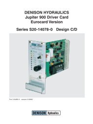
DENISON HYDRAULICS Jupiter 900 Driver Card Eurocard Version ...
DENISON HYDRAULICS Jupiter 900 Driver Card Eurocard Version ...
DENISON HYDRAULICS Jupiter 900 Driver Card Eurocard Version ...
You also want an ePaper? Increase the reach of your titles
YUMPU automatically turns print PDFs into web optimized ePapers that Google loves.
PROCEDUREINSTALLATION & OPERATIONGUIDELINES • For EMC compatibility, card must be installed in a NEMA 4 or equivalent enclosure;connect enclosure to earth ground.• Shield (screen) all wires entering enclosure. Connect card end of shield toearth ground. Leave other end of shield open.• Use Denison Hydraulics recommended power supply P/N 762-30036.• Disconnect power before inserting or removing card.• Use high resistance meter for all testpoint measurements, Ri > 100K.• Maximum wire length between driver card and pump 9A control valve is 150 feet of16 AWG, operating at minimum 22VDC supply voltage, 0.35A coil current and 80°Cfluid temperature. When using 14 AWG distance can be increased to 240 feet.SET-UP PROCEDURE1. With the hydraulic system de-energized, connect the <strong>Jupiter</strong> <strong>900</strong> driver cardaccording to the attached block diagram, then apply 24VDC to the driver card.The power LED should be illuminated and the stop LED should not be illuminated.2. If the power LED is not lit, check the wiring and apply power again.3. Connect a DVM (digital volt meter) to the I OUT test point and the GND test point onthe front panel. Apply a positive 3% command signal to the appropriate input. Adjustthe I A min potentiometer until a value of +0.124VDC (+0.124A) is read on the DVM.Apply a negative 3% command signal to the appropriate input. Adjust the IB minpotentiometer until a value of –0.124VDC (–0.124A) is read on the DVM. This isa preliminary setting.4. Apply a positive 100% command signal to the appropriate input, then adjust theIA max potentiometer to give a value of +0.30VDC (+0.30A) on the DVM. Apply anegative 100% command signal to the appropriate input, then adjust the IB maxpotentiometer to give a value of –0.30VDC (–0.30A) on the DVM. This is apreliminary setting.Note: Before energizing hydraulic system make sure that system can handle high flowrate and that max pressure limit is set to prevent system damage.5. Set the command signal to 0% and energize the hydraulic system. Slowy setcommand signal to +100% and then adjust IA MAX potentiometer for desired maxhydraulic flow. Slowly decrease command signal while observing DVM at IOUTtestpoint. Set command slightly above the IMIN trip point and then adjust IA MINpotentiometer until the minimum hydraulic output is at the desired level. Repeat theIMAX and IMIN adjustments for best hydraulic operating characteristic. Adjustmentshave slight interaction.6. For bi-directional systems repeat step 5 above with a negative command signal andadjust IB MAX and IB MIN for best operating characteristics.6


