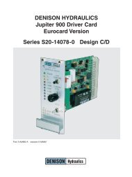
DENISON HYDRAULICS Jupiter 900 Driver Card Eurocard Version ...
DENISON HYDRAULICS Jupiter 900 Driver Card Eurocard Version ...
DENISON HYDRAULICS Jupiter 900 Driver Card Eurocard Version ...
You also want an ePaper? Increase the reach of your titles
YUMPU automatically turns print PDFs into web optimized ePapers that Google loves.
FUNCTIONAL DESCRIPTIONINPUTLocal or remote input is selected via a switch located on the front panel. In localmode a single-turn front panel command level potentiometer provides ± full-scaleinput. Local mode is recommended for system set-up process only.In remote mode several user wired input options are available. This mode is theprimary method of wiring the card for inputs from standard industrial control sourcessuch as voltage and current-loop signal generators. The user has a choice of voltage,current-loop or potentiometer when using the remote input. Voltage inputs may be ±5V,or ±10V. Current-loop inputs are differential 4-20mA 1 or ±0-20mA. DIP switches onboard are for current-loop set-up.When in remote an auxilliary ±10V input is available. This input provides theuser more input options. With all the remote input options provided, it is the user’sresponsibility to interlock multiple inputs if driver card is to be controlled by one inputat a time.1 The reverse CMD input can be used to obtain bidirectional operation.On revision level C and up, the step command pushbutton also operates when inremote mode permitting accurate ramp time settings on the remote signal that is usedin actual operation.OUTPUTPWM FREQUENCYRAMP GENERATORFRONT PANEL CONTROLSAND INDICATORSEMERGENCY STOP OPTIONThe output stage of the driver card is a two channel PWM (Pulse Width Modulated)current source with current feedback for precise control of the current through the coilregardless of the changes in coil resistance. The two outputs are protected againstshort circuits across the coil and short circuits to ground.The frequency of the PWM high current driver is factory set to 200Hz (JP2 A-B). JP2allows the frequency to be lowered to 120Hz by removing the JP2 jumper, or raised to400Hz by moving JP2 to position B-C. The 120Hz frequency setting produces moredithering effect and reduces hysteresis.Adjustable positive and negative ramping of the output is provided in two ranges of0.2-6 and 0.8-40 seconds. Ramping on-off and ramping ranges are selected by dipswitches on the card. The command level potentiometer and the step commandpushbutton located on the front panel may be used for accurate adjustments oframp times.Key indicators, potentiometer adjustments, switches and test points are brought out tothe front panel for monitoring, set-up and calibration purposes. LEDs are provided forindicating the status of the power (internal ±15VDC supplies), the coil that is energizedand the state of the emergency stop function.Potentiometer adjustments include ±ramps, I A,B min and I A,B max. Test pointsare furnished for measurement of the input, output, ramp and signal ground.A local - stop - remote switch is provided to switch control of the card from localfront panel control to user-wired remote control. Stop de-energizes emergency shutdownrelay K1, removing 24VDC from the PWM driver circuit. Jumper JP1 will allowthe card to be placed in remote mode and disable the front panel local - stop - remoteswitch, the step command push-button and the command level potentiometer. Thecommand level potentiometer is used in conjunction with the step command pushbuttonfor set-up and calibration of the driver card. Pressing then releasing the stepcommand push-button in local mode triggers the ramping of the output from zerocurrent to the current level set by the command level potentiometer, permittingaccurate and simple adjustment of both the positive and negative ramp times. Onrevision level C and up, the step command pushbutton also operates when inremote mode permitting accurate ramp time settings on the remote signal that isused in actual operation.The emergency stop (E-stop) input controls the K1 relay that provides 24VDC to theoutput driver stage. Applying logic level +15 to 24VDC to the E-stop enables the drivercard output stage. Removing the E-stop signal will abruptly halt the output current.(See soft-stop option). In revision level C and up an isolated E-stop signal option isprovided. If an isolated E-stop signal is required, remove the JP4 jumper and connectthe isolated signal common to terminal C24.4


