DENISON HYDRAULICS Jupiter 900 Driver Card Eurocard Version ...
DENISON HYDRAULICS Jupiter 900 Driver Card Eurocard Version ...
DENISON HYDRAULICS Jupiter 900 Driver Card Eurocard Version ...

Create successful ePaper yourself
Turn your PDF publications into a flip-book with our unique Google optimized e-Paper software.
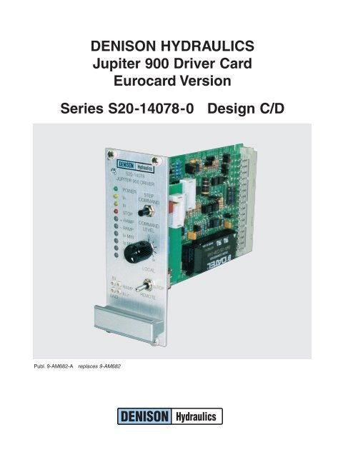
<strong>DENISON</strong> <strong>HYDRAULICS</strong><strong>Jupiter</strong> <strong>900</strong> <strong>Driver</strong> <strong>Card</strong><strong>Eurocard</strong> <strong>Version</strong>Series S20-14078-0 Design C/DPubl. 9-AM682-A replaces 9-AM682
DECLARATION OF CONFORMITYPER EMC DIRECTIVE 89/336/EEC AND EN45014MANUFACTURER’S NAMEMANUFACTURER’S ADDRESS<strong>DENISON</strong> <strong>HYDRAULICS</strong>14249 Industrial ParkwayMarysville, Ohio 43040-9504, USAdeclares that the productPRODUCT NAMEPRODUCT PART NUMBER<strong>Jupiter</strong> <strong>900</strong> <strong>Driver</strong> <strong>Card</strong>S20-14078-0conforms to the following EMC: EN50081-2: March 1994 generic emissions for heavy industry 1product specificationsEN55011: 7/1992 radiated or conducted EMI – 30-1000MHzEN50082-2: 1995 generic immunity for heavy industry 1ENV50140: 8/1993 – 10V/m, 80-1000MHz – Performance Criteria BEN61000-4-2, IEC801-2 electrostatic discharge (ESD)8KV air discharge – Performance Criteria A4KV contact discharge – Performance Criteria AEN61000-4-4: 5/1995 fast transient rejection2KV power supply wires – Performance Criteria BSUPPLEMENTARYINFORMATIONThe product was tested in an EMC TEST Laboratory in Germany and herewithcomplies with the EMC Directive 89/336 and the CE Marking requirements.1 The product was tested in a typical system configuration with <strong>DENISON</strong><strong>HYDRAULICS</strong> <strong>Jupiter</strong> Series products or recommended second source products.The tested product was mounted in a NEMA 4 enclosure (or equivalent) and all cablesexiting the enclosure were shielded (screened). Enclosure and cable shields were connectedto earth ground (PE).USA CONTACTEUROPEAN CONTACTOffice of Director of Quality<strong>DENISON</strong> <strong>HYDRAULICS</strong>14249 Industrial ParkwayMarysville, Ohio 43040<strong>DENISON</strong> <strong>HYDRAULICS</strong> Sales Officeor Office of Quality Manager<strong>DENISON</strong> <strong>HYDRAULICS</strong> GmbHGerresheimer Strasse 9D-40721 HildenDeutschlandSee Installation & Operation Guidelines under Procedures.i
PRODUCT UPDATE INFORMATIONIMPROVEMENTS AND CHANGESWORTH NOTING1. Improved power supply specification — 22-29VDC(min-max): unit will tolerateovervoltage excursions up to 40 volts.The old version specified 24-28VDC, (minimum to maximum). If the input voltageaccidentally exceeded 30 volts, including any AC peaks, the converter would fail permanently.Mobile applications with battery chargers could exceed the 30 volts; butalso fixed industrial applications with unregulated, 28VDC power supplies will readilyexceed 35 volts due to AC input tolerance and output load variations.2. Eliminated the two 1/2 amp Micro-Fuses. The new DC-DC converter has internalshort-circuit protection, eliminating the need for fuses. Total current available from±15Vdc source is 330mA, that is, onboard and off-board. Unit has over-currentprotection.3. Front panel STEP COMMAND is functional in both LOCAL and REMOTE modes.Older versions only worked in LOCAL mode.4. Added option to permit isolated power source for E-STOP function. This option isfactory set to operate as previous versions. If isolated power source is desired, movejumper JP4 from position A-B (internal GND) to B-C (isolated GND) and connect theisolated power ground to terminal C24 E-STOP RET. It made senseto provide this isolation option to the E-STOP function since the SOFT-STOP andREV CMD function can be isolated.NOTE: Terminal C24 on versions prior to REV. C was REV CMD RET. Terminal C22 isnow the REV CMD RET and SOFT-STOP RET. (We ran out of terminals).5. Added 400 Hz, as a third choice for pulse-width modulation frequency. The factoryset is 200Hz, JP2 (A-B). For 400Hz set jumper JP2 to B-C and for 120Hz removethe jumper (store the jumper on one of the pins).6. The Ramp time minimum values have increased to 0.2 and 0.8 seconds. This shouldbe of little consequence in most application. The ramp function can be shut off ifdesired.7. The IA and IB LED’s illuminate somewhat proportionately to the output current.This is a good troubleshooting tool.ii
CONTENTSPAGEEuropean EMC Directive 89/336/EECDeclaration of Conformity . . . . . . . . . . . . . . . . . . . . . . . . . . . . . . . . . . . . . . . . . iproduct update information . . . . . . . . . . . . . . . . . . . . . . . . . . . . . . . . . . . . . . . . . . . iitable of contents . . . . . . . . . . . . . . . . . . . . . . . . . . . . . . . . . . . . . . . . . . . . . . . . . . iiitechnical specifications . . . . . . . . . . . . . . . . . . . . . . . . . . . . . . . . . . . . . . . . . . . .1-2power supply requirements . . . . . . . . . . . . . . . . . . . . . . . . . . . . . . . . . . . . . . . .1reference voltages . . . . . . . . . . . . . . . . . . . . . . . . . . . . . . . . . . . . . . . . . . . . . .1remote inputs . . . . . . . . . . . . . . . . . . . . . . . . . . . . . . . . . . . . . . . . . . . . . . . . . .1operating temperature . . . . . . . . . . . . . . . . . . . . . . . . . . . . . . . . . . . . . . . . . . . .1ramp generator . . . . . . . . . . . . . . . . . . . . . . . . . . . . . . . . . . . . . . . . . . . . . . . . .1output driver . . . . . . . . . . . . . . . . . . . . . . . . . . . . . . . . . . . . . . . . . . . . . . . . . . .1feedback inputs . . . . . . . . . . . . . . . . . . . . . . . . . . . . . . . . . . . . . . . . . . . . . . . .1input command disable . . . . . . . . . . . . . . . . . . . . . . . . . . . . . . . . . . . . . . . . . . .1emergency stop input . . . . . . . . . . . . . . . . . . . . . . . . . . . . . . . . . . . . . . . . . . . .1reverse CMD input . . . . . . . . . . . . . . . . . . . . . . . . . . . . . . . . . . . . . . . . . . . . . .1soft stop input . . . . . . . . . . . . . . . . . . . . . . . . . . . . . . . . . . . . . . . . . . . . . . . . . .1LED indicators . . . . . . . . . . . . . . . . . . . . . . . . . . . . . . . . . . . . . . . . . . . . . . . . .2potentiometer adjustments . . . . . . . . . . . . . . . . . . . . . . . . . . . . . . . . . . . . . . . .2front panel local controls . . . . . . . . . . . . . . . . . . . . . . . . . . . . . . . . . . . . . . . . . .2front panel test points . . . . . . . . . . . . . . . . . . . . . . . . . . . . . . . . . . . . . . . . . . . .2mechanical . . . . . . . . . . . . . . . . . . . . . . . . . . . . . . . . . . . . . . . . . . . . . . . . . . . .2I/O connector pin assignment . . . . . . . . . . . . . . . . . . . . . . . . . . . . . . . . . . . . . .2product description . . . . . . . . . . . . . . . . . . . . . . . . . . . . . . . . . . . . . . . . . . . . . . . . .3system features . . . . . . . . . . . . . . . . . . . . . . . . . . . . . . . . . . . . . . . . . . . . . . . .3general . . . . . . . . . . . . . . . . . . . . . . . . . . . . . . . . . . . . . . . . . . . . . . . . . . . . . . .3functional description . . . . . . . . . . . . . . . . . . . . . . . . . . . . . . . . . . . . . . . . . . . . . .4-5input . . . . . . . . . . . . . . . . . . . . . . . . . . . . . . . . . . . . . . . . . . . . . . . . . . . . . . . . .4output . . . . . . . . . . . . . . . . . . . . . . . . . . . . . . . . . . . . . . . . . . . . . . . . . . . . . . . .4PWM frequency . . . . . . . . . . . . . . . . . . . . . . . . . . . . . . . . . . . . . . . . . . . . . . . .4ramp generator . . . . . . . . . . . . . . . . . . . . . . . . . . . . . . . . . . . . . . . . . . . . . . . . .4front panel controls & indicators . . . . . . . . . . . . . . . . . . . . . . . . . . . . . . . . . . . .4emergency stop option . . . . . . . . . . . . . . . . . . . . . . . . . . . . . . . . . . . . . . . . . . .4soft stop option . . . . . . . . . . . . . . . . . . . . . . . . . . . . . . . . . . . . . . . . . . . . . . . . .5reverse CMD option . . . . . . . . . . . . . . . . . . . . . . . . . . . . . . . . . . . . . . . . . . . . .5ramp-at-zero option . . . . . . . . . . . . . . . . . . . . . . . . . . . . . . . . . . . . . . . . . . . . .5closed-loop-control . . . . . . . . . . . . . . . . . . . . . . . . . . . . . . . . . . . . . . . . . . . . . .5remote operation only . . . . . . . . . . . . . . . . . . . . . . . . . . . . . . . . . . . . . . . . . . . .5procedure . . . . . . . . . . . . . . . . . . . . . . . . . . . . . . . . . . . . . . . . . . . . . . . . . . . . . . . .6installation & operation guidelines . . . . . . . . . . . . . . . . . . . . . . . . . . . . . . . . . . .6set-up procedure . . . . . . . . . . . . . . . . . . . . . . . . . . . . . . . . . . . . . . . . . . . . . . .6installation drawings . . . . . . . . . . . . . . . . . . . . . . . . . . . . . . . . . . . . . . . . . . . . . . .7-9eurocard holder outline . . . . . . . . . . . . . . . . . . . . . . . . . . . . . . . . . . . . . . . . . . .7power supply outline . . . . . . . . . . . . . . . . . . . . . . . . . . . . . . . . . . . . . . . . . . . . .8<strong>900</strong> driver card outline . . . . . . . . . . . . . . . . . . . . . . . . . . . . . . . . . . . . . . . . . . .9jumper & switch settings . . . . . . . . . . . . . . . . . . . . . . . . . . . . . . . . . . . . . . . . . .9<strong>900</strong> driver functional block diagram . . . . . . . . . . . . . . . . . . . . . . . . . . . . . . . . . . . .10input signal options diagrams . . . . . . . . . . . . . . . . . . . . . . . . . . . . . . . . . . . . . .11-12remote voltage & potentiometer . . . . . . . . . . . . . . . . . . . . . . . . . . . . . . . . . . .11current-loop with interlock . . . . . . . . . . . . . . . . . . . . . . . . . . . . . . . . . . . . . . . .12application diagrams . . . . . . . . . . . . . . . . . . . . . . . . . . . . . . . . . . . . . . . . . . . .13-19open-loop control scheme . . . . . . . . . . . . . . . . . . . . . . . . . . . . . . . . . . . . . . . .13closed-loop control scheme . . . . . . . . . . . . . . . . . . . . . . . . . . . . . . . . . . . . . . .13most common application . . . . . . . . . . . . . . . . . . . . . . . . . . . . . . . . . . . . . . . .14open-loop speed w/ hp limit . . . . . . . . . . . . . . . . . . . . . . . . . . . . . . . . . . . . . .15closed-loop speed w/ command forward . . . . . . . . . . . . . . . . . . . . . . . . . . . . .16closed-loop speed w/ com. forward & hp lmt . . . . . . . . . . . . . . . . . . . . . . . . . .17closed-loop speed w/ pi . . . . . . . . . . . . . . . . . . . . . . . . . . . . . . . . . . . . . . . . .18closed-loop speed w/ pi & hp lmt . . . . . . . . . . . . . . . . . . . . . . . . . . . . . . . . . . .19iii
TECHNICAL SPECIFICATIONSPOWER SUPPLYREQUIREMENTS22-29VDC @ 1 Amp (nominal)REFERENCE VOLTAGES Available to user +15VDC @ 250 mA (max.)–15VDC @ 250 mA (max.)+10VDC @ 0.0025 Amps max.–10VDC @ 0.0025 Amps max.REMOTE INPUTS Potentiometer 10K Ohms nominal, 5K Ohms minimumInput voltage range±5VDC, ±10VDCInput impedance100K Ohms, 200K OhmsCurrent loop input4-20mA, ±20mACurrent loop input impedance 249 OhmsAuxiliary voltage input±10VDCReverse command input+15 - +24VDCSoft stop input+15 - +24VDCOPERATING TEMPERATURERANGE0-70°CRAMP GENERATOR Switchable (DIP switch) On or OffPositive ramp (rising) range A 0.2-6 sec.Positive ramp (rising) range B 0.8-40 sec.Negative ramp (falling) range A 0.2-6 sec.Negative ramp (falling) range B 0.8-40 sec.OUTPUT DRIVERPulse width modulation (PWM) driver with current feedback and short circuit protection.PWM frequency120Hz, JP2 position no jumper200Hz, JP2 position A-B400Hz JP2 position B-CI (A,B) minimum0-460mAI (A,B) maximum w/24 Ohm load I min - 800mAFEEDBACK INPUTS Horsepower limiting command ±10VDCMajor loop±10VDCINPUT COMMAND DISABLEGnd to disableEMERGENCY STOP INPUTApply +15 to 24VDC for normal operation (optical isolation if desired).Remove 24VDC for emergency stop.Remove jumper JP4 for isolated signal source.REVERSE CMD INPUT(OPTICALLY ISOLATED)No connection for normal operation.Apply +15V to 24VDC and GND to reverse command.SOFT STOP INPUT(OPTICALLY ISOLATED)JP3 factory set to position B-C, soft stop disabled.Set JP3 to position A-B to enable soft stop.Apply 15V to 24VDC and GND for normal operation.Remove 24VDC for soft stop.1
TECHNICAL SPECIFICATIONSDESCRIPTIONLED INDICATORS Power ±15VDC supply operationalI AOutput current to coil AI BOutput current to coil BStopBoth “A” & “B” coils disabled,same as emergency stop.POTENTIOMETERADJUSTMENTS + Ramp Adjusts positive ramping time– Ramp Adjusts negative ramping timeI A MinAdjusts coil A minimum currentI B MinAdjusts coil B minimum currentI A MaxAdjusts coil A maximum currentI B MaxAdjusts coil B maximum currentFRONT PANEL LOCALCONTROLS Local-Stop-Remote switch Selects the mode of operation for the driver card.<strong>Card</strong> can be jumpered for remote operation only;set JP1 to B-C.Command level potentiometerAdjusts the input command when switched tolocal mode.Step command push-buttonForces the local remote input command to zerowhen pressed. Facilitates ramp adjustment.FRONT PANEL TEST POINTS In Input command (±10VDC)RampRamp output (±10VDC)OutCoil current scaled to ±1mV per ±1mACoil A is a positive value,Coil B is a negative valueGndSignal ground referenceMECHANICAL Dimensions, eurocard 3U, 100 x 160mm (3.9 x 6.3 in.)Dimensions, <strong>Card</strong> w/Front Panel 128.4 H x 193 D x 50.5 W mm(5 H x 7.6 D x 2 W in.)ConnectorDIN 32C, maleWeight0.22 kg (0.484 Lbs.)I/O CONNECTORPIN ASSIGNMENTS A2: +10V Ref. @ 2.5mA C2: Test Point Command InS20-14078 A4: –10V Ref. @ 2.5mA C4: Test Point Ramp First-Stage Ampl.A6: ±5V Command C6: Test Point Ramp OutA8: ±10V Command C8: Test Point Current Out Coil A/BA10: ±10V AUX Command C10: Coil A PWM OutputA12: Signal Ground C12: Coil A ReturnA14: Current-Loop In C14: Ramp-at-Zero Open-Collector UnitA16: Current-Loop Ret C16: Command InvertedA18: Major-Loop Feedback C18: Coil B PWM OutputA20: HP Limiting Command C20: Coil B ReturnA22: Soft-Stop Input C22: Soft-Stop Return / Rev. Comm. Ret.A24: Reverse Command Input C24: E-Stop ReturnA26: Signal Ground C26: Command Disable CMDDIS/A28: E-Stop Input C28: +15V @ 250mA Power OutA30: DC Power Input C30: –15V @ 100mA Power OutA32: Power Ground C32: Power Ground2
PRODUCT DESCRIPTIONSYSTEM FEATURES • Controls 9A electro hydraulic control for Gold Cup Series and premier open looppumps• Open or closed loop control (w/options card S20-11716-0)• <strong>Eurocard</strong> format (see S20-14087-0 for panel mount version)• Separately adjustable positive and negative ramps (0.2-40 sec.)• Multiple input commands• Remote potentiometer (10K CT)• ±5VDC and ±10VDC voltage inputs• +4-20mA and ±0-20mA current loop inputs• Auxiliary inputs• Soft stop option• Emergency stop option• Reverse command option• Front panel operator controls• Easy calibration• LED control indicators• Potentiometer adjustments• Special field calibration features• Special safety featuresGENERAL<strong>Jupiter</strong> driver card S20-14078-0-0 is a bidirectional pulse-width modulated current coildriver used for proportional open-loop control of the 9A electro hydraulic controlledpumps. Input commands to the card may be voltages, current loop, or potentiometer,single ended or differential. Multiple input commands are permitted but must be interlockedby the user to insure that the card is controlled by only one input at a time. Thecard also features two ranges of positive and negative ramping, remote emergencyshutdown control, options for soft stop, emergency stop and reverse command, as wellas provisions for closed-loop control with the <strong>Jupiter</strong> Options <strong>Card</strong> S20-11716. Thedriver card is packaged in a 3U eurocard size and may be operated with stand aloneDC power supplies or with the <strong>Jupiter</strong> <strong>900</strong> power supply 762-30026, which providesthe required DC power in a panel mount package.Open loop controlThe driver card with its power supply accessory is used for open-loop control.It provides multiple input commands, ramping, and front panel set-up controls.The panel mounted power supply, 762-30026, furnishes the driver card with regulatedDC power and features screw terminals for simplified panel wiring.Closed loop controlThe options card, S20-11716, is used in conjunction with the driver card for preciseclosed-loop control. It features digital and DC tachometer feedback, horsepower limiting,and PI control of feedback error. A panel mounted eurocard holder withscrew terminals is available for easy mounting. Power for the options card is obtainedfrom the driver card’s power supply.3
FUNCTIONAL DESCRIPTIONINPUTLocal or remote input is selected via a switch located on the front panel. In localmode a single-turn front panel command level potentiometer provides ± full-scaleinput. Local mode is recommended for system set-up process only.In remote mode several user wired input options are available. This mode is theprimary method of wiring the card for inputs from standard industrial control sourcessuch as voltage and current-loop signal generators. The user has a choice of voltage,current-loop or potentiometer when using the remote input. Voltage inputs may be ±5V,or ±10V. Current-loop inputs are differential 4-20mA 1 or ±0-20mA. DIP switches onboard are for current-loop set-up.When in remote an auxilliary ±10V input is available. This input provides theuser more input options. With all the remote input options provided, it is the user’sresponsibility to interlock multiple inputs if driver card is to be controlled by one inputat a time.1 The reverse CMD input can be used to obtain bidirectional operation.On revision level C and up, the step command pushbutton also operates when inremote mode permitting accurate ramp time settings on the remote signal that is usedin actual operation.OUTPUTPWM FREQUENCYRAMP GENERATORFRONT PANEL CONTROLSAND INDICATORSEMERGENCY STOP OPTIONThe output stage of the driver card is a two channel PWM (Pulse Width Modulated)current source with current feedback for precise control of the current through the coilregardless of the changes in coil resistance. The two outputs are protected againstshort circuits across the coil and short circuits to ground.The frequency of the PWM high current driver is factory set to 200Hz (JP2 A-B). JP2allows the frequency to be lowered to 120Hz by removing the JP2 jumper, or raised to400Hz by moving JP2 to position B-C. The 120Hz frequency setting produces moredithering effect and reduces hysteresis.Adjustable positive and negative ramping of the output is provided in two ranges of0.2-6 and 0.8-40 seconds. Ramping on-off and ramping ranges are selected by dipswitches on the card. The command level potentiometer and the step commandpushbutton located on the front panel may be used for accurate adjustments oframp times.Key indicators, potentiometer adjustments, switches and test points are brought out tothe front panel for monitoring, set-up and calibration purposes. LEDs are provided forindicating the status of the power (internal ±15VDC supplies), the coil that is energizedand the state of the emergency stop function.Potentiometer adjustments include ±ramps, I A,B min and I A,B max. Test pointsare furnished for measurement of the input, output, ramp and signal ground.A local - stop - remote switch is provided to switch control of the card from localfront panel control to user-wired remote control. Stop de-energizes emergency shutdownrelay K1, removing 24VDC from the PWM driver circuit. Jumper JP1 will allowthe card to be placed in remote mode and disable the front panel local - stop - remoteswitch, the step command push-button and the command level potentiometer. Thecommand level potentiometer is used in conjunction with the step command pushbuttonfor set-up and calibration of the driver card. Pressing then releasing the stepcommand push-button in local mode triggers the ramping of the output from zerocurrent to the current level set by the command level potentiometer, permittingaccurate and simple adjustment of both the positive and negative ramp times. Onrevision level C and up, the step command pushbutton also operates when inremote mode permitting accurate ramp time settings on the remote signal that isused in actual operation.The emergency stop (E-stop) input controls the K1 relay that provides 24VDC to theoutput driver stage. Applying logic level +15 to 24VDC to the E-stop enables the drivercard output stage. Removing the E-stop signal will abruptly halt the output current.(See soft-stop option). In revision level C and up an isolated E-stop signal option isprovided. If an isolated E-stop signal is required, remove the JP4 jumper and connectthe isolated signal common to terminal C24.4
FUNCTIONAL DESCRIPTIONSOFT STOP OPTIONREVERSE CMD OPTIONThe soft stop option is used to set the output current to zero at a rate set by theramp circuit. Placing JP3 in the A-B position will enable the soft stop option, positionB-C will disable the soft stop option. If the soft stop is enabled 24VDC and GNDmust be connected to the soft stop input for normal operation. Removing 24VDCfrom the soft stop input will turn off the output at a rate set by the ramp settings.Connecting 24VDC and GND across the reverse CMD input will cause the outputto switch the current from one channel to the other at a rate set by the ramp circuit.This will allow a unipolar command signal to control the pump on both sides of center.WARNING: Once the reverse CMD input has been energized loss of this signalwill reverse the driver cards output signal.RAMP-AT-ZERO OPTIONCLOSED-LOOP-CONTROLREMOTE OPERATION ONLYThe ramp-at-zero is an output that indicates when the ramp circuit output is at zero.The ramp-at-zero output is 15VDC when ramp is at zero and 0VDC when ramp is notat zero. One application for the ramp-at-zero function is to hold the integrator of the<strong>Jupiter</strong> options card, S20-11716, at zero when system command is zero.The driver card operating as a stand alone driver is used primarily for open-loop control.With the <strong>Jupiter</strong> options card, S20-11716, the driver card can be used for closed-loopspeed control systems. The options card provides digital encoder and DC tachometerfeedback, horsepower limiting and PI control of the feedback error.The front panel controls are factory enabled by JP1 at position A-B. Moving JP1 toposition B-C disables the front panel controls for remote only operation.5
PROCEDUREINSTALLATION & OPERATIONGUIDELINES • For EMC compatibility, card must be installed in a NEMA 4 or equivalent enclosure;connect enclosure to earth ground.• Shield (screen) all wires entering enclosure. Connect card end of shield toearth ground. Leave other end of shield open.• Use Denison Hydraulics recommended power supply P/N 762-30036.• Disconnect power before inserting or removing card.• Use high resistance meter for all testpoint measurements, Ri > 100K.• Maximum wire length between driver card and pump 9A control valve is 150 feet of16 AWG, operating at minimum 22VDC supply voltage, 0.35A coil current and 80°Cfluid temperature. When using 14 AWG distance can be increased to 240 feet.SET-UP PROCEDURE1. With the hydraulic system de-energized, connect the <strong>Jupiter</strong> <strong>900</strong> driver cardaccording to the attached block diagram, then apply 24VDC to the driver card.The power LED should be illuminated and the stop LED should not be illuminated.2. If the power LED is not lit, check the wiring and apply power again.3. Connect a DVM (digital volt meter) to the I OUT test point and the GND test point onthe front panel. Apply a positive 3% command signal to the appropriate input. Adjustthe I A min potentiometer until a value of +0.124VDC (+0.124A) is read on the DVM.Apply a negative 3% command signal to the appropriate input. Adjust the IB minpotentiometer until a value of –0.124VDC (–0.124A) is read on the DVM. This isa preliminary setting.4. Apply a positive 100% command signal to the appropriate input, then adjust theIA max potentiometer to give a value of +0.30VDC (+0.30A) on the DVM. Apply anegative 100% command signal to the appropriate input, then adjust the IB maxpotentiometer to give a value of –0.30VDC (–0.30A) on the DVM. This is apreliminary setting.Note: Before energizing hydraulic system make sure that system can handle high flowrate and that max pressure limit is set to prevent system damage.5. Set the command signal to 0% and energize the hydraulic system. Slowy setcommand signal to +100% and then adjust IA MAX potentiometer for desired maxhydraulic flow. Slowly decrease command signal while observing DVM at IOUTtestpoint. Set command slightly above the IMIN trip point and then adjust IA MINpotentiometer until the minimum hydraulic output is at the desired level. Repeat theIMAX and IMIN adjustments for best hydraulic operating characteristic. Adjustmentshave slight interaction.6. For bi-directional systems repeat step 5 above with a negative command signal andadjust IB MAX and IB MIN for best operating characteristics.6
INSTALLATION DRAWINGSEUROCARD HOLDER701-00007-87
INSTALLATION DRAWINGSJUMPER & SWITCH LOCATIONSCLOSEDOPEN8
POWER SUPPLY OUTLINE[mm]Input:Output:84-264VAC0.6 AMP47-440H24VDC, 1.3 AMPSDIMENSIONS IN INCHES [MILLIMETERS]9
DRIVER CARD OUTLINETOP VIEW DRIVER CARD[mm]10
<strong>900</strong> DRIVER FUNCTIONAL BLOCK DIAGRAMREVERSE CMDSOFT-STOPDIP SW1 MARKINGSO = OPEN SW1A = 1C = CLOSED SW1B = 2SW1C = 3SW1D = 4INVERTED11
INPUT SIGNAL OPTIONS85–264VAC47-440HZ12
INPUT SIGNAL OPTIONS85–264VAC47-440HZ13
14APPLICATION DIAGRAMS
APPLICATION DIAGRAMSDIP SWITCH MARKINGSO = OPEN SW1A = 1C = CLOSED (ON) SW1B = 2SW1C = 3SW1D = 4COMMAND OUT (INVERTED)15
APPLICATION DIAGRAMSCOMMAND OUT (INVERT)16
APPLICATION DIAGRAMSCOMMAND OUT (INVERT)17
APPLICATION DIAGRAMSCOMMAND OUT (INVERT)18
APPLICATION DIAGRAMSCOMMAND OUT (INVERT)19
APPLICATION DIAGRAMSCOMMAND OUT (INVERT)20
21NOTES
22NOTES
23NOTES
SALES & SERVICE WORLDWIDEInternational DistributorsIn Europe:CyprusEastern EuropeThe Faroe IslandsFinlandGreeceIcelandNorwayPortugalSwitzerlandTurkeyIn Africa:AlgeriaEgyptIvory CoastMoroccoNigeriaSouth AfricaTogoTunisiaIn Middle East:IranIsraelLebanonPakistanQatarSaudi ArabiaSyriaUnited Arab EmiratesIn Far East:IndonesiaKoreaMalaysiaNew ZealandPhilippinesThailandAustralia<strong>DENISON</strong> <strong>HYDRAULICS</strong> Pty. Ltd.41-43 St. Hillers RoadP.O. Box 192Auburn, N.S.W. 2144Tel. (612) 9646 5200Fax (612) 9643 1305Other sales offices:QueenslandSouth Wantirna VictoriaWestern AustraliaAustria<strong>DENISON</strong> HYDRAULIK GmbHZweigniederlassung LinzHaidbachstraße 69A-4061 PaschingTel. (43) 7229 4887Fax (43) 7229 63092Benelux<strong>DENISON</strong> <strong>HYDRAULICS</strong>BENELUX B. V.Pascalstraat 1003316 DordrechtHollandTel. (31) 786179 <strong>900</strong>Fax (31) 786175 755Canada<strong>DENISON</strong> <strong>HYDRAULICS</strong>CANADA Inc.2320 Bristol Circle, Unit 1Oakville, ON L6H 5S2Tel. (905) 829 5800Fax (905) 829 5805Other sales offices:Montreal, QCCalgary, ABChina, P.R.<strong>DENISON</strong> <strong>HYDRAULICS</strong> Ltd.3F, No. 1, Mao Jia Zhai, Bai Lian JingPudong New AreaShanghai 200126,Tel. (86) 21 5886 8991Fax (86) 21 5886 1978Denmark<strong>DENISON</strong> HYDRAULIKDENMARK A/SIndustrikrogen 2DK-2635 IshöjTel. (45) 4371 15 00Fax (45) 4371 15 16Finland<strong>DENISON</strong> <strong>HYDRAULICS</strong>P.O. Box 36FIN-08101 LohjaTel. (358) 208 33 045Fax (358) 207 33 045France<strong>DENISON</strong> <strong>HYDRAULICS</strong>FRANCE SA14, route du Bois BlancBP 53918105 VierzonTel. (33) 2 48 53 01 20Fax (33) 2 48 75 02 91Other sales offices:BordeauxLyonParisGermany<strong>DENISON</strong> HYDRAULIK GmbHHerderstrasse 26D-40721 HildenTel. (49) 2103 940-6Fax (49) 2103 940-880Other sales offices:DresdenHanoverStuttgartGreat Britain<strong>DENISON</strong> <strong>HYDRAULICS</strong> U.K.Ltd.Kenmore RoadWakefield 41, Industrial EstateWakefield, WF20XEWest YorkshireEnglandTel. (44) 19 24 826 021Fax (44) 19 24 826 146Other sales offices:Burgess HillHong Kong, N. T.<strong>DENISON</strong> <strong>HYDRAULICS</strong> Ltd.Unit 3, 25/F Wharf Cable Tower9 Hoi Shing RoadTsuen WanTel. (852) 24988381Fax (852) 24991522Italy<strong>DENISON</strong> <strong>HYDRAULICS</strong> S.r.l.Viale Europa 6820090 CusagoTel. (39) 2 90 33 01Fax (39) 2 90 39 06 94Japan<strong>DENISON</strong> JAPAN Inc.4-2-1 Tsujido-ShinmachiFujisawa 251,Tel. (81) 466 35 3257Fax (81) 466 35 2029Other sales office:OsakaMexico, Central America, SouthAmerica and CaribbeanCountries Contact<strong>DENISON</strong> <strong>HYDRAULICS</strong> Inc.6167 NW 181 Terrace Circle NorthMiami, FL 33015, USATel. (305) 362 2246Fax (305) 362 6220Other European, Middle Eastand African Countries Contact<strong>DENISON</strong> <strong>HYDRAULICS</strong>FRANCE SA14, route du Bois BlancBP 53918105 Vierzon CedexFranceTel. (33) 2 48 53 01 45Fax (33) 2 48 53 01 46Singapore<strong>DENISON</strong> <strong>HYDRAULICS</strong> S.E.A.Pte. Ltd.No. 11 Lorong Tukang Dua2261 SingaporeTel. (65) 2687840Fax (65) 2687847Spain<strong>DENISON</strong> <strong>HYDRAULICS</strong>, S.A.Gomis, 108023 BarcelonaTel. (34) 3418 46 87Fax (34) 3211 65 07Other sales offices:San SebastianSweden<strong>DENISON</strong> <strong>HYDRAULICS</strong>SVENSKA ABSporregatan 13213 77 - MalmöTel. (46) 40 21 04 40Fax (46) 40 21 47 26Other sales offices:SpångaTaiwan, R.O.C.<strong>DENISON</strong> <strong>HYDRAULICS</strong> Ltd.6F-10, No. 79, Sec. 2, Roosevelt RoadTaipei,Tel. (886) 2 3645101 / 3645102Fax (886) 2 3639025USA<strong>DENISON</strong> <strong>HYDRAULICS</strong> Inc.14249 Industrial ParkwayMarysville, OH 43040Tel. 937 644 3915Fax 937 642 3738For nearest Distributor:Call toll free 1 800 551 5956Other sales offices:Fulton, CAMulberry, FLMoline, ILRock Island, ILKentwood, MIPortland, ORCollierville, TNArlington, TXHouston, TXYour local <strong>DENISON</strong> representativePrinted in U.S.A. 7/98Internet: http://www.denisonhydraulics.comE-mail: denison@denisonhydraulics.com