DENISON HYDRAULICS Jupiter 900 Driver Card Eurocard Version ...
DENISON HYDRAULICS Jupiter 900 Driver Card Eurocard Version ...
DENISON HYDRAULICS Jupiter 900 Driver Card Eurocard Version ...

Create successful ePaper yourself
Turn your PDF publications into a flip-book with our unique Google optimized e-Paper software.
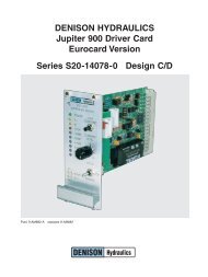
TECHNICAL SPECIFICATIONSDESCRIPTIONLED INDICATORS Power ±15VDC supply operationalI AOutput current to coil AI BOutput current to coil BStopBoth “A” & “B” coils disabled,same as emergency stop.POTENTIOMETERADJUSTMENTS + Ramp Adjusts positive ramping time– Ramp Adjusts negative ramping timeI A MinAdjusts coil A minimum currentI B MinAdjusts coil B minimum currentI A MaxAdjusts coil A maximum currentI B MaxAdjusts coil B maximum currentFRONT PANEL LOCALCONTROLS Local-Stop-Remote switch Selects the mode of operation for the driver card.<strong>Card</strong> can be jumpered for remote operation only;set JP1 to B-C.Command level potentiometerAdjusts the input command when switched tolocal mode.Step command push-buttonForces the local remote input command to zerowhen pressed. Facilitates ramp adjustment.FRONT PANEL TEST POINTS In Input command (±10VDC)RampRamp output (±10VDC)OutCoil current scaled to ±1mV per ±1mACoil A is a positive value,Coil B is a negative valueGndSignal ground referenceMECHANICAL Dimensions, eurocard 3U, 100 x 160mm (3.9 x 6.3 in.)Dimensions, <strong>Card</strong> w/Front Panel 128.4 H x 193 D x 50.5 W mm(5 H x 7.6 D x 2 W in.)ConnectorDIN 32C, maleWeight0.22 kg (0.484 Lbs.)I/O CONNECTORPIN ASSIGNMENTS A2: +10V Ref. @ 2.5mA C2: Test Point Command InS20-14078 A4: –10V Ref. @ 2.5mA C4: Test Point Ramp First-Stage Ampl.A6: ±5V Command C6: Test Point Ramp OutA8: ±10V Command C8: Test Point Current Out Coil A/BA10: ±10V AUX Command C10: Coil A PWM OutputA12: Signal Ground C12: Coil A ReturnA14: Current-Loop In C14: Ramp-at-Zero Open-Collector UnitA16: Current-Loop Ret C16: Command InvertedA18: Major-Loop Feedback C18: Coil B PWM OutputA20: HP Limiting Command C20: Coil B ReturnA22: Soft-Stop Input C22: Soft-Stop Return / Rev. Comm. Ret.A24: Reverse Command Input C24: E-Stop ReturnA26: Signal Ground C26: Command Disable CMDDIS/A28: E-Stop Input C28: +15V @ 250mA Power OutA30: DC Power Input C30: –15V @ 100mA Power OutA32: Power Ground C32: Power Ground2