Installation Instructions – RVR Solar Water Heating Kits - RVR.ie
Installation Instructions – RVR Solar Water Heating Kits - RVR.ie
Installation Instructions – RVR Solar Water Heating Kits - RVR.ie

Create successful ePaper yourself
Turn your PDF publications into a flip-book with our unique Google optimized e-Paper software.
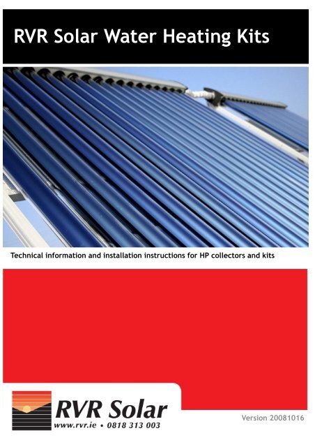
<strong>Installation</strong> <strong>Instructions</strong><strong>RVR</strong> <strong>Solar</strong> <strong>Water</strong> <strong>Heating</strong> <strong>Kits</strong>Technical information and installation instructions for HP collectors and kits1Version 20081016
<strong>RVR</strong> <strong>Solar</strong> <strong>Water</strong> <strong>Heating</strong> <strong>Kits</strong>Table of ContentsPage Title3 System Schematics and Circuits4 Equipment Specifications4 <strong>Solar</strong> water heating kits6 Important pre installation considerations7 <strong>Installation</strong>7 1. Mounting the collectors on the roof or other location7 1.1 Unpacking the collectors8 1.2 Mounting the collectors on a sloped roof9 1.2.1 Hangar Bolt Location and mounting9 1.2.2 Mount the slotted tabs10 1.2.3 Fit bracket cross members10 1.2.4 Fit the Frame10 1.2.5 Fit the Heat Pipes11 2. Piping using <strong>RVR</strong> <strong>Solar</strong>flex11 2.1 System Layout11 2.2 Pipe sizing12 2.2 Connection of <strong>RVR</strong> <strong>Solar</strong>flex13 2.3 Roof penetrations and pipe flashings14 3. <strong>Installation</strong> of the Twin Coil tank.15 4. <strong>Installation</strong> of the <strong>Solar</strong> Station and expansion vessel15 4.1 Mounting the solar station16 4.2 Piping the <strong>Solar</strong> Station and mounting the expansion vessel:17 5. Flushing, Filling And Leak Testing2
<strong>Installation</strong> <strong>Instructions</strong>System Schematics and CircuitsDetailed information on the design of solar systems is available in the <strong>RVR</strong> publication, <strong>Solar</strong> System DesignGuide. This may be downloaded from www.<strong>RVR</strong>.<strong>ie</strong> and should be read carefully before designing a system.The most common type of solar water heating system is a system which uses a twin coil water heater. A schematicfor this type of system is shown below.This type of system is suited to both new and retro-fit installations where the water heater is to be replaced. Atwin coil water heater is used as a thermal store, with the solar circuit connected to the lower coil. The tankused should be tall and narrow to ensure good stratification of the heated water. A boiler is usually connectedto the upper coil. In this type of system the solar system will be able to provide a large percentage of the domestichot water needs of the household. Systems are usually designed to provide about 60% of the annualamount of hot water needed.The most important components of a typical system are listed below:1. <strong>Solar</strong> Panels2. <strong>Solar</strong> Station3. Twin Coil <strong>Water</strong> Heater4. Mixing valve5. Expansion Vessel6. <strong>Solar</strong> FluidFig. 1 - Typical solar water heating system3
<strong>RVR</strong> <strong>Solar</strong> <strong>Water</strong> <strong>Heating</strong> <strong>Kits</strong>Equipment Specifications<strong>RVR</strong> <strong>Solar</strong> HP models are vacuum tube collectors, which use a heat pipe for energy transfer from the absorberto the solar fluid. These operate with high-effic<strong>ie</strong>ncy in all solar radiation conditions. The vacuum containedbetween the glass tubes provides excellent insulation, which enhances the overall effic<strong>ie</strong>ncy of the collector.Operating parametersMaximum fluid pressure:10 barMaximum Operating fluid pressure: 6 barMaximum service temperature: 95°CMaximum stagnation temperature: 200.3 °CRecommended tilt angle: 15° - 75°Fluid Flow range recommendation: 0.5 -1.5 l/m 2 minOptical Effic<strong>ie</strong>ncy (η 0 ) 0.734Linear Loss Co-effic<strong>ie</strong>nt (a1) 1.529 W/m 2 KQuadratic Loss Co-effic<strong>ie</strong>nt (a2) 0.0166 W/m 2 K 2Fig. 2 - Collector DimensionsApertureModel Dimensions area (m 2 ) Empty Fluid Full Connection Collector Sloped roof(A x B x C) (mm)weight Content weight Size (mm) Stock bracket kit(kg) (litres) (kg)No. Stock no.HP20 2020 ×1825 ×155 1.861 78 1.8 80 22 SOL401 ASB120HP30 2020 ×2655 ×155 2.791 115 2.3 118 22 SOL402 ASB130<strong>Solar</strong> water heating kitsA range of standard solar water heating kits are available from <strong>RVR</strong>. All of these kits contain matched componentswhich optimise the performance of the system.<strong>RVR</strong> <strong>Solar</strong>—HP <strong>Solar</strong> <strong>Water</strong> <strong>Heating</strong> <strong>Kits</strong>There are two types of pre-packaged kits available from <strong>RVR</strong>:<strong>Kits</strong> without water heating tankThese kits contain collectors, <strong>Solar</strong> Station, <strong>Solar</strong> Expansion Vessel and <strong>Solar</strong> fluid. Thesekits are suited to applications where a suitable water heater is already installed.Fig. 3<strong>Kits</strong> with water heating tankThese kits contain collectors, <strong>Solar</strong> Station, <strong>Solar</strong> Expansion Vessel , <strong>Solar</strong> fluid, Twin coiltank and mixing valve. These kits are suited to applications where a full solar water heatingsystem is being installed.Fig. 44
<strong>Installation</strong> <strong>Instructions</strong><strong>Kits</strong> without water heating tank <strong>–</strong> suitable for applications where a tank is already installedKit Stock NoCollectorsNo ofTubes Gross Area Aperture AreaExpansionVessel<strong>Solar</strong> Fluid<strong>Solar</strong> Station<strong>Water</strong> BlendingValveTwin CoilTankSizem2 m2 litres litres litresASK700 1 x HP20 20 2.62 1.861 19 20L<strong>RVR</strong>Prostation - -ASK710 1x HP30 30 3.93 2.791 19 20L<strong>RVR</strong>Prostation - -ASK720 2 x HP20 40 5.24 3.722 19 30L<strong>RVR</strong>Prostation - -ASK7301 x HP20 and 1 x<strong>RVR</strong>HP30 50 6.55 4.652 19 30L Prostation - -<strong>RVR</strong>ASK740 2 x HP30 60 7.86 5.582 19 30L Prostation - -ASK750 3 x HP30 90 11.79 8.373 40 40L Flocon S - -ASK760 4 x HP30 120 15.72 11.164 40 50L Flocon S - -ASK770 5 x HP30 150 19.65 13.955 40 60L Flocon S - -<strong>Kits</strong> with water heating tankKit Stock NoCollectorsNo ofTubes Gross Area Aperture AreaExpansionVessel<strong>Solar</strong> Fluid<strong>Solar</strong> Station<strong>Water</strong> BlendingValveTwin CoilTank Sizem 2 m 2 litres litres litresASK600 1 x HP20 20 2.62 1.861 19 20L<strong>RVR</strong>Prostation 1.6 KVS, 3/4" 200ASK610 1x HP30 30 3.93 2.791 19 20L<strong>RVR</strong>Prostation 1.6 KVS, 3/4" 200ASK620 2 x HP20 40 5.24 3.722 19 30L<strong>RVR</strong>Prostation 1.6 KVS, 3/4" 270ASK6301 x HP20 and 1 x<strong>RVR</strong>HP30 50 6.55 4.652 19 30L Prostation 1.6 KVS, 3/4" 300<strong>RVR</strong>ASK640 2 x HP30 60 7.86 5.582 19 30L Prostation 1.6 KVS, 3/4" 300ASK650 3 x HP30 90 11.79 8.373 40 40L Flocon S 3.0 KVS, 1" 500ASK660 4 x HP30 120 15.72 11.164 40 50L Flocon S 10.0 KVS, 11/4" 800ASK670 5 x HP30 150 19.65 13.955 40 60L Flocon S 10.0 KVS, 11/4" 1000Please Note:The <strong>Kits</strong> above are basic kits and do not include piping, brackets or roof flashing. Please see www.rvr.<strong>ie</strong> for informationon the latest kits and offers available.5
<strong>RVR</strong> <strong>Solar</strong> <strong>Water</strong> <strong>Heating</strong> <strong>Kits</strong>Important pre-installation considerationsOr<strong>ie</strong>ntationThe collectors should be or<strong>ie</strong>nted to face South where possible.However a variation of up to 15° from South does nothave a significant effect on effic<strong>ie</strong>ncy. Or<strong>ie</strong>ntation between SEand SW will typically affect effic<strong>ie</strong>ncy by less than 5%.By compensating with more collector area, it is possible to or<strong>ie</strong>nt the collectors anywhere between east andwest as the loss of effic<strong>ie</strong>ncy at these extreme or<strong>ie</strong>ntations is approximately 25%.Tilt angleThe tilt angle at which you mount the collector should roughly correspond to the latitude of the location. Theoptimum tilt angle is about 50° for installations in Ireland or the UK although any angle between 30° and 60°will give good results.Angles greater than 60° result in a significant loss of effic<strong>ie</strong>ncy in summer. The loss of effic<strong>ie</strong>ncy at a tilt angleof 80° will be about 20%. This may be compensated for by installing additional collector area.ShadeTry to avoid significant shading of more than 2 hours per spring or autumnday.Ideally, the distance from an obstacle to the East, South or Westshould be at least 2.5 times the height of the obstacle.Fig. 5Distance from solar storeFig. 6The collectors should be as close to the tank as possible in order to minimise heat and pressure loss. The distancebetween collectors and tank should ideally be less than 20m for domestic applications.Access for installation and maintenanceThe area where the collectors are installed should have easy and safe access for maintenance and installation.Piping and collector layoutWhen planning the location of the collectors, it is important to bear in mind that no more than 90 tubes can belocated in ser<strong>ie</strong>s (e.g. 3 x HP30 panels or 4 x HP20 panels). This is covered in more detail on page 11 of thisdocument.Do not insert tubes until commissioningIf the system is to be installed but not commissioned until later then the tubes should not be mounted in thecollector frame until commissioning to prevent damage from overheating.6
<strong>Installation</strong> <strong>Instructions</strong><strong>Installation</strong>Standards and CodesThe installation of the solar system should only be carr<strong>ie</strong>d out by suitably qualif<strong>ie</strong>d and certif<strong>ie</strong>d personnel.All applicable standards and codes of practice should be compl<strong>ie</strong>d with. These include but are not limited to :• Safety, Health and Welfare at Work Act 2005• Any requirements of the Health and Safety Authority• The Building Regulations• Local Authority Requirements• EN 12975 and EN 12976 which deal with <strong>Solar</strong> Systems and Collectors• lEE Regulations• Any applicable regulations or codes of practice relevant to installation of unvented water heaters• Any other applicable local national or European codes or standardsThe installation of the system has several stages:1. Mounting the collectors on the roof or other location2. Piping the system using <strong>RVR</strong> solarflex3. <strong>Installation</strong> of the twin coil tank4. <strong>Installation</strong> of the solar station and expansion vessel5. Testing and filling the system6. Commissioning the system1. Mounting the collectors on the roof or other location1.1 Unpacking the collectorsThe HP solar collectors are delivered as a complete kit in boxes. There are four boxes for each HP20 collectorand five boxes for each HP30 collector.Figure 7 shows one box which contains the ‘Manifold and BottomSupport’ and another box which contains the ‘Frame’. Theboxes are clearly marked. There is one of each box type foreach collector.Fig. 7Figure 8 shows the boxes which contain the tubes. There are10 tubes in each box. There are two tube boxes for a HP20 collectorand three tube boxes for a HP30 collector.Fig. 8The boxes containing the tubes will not be needed until later.The contents of the unpacked Manifold and Bottom Support’and ‘Frame’ boxes are shown in Figure 9.Fig. 9Before proceeding, insert therubber sealing rings into theheader, as shown in fig. 10Fig. 107
<strong>RVR</strong> <strong>Solar</strong> <strong>Water</strong> <strong>Heating</strong> <strong>Kits</strong>1.2 Mounting the collectors on a sloped roofBefore starting any work:Ensure that all risks are minimised by implementing safe access methods and following best practice for workingat heights above the ground.Check with a qualif<strong>ie</strong>d person that the roof is strong enough to support the additional weight and wind loading.The collectors are mounted using specially designed roof brackets. These brackets have been designed specificallyfor Irish roof systems and the harsh Irish weather. They are professionally manufactured from highquality stainless steel. They will have an almost unlimited life in all normal environments. When installing solarpanels in areas exposed to salt water spray or in heavily polluted atmospheric conditions, some corrosion maybe exper<strong>ie</strong>nced. If this is not acceptable, please contact <strong>RVR</strong> for technical advice prior to installation.An installed roof bracket with manifold bottom support andframe is shown in figure 11.Do not mount the collector too close to the roof edge so as toavoid wind turbulence effects. Ideally the collector shouldbe at least 500mm from the roof edge.Fig. 11All roof kits are mounted using hanger bolts as shown in Figure12.This type of fastener has a wood screw at one end and athreaded machine screw at the other end. It is important topilot drill the holes for the hangar bolts before attempting toscrew them into the roof.Fig. 12First determine the approximate location of the roof bracket.If the inside of the roof can be accessed, then go into the atticand mark the location of the lower mounting holes for thebracket.Now drill out through the rafter and slate with a long 6mmmasonry bit making sure that the drill is perpendicular to therafter. See figure 13.Fig. 138
<strong>Installation</strong> <strong>Instructions</strong>1.2.1 Hangar Bolt Location and mountingFigure 14 shows the mounting of a HP30 and HP20 bracket in relation to the roof rafters. The rafters typicallyare spaced on 400mm centres. In this case the horizontal spacing of the hangar bolts for the HP30 brackets isabout 1600mm apart (4 rafter spaces). The space for the HP30 is about 1200mm or three rafter spaces.The vertical distance between hangarbolts is 1250 - 1300 mm.The cross-members are slotted toallow horizontal adjustment. If it isintended to connect two or more collectorsin ser<strong>ie</strong>s the installed distancebetween each bracket should be approximately125mm.Once satisfactory locations havebeen measured and marked the drillingmay be completed.Fig. 14Fig. 15When all pilot holes have been drilled—drill 11mm clearance holes from the outside.Next lock two SS nuts together as shownand twist in the hanger bolt until 50mm ofthreaded bolt protrudes above the roofsurface.Apply some of the special purpose sealant(suppl<strong>ie</strong>d) to the surface around thebolt. Fit the 5mm thick neoprene washerfollowed by the 40mm SS washer and SSnut. Tighten the nut by hand until youcannot turn it any more and then give itone full turn to form a watertight seal.Do not over tighten or you may breakthe slate or roof tile!Fig. 16We recommend the application of some more adhesive sealant aroundthe washer to give extra protection against the weather. Screw anotherSS nut on the protruding bolt and leave a small space between the firstand second nut.1.2.2 Mount the slotted tabsUse a further nut to fasten the slotted stainless steel tab onto thehanger bolt.Figure 17 illustrates how the bracket should be assembled with thelower cross-member fitted.Fig. 179
<strong>RVR</strong> <strong>Solar</strong> <strong>Water</strong> <strong>Heating</strong> <strong>Kits</strong>1.2.3 Fit bracket cross membersThe bracket cross members may now be fittedto the slotted stainless steel tab using the M10 x20mm screws, washers and nylock nuts provided.The cross member with the tabs is intendedto support the lower cross member ofthe collector while the cross member withoutthe tabs is located close to the top of the collector.The tabs prevent the solar collector framefrom slipping while it is clamped down to thecross member.The tabs hold the solarcollector frame from slippingoff the bracketwhilst it is being clamped Fig. 181.2.4 Fit the FrameThe collector frame is fastened into position using the metal clamps and M8 x 40mm screws and nuts as shownin fig 19.The screws have a square shoulder. This provides a locking mechanism which prevents rotation whilst tighteningthe nuts.1.2.5 Fit the Heat PipesFig. 19If it is intended to commission the system immediately then the heat-pipes can now be installed into theheader. Otherwise do not do this until just before the system is placed in service. Premature installationof the heat pipes may lead to their degradation.Wet the chrome-plated bulb and the top of the glass tube with water. This helps the heat-pipe to slide easilyinto the header. Screw on the retaining cups (fig. 22) as you are fitting the heat-pipes.Fig. 20 10Fig. 21 Fig. 22
<strong>Installation</strong> <strong>Instructions</strong>2. Piping using <strong>RVR</strong> <strong>Solar</strong>flex2.1 System LayoutThe system should be piped with the <strong>RVR</strong> <strong>Solar</strong>flex piping system. This is a flexible, pre-insulated pipe systemspecially designed for solar thermal systems. Fittings kits are available from <strong>RVR</strong> which include all fittingsneeded for piping using <strong>RVR</strong> <strong>Solar</strong>flex.LimitationsThe distance between the collectors and the water heating tank should be kept as short as possible. (ideallynot more than 20m for domestic installations)No more than 90 tubes (3 x HP30 collectors or 4 x HP20 collectors)should be connected in ser<strong>ie</strong>s.Where larger numbers of collectors are installed they shouldbe piped in parallel with balanced connections as shown in figure24.Fig. 23—Max 90 tubes in ser<strong>ie</strong>sFig. 24—Balanced Piping Design2.2 Pipe Sizing<strong>RVR</strong> <strong>Solar</strong>flex piping is available in three sizes DN16, DN20 and DN25. Measure the distance between the collectorsand water heater. Consult the table below for pipe sizes.Fig. 25Fig. 26—<strong>RVR</strong> <strong>Solar</strong>flexNo ofTubesDistance (m)10 15 20 25 3060 DN16 DN16 DN16 DN16 DN16120 DN16 DN16 DN20 DN20 DN20180 DN20 DN20 DN20 DN20 DN20240 DN20 DN20 DN20 DN25 DN25300 DN25 DN25 DN25 DN25 DN2511
<strong>RVR</strong> <strong>Solar</strong> <strong>Water</strong> <strong>Heating</strong> <strong>Kits</strong>2.2 Connection of <strong>RVR</strong> <strong>Solar</strong>flexPipe which is installed externally should be protected againstultra-violet radiation and also protected from rain and snow.The pipe which is immediately connected to the collectors canalso become very hot in certain conditions.For these reasons, the final connection to the solar collectorsshould be made using the special <strong>RVR</strong> Twin <strong>Solar</strong>flex Externaltails.These are insulated with Armaflex HT insulation and enclosed ina UV and weather resistant coating. The pack (<strong>RVR</strong> Stock No.ASK180) contains 2 x 1m long DN16 (3/4" BSP) tails, with backnuts and nipples at one end, and back nuts at the other. Thismakes them suitable for joining directly to piping internally andconnection to an elbow on a collector or other fitting externally.All internal piping can then be completed using Twin <strong>Solar</strong>FlexInternal Preinsulated Piping which is available in DN16, DN20and DN25 sizes and lengths of up to 20m.Fig. 27 - <strong>RVR</strong> <strong>Solar</strong>flex External TailsPipe Joining:Fig. 28Fig. 291. Cut the pipe with a tube cutter as shown.(Warning: Take care!!—the pipe end can be very sharp!)2. Put the backnut on the pipe, then place the segment ring in the first grooveback from the end and squeeze it tightly around the pipe.3. Tighten the connection using the threaded nipple and nut to create a flat endon the pipe.4. Finally insert the fibre washer to create a leak proof seal. Do not use any typeof lubricant or sealant.12
<strong>Installation</strong> <strong>Instructions</strong>2.3 Roof penetrations and pipe flashingsWeatherproof roof penetrations may be easily made using <strong>RVR</strong> <strong>Solar</strong>flex flashings. Flashings are available forslate/flat tile roofs and for corrugated tile roofs.Fig. 30—Flashing for slate and flat tilesFig. 31—Flashing for corrugated tilesPilot drill a hole at a suitablelocation on the roof.Use a hole saw to drill a holeof the correct diameter.Coat the slate or tilewith mastic.Trim the flashing to thecorrect size..Fig. 32—Installing Slate flashingSlide the flashing under theoverlapping slates or tiles andfix using pins...Flashings are installed on corrugated tiles in a similar fashion. The base of this type offlashing is flexible and may be moulded to fit the shape of the roof tiles.Fig. 33—Installing corrugated tile flashing13
<strong>RVR</strong> <strong>Solar</strong> <strong>Water</strong> <strong>Heating</strong> <strong>Kits</strong>3. <strong>Installation</strong> of the Twin Coil <strong>Water</strong> Heater.The Twin Coil <strong>Water</strong> heater (sometimes called the thermal store) must be installed by a qualif<strong>ie</strong>d plumber.Its’ correct installation is critical to the safety of the system.All relevant standards and codes of practice for the installation and commissioning of both open and unventedwater heating systems should be adhered to.Separate instructions are available for the <strong>RVR</strong> Twin Coil <strong>Water</strong> Heater. Please read this manual thoroughlybefore installing the water heater.Specifications<strong>RVR</strong> 200L <strong>RVR</strong> 250L <strong>RVR</strong> 300LNominal Capacity Litres 200 250 300Max. DHW Pressure bar 10 10 10Max. Primary Pressure bar 6 6 6Max. Operating Temperature °C 90 90 90Standing Heat Loss kWh/24h 1.21 1.48 1.74Dedicated <strong>Solar</strong> Volume Litres 122 155 178Upper Coil information:Upper Coil Performance kW 14.1 15.2 18.6Upper Coil <strong>Water</strong> Content Litres 4.5 5.4 6.3Upper Coil Pressure Drop kpa 19.5 25.4 28.2Upper Coil Flow Rate Litres/s 0.17 0.18 0.22Reheat Time minutes 15 18 18Lower Coil information:Lower Coil Performance kW 16.5 18.5 20.8Upper Coil <strong>Water</strong> Content Litres 5.7 6.65 7.6Lower Coil Pressure Drop kpa 32.0 34.0 39.3Lower Coil Flow Rate Litres/s 0.20 0.22 0.25Reheat Time minutes 23 29 32Fig. 34—Twin Coil <strong>Water</strong> HeaterDimensions200L 250L 300LA mm 1480 1835 2170B mm 520 520 520C mm 320 320 320D mm 180 180 200E mm 260 270 290F mm 390 400 492G mm 825 1000 1147H mm 1138 1417 1682I mm 1220 1555 1867J mm 1300 1655 1970Dry Weight kg 57 66 72Full Weight kg 257 316 37214Fig. 34
<strong>Installation</strong> <strong>Instructions</strong>4. <strong>Installation</strong> of the <strong>Solar</strong> Station and expansion vessel4.1 Mounting the solar stationThe <strong>Solar</strong> station contains the system controller, pump, safety valve, flow meter, service valves, expansionvalve connection and connections for filling and topping up the system.• Select a suitable position for mounting the solar station.• Unpack the solar station and remove the front insulation jacket.• Let the solar station screwed to the back part of the insulation jacket.• Mark the mounting hole positions through the insulation and drill with an 8 mm drill. Insert plugs into theholes.• Mount the solar station with the screws provided.• Mount and connect the expansion vessel• Connect flow and return piping to the collectors and water heating tank (thermal store).The solar station will often be mounted in a cupboard or location which the user may find difficult to access.In these situations, the controller may be removed from the solar station and mounted remotely in a locationwhich is more accessible to the user. Please consult the <strong>Solar</strong> station manual for wiring instructions.There are two models of solar station used in the <strong>RVR</strong> <strong>Solar</strong> <strong>Water</strong> heating kits. These are the <strong>RVR</strong> Prostationmodel and the Flocon S model. These are shown in figure 35.Fig. 3515
<strong>RVR</strong> <strong>Solar</strong> <strong>Water</strong> <strong>Heating</strong> <strong>Kits</strong>4.2 Piping the <strong>Solar</strong> Station and mounting the expansion vessel:The following pipe connections are required to the solar station.1. <strong>Solar</strong> piping to the collectors and lower coil of the water heating tank.2. Connection of the safety valve to a drain: This should be done in metal pipe and the discharge pointshould be visible so that any leaks are noticeable by the user.3. Connection of the expansion vessel: A flexible pipe, clutch valve, mounting bracket are suppl<strong>ie</strong>d in the kitwith each expansion vessel. The flexible hose should be connected to the Expansion vessel connectionpoint. The expansion vessel should then be mounted as shown in figure 34.Note: The clutch valve is a conven<strong>ie</strong>nt component as it allows disconnection of the expansion vessel after thesystem has been pressurised without the necessity of draining down the system.The importance of the expansion vesselThe expansion vessel is an essential system component.European Standard EN 12976 requires that solar heating systems are safe and do not require any specialmeasures on the part of the user when exposed to prolonged high levels of solar radiation without heat consumption.The worst case situation will occur when the electrical supply is interrupted or the system circulation pumpfails. In this case, the fluid contained in the collectors may vapourise displacing it’s own volume. The functionof the expansion vessel is to provide a reservoir for the displaced fluid and prevent the system pressurerising to the point at which the safety valve opens (6 bar).An expansion vessel of suffic<strong>ie</strong>nt size is required to contain the displaced collector fluid. A correctly sizedexpansion vessel is included in each <strong>RVR</strong> kit. Please see the specification tables in this manual for sizes.Expansion vessel pressureCheck the expansion vessel pressure using a suitable gauge before installing it. The correct pressure is 2bar. Increase or decrease pressure as required.16Fig. 34 - <strong>Solar</strong> Station Piping
<strong>Installation</strong> <strong>Instructions</strong>5. Flushing, Filling And Leak Testing<strong>Solar</strong> FluidThe lowest recorded temperature in Ireland is almost -20°C. The solar fluid suppl<strong>ie</strong>d in the <strong>RVR</strong> <strong>Solar</strong> <strong>Water</strong>heating kit has a freezing point of -28°C.Do not dilute the solar fluid. This will change it’s freezing point and viscosity.Do not use any other type of solar fluid in the system.Filling and flushing the solar circuitApply an air pressure test to the system to check for leaks. Once it is clear that there are no leaks in the system,proceed as follows:Filling the system withpump stationFig. 35<strong>RVR</strong> Prostation with labellingof parts used for commissioningFlocon S solar station withlabelling of parts used for commissioning• Use an <strong>RVR</strong> 8 bar solar filling pump station to purge and fill the system.• Connect the filling pump supply hose to the filling valve and open the valve.• Connect filling pump drain hose to the drain valve and open the valve.• Close the commissioning ball valve on the solar station.• Add suffic<strong>ie</strong>nt solar fluid for the system into the reservoir of the filling pump station. Start the pumpand flush the solar circuit for at least 15 minutes. To get the air completely out of the system, open thecommissioning valve after five minutes and then close it again.• Do not use water to flush the system as it may present a danger of frost damage if it is not completelypurged.• Close the Drain Valve while the filling pump is running and increase the system pressure to about 3 bar.The system pressure is displayed by the manometer.• Close the Filling Valve and switch-off the pump. Open the Commissioning Valve.Set the System PressureThe system pressure must be set to 2.2 bar for correct operation. Drain some fluid via the drain valve to17
<strong>RVR</strong> <strong>Solar</strong> <strong>Water</strong> <strong>Heating</strong> <strong>Kits</strong>Set the System FlowrateStart the circulation pump in manual mode (see <strong>Solar</strong> station/controller instructions) at its maximum pumpspeed setting. It may be necessary to bleed the circulating pump by unscrewing the brass screw on the pumpface. Replace the brass screw one the pump has vented.Once satisfactory circulation is obtained,the system flow rate needs to be set tobetween 0.5 and 1.5 Litres/minute foreach m 2 of collector aperture area in thesystem.. In practice the following valuesare recommended:Kit Stock No Collectors No of Tubes FlowrateL/minASK700 /ASK600 1 x HP20 20 1.5ASK710 /ASK610 1x HP30 30 2.0ASK720 /ASK620 2 x HP20 40 2.5ASK730 /ASK630 1 x HP20 and 1 x HP30 50 3.0ASK740 /ASK640 2 x HP30 60 3.5ASK750 /ASK650 3 x HP30 90 5.0ASK760 /ASK660 4 x HP30 120 7.0ASK770 /ASK670 5 x HP30 150 9.0Adjust the flow rate as follows:• Reduce the pump speed to the lowest speed which permits the required flow rate to be obtained.Adjust the flow regulating valve to get the correct flowrate.• Disconnect the hoses from the filling and drain valves and screw the caps onto the valves.• Recheck the system once again for leaks.• Open the ball valve above the pump completely.• Mount the front insulation jacket to the solar station.• The system is now ready for use.• Refer to the controller/solar station instructions for further system settings.Electrical WiringThe following are the wiring requirements for the solar system:• The <strong>Solar</strong> Station requires a 220V, 50 Hz power supply. Fused at 5 amps.• A temperature sensor should be fitted near to the bottom of the water heater. This should be wired tothe correct connection point on the solar station via a 2 core cable.• A temperature sensor should be fitted to the outlet of the collector. This should be wired to the correctconnection on the solar station via a 2 core cable. Please see diagram below.• When the solar station is used to control the supplementary heat source, a second sensor will need tobe fitted to the upper third of the thermal store. This should be wired to the correct connection on thesolar station via a 2 core cable. Please seediagram below.For detailed wiring information, please refer to thesolar station/controller instruction booklet.18Fig. 36
<strong>Installation</strong> <strong>Instructions</strong><strong>Installation</strong> points to be checkedThe following points should be checked to ensure a safe and properly functioning solar water heating system.1. <strong>Installation</strong> of collectorsa) Collectors have been fastened to the roof to support collector weight and wind\snow loadsb) Collectors are properly or<strong>ie</strong>nted (between South-East and South-West)c) Potential for shading of collectors (trees, buildings, etc.) is limitedd) <strong>Water</strong>proofing and air sealing of collector-to-roof connections and pipe penetrations2. <strong>Solar</strong> Loopa) <strong>Solar</strong> loop pipe work is watertight\airtight under pressure)b) Pipe work in the solar loop has been insulated thoroughly (no significant gaps in slits or clips or jointsc) <strong>Solar</strong> loop insulation material to withstand collector stagnation temperaturesd) <strong>Solar</strong> loop external pipe and fittings insulated with UV resistant insulatione) Pipe penetrations of building fabric made good, debris removed from sitef) Pipes securely fixed but allowing for thermal movementg) Expansion and pressure release valve sized and installed correctlyh) Connection of solar loop to storage tank heat exchanger is correcti) Collection of anti freeze liquid from pressure rel<strong>ie</strong>ve valve in placej) Concentration of antifreeze is correctk) Pressure in the solar loop is correct after final bleeding.l) Flow rate in the solar loop is correctm) Anti reverse-circulation measure in place (e.g. non-return valves)n) Air bleeding of the loop (no audible or visible gases left in fully-filled systems)3. Controller and electrical worka) Sensors correctly placed and sensor wire correctly fastenedb) Electrical installation correct and safe (to BS 7671)c) Circulation indicator for the solar loop is presentd) Temperature readings and controller settings correct4. Domestic hot water installationa) Anti-water boiling controls are in placeb) Pressure release valve (unvented system) operating correctlyc) Overflow from safety valve (unvented system) piped to drain.d) Use of approved componentse) Hot water tank and pipes properly insulatedf) Ensure that unwanted circulation is prevented.g) Temperature interlock present between solar heated storage and auxiliary heatingh) Auxiliary heating set-up to allow raising water temperature above 60 deg. C regularly to avoid legionellarisksi) Anti-scalding measure in place (mixer valve installed)5. Commissioning and Handovera) Commissioning of solar heating system completed and ready for hand-overb) Maintenance instructions and schedules provided to customer/end userc) Customer/end user has been instructed in correct operation of systemd) System documentation and operating manual suppl<strong>ie</strong>d to end usere) Warranty documentation provided to customer19
<strong>RVR</strong> <strong>Solar</strong> <strong>Water</strong> <strong>Heating</strong> <strong>Kits</strong>MaintainanceThe <strong>RVR</strong> solar heating system requires minimum maintenance to ensure continued effic<strong>ie</strong>nt operation.The following maintenance should be carr<strong>ie</strong>d out periodically. Every two years would normally be suffic<strong>ie</strong>nt asa maintenance interval.• Check that all the fastening screws of the collector supports and thescrews of the fixing pads are secure and well tightened. If not, fix themproperly or change them if necessary.• Clean the glass vacuum tubes with a soft cloth to increase effic<strong>ie</strong>ncy.• Change any broken vacuum tubes. To change a tube, unscrew the retainingcup and slide out the broken tube. Slide the new one in placeand screw the cup back into place. A broken vacuum tube does notprevent the system from running but it will cause some loss of effic<strong>ie</strong>ncy.• A vacuum tube that has lost its vacuum and must be replaced. This isunusual. A tube which has lost its vacuum does not have a silver colouredtip. It may appear white instead. See fig 38.• Check the pressure of the solar fluid and fill the system if necessaryusing the filling method described in the previous section. The phlevel and freezing point of the thermal fluid should also be checked toensure purity.• Check for any leakage in the collectors and joints.• For any other quer<strong>ie</strong>s about maintenance and troubleshooting, pleasecontact <strong>RVR</strong>.Fig. 37Fig. 38— Healthy tube onright. Tube on left has lostit’s vacuumManufacturer details:<strong>RVR</strong> ENERGY TECHNOLOGY LIMITEDKenmareCo. KerryIrelandTel: +353 64 41344Fax: +353 64 89520Email: info@rvr.<strong>ie</strong>20