ML8500 Manual - Meiji Techno
ML8500 Manual - Meiji Techno
ML8500 Manual - Meiji Techno

You also want an ePaper? Increase the reach of your titles
YUMPU automatically turns print PDFs into web optimized ePapers that Google loves.
JAPAN
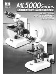
PHOTO TUBEADJUSTMENT RINGDIOPTER ADJUSTMENT RINGBINOCULAR BODY, INCLINED 30BEAM-SPLITTER LEVER(a) Field Iris Control Lever(b) Filter slots(c) Aperture Iris Control LeverEYEPIECES,KHW10XILLUMINATIONSERECTORANALYZER CONTROL LEVERVERTICAL ILLUMINATOROBJECTIVE NOSEPIECEOBJECTIVESLARGE SCAN 4” X 4”MECHANICAL STAGEWITH CLEAR GLASS PLATESUBSTAGE CONDENSERWITH IRIS DIAPHRAGM AND30MM FILTER TRAYSTAGE CONTROLSLIGHT SOURCEHOUSING FORREFLECTED LIGHTILLUMINATORMICROSCOPE LIMBFOCUS TENSIONCOARSE FOCUSCONTROLFINE FOCUSCONTROLON/OFF AND INTENSITYCONTROL FORTRANSMITTEDILLUMINATORILLUMINATOR CONDENSERMICROSCOPE BASE WITHBUILT-IN TRANSFORMERFIELD IRIS CONTROL FORTRANSMITTED LIGHTFILTERSTRANSFORMER BOXFOR REFLECTEDLIGHT ILLUMINATORWITH ON/OFF ANDINTENSITY CONTROLML85201
UNPACKING, ASSEMBLY, PREPARATION FOR USEUNPACKINGAll MEIJI TECHNO Microscopes are usually supplied in an expanded polystyrene, 2-part case and thisshould be used for storage, possible transport in the future, etc. If your order includes a woodenstorage cabinet, release the fixing screws holding the limb and base from the cabinet and withdraw.Unpack the microscope and its parts carefully. Do not throw away any boxes or packing materials untilcontents of the shipping container have been checked against your order and the packing list sent.ASSEMBLYTo mount the vertical illuminator (packed separately), loosen the clamp screw and insert the conefitting of the illuminator into the recess on the top of the limb and push the cone fitting toward andagainst the spring stopper gently until the illuminator slips into the position and fasten it with theclamp screw .Now, the binocular or trinocular body can be mounted on the vertical illuminator.To mount the body, loosen the clamp screw and insert the conefitting of the body into the recess on the top of the illuminator andfasten it with the clamp screw .Spring stopperVertical Illuminator(a)(b)Clamp screwClamp screwIlluminator plugPlace the microscope and parts on a sturdy table or desk which gives firm and stable support. Thisshould be located in the atmosphere as clean as possible, avoiding the places where there is excessivedust, moisture, heat or fumes.When in place insert eyepieces in the eyetubes of the binocular body and mount the objectives on theobjective nosepiece, starting with the lowest magnification, then positioning the others to the right of thenext lowest magnification objective.IMPORTANT!Before plugging the illuminator into any electric outlet, make sure that transformers and illuminationbases supplied to you are suitable to the current available. (See voltage indication given at the backbottom of the Limb.)2
OPERATING INSTRUCTIONSOPTICAL SET-UP AND BRIGHTFIELD ILLUMINATIONAfter connecting the illuminator plug to the receptaclefollow as indicated below:at the back of the microscope base, please[1] Turn on the illuminator. Place the specimen slide you wish to examine on the microscope stageand rotate the nosepiece to bring the 10X objective into position for focus.[2] Make sure that both the field iris(a) and the aperture iris (b) are fullyopen.Receptacle[3] Slide the Illumination Selector to the central position where the middle Empty Hole comesacross the Light Axis. This is the Brightfield Illumination.ILLUMINATION SELECTORSELECTOR LEVERAnalyzerSliderDarkfield stopperPolarizerEmpty hole for Brightfield[4] Pull the Analyzer Slide out to the full so the Analyzer gets out of the light path.[5] Focus down on your specimen slide until surface detail can be seen. Adjust the brightness of thebuilt-in light source, using the intensity control knob, left-hand back on the base.[6] BINOCULAR ADJUSTMENTComment: Using a binocular body is much more efficient and less tiring than monocular bodies, but itmust be adjusted correctly. When it is perfectly adjusted the images coming from the two eyepieces are“fused” into one better image in eyes of the observer.3
[7] After you have focused on the specimen, proceed as follows:-Move the sliders on which the two binocular eyepiece tubes are mounted inand out until the distance between them is exactly the same as thedistance between the pupils of the observers eyes. (This is the“interpupillary distance”.)Field of viewFused[8] When this is done, note the dimension which is displayed in the window of the slider. Alwaysremember to set to this distance when using the microscope. It will be different for different observers,so they will have to check the best setting for themselves.[9] To get best focus with both eyes the eyetube heights should be adjusted to take into account theinterpupillary distance mentioned [5] and [6] above. First, set the tube Length Adjustment Ring to thereading which corresponds to the dimension shown in the binocular slider window. Do this for the lefthand eyepiece only. Now focus to get the sharpest possible image in the left hand eyepiece, using themicroscope fine adjustment. Then turn the right hand Tube Length Adjustment Ring until the image isequally sharp in the viewer’s right eye.As these Rings function also for dioptricWindowcorrection the dimension set may not, inthis case, exactly correspond to theLength Adjustment Ringwindow’s indication.[10] Now turn the field iris adjustmentlever(a) until the field iris is seen in thefield of view.[11] Your light source may require centering adjustment if the field of view seems unevenly illuminated.Centering controls are located on the side of the light source housing which is built in at the back of thevertical illuminator.[12] CENTERING ADJUSTMENTTo move the bulb vertically, loosen ClampScrew and turn the Backing Plateclockwise or counterclockwise slightly.To move the bulb horizontally, turn theLamp Centering Control .Clamp screwBacking plateLamp centering control[13] Close down the filed iris (using thelever(a) on the vertical illuminator) until the image of the filed iris is in focus on the specimen. Thenopen it back out until the image of the iris disappears from the field of view.[14] Now adjust the aperture iris (using lever(b) on the vertical illuminator), closing it down slowly whileobserving the field of view. A point will be reached where there is a sudden distinct drop in brightnessof the field of view. When this occurs, open up the iris slightly, just until this brightness conditionreverses, but no more.4[15] This procedure should be followed each time objectives are changed.
DARKFIELD ILLUMINATION SET UPThe reflective Darkfield Illuminator is designed as shown here:As the above illustrates, the light does not pass the objectivedirectly and illuminate the specimen with the light bundle inclinedagainst the light axis, and observation is made possible onlythrough scattered or refracted light.When you observe flat surface of glass or mirror, you will see nothing in the dark. But, when youobserve a specimen which includes refractive substance to scatter light, the clear image of thesubstance can be seen.[1] Slide the IlluminationSelector to the positionwhere Darkfield stoppercomes across the LightAxis centrally.[2] Open up both irises forField(a) and Aperture(b).(a)[3] Focus down on the specimen just in the same way as for the Brightfield observation. (The image isobserved in a different way from that of the Brightfield observation. That is, we can see an imageformed from light scattered by features in the object, the detail thus appearing bright against a darkbackground.)[4] Brightness of illumination can be adjusted by Intensity Control knob, just in the same way as for theBrightfield observation.(b)Illumination SelectorDarkfield stopperPolarizerEmpty hole for BrightfieldPOLARIZING FACILITYPOLARIZERSlide the Illumination Selector to the position wherePolarizer comes across the Light Axis centrally.Darkfield stopperPolarizerEmpty hole for Brightfield5
SLIDE-IN ANALYZERThe Analyzer is mounted in an in-tube slider which moves the analyzer in and out of the optical pathand rotates between 0 and 90 by the lever . When “in” and at 45 position, and with thePolarizing filter in position, these elements are said to be “crossed” and the field of view is said to be“extinguished”. In this condition thefield of view is dark - except foroptically active elements in the field,which rotate the angle of polarizationAnalyzer slideAnalyzer rotatingand thus become visible against adark background.leverTRANSMITTED LIGHT ILLUMINATIONTo cover observation of both transparent and semi-transparent specimens, this series of metallurgicalmicroscopes are provided with a set of transparent glass stage plate, substage condenser and a semi-Koehler type 6V 30W Halogen lamp illuminator. The usage of the Transmitted Light illuminator is asfollows:[1] Place the specimen at the center of the stage plate, and switch on and control the light by simplyrotating the Intensity Control knob .[2] Lift up the substage condenser to the utmost by the Condenser Focusing Control and then openup the irises for Field and Aperture.[3] Focus down on the specimen, and also focus on the closed Field Iris itself. These two focusedimages of the specimen and the closed Iris are seen overlapped. Then, open the Field Iris slowlyuntil the field of view comes to cover the whole image of the specimen. Reduce the Aperture slowlyuntil you can view the image in the best appearance. Too much reduction of Aperture Iris is not goodas the resolution capacity gets much less due to the roughened image. (By the way, the closed FieldIris can not be seen through 100X objective.)Tension control knobCondenser centeringscrewAperture Iris & ControlleverIntensity Control knobCondenser FocusingControlField Iris & Control6
TENSION CONTROLThe tension control knob is provided to allow the individual user to adjust the focus tension to his/herown preference. Tension may be increased by turning the knob with a counterclockwise motion.A lighter tension may be set by turning clockwise.PHOTOGRAPHY AND TELEVISIONPHOTOGRAPHYPhotographic documentation of microscope visual images is most conveniently achieved by using thetrinocular (photo-binocular) bodies for use with 35mm SLR Camera or PMX100 Large Format Camera.In the case of the ML series of biological, metallurgical and polarizing microscopes a trinocular body isequipped with a sliding switch-over beam-splitter component which either (1) allows all of the light to goto the visual eyepieces or (2) directs 80% of the image-forming light upwards to the film plane of a35mm SLR camera, while still sending 20% of the light to the binocular eyepieces.In the system the MA150/50 or MA150/60 Camera Attachment should be used with the SLR camera ofyour choice. Please note that one of the large range of T2 Adaptor Rings suiting to your camera shouldbe ordered separately.These adaptor rings are intended to compensate for the small differences in effective distance of thefilm plane in your camera - so as to ensure that photographs are optimally sharp, and achieved withoutwastage of film in trial shots and experimentation.In addition special low-power camera eyepieces (2.5X, 3.3X and 5X) are available and recommended -these will give you maximum field coverage on your specimen while using the convenient andeconomical 35mm film format.CAMERA OPERATION[1] Fix your 35mm SLR camera, T2 Adapter and a photo (camera) eyepiece on the MA150/50 orMA150/60 Camera Attachment, then mounting this assembly on the straight tube of the trinocular body.[2] Pull out the lever on your trinocular body so as to send the image both to the camera and the visualeyepieces.7
[3] Rotate the adjustment ring on the straight tube so as to set correctly for optimum conditions ofsimultaneous visual observation and photography.TELEVISIONFor television the MA151/10 C Mount should be used, threaded into your TV camera, then placedand adjusted on straight tube of your trinocular body.Adjustment can then proceed as per paragraph [3] above. You should understand that thecomparatively large magnification factors inherent in most TV camera/monitor systems will restrict yourfield of view (while blowing up total magnification).A correct optical set-up and adjustment is, of course, crucial to obtaining a good TV monitor image, butkeep in mind that the monitor controls for brightness and contrast adjustment are also important andshould also be experimented with in order to obtain the best monitor image.MAINTENANCE AND CAREBULB REPLACEMENT ON REFLECTED LIGHT ILLUMINATORWhen changing light bulbs in the illuminators, always disconnect the plug from the electrical source.Never work on the electrical system without first disconnecting.The bulb is held in a socket block inserted in the light source housing at the back of the verticalilluminator.[1] To remove the socket block from the lightsource housing, loosen the Clamp Screw andturn the Backing Plate clockwise to the slot.Then pull out the Backing Plate from the lightsource housing.Clamp screwBacking plateLamp centeringcontrol[2] After making certain the old bulb is cool to the touch, remove it by pulling straight out of its socket.Do not twist as the lamp pins may break off and become lodged in the socket.[3] Handle the new bulb only with tissue paper or the plastic in which it is wrapped and insert the twopins into the two holes in the socket.8
BULB REPLACEMENT ON TRANSMITTED LIGHT[1] Remove the socket block from the microscope base by unscrewing the two screws and pulling thebacking plate clear of the instrument.[2] After making certain the old bulb is cool to thetouch, remove it by pulling straight out of its socket.Do not twist as the lamp pins may break off andbecome lodged in the socket.[3] Handle the new bulb only with tissue paper orthe plastic in which it is wrapped and insert the twopins into the two holes in the socket.Socket BlockScrewDO NOT HANDLE WITH BARE FINGERS - BULB MAY EXPLODE WHEN HEATED IF NOTHANDLED CORRECTLY.CAREAlways cover the instrument with plastic dust cover provided when the microscope is not in use.Keep eyepieces in the microscope body at all times in order to prevent dust from falling on the internaloptics.Store the microscope in a safe, clean place when not in use for an extended period of time.CLEANINGClean exposed lens surfaces carefully with a pressurized air source, soft brush or clean soft cloth. Toomuch finger pressure may damage lens coatings.To remove oil, fingerprints and grease smudges, use the cleaning cloth moistened with a very smallamount of alcohol or xylene.Immersion oil should always be promptly cleaned from high power oil immersion objectives after everyuse.Painted or plastic surfaces should be cleaned only with a cloth moistened with water and a smallamount of detergent.DO NOT ATTEMPT TO MAKE ADJUSTMENTS TO THE INTERNAL OPTICS OR MECHANICS!!If the microscope does not seem to be functioning properly or you have questions about its operation,call your supplier (or/and authorized repair service) for advice.9
6, Oi-670, Oi-machi, Iruma-gunSaitama 356, JapanPhone : 492-67-0911Fax : 492-69-0691, 492-69-06922186 Bering DriveSan Jose, CA., 95131, USAPhone : 408-428-9654 Fax : 408-428-0472Toll free : 800-832-0060 97.07.1,000 Printed in Japan