INTERPRETATION OF AXIAL PILE LOAD TEST RESULTS FOR ...
INTERPRETATION OF AXIAL PILE LOAD TEST RESULTS FOR ...
INTERPRETATION OF AXIAL PILE LOAD TEST RESULTS FOR ...

You also want an ePaper? Increase the reach of your titles
YUMPU automatically turns print PDFs into web optimized ePapers that Google loves.
Emerging Technologies in Structural Engineering<br />
th<br />
Proc. of the 9 Arab Structural Engineering Conf., Nov. 29 – Dec. 1, 2003, Abu Dhabi, UAE<br />
<strong>INTERPRETATION</strong> <strong>OF</strong> <strong>AXIAL</strong> <strong>PILE</strong> <strong>LOAD</strong> <strong>TEST</strong> <strong>RESULTS</strong><br />
<strong>FOR</strong> CONTINUOUS FLIGHT AUGER <strong>PILE</strong>S<br />
G. E. ABDELRAHMAN, E. M. SHAARAWI, AND K. S. ABOUZAID<br />
Department of Civil Engineering, Faculty of Engineering, Cairo University<br />
Fayoum Branch.-Fayoum<br />
ABSTRACT: Axial pile loading tests on single piles may offer the justification of the pile design<br />
load and the installation procedure. Codes of deep foundations stipulate the acceptance criteria for<br />
piles tested in compression based on specified limits for pile settlement at specified load levels.<br />
The objectives of this paper are to examine the different methods used in interpreting pile load test<br />
results and choose the most reliable method for interpreting the results of the tests for piles in<br />
Egyptian soil. Sixty-four continuous flight auger piles were tested using the maintained load test<br />
method and the results were analyzed using the different methods of interpretation.<br />
INTRODUCTION<br />
The available methods of interpretation of the load test results rely on predicting the failure load or<br />
limit load by applying mathematical or graphical techniques, and applying a proper factor of safety<br />
to get the pile working load. Hence it is important to determine the ultimate or limit load as<br />
accurately as possible. The Egyptian Code of Deep Foundations (ECDF) employs certain criteria<br />
governing the acceptance of tested piles based on specified limits for pile settlement at specified<br />
load levels. A pile is considered acceptable if the observed settlement of pile head is within these<br />
limits. A comparison between the different methods of interpreting pile load test results is made to<br />
determine the most suitable to use for continuous flight augers piles in Egypt.<br />
The working or design load is that the pile is designed to carry safely within a limited range<br />
of settlement. This range depends on the nature of the building, its importance and also the<br />
properties of soil in which the pile is installed. The design load is pre-calculated using field and<br />
laboratory test results. Load tests are performed to proof the design load and check the pre-chosen<br />
factor of safety. Six different definitions of pile capacity evaluated from load-movement records of<br />
static loading tests are presented. Five of these are of particular interest, namely, Davisson’s,<br />
Hansen’s, Modified Chin’s, De Beer’s, and Mazurkiewicz’s methods. Recently, Luciano Decourt<br />
in Brazil proposed a sixth method. These methods, including the Decourt’s Extrapolation method<br />
are used in the above mentioned comparison.<br />
<strong>PILE</strong> <strong>LOAD</strong> <strong>TEST</strong>S<br />
The loading tests generally followed the ECDF, (part 4) procedures, reaching a maximum load of<br />
about one and half to two times the design load. Each increment is maintained until the rate of<br />
settlement measured at the pile head becomes equal to or less than 0.15 mm/hour or maintained a<br />
specified time according to Table 1 whichever occurs first. The pile is unloaded at a rate of 15 minutes<br />
each, the pile is left free without any loads for 4 hours.<br />
791
Table 1 Load increment-Time<br />
<strong>LOAD</strong> INCREMENT, % <strong>OF</strong> DESIGN <strong>LOAD</strong> 25 50 75 100 125 150<br />
Times, hours 1 1 1 3 3 12<br />
<strong>PILE</strong> <strong>LOAD</strong> <strong>TEST</strong>S DATA<br />
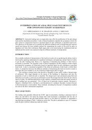
A database of sixty four axial static loading tests on continuous flight auger piles at different sites<br />
was compiled. Pile diameters range from 0.30 m to 1.08 m, and penetration depths range from<br />
11.2 to 34 meters. The tests were carried out at 20 different sites. Generally, the database of<br />
loading tests is representative of a wide range of piles in Egypt. Figure 1 shows a sample of loadsettlement<br />
curves for some pile load tests used in this study, from seven different sites. The<br />
sequence in all tests was in accordance with the procedures specified in the ECDF, Part 4 (1995)<br />
for conducting the maintained load test. All pile load test results were analyzed using the six<br />
different interpretation methods mentioned above<br />
Settlement, S (mm)<br />
Load, Q (ton)<br />
0 50 100 150 200 250 300 350 400 450 500 550<br />
0<br />
4<br />
8<br />
12<br />
16<br />
20<br />
Davisson’s Method<br />
pile no. 1<br />
pile no. 2<br />
pile no. 3<br />
pile no. 4<br />
pile no. 5<br />
pile no. 12<br />
pile no. 26<br />
Figure 1: Load – Settlement curve for Sample of pile load tests<br />
from different sites<br />
Davisson’s Offset Limit Method (ultimate load) offers the benefit of allowing the engineer, when<br />
proofing a pile for a certain allowable load, to determine in advance the maximum allowable<br />
movement for this load with consideration to the length and size of the pile. The method is<br />
illustrated in Figure 2 for pile no.1. The pile load settlement curve is plotted to a convenient scale,<br />
so that the line represents the relationship between the load and shortening of an elastic free axially<br />
loaded column, ∆ makes an angle of about 20 degrees with the load axis. It can be calculated from<br />
following equation:<br />
∆ = Q L / A E (1)<br />
Where, Q is the applied load, L is the length of the pile, A is the cross section area of the pile, and<br />
E is the modulus of elasticity of pile material. The offset limit load straight line is plotted parallel<br />
to the elastic line to intersect the load movement curve. Where OC of Figure 2 is given by:<br />
OC = 3.8 + D / 120 (2)<br />
792
Where, D is the pile diameter in mm. The load movement curve intersects the line at point C, the<br />
ordinate of which is 0.9 Qu according to the ECDF. This method provides a failure load value that<br />
tends to be conservative without dividing by the factor of 0.9 according to the ECDF that reduces<br />
the conservatism of the method.<br />
A primary advantage of this method is that the actual limit line can be drawn on the load<br />
movement diagram already before starting the test. The offset limit load criterion is primarily<br />
intended for interpretation of quick testing methods, but it can also be used when interpreting results<br />
from the slow methods. It is not suitable for testing methods that involve loading and unloading<br />
cycles.<br />
The Davisson Offset Limit is very sensitive to errors in the measurements of load and<br />
movement and requires well-maintained equipment and accurate measurements. However, it is easy<br />
to apply and has gained wide acceptance. The disadvantage of the offset limit load lies in the<br />
difficulty of determining the modulus of elasticity E for concrete piles and concreted pipe piles. This<br />
method has been applied to just 4 pile load tests of the database, for other tests, the failure load<br />
cannot be defined. Davisson's method needs the pile to be loaded to failure to be applicable.<br />
Settlement S (mm)<br />
Load, Qu (ton)<br />
0 50 100 150 200 250 300 350<br />
0<br />
0.9 Qu = 320 ton<br />
4<br />
8<br />
12<br />
16<br />
20<br />
Figure 2: Ultimate failure load according to Davisson For pile no. 1<br />
Brinch Hansen’s method (80% criterion)<br />
The load that gives four times the movement of the pile head as obtained for 80 % of that load can<br />
be estimated directly from the load-movement curve, but it is more accurately determined in a plot<br />
of the square root of each movement value divided by its load value and plotted against the<br />
movement. The method is illustrated in Figure 3 where the pile load movement curve is plotted for<br />
pile no. 1; the data is fitted to a straight line. After determining the slope C1, and y-intercept C2 of<br />
the plotted line, the ultimate failure load Qu and ultimate settlement Su are calculated as follows:<br />
Qu = 1 / (2√C1C2) (3)<br />
Su = C1 / C2 (4)<br />
In many cases the calculated 0.8 Qu doesn’t intersect the observed curve, because it is more<br />
than the test load. The 80 % criterion determines the load-movement curve for which the Hansen<br />
plot is a straight line throughout. The equation for this calculated curve is shown on Figure 3, Eq.<br />
4 gives the relation for the calculated curve.<br />
Q = √S / [C1 S + C2] (5)<br />
793<br />
oc
Where: Q = applied load, and S = movement. When using the Hansen 80%-criterion, it is<br />
important to check that the point (0.80 Qu, and 0.25 S) lies on or near the measured loadmovement<br />
curve. According to Eq. 5 on the observed load-movement curve, the two curves should<br />
preferably nearly coincide between the load equal to about 80 % of the Hansen ultimate load and<br />
the ultimate load itself.<br />
This method is applied in cases, where the pile is loaded near to failure. This method is<br />
applied to 33 piles load tests only. Just 11 piles of the 33 were checked for coincidence of the point<br />
(0.8 Qu, 0.25 S) in both actual and calculated curves, but the others have 0.8 Qu value more than<br />
the test load. Except for the 33 mentioned piles, the slope of the obtained line from regression<br />
analysis is negative resulting in imaginary square root.<br />
Load Q (ton)<br />
350<br />
300<br />
250<br />
200<br />
150<br />
100<br />
50<br />
0<br />
Calculated Q -S curve<br />
Observed Q -S curve<br />
Sqrt (S) / Q vs S<br />
794<br />
y = 0.0003 x + 0.0078<br />
R 2 = 0.9702<br />
0 2 4 6 8 10 12 14 16 18 20<br />
Settlement S (mm)<br />
Figure 3: Ultimate failure load according to Brinch Hansen 80% criterion for pile no. 1<br />
Chin-Kondner and Modified Chin Methods<br />
Chin assumes that the relationship between load and settlement is hyperbolic. In this method each<br />
settlement value is divided by its corresponding load value. These are plotted against the<br />
settlement. The plotted values lie on a straight line approximately. The inverse slope of the straight<br />
line indicates Chin–Kondener Extrapolation Limits. This method was used to determine the loadmovement<br />
curve for which the Chin-Kondner plot is a straight line throughout. The calculated<br />
curve is shown in Figure 4 and it is given by the following equation:<br />
0.02<br />
0.01<br />
0.00<br />
S/Q = C1 S + C 2 (6)<br />
Where: S = settlement of pile at pile load Q; C1, and C2 = slope and Y-axis intercept of the<br />
straight line, respectively. The Chin-Kondner limit load is of interest when judging the results of<br />
static loading tests, particularly in conjunction with the values determined according to Davisson’s<br />
and Hansen’s methods. Chin’s method is affected by the limit of loading, as the pile is loaded near<br />
failure the greater predicted value of ultimate load , this can be seen in pile no. 1, if the last two<br />
readings are omitted the resulting ultimate load value will be reduce by about 4%. Note that some<br />
analysts use the Chin-Kondner Extrapolation Limit as the pile capacity, after applying a suitably<br />
large factor of safety, this approach is not advisable. One should not extrapolate the results when<br />
determining the allowable load by dividing the extrapolated capacity by a factor of safety.<br />
Therefore, the ECDF, Part 4, 1991 reduces the resulting Chin-Kondner Extrapolation ultimate load<br />
by dividing it by 1.2.
Load, Q (ton)<br />
350<br />
300<br />
250<br />
200<br />
150<br />
100<br />
50<br />
0<br />
795<br />
y = 0.0027x + 0.0073<br />
R 2 = 0.9954<br />
Observed Q - S curve<br />
Calculated Q - S curve<br />
S/Q vs S<br />
0 2 4 6 8 10 12 14 16 18 20<br />
Settlement S, (mm)<br />
Figure 4: Ultimate failure load according to Chin- Kondner’s extrapolation for pile no. 1<br />
It is found that the Chin–Kondener extrapolation ultimate load is 5% to 37% greater than the<br />
Davisson ultimate load, with average of 17% for the four pile load tests that Davisson’s method is<br />
applied to. Also, Chin–Kondener extrapolation ultimate load is 6% greater than Hansen’s ultimate<br />
load on average for the 33 pile load tests that B. Hansen’s method is applied to, but with a<br />
different range, from -23% to 33%, excluding the two highest and lowest differences. This method<br />
is applied to all tests analysed in this study, it is illustrated in Figure 4 for Pile no.1.<br />
Mazurkiewicz’s Method<br />
Bengt (1980) suggested this method which is based on the assumption that the load–settlement<br />
curve is approximately parabolic. A series of equal pile head settlement lines are arbitrary chosen<br />
using equal intervals and the corresponding loads are marked on the abscissa, as shown in Figure<br />
5. For the marked loads on the load axis, a 45-degree line is drawn to intersect with the next<br />
vertical line running through the next load point. These intersections fall approximately on a single<br />
straight line, the intersection of this line with the load axis defines the ultimate failure load.<br />
Smaller settlement interval may introduce more accurate results.<br />
It is simple in its construction, more reliable especially for piles loaded near failure. From test<br />
results it is found that this method predicts ultimate failure loads equal to that predicted by<br />
Davisson's method and less by 18% than Hansen’s methods on average. Also this method is 28%<br />
less than that of Chin results on average. This method has been applied to all pile load tests in this<br />
study.<br />
Settlement S (mm)<br />
0 50 100 150 200 250 300 350 400<br />
0<br />
5<br />
10<br />
15<br />
20<br />
Load Q (ton)<br />
Figure 5: Ultimate failure load according to Mazurkiewicz for pile no. 1<br />
0.06<br />
0.05<br />
0.04<br />
0.03<br />
0.02<br />
0.01<br />
0<br />
Ultimate failure<br />
load = 355 ton
De Beer’s method<br />
In this method, the load–settlement values were plotted on a double logarithmic chart. When the<br />
values fall on two approximately straight lines, the intersection of these defines a limit load that is<br />
considered a pile yielding load. The method is illustrated in Figure 6 for pile no. 1, as an example<br />
pile.<br />
Regarding the results a new definition must be introduced for this method namely yielding<br />
limit load. All previously mentioned methods determine a failure load except De Beer. Therefore,<br />
one should distinguish between the failure load and the limit load to adopt the proper factor of<br />
safety. The pile failure load, which predicted from load–settlement relationships of piles loaded to<br />
pre-failure are based on assuming certain shapes of these relationships independent of pile<br />
geometry, soil properties, and rate of loading. But the limit load is the load at which the curve<br />
begins to be steeper sloped and enters into the plastic behavior zone. This method needs the pile to<br />
be loaded near failure, because when the pile is not loaded near failure, the plotted values of the<br />
load settlement fall on approximately one straight line and the limit load is not defined.<br />
Settlement S (mm)<br />
0.1<br />
Figure 6: Yielding limit load for pile no. 1<br />
De Beer’s method is applicable only to 49 pile tests in this study. From the results it is found<br />
that no comparison can be done because the large difference of factor of safety in this method<br />
compared with all other methods, this is because it predicts the yield limit load but others predict<br />
ultimate failure load.<br />
Decourt’s Extrapolation Method<br />
1<br />
10<br />
100<br />
Load Q (mm)<br />
1 10 100 1000<br />
This method is applied by dividing each load by its corresponding movement and plotting the<br />
resulting values against the applied load. Figure 7 shows the result for pile no. 26, as an example<br />
pile. The part of the curve that tends to a straight line intersects the load axis. Linear regression<br />
over the apparent straight-line determines the required slope C1 and y- intercept C2 constants.<br />
Decourt’s ultimate load is the value at the intersection with the load axis, Decourt’s ultimate load<br />
Qu can be accurately calculated as the ratio between the y- intercept and the slope of the line as<br />
given in Eq. 7.<br />
Qu = C2 / C1 (7)<br />
796<br />
Limit load =143
Load / Settlement<br />
120<br />
100<br />
80<br />
60<br />
40<br />
20<br />
0<br />
797<br />
y = -0.4185x + 108.3<br />
R 2 = 0.9967<br />
0 50 100<br />
Load, (ton)<br />
150 200 250<br />
Figure 7: Decourt’s Extrapolation Method for pile no. 26<br />
As shown in Figure 8, the load-movement curve can be calculated and compared to the actual<br />
load-movement curve of the test as follows:<br />
Settlement S (mm)<br />
Q = C2 S / [1-(C1 S)] (8)<br />
Load (ton)<br />
0 50 100 150 200 250<br />
0<br />
3<br />
6<br />
9<br />
12<br />
Observed q-s curve<br />
Calculated q-s curve<br />
Figure 8: Observed and calculated curves by Decourt Extrapolation for pile no.26<br />
The results from using Decourt’s method are very similar to those of the Chin Kondner's<br />
method. Decourt’s ultimate load is of interest when judging the results of a static loading test,<br />
particularly in conjunction with the values determined according to Davisson’s and Hansen’s<br />
methods. Although some analysts use Decourt's Extrapolation limit as the pile capacity established<br />
in the test (with an appropriate factor of safety), this approach is not advisable for the same reason<br />
mentioned in Chin-Kondner’s method. As the ECDF modified the Chin – Kondner ultimate load<br />
dividing by a factor of 1.2, if this method is used in Egypt it should be modified by dividing the<br />
resulting ultimate failure load by a factor of 1.16.<br />
The method is applicable to all pile load tests in this study. Results obtained from this method<br />
are 16% greater, on average, than those obtained from the Chin–Kondner extrapolation method.<br />
Comparing this method with Davisson’s, it yields results that are greater by 10%. While<br />
comparing this method’s results with B. Hansen’s method it is found that these are only 3%<br />
greater on average for 33 of the pile load tests. Also this method’s results are 42% greater than<br />
Mazurkiewicz’s results for ultimate load.
SUMMARY<br />
The ultimate load capacity Qu for each pile test was predicted using the six methods stated above<br />
that are used in the evaluation of the pile load test. All these methods determine failure load except<br />
De Beer, which is determines the yield limit load. Sixty-four pile load tests were analyzed to get<br />
the ultimate failure, limit load, and the factor of safety for each pile load test by each method. A<br />
comparison between various ultimate loads or limit loads may be made from the results listed in<br />
Table 2.<br />
From Table 2 it can be seen that Davisson’s methods is applicable just to four pile load<br />
tests, i.e. 6.3%, of all analyzed cases, while Hansen’s, Chin’s, Mazurkiewicz’s, De Beer’s and<br />
Decourt’s methods were applicable to 33, 64, 64, 49 and 64 tests, representing 55%, 100% ,100%,<br />
76.5% and 100% respectively, of all analyzed cases, i.e. the only three methods which are<br />
applicable to all pile load tests are, Chin’s, Mazurkiewicz’s, and Decourt’s methods.<br />
Table 3 below, gives the range and average of factor of safety calculated using<br />
each method for predicting ultimate load, while De Beer’s method is not included in the average<br />
ultimate load. For De Beer’s method the ratio of limit load by working load range from 1.04 to<br />
1.75 and the average of this ratio is 1.31.<br />
CHOICE <strong>OF</strong> EVALUATION METHOD<br />
It is difficult to make a choice of the best axial load capacity criterion to use, because the preferred<br />
criterion depends heavily on one's experience and conception of what constitutes the ultimate<br />
resistance of a pile to failure.<br />
Davisson’s method tends to be conservative. It is not suitable for testing methods that involve<br />
loading and unloading cycles.<br />
Brinch-Hansen 80%-criterion usually gives ultimate load, which is close to what one<br />
subjectively accepts as the true ultimate resistance determined from the results of the static loading<br />
test.<br />
The Chin-Kondner Extrapolation and the Decourt Extrapolation limit load values are<br />
approached asymptotically. Therefore, the two methods always obtained the ultimate load by<br />
extrapolation. It is a sound engineering rule never to interpret the results from a static loading test<br />
to obtain an ultimate load larger than the test load. For this reason, an allowable load must not, be<br />
determined by dividing the limit loads according to Chin-Kondner’s and Decourt’s methods by a<br />
factor of safety.<br />
Mazurkiewicz ultimate load values are the most conservative results, less than the values<br />
which are obtained using Davisson, Hansen, Chin, and Decourt methods. It is simple in its<br />
construction, more reliable especially for piles loaded near failure.<br />
De Beer’s method, the shortcomings of this method have been outlined above. Hansen's 80%criterion,<br />
Chin’s and Decourt’s extrapolation methods allow the latter part of the load-movement<br />
curve to be extrapolated beyond the maximum load applied.<br />
Decourt’s method is the most recent method; it is very similar Chin Kondner’s method.<br />
Decourt’s method has the advantage that a plot can be prepared while the static loading test is in<br />
progress, that will allow the user to eyeball the projected capacity directly once a straight line plot<br />
starts to develop. As in the Chin-Kondner’s method, if during the progress of a static loading test,<br />
a weakness in the pile develops, the curve would show a kink. Therefore, there is considerable<br />
merit in plotting the readings as per Decourt’s method as the test progresses. The two methods<br />
predict a reasonable ultimate failure loads but need to be modified by dividing by a factor (1.16-<br />
1.2) as is stipulated in the ECDF for the modified Chin method.<br />
798
Site<br />
No.<br />
Pile<br />
No.<br />
Table 3 Summary of predicted ultimate failure loads and De Beer limit load<br />
Davisson Hansen Chin Mazur. De Beer Decourt<br />
799<br />
Test<br />
Load<br />
Qu (ton) Qu (ton) Qu (ton) Qu (ton) QL.L (ton) Qu (ton) Qu (ton)<br />
1 1 344.40 326.86 308.64 355.00 143.00 371.02 333<br />
2 2 674.20 555.56 560.00 420.00 605.82 480<br />
3 3 522.20 524.11 580.00 455.00 605.50 520<br />
4 597.61 595.24 490.00 402.00 647.58 460<br />
4<br />
5 520.83 540.00 634.92 460<br />
5<br />
6<br />
7<br />
8<br />
9<br />
9<br />
10<br />
11<br />
6 252.53 128.00 93.00 262.16 113*<br />
7 134.30 214.22 130.00 93.50 255.45 113*<br />
8 227.04 185.19 175.00 148.00 220.91 170*<br />
9 270.37 177.30 160.00 107.00 220.97 150*<br />
10 252.54 177.30 157.00 125.00 198.98 150*<br />
11 191.18 185.19 205.00 150.00 229.00 180*<br />
12 211.10 191.18 184.37 205.00 108.00 193.88 200<br />
13 213.98 213.68 195.00 128.00 256.94 180*<br />
14 238.91 193.80 190.00 125.00 229.10 180*<br />
15 252.53 240.00 149.00 286.89 210*<br />
16 345.03 238.10 200.00 126.00 285.00 180*<br />
17 280.39 203.25 205.00 128.00 231.75 180*<br />
18 279.51 297.62 225.00 367.93 210<br />
19 243.98 289.35 220.00 160.00 320.86 210<br />
20 231.13 240.15 230.00 160.00 283.64 210<br />
21 391.24 260.00 183.00 471.59 210<br />
22 396.83 240.00 423.96 210<br />
23 396.83 250.00 430.30 210<br />
24 333.33 250.00 374.27 210<br />
25 302.61 260.42 260.00 150.00 321.24 210<br />
26 244.40 237.29 219.30 220.00 258.78 210<br />
27 362.32 240.00 420.99 210<br />
28 396.83 250.00 475.30 210<br />
29 378.79 270.00 449.20 210<br />
30 231.48 198.00 140.00 280.10 160<br />
31 163.40 158.00 186.96 120*<br />
32 277.78 188.00 328.57 120*<br />
33 297.62 176.00 344.94 120*<br />
34 163.40 166.00 183.19 120*<br />
35 148.81 92.00 165.15 72*<br />
36 85.84 92.59 83.00 60.00 112.24 72*
Site<br />
No.<br />
Table 3 Summary of predicted ultimate failure loads and De Beer limit load (continued)<br />
Pile<br />
No.<br />
Davisson Hansen Chin Mazur. De Beer Decourt<br />
800<br />
Test<br />
Load<br />
Qu (ton) Qu (ton) Qu (ton) Qu (ton) QL.L(ton) Qu (ton) Qu (ton)<br />
38 70.43 60.39 72.00 35.00 67.69 60<br />
39 104.28 75.76 68.00 35.00 85.47 60<br />
40 118.38 54.82 58.00 40.00 58.46 50*<br />
12 41 60.83 55.00 32.00 76.47 45*<br />
42 55.93 52.00 32.00 70.42 45*<br />
43 177.30 120.00 75.00 201.64 90*<br />
44 134.41 140.00 162.13 90*<br />
45 100.81 94.70 102.00 66.00 115.00 96<br />
46 56.50 60.83 44.00 35.00 68.89 40<br />
47 85.03 47.00 35.00 88.89 40<br />
13<br />
48<br />
49 64.73<br />
128.21<br />
71.84<br />
105.00<br />
50.00 35.00<br />
152.20<br />
86.00<br />
96<br />
40<br />
50 50.20 42.00 25.00 60.23 30*<br />
51 44.09 44.00 25.00 50.00 30*<br />
52 41.46 44.81 25.00 50.95 30*<br />
14<br />
53<br />
54<br />
41.67<br />
44.95<br />
37.71<br />
37.04<br />
42.00<br />
41.00<br />
25.00<br />
25.00<br />
43.90<br />
44.84<br />
30*<br />
30*<br />
55 53.39 37.88 38.00 25.00 43.20 30*<br />
56 231.48 115.00 81.25 277.78 97.5*<br />
15 57<br />
58 248.45<br />
213.68<br />
190.69<br />
110.00<br />
150.00<br />
81.25<br />
95.00<br />
231.99<br />
215.22<br />
97.5*<br />
135*<br />
59 265.75 170.42 160.00 95.00 215.38 135*<br />
17 60 177.30 169.00 110.00 205.33 150*<br />
18 61<br />
62<br />
204.12 208.33<br />
305.25<br />
162.00<br />
165.00<br />
125.00<br />
150.00<br />
220.98<br />
348.89<br />
150*<br />
150*<br />
19 63 124.38 75.00 40.00 148.98 55.5*<br />
20 64 239.73 157.23 165.88 125.00 194.85 150*<br />
*: Denoted to load test equal one and half the working load.<br />
Table 4: Range and average of factor of safety<br />
Method Davisson Hansen Chin Mazur. Decourt<br />
Factor of Safety Ranges 2 : 3 1.6 : 4 1.5 : 4.3 1.6: 3.1 1.6: 4.6<br />
Average Factor of Safety 2.4 2.5 2.5 2 2.9<br />
CONCLUSIONS<br />
(1) The only three methods applicable to all tests used in the study are Chin’s, Mazurkiewicz’s,<br />
and Decourt’s methods.<br />
(2) The methods of B. Hansen, Chin, and Decourt use regression analysis for predicting the<br />
failure load, and can reach results without loading to failure.
(3) Davisson’s, and DeBeer’s methods needs the pile to be loaded to failure to be applicable.<br />
(4) The most convenient methods to be applied and that give reasonable results are Chin’s,<br />
Mazurkiewicz’s, Decourt’s, and Brinch Hansen’s methods.<br />
(5) Ultimate load results predicted by Decort’s method should be reduced by 16% in case of using<br />
this method in Egypt.<br />
REFERENCES<br />
1. Davisson, M. T., “High capacity piles". Proceedings of Lecture Series on Innovations in<br />
Foundation Construction, American Society of Civil Engineers, ASCE, Illinois Section,<br />
Chicago, March 22, pp. 81 112, 1972.<br />
2. Branch-Hansen, “Discussion on Hyperbolic Stress-Strain Response”, American Society of Civil<br />
Engineering, ASCE, Journal for Soil Mechanics and Foundation Engineering, Vol.97, SM6,<br />
pp.931-932. 1963<br />
3. Chin, F.K. “Estimation of the Ultimate Load of Piles Not Carried to Failure”, Proc.2 nd<br />
Southeast Asia. Conference on soil Engineering, pp. 81-90, 1970.<br />
4. Debeer, E. E., "Proefondervindlijke bijdrage tot de studie van het grensdraag vermogen van zand<br />
onder funderingen op staal." Tijdshift der Openbar Verken van Belgie, No. 6, 1967 and No. 4, 5,<br />
and 6, 1968, Quoted from Ref. 10<br />
5. Bengt, H.F. "The Analysis of Results from Routine Pile Load Tests", Ground Engineering, pp.19-<br />
31, 1980.<br />
6. Decourt, L., “Behavior of foundations under working load conditions”. Proceedings of the<br />
11th Pan-American Conference on Soil Mechanics and Geotechnical Engineering, Foz-<br />
DoIguassu, Brazil, August 1999, Vol. 4, pp. 453 488, 1999.<br />
7. Egyptian Code of Soil Mechanics and Foundation Engineering,, 4 TH part -Deep Foundation,<br />
(1995)<br />
8. Kondnr R.L., “Hyperbolic Stress-Strain Response, in Cohesive Soils,” American Society of<br />
Civil Engineering, ASCE, Journal for Soil Mechanics and Foundation Engineering, Vol.89, SM1,<br />
pp.115-1493, 1963.<br />
9. Canadian Geotechnical Society, "Canadian Foundation Engineering Manual.” 1992.<br />
10. Fellenius, B.H. “ What Capacity Value to Choose from the Results of a Static Loading Test”,<br />
Fulcrum, Deep Foundation Institute, New Jersey, 2001.<br />
801
802