
You also want an ePaper? Increase the reach of your titles
YUMPU automatically turns print PDFs into web optimized ePapers that Google loves.
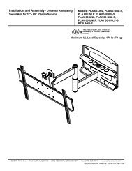
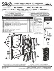
88 9001 002 CCuisine Cart (White)IMPORTANT NOTECarefully remove all the parts from the carton and putthem individually on a soft cloth to prevent scratchesor other damages occuring to the wood parts.We have taken great care in the design of thisproduct and request that you carefully and strictlyfollow our assembly instructions to ensure acompleted product as it was designed.PART LISTCasual Attire For Today's HomeThai Patent Numbers 067953A.Side Panel1 pc.F.BackStretcher1 pc.G.Front Rail1 pc.B.Side Panel1 pc.H.Side Rack1 pc.C.Base1 pc.D.Back Piece1 pc.I.Side Rack1 pc. J.Brush Chrome Pipes3 pcs.E.Back Panel2 pcs.K.Base Rack1 pc.L.Side Towel Bar1 pc.M.Shelf1 pc.N.Door.1 pc.O.Door.1 pc.P.Drawer1 pc.HARDWARE LISTHex Wrench1 pc.Head Cap Bolt (Middle)for top4 pcs.(+ 1 extra)Pull Handle2 pcs.Wood Screw16 pcs.(+ 1 extra)Castertwo locktwo non-lock4 pcs.Head Cap Bolt (short)for Side Towel Bar2 pcs.(+ 1 extra)Head Cap Bolt(long)12 pcs.(+ 1 extra)Machine Screwfor Pull Handle4 pcs.Adjustable Pin4 pcs. (+ 1 extra)Wood Plug8 pcs.(+2 extra)Tools Required For <strong>Assembly</strong> : Philips screwdriver
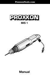
IMPORTANTDo not tighten up all the screws until each part is properly assembled.You should keep Hex Wrench in the safe place as you may need totighten up the Head Cap Bolts in the future.<strong>Assembly</strong> <strong>Instructions</strong> 2/4STEP 1Attach four Casters tothe underneath of the Base (C).Wood ScrewCLocking CasterLocking CasterDSTEP 2Attach the Side Panel (B) to theBase (C).Tighten up the Head Cap Bolts.BAttach the Back Piece (D) on the Base rear.CTighten HeadCap Bolt byHex Wrench.Head Cap Bolt
<strong>Assembly</strong> <strong>Instructions</strong> 3/4FHead Cap BoltAEESTEP 3Slide the Back Panel (E) in place.GBAttach the Back Stretcher (F) on the unitwith the Head Cap Bolt.Attach the Front Rail (G) to theSide Panel (B) with Head Cap Bolt.Attach the Side Panel (A) to the unit withHead Cap Bolts.Head Cap BoltJHead Cap BoltSTEP 4AAttach the Side Rack (H) to the Side Panel (A)with the Head Cap Bolts.HAttach the Brush Chrome Pipes (J) to the pre-drilledholes of Side Rack (H).Attach the Base Rack (K) to the Side Rack (H).KJIAttach the Side Rack (I) to the Side Panel (A),using Head Cap Bolts.Head Cap Bolt(for Side Towel Bar)STEP 5Attach the Side Towel Bar (L)to the Side Panel (B) withHead Cap Bolts.BBL
<strong>Assembly</strong> <strong>Instructions</strong> 4/4STEP 6Now, you’ll be able to create your own kitchen cart.Make your own choice of the ‘Top’, wood or stainlesssteel or granite.Place the Top on the unit, then tightenthe Head Cap Bolts.Head Cap Bolt(for Top)Insert the Adjustable Pins into both sidepanels at the desired level.Place Shelf (M) into place.Head Cap Bolt(for Top)Adjustable pinMPSTEP 7Attach the Pull Handles to theDoor (N) and (O) using theMachine Screws. (See figure 1)NOAttach the Door (N) and (O) to bothside panels, slide the door lift hingesinto the side frame lift hinges.(See figure 2)Slide the Drawer (P) into place.(Drawer is packed in separatedcarton).Figure 1Figure 2STEP 8Cover up all holeswith Wood Plugs
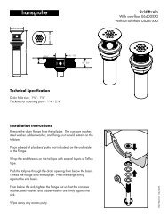
88 9001 002 CDrawer (P)Unit Part List* If you are missing any of theseparts, please contact our DMICustomer Service Departmentat 1-877-831-0319 or fax us at1-800-755-2878.HARDWARE LISTP1.Front Part1 pc.P3.Side Part1 pc.P4.Side Part1 pc.Pull Handle1 pc.Wood Screw(for Base)6 pcs.(+1 extra)P2.Back Part1 pc.P5.Base1 pc.Machine Screwfor Pull Handle2 pc.Wood Screw(for Side Part)8 pcs.(+1 extra)<strong>Assembly</strong> <strong>Instructions</strong>P3P2(Fig)1P1P4(Fig) 1Assemble the Front Part (P1), Back Part(P2) and Side Part (P3) and (P4).Using a Phillips screw driver, insert 1”screw into the pre-drilled holes at theside parts, tighten half way.(Fig) 2Slide the Plywood Base (P5) into the grooveson side parts. Be sure to push the Base all theway forward so it meets the Front Part.P3P1P5(Fig)2P4P3P1(Fig) 3(Fig)3P2P5P4Insert the remaining ½” screws (6 pcs.)into the pre-drilled holes at the Base,then tighten up all screws.(Fig) 4Assemble the Pull Handleto the Front Part withMachine Screw.(Fig)4