Installation and Assembly - Universal Articulating
Installation and Assembly - Universal Articulating
Installation and Assembly - Universal Articulating

Create successful ePaper yourself
Turn your PDF publications into a flip-book with our unique Google optimized e-Paper software.
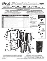
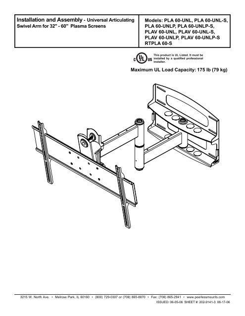
<strong>Installation</strong> <strong>and</strong> <strong>Assembly</strong> - <strong>Universal</strong> <strong>Articulating</strong>Swivel Arm for 32" - 60" Plasma ScreensModels: PLA 60-UNL, PLA 60-UNL-S,PLA 60-UNLP, PLA 60-UNLP-S,PLAV 60-UNL, PLAV 60-UNL-S,PLAV 60-UNLP, PLAV 60-UNLP-SRTPLA 60-SRThis product is UL Listed. It must beinstalled by a qualified professionalinstaller.Maximum UL Load Capacity: 175 lb (79 kg)3215 W. North Ave. • Melrose Park, IL 60160 • (800) 729-0307 or (708) 865-8870 • Fax: (708) 865-2941 • www.peerlessmounts.comISSUED: 06-05-06 SHEET #: 202-9141-3 08-17-06
Read instruction sheet before you start installation <strong>and</strong> assembly.WARNING• Do not begin to install your Peerless product until you have read <strong>and</strong> understood the instructions <strong>and</strong> warningscontained in this <strong>Installation</strong> Sheet. If you have any questions regarding any of the instructions or warnings, pleasecall Peerless customer care at 1-800-729-0307.• This product should only be installed by a qualified professional.• Make sure that the supporting surface will safely support the combined load of the equipment <strong>and</strong> all attached hardware<strong>and</strong> components.• Never exceed the Maximum UL Load Capacity of 175 lb (79 kg).• Never mount this product to metal studs.• If mounting to wood wall studs, make sure that mounting screws are anchored into the center of the studs. Use of an"edge to edge" stud finder is highly recommended.• Always use an assistant or mechanical lifting equipment to safely lift <strong>and</strong> position equipment.• Tighten screws <strong>and</strong> nuts firmly, but do not overtighten. Overtightening can damage the items, greatly reducing theirholding power.IMPORTANT! Certain types of walls require additional mounting hardware...WALL CONSTRUCTIONWood Stud, Wood BeamSolid ConcreteOther or unsure?ADDITIONAL HARDWARE REQUIREDnoneContact Customer Care for accessory kitContact Customer CareIMPORTANT! Turn to the appropriate page for your wall installation.<strong>Installation</strong>s:To Wood Stud Walls ...................................................................................................... page 6To Concrete Walls .......................................................................................................... page 7Accessories• concrete anchor 4-pack (ACC 224)Tools Needed for <strong>Assembly</strong>• stud finder ("edge to edge" stud finder is recommended)• drill• 7/32" drill bit for wood studs• 5/16" drill bit for concrete• 7/16" socket wrench with extension (recommended)• level• phillips screwdriver2 of 13 ISSUED: 06-05-06 SHEET #: 202-9141-3 08-17-06
Wall Mount Parts ListRTPLA 60-SBefore you start make sure all parts PLA 60-UNL PLA 60-UNL-S PLAV 60-UNL PLAV 60-UNL-Slisted are included with your product. PLA 60-UNLP PLA 60-UNLP-S PLAV 60-UNLP PLAV 60-UNLP-SDESCRIPTION QTY. PART # PART # PART # PART #A wall plate 1 201-1040 201-4040 201-1040 201-4040B tilt-roll assembly 1 201-1093 201-4093 201-1048 201-4048C arm assembly 1 201-1072 201-4072 201-1049 201-4049D wall support arm axle 1 201-1041 201-1041 201-1041 201-1041E vinyl trim 3 600-1012 600-1012 600-1012 600-1012F M10 x 1.5 x 15 mm screw bolt 8 520-9262 520-9262 520-9262 520-9262G .505 x .75 x .062" nylon washer 1 540-1074 540-1074 540-1074 540-1074H tilt adjustment knob 1 560-0108 560-0108 560-0108 560-0108I carriage bolt 3/8"-16 x 3.25" 1 520-1315 520-1315 520-1315 520-1315J 1.525 x 2 x .062" delrin washer 2 540-1070 540-1070 540-1070 540-1070K #8-32 x .375" socket cap screw 1 520-1210 520-1210 520-1210 520-1210L plastic finishing cap 8 590-1123 590-1123 590-1123 590-1123M holding pin 1 580-1166 580-1166 580-1166 580-1166N retainer plug 1 590-1007 590-1007 590-1007 590-1007O 5/16 x 3" wood screw 8 520-1243 520-1243 520-1243 520-1243P .250 x 1 x .068" washer 8 540-1063 540-1063 540-1063 540-1063Q 9/64" allen wrench 1 560-9728 560-9728 560-9728 560-9728R cable management clips 4 590-1166 590-1166 590-1166 590-1166S cable tie 4 590-1168 590-1168 590-1168 590-1168T 36" polyester mesh sleeve 1 600-1015 600-1015 600-1015 600-1015U 6 mm allen wrench 1 560-9716 560-9716 560-9716 560-9716V 10 mm allen wrench 1 n/a n/a 560-9727 560-9727DEFGHKJBLMNAQIVRCOSome parts may appear slightly different than illustrated.PUST3 of 13 ISSUED: 06-05-06 SHEET #: 202-9141-3 08-17-06
Before you begin, make sure all parts shown are included with your product.RTPLA 60-SPLA 60-UNL PLA 60-UNL-S PLA 60-UNLP PLA 60-UNLP-SAdapter Bracket Parts List PLAV 60-UNL PLAV 60-UNL-S PLAV 60-UNLP PLAV 60-UNLP-SDescription Qty Part # Part # Part # Part #AA adapter bracket 1 201-1110 201-4110 201-1110 201-4110BB shallow adapter bracket 2 200-0756 200-0757 200-0754 200-0755CC deep adapter bracket 2 200-0752 200-0753 200-0750 200-0751DD allen wrench 1 560-9646 560-9646 560-0072 560-0072BBCCAADD4 of 13 ISSUED: 06-05-06 SHEET #: 202-9141-3 08-17-06
Security Adapter Bracket FastenersM4 x 12 mm (6)510-1079M5 x 12 mm (4)520-1064M6 x 12 mm (4)520-1050M8 x 15 mm (6)520-1068M6 x 20 mm (4)520-9554M5 x 25 mm (4)520-1122M4 x 25 mm (4)510-1082M6 x 30 mm (4)520-1067M6 x 25 mm (4)520-1211M8 x 25 mm (4)520-1101M8 x 40 mm (4)520-1152multi-washer (6)580-1036I.D. 5.6 mm (4)540-1057I.D. 8.7 mm (4)540-1059Phillips Adapter Bracket FastenersM4 x 12 mm (6)504-9013M5 x 12 mm (4)520-1027M6 x 12 mm (4)520-1128M8 x 16 mm (6)520-9257M6 x 20 mm (4)520-9402M5 x 25 mm (4)520-9543M4 x 25 mm (4)504-1015M6 x 30 mm (4)510-9109M6 x 25 mm (4)520-1208M8 x 25 mm (4)520-1031M8 x 40 mm (4)520-1136multi-washer (6)580-1036I.D. 5.6 mm (4)540-1057I.D. 8.7 mm (4)540-10595 of 13 ISSUED: 06-05-06 SHEET #: 202-9141-3 08-17-06
<strong>Installation</strong> to Wood Stud WallWARNING• Installer must verify that the supporting surface will safely support the combined load of the equipment <strong>and</strong> all attachedhardware <strong>and</strong> components.• Tighten wood screws so that wall plate is firmly attached, but do not overtighten. Overtightening can damage thescrews, greatly reducing their holding power.• Never tighten in excess of 80 in. • lb (9 N.M.).• Never mount this product to metal studs.• Make sure that mounting screws are anchored into the center of the stud. The use of an "edge to edge" stud finder ishighly recommended.• Hardware provided is for attachment of mount through st<strong>and</strong>ard thickness drywall or plaster into wood studs. Installersare responsible to provide hardware for other types of mounting situations.• Never exceed the Maximum UL Load Capacity of 175 lb (79 kg).1Wall plate (A) can be mounted to two studs that are 16" apart. Use a stud finder to locate the edges of thestuds. Use of an edge-to-edge stud finder is highly recommended. Based on their edges, draw a vertical linedown each stud’s center. Place wall plate on wall as a template. The top mounting slots should be located .36"above the desired screen center for PLA 60-UNL, PLA 60-UNL-S, PLA 60-UNLP, PLA 60-UNLP-S <strong>and</strong> RTPLA 60-S <strong>and</strong> .43" below the desired screen center for PLAV 60-UNL, PLAV 60-UNL-S, PLAV 60-UNLP <strong>and</strong> PLAV 60-UNLP-S. Level plate, <strong>and</strong> mark the center of the eight mounting holes. Make sure that the mounting holes are onthe stud centerlines. Drill eight 7/32" dia. holes 3" deep. Make sure that the wall plate is level, secure it usingeight 5/16 x 3" wood screws (O) <strong>and</strong> washers (P).Skip to step 2 on page 8.OPA6 of 13 ISSUED: 06-05-06 SHEET #: 202-9141-3 08-17-06
<strong>Installation</strong> to Concrete WallWARNING• Concrete must be 2000 psi density minimum. Lighter density concrete may not hold concrete anchor.• Make sure that the supporting surface will safely support the combined load of the equipment <strong>and</strong> all attachedhardware <strong>and</strong> components.• Never exceed the Maximum UL Load Capacity of 175 lb (79 kg).• Never mount this product to metal studs.1IMPORTANT! Concrete must be 2000 psi density minimum.Note: Fasteners for concrete walls are not included,order TWO #ACC 224 accessory kits for installationon concrete walls.Use wall plate (A), making sure that it is level, as atemplate to mark holes. The top mounting slots shouldbe located .36" above the desired screen center for PLA60-UNL, PLA 60-UNL-S, PLA 60-UNLP, PLA 60-UNLP-S<strong>and</strong> RTPLA 60-S <strong>and</strong> .43" below the desired screencenter for PLAV 60-UNL, PLAV 60-UNL-S, PLAV 60-UNLP <strong>and</strong> PLAV 60-UNLP-S. Drill 5/16" (8 mm) dia.holes to a minimum depth of 3" (76 mm). Insert anchorsin holes flush with wall as shown (right). Place wall plate(A) over anchors <strong>and</strong> secure with 5/16 x 3" wood screws(O) <strong>and</strong> washers (P).1Drill hole(s) <strong>and</strong> insert anchor(s)2mountingplateconcretesurfaceconcreteanchorconcreteanchorWARNING• Tighten wood screws so that wall plate is firmlyattached, but do not overtighten. Overtightening c<strong>and</strong>amage screws, greatly reducing their holding power.• Never tighten in excess of 80 in • lb (9 N.M.).WARNING• Always attach concrete expansion anchors directly toload-bearing concrete.• Never attach concrete expansion anchors to concretecovered with plaster, drywall, or other finishing material.If mounting to concrete surfaces covered with afinishing surface is unavoidable, the finishing surfacemust be counterbored as shown below. If plaster/drywall is thicker than 5/8", custom fasteners must besupplied by installer (Not evaluated by UL).Place plate over anchor(s) <strong>and</strong> secure with screw(s)3Tighten all fastenersO PconcreteanchorINCORRECTCORRECTCUTAWAY VIEWmountingplateplaster/dry wallconcretemountingplateplaster/dry wallconcreteA7 of 13 ISSUED: 06-05-06 SHEET #: 202-9141-3 08-17-06
WARNING• If you are uncertain that product is properly installed, call customer care.22-1Note: There are five mounting positions. Thecenter position is shown (right). Slide washer (J)over wall support arm axle (D). Next, insert plasticcap (N) into axle. Then, insert holding pin (M) intoaxle. See detail 1.Place arm assembly (C) with washer (J) into wallplate (A). Insert axle assembly shown in detail 1through wall plate (A), arm assembly (C), <strong>and</strong>washer (J). Lock axle in place by aligning holdingpin (M) with notches shown in detail 2.ANJDMDETAIL 12-2Insert socket cap screw (K) into hole at bottom ofwall support arm axle (D) as shown in detail 3.Tighten screw using 9/64" allen wrench (Q).Note: Fit of axle (D) into wall plate (A) <strong>and</strong> armassembly (C) will be tight. Gently tap into placewith a hammer if necessary.CNOTCHDETAIL 2JKDDETAIL 333-1Snap four cable management clips (R) into top or bottom of arm assembly (C) as shown. Cable ties (S) are usedwith clips for cord management.Slide one mesh sleeve (T) over each cable. Use cable ties (S) to tighten mesh sleeves to cables.RTCS8 of 13 ISSUED: 06-05-06 SHEET #: 202-9141-3 08-17-06
44-1Attach two pieces of vinyl trim (E) to wall plate (A). Next, attach one piece of vinyl trim to bottom of swivel box on armassembly (C).Insert one finishing cap (L) into each unused hole of wall plate (A).LASWIVEL BOXCE5Insert <strong>and</strong> tape carriage bolt (I) into top hole of pitch-roll assembly (B). Attach tilt-roll assembly to adapterbracket (AA) with four M10 socket screws (F). Tighten screws using 6 mm allen wrench (U).CAUTION• Do not overtighten screws! Overtightening may hinderroll option.AAIBF9 of 13 ISSUED: 06-05-06 SHEET #: 202-9141-3 08-17-06
WARNING• Use an assistant or mechanical lifting equipment to safely lift <strong>and</strong> position the plasma TV.6Insert two M10 screws (F) into swivel box on arm assembly (C) as shown. Leave approx. 1/4" of exposed thread.SWIVEL BOXC.25"F6-16-2Hook tilt-roll assembly (B) onto M10 screws (F).Insert carriage bolt (I) into slot of swivel box asshown in figure 6.1. Install nylon washer (G) <strong>and</strong> tiltadjustment knob (H).Install remaining two M10 screws (F) as shown infigure 6.2. HAND TIGHTEN all four M10 screws toallow for tilt adjustment. Remove tape from carriagebolt (I). For tilt adjustment, push back on the top ofplasma to relieve pressure on knob. Adjust tilt todesired position <strong>and</strong> tighten tilt adjustment knob (H),then securely tighten all four M10 screws (F) using 6mm allen wrench (U).SWIVEL BOXIGHCAUTION• After tilt is adjusted, all fasteners must be tightened.Failure to do so will result in damage to the mount.IHFBFfig 6.1 fig 6.2Adapter bracket not shown for clarity.Adapter bracket not shown for clarity.10 of 13 ISSUED: 06-05-06 SHEET #: 202-9141-3 08-17-06
Installing Adapter Brackets7Refer to Screen Compatibility Chart to determine the proper fasteners to use.To prevent scratching the screen, set a cloth on a flat, level surface that will support the weight of the screen. Placescreen face side down. If screen has knobs on the back, remove them to allow the adapter brackets to be attached.Place adapter brackets (BB or CC) on back of screen, align to holes, <strong>and</strong> center on back of screen as shown in figure7.1. Attach the adapter brackets to the back of the screen using the appropriate combination of screws, multi-washers,<strong>and</strong> spacers as shown in figure 7.3.Note: Top <strong>and</strong> bottom holes must always be used.Verify that all holes are properly aligned, <strong>and</strong> then tighten screws using a phillips screwdriver.Note: If using security screws, tighten using security allen wrench (DD).WARNING• Tighten screws so adapter brackets are firmlyattached. Do not tighten with excessive force.Overtightening can cause stress damage to screws,greatly reducing their holding power <strong>and</strong> possiblycausing screw heads to become detached. Tighten to40 in. • lb (4.5 N.M.) maximum torque.BBorCCCENTER BRACKETSVERTICALLY ON BACK OFSCREENXNotes:• The number of fasteners used will vary,depending upon the type of screen.• Multi-washers <strong>and</strong> spacers may not beused, depending upon the type of screen.• Use the corresponding hole in the multiwasherthat matches your screw size asshown in figure 7.2.fig 7.1XNote: "X" dimensions should be equal.WARNING• If screws don't get three complete turns in the screeninserts or if screws bottom out <strong>and</strong> bracket is still nottightly secured, damage may occur to screen orproduct may fail.BB or CCSCREWSMULTI-WASHERMEDIUM HOLE FOR M5 SCREWSMULTI-WASHERSPACERSSMALL HOLE FOR M4 SCREWSLARGE HOLE FOR M6 SCREWSfig. 7.2fig 7.311 of 13 ISSUED: 06-05-06 SHEET #: 202-9141-3 08-17-06
Mounting <strong>and</strong> Removing Flat Panel Screen8Refer to mount instruction sheet for attachment of adapter bracket to mount.Hook adapter brackets (BB or CC) onto adapter bracket (AA), then slowly swing screen in as shown. Turn screwsclockwise at least six times to prevent screen from being removed as shown in detail 4. Tighten using allen wrench (DD).Screen can be adjusted horizontally if desired.Note: To lock the screen down, tighten screws to adapter bracket as shown in detail 4.To remove screen from mount, loosen screws, swing screen away from mount, <strong>and</strong> lift screen off of mount.WARNING• Always use an assistant or mechanical lifting equipment to safely lift <strong>and</strong> position the plasma television.BB or CCAASCREWSBBorCCAADETAIL 412 of 13 ISSUED: 06-05-06 SHEET #: 202-9141-3 08-17-06