I O & M Manual - BJM Pumps
I O & M Manual - BJM Pumps
I O & M Manual - BJM Pumps

You also want an ePaper? Increase the reach of your titles
YUMPU automatically turns print PDFs into web optimized ePapers that Google loves.
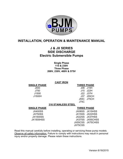
INSTALLATION, OPERATION & MAINTENANCE MANUALJ & JX SERIESSIDE DISCHARGEElectric Submersible <strong>Pumps</strong>Single Phase115 & 230VThree Phase208V, 230V, 460V & 575VUSINGLE PHASE UJ400J750J1500J1500HUSINGLE PHASE UJX400SSJX750SSJX1500SSJX1500HSSUCAST IRONUU316 STAINLESS STEEL UUTHREE PHASEUJ08 J15HJ15 J22HJ22 J37HJ37 J55CHJ55C J75CHJ75CUTHREE PHASEUJX08SSJX15SSJX22SSJX37SSJX55CSSJX75CSSJX15HSSJX22HSSJX37HSSJX55CHSSJX75CHSSRead this manual carefully before installing, operating or servicing these pump models.UObserve all safety information.U Failure to comply with instructions may result in personalinjury and/or property damage. Please retain these instructions.Version 6/18/2015
TABLE OF CONTENTSINTRODUCTION ............................................................................................................................................................................................. 4SAFETY .......................................................................................................................................................................................................... 5INSPECTION .................................................................................................................................................................................................. 6PRE-INSTALLATION INSPECTION ............................................................................................................................................................ 6OIL FILL QUANTITY/TYPE ......................................................................................................................................................................... 7PUMP INSTALLATION ............................................................................................................................................................................... 8POSITIONING THE PUMP ......................................................................................................................................................................... 8PUMP ROTATION ...................................................................................................................................................................................... 9PUMP OPERATION...................................................................................................................................................................................10TYPICAL MANUAL DEWATERING-EFFLUENT INSTALLATION ................................................................................................................. 10TYPICAL AUTOMATIC DEWATERING-EFFLUENT INSTALLATION ........................................................................................................... 11INTENDED METHODS OF CONNECTION ................................................................................................................................................... 12SINGLE PHASE WIRING INSTRUCTIONS ...............................................................................................................................................13THREE PHASE WIRING INSTRUCTIONS ................................................................................................................................................13TROUBLE SHOOTING ................................................................................................................................................................................. 14PUMP WILL NOT RUN ..............................................................................................................................................................................14PUMP RUNS BUT DOES NOT DELIVER RATED CAPACITY ........................................................................................................................ 5SERVICING YOUR SUBMERSIBLE PUMP ................................................................................................................................................ 5MAINTAINING YOUR PUMP ...................................................................................................................................................................... 5CHANGING SEAL OIL ................................................................................................................................................................................ 5EXPLODED VIEW OF J400, JX400SS.......................................................................................................................................................... 15EXPLODED VIEW OF J750, J1500, J1500H................................................................................................................................................. 16EXPLODED VIEW OF J08, J15, J15H .......................................................................................................................................................... 17EXPLODED VIEW OF J22, J22H, J37, J37H, ............................................................................................................................................... 18EXPLODED VIEW OF J55C, JX55CSS, J55CH, JX55CHSS, J75C, JX75CSS, J75CH, JX75CHSS ............................................................ 19EXPLODED VIEW OF JX750SS, JX1500SS, JX1500HSS (PRECISION CAST MODELS) ........................................................................... 20EXPLODED VIEW OF JX08SS, JX15SS, JX15HSS (PRECISION CAST MODELS) .................................................................................... 21EXPLODED VIEW OF JX22SS, JX37SS (PRECISION CAST MODELS) ...................................................................................................... 22J SERIES PARTS LIST ................................................................................................................................................................................. 23JX PRECISION CAST PARTS LIST .............................................................................................................................................................. 25SINGLE PHASE WIRING DIAGRAM 115V & 230V W/O GOVERNOR SWITCH........................................................................................... 27MODELS J400, JX400SS .....................................................................................................................................................................27MODELS J750, JX750, J1500, JX1500H, JX1500HSS .........................................................................................................................28THREE PHASE WIRING DIAGRAM ............................................................................................................................................................. 29208V ..........................................................................................................................................................................................................29MODELS J08, JX08SS, J15, JX15SS, J15H, JX15HSS, J22, JX22SS, J22H, JX22HSS, J37. JX37SS, J37H, J37HSS, J55C, J55CSS,J55CH, J55CHSS, J75C, JX75CSS, J75CH, J75CHSS ........................................................................................................................29230V ..........................................................................................................................................................................................................30MODELS J08, JX08SS, J15, JX15SS, J15H, JX15HSS, J22, JX22SS, J22H, JX22HSS, J37. JX37SS, J37H, J37HSS, J55C, J55CSS,J55CH, J55CHSS, J75C, JX75CSS, J75CH, J75CHSS ........................................................................................................................30460V ..........................................................................................................................................................................................................31MODELS J08, JX08SS, J15, JX15SS, J15H, JX15HSS, J22, JX22SS, J22H, JX22HSS, J37, JX37SS, J37H,J37HSS, J55C, J55CSS,J55CH, J55CHSS, J75C, JX75CSS, J75CH, J75CHSS ........................................................................................................................31575V ..........................................................................................................................................................................................................32MODELS J08, JX08SS, J15, JX15SS, J15H, JX15HSS, J22, JX22SS, J22H, JX22HSS, J37. JX37SS, J37H, J37HSS, J55C, J55CSS,J55CH, J55CHSS, J75C, JX75CSS, J75CH, J75CHSS ........................................................................................................................32SEAL MINDER® ........................................................................................................................................................................................... 33WARRANTY AND LIMITATION OF LIABILITY .............................................................................................................................................. 35START-UP REPORT FORM ......................................................................................................................................................................... 36NOTES:......................................................................................................................................................................................................... 39
INTRODUCTIONThis Installation, Operation and Maintenance manual provides important information on safetyand the proper inspection, disassembly, assembly and testing of the <strong>BJM</strong> <strong>Pumps</strong>® J & JXSeries submersible pump. This manual also contains information to optimize performance andlongevity of your <strong>BJM</strong> <strong>Pumps</strong> submersible pump.The submersible J Series pumps are designed to pump water and municipal/industrialeffluent wastewater. The JX Series pumps are designed to pump corrosive liquids inconcentrations chemically compatible with 316SS and FKM. The J & JX Series pumps arenot explosion proof. They are not designed to pump volatile or flammable liquids.Note: Consult chemical resistance chart for compatibility between pump materials andliquid before operating pump.If you have any questions regarding the inspection, disassembly, assembly or testing pleasecontact your <strong>BJM</strong> <strong>Pumps</strong> distributor, or <strong>BJM</strong> <strong>Pumps</strong>, LLC.<strong>BJM</strong> <strong>Pumps</strong>, LLC123 Spencer Plain Rd.Old Saybrook, CT 06475, USAFax: 860-399-7784Phone: 877-256-7867Phone: 860-399-5937Information, including pump data sheets and performance curves, is also available onour web site: HUwww.bjmpumps.comUFor assistance with your electric power source, please contact a certified electrician.Please pay attention to the following alert notifications. They are used to notifyoperators and maintenance personnel to pay special attention to procedures, to avoidcausing damage to the equipment, and to avoid situations that could be dangerous topersonnel.NOTE: Instructions to aid in installation, operation, and maintenance or whichclarify a procedure.Immediate hazards that WILL result in severe personal injury ordeath. These instructions describe the procedure required and the injury which willresult from failure to follow the procedure.Hazards or unsafe practices that COULD result in severe personalinjury or death. These instructions describe the procedure required, and the injury whichcould result from failure to follow the procedure.Hazards or unsafe practices which COULD result in personal injuryor product or property damage. These instructions describe the procedure required andthe possible damage which could result from failure to follow the procedure.4
SAFETYPump installations are seldom identical. Each installation and application can vary dueto many different factors. It is the owner/service mechanics responsibility to repair,service, and test to ensure that the pump integrity is not compromised according to thismanual.Risk of electric shock – this pump has not been investigated for usein swimming pool areas.Do not pump flammable, inflammable or volatile liquids. UDeathor serious injury will result.Before attempting to open or service the pump:1) Familiarize yourself with this manual.2) Unplug or disconnect the pump power cable to ensure that the pump will remaininoperative.3) Allow the pump to cool if overheated.Do not operate the pump with a worn or damaged electric powercable. Death or serious injury could occur.Never attempt to alter the length or repair any power cable with asplice. The pump motor and pump motor and cable must be completely waterproof.Damage to the pump or personal injury may result from alterations.After the pump has been installed, make sure that the pump and allpiping are secure before operation.Do not lift the pump by the power cable piping or discharge hose.Attach proper lifting equipment to the lifting handle (or lifting rings) fitted to the pump. Donot suspend the pump by the power cable.Obtain the services of a qualified electrician to troubleshoot, testand/or service the electrical components of this pump.<strong>Pumps</strong> and related equipment must be installed and operatedaccording to all national, local and industry standards.5
INSPECTIONReview all safety information before servicing pump.The following are recommended installation practices/procedures for the pump. If thereare questions in regards to your specific application, contact your local <strong>BJM</strong> <strong>Pumps</strong>distributor or <strong>BJM</strong> <strong>Pumps</strong>, LLC.PRE-INSTALLATION INSPECTION1) Check the pump for damage that may have occurred during shipment.2) Inspect the pump for any cracks, dents, damaged threads, etc.3) Check power cord (and Seal Minder® cord, if installed) for any cuts or damage.4) Check for, and tighten any hardware that appears loose.5) Carefully read all tags, decals and markings on the pump.If anything appears to be abnormal, contact your <strong>BJM</strong> <strong>Pumps</strong> distributor or <strong>BJM</strong><strong>Pumps</strong>, LLC. If damaged, the pump may need to be repaired before use. Do not installor use the pump until appropriate action has been taken.Lubrication:No additional lubrication is necessary. The shaft seal and bearings are fully lubricatedfrom the factory. Seal oil should be checked once per year. See table below.6
Note: For EPDM seals propylene glycol is used in the seal chamberOIL FILL QUANTITY/TYPEQty. oil in seal chamberModels U.S. fl. oz. C.C. Type of oilJ400 5.1 150 ISO 32 NSF Food Mineral GradeJ750 9 265 ISO 32 NSF Food Mineral GradeJ1500 9 265 ISO 32 NSF Food Mineral GradeJ08 9 265 ISO 32 NSF Food Mineral GradeJ15 9 265 ISO 32 NSF Food Mineral GradeJ22 10.8 320 ISO 32 NSF Food Mineral GradeJ37 10.8 320 ISO 32 NSF Food Mineral GradeJ55C 45.6 1350 ISO 32 NSF Food Mineral GradeJ75C 45.6 1350 ISO 32 NSF Food Mineral GradeQty. oil in seal chamberModels U.S. fl. oz. C.C. U.S. fl. oz.J1500H 9 265 ISO 32 NSF Food Mineral GradeJ15H 9 265 ISO 32 NSF Food Mineral GradeJ22H 10.8 320 ISO 32 NSF Food Mineral GradeJ37H 10.8 320 ISO 32 NSF Food Mineral GradeJ55CH 45.6 1350 ISO 32 NSF Food Mineral GradeJ75CH 45.6 1350 ISO 32 NSF Food Mineral GradeQty. oil in seal chamberModels U.S. fl. oz. C.C. Type of oilJX400SS 5.1 150 ISO 32 NSF Food Mineral GradeJX750SS 10.1 300 ISO 32 NSF Food Mineral GradeJX1500SS 10.1 300 ISO 32 NSF Food Mineral GradeJX08SS 10.1 300 ISO 32 NSF Food Mineral GradeJX15SS 10.1 300 ISO 32 NSF Food Mineral GradeJX22SS 13.5 400 ISO 32 NSF Food Mineral GradeJX37SS 13.5 400 ISO 32 NSF Food Mineral GradeJX55CSS 45.6 1350 ISO 32 NSF Food Mineral GradeJX75CSS 45.6 1350 ISO 32 NSF Food Mineral GradeQty. oil in seal chamberModels U.S. fl. oz. C.C. Type of oilJX1500HSS 10.1 300 ISO 32 NSF Food Mineral GradeJX15HSS 10.1 300 ISO 32 NSF Food Mineral GradeJX22HSS 13.5 400 ISO 32 NSF Food Mineral GradeJX37HSS 13.5 400 ISO 32 NSF Food Mineral GradeJX55CHSS 45.6 1350 ISO 32 NSF Food Mineral GradeJX75CHSS 45.6 1350 ISO 32 NSF Food Mineral Grade7
PUMP INSTALLATIONJ & JX Series pumps have been evaluated for use with water or water based solutions.Please contact the manufacturer for additional information.Risk of electric shock. Pump models; J400, JX400, J750 &JX750 (115v) are supplied with a grounding conductor and grounding-type attachmentplug. Pump models 230V single phase pumps and all three phase pumps do not comewith electric plug connectors. To reduce the risk of electric shock, be certain that it isconnected only to a properly grounded, grounding-type receptacle.Lifting:Attach a rope or lifting chain (not included) to the handle (or lifting rings) on the top ofthe pump.Do not lift the pump by the power cable or discharge hose/piping.Proper lifting equipment (rope/chain) must be used.POSITIONING THE PUMP<strong>BJM</strong> <strong>Pumps</strong>, J & JX Series pumps are designed to operate fully or partially submerged.Do not run the pump dry. Refer to data sheet for minimum submersion depth for yourparticular model. Data sheets can be obtained online at HUwww.bjmpumps.comUH or bycalling <strong>BJM</strong> <strong>Pumps</strong>, LLC at 860-399-5937. As a general rule, J and JX Series sidedischarge pumps can pump down to a level above the suction screen. Pumping lowerthan screen will permit air to enter the pump and cavitate, lose prime or become airbound.Do not run the pump dry.Pump liquid should not exceed a maximum temperature of 104°F.Never place the pump on loose or soft ground. The pump may sink, preventingwater from reaching the impeller. Place on a solid surface or suspend the pumpwith a lifting rope/chain. The J & JX Series pumps are provided with a suctionstrainer to prevent large solids from clogging the impeller. Any spherical solidswhich pass through the strainer should pass through the pump.For maximum pumping capacity, use the proper size non-collapsible hose or rigidpiping. A check valve may be installed after the discharge to prevent back flowwhen the pump is shut off.8
PUMP ROTATIONTwo ways to check the correct pump rotation:1. By looking at the impeller; the rotation of the impeller should be counterclockwise as shown in the picture below.2. By looking from the top of the pump. Since the impeller cannot be seen, the bestway to check the rotation is to check the kick back motion of the pump when thepump just starts. The kick back motion of the pump should be counter clockwiseas shown in the picture below.9
PUMP OPERATIONThis pump is designed to handle dirty water that contains somesolids. It is not designed to pump volatile or flammable liquids. Do not attempt to pumpany liquids which may damage the pump or endanger personnel as a result of pumpfailure.Do not operate this pump where explosive vapors orflammable material exist. Death or Serious injury will result.TYPICAL MANUAL DEWATERING-EFFLUENT INSTALLATIONNOTE: Maximum recommended starts should not exceed 10 times per hour.All J & JX models are provided with a 33” (10m) power cord (exception; J1500, JX1500,J1500H) are supplied with a 50’ (15m) power cord. UNEVERU splice the power cable dueto safety and warranty considerations. Always keep the plug end dry.Note: 230V, single phase and 208V, 230V, 460V & 575V three phase units do nothave a plug and have to be provided separately.Do not alter the length or repair any power cable with a splice. Thepump motor and cable must be completely waterproof. Damage to the pump orpersonal injury may result from alterations.For manual operation: 115 volt: plug the power cable into any 115 volt groundedreceptacle. 208, 230, 460 & 575 volt: Attach the proper plug, connect directly to thepower source or control box. Check the direction of the rotation. Tilt the pump and startit. It should twist in the opposite direction of the arrow (on pump). It is recommendedthat a Ground Fault Interrupter (GFI) type receptacle (or equivalent) be used.10
Single phase pumps always use a three-prong groundedreceptacle. It is recommended that a Ground Fault Interrupter (GFI) type receptacle (orequivalent) be used.STOPPINGTo stop the pump (manual and automatic mode), unplug it from the power source, turnoff the breaker, or turn the power source off (generator).TYPICAL AUTOMATIC DEWATERING-EFFLUENT INSTALLATIONNOTE: Maximum recommended starts should not exceed 10 times per hour.Float switches (wired into the pump motor or piggy-back style) are available from thefactory as an option.Note: 208, 230V 460V & 575V pumps do not have a plug installed.Three phase pumps need a separate control box with float(s) for automaticoperation.11
STOPPINGTo stop the pump (manual and automatic mode), unplug it from the power source, turnoff the breaker, or turn the power source off(generator).Typical 3 phase manual control 1INTENDED METHODS OF CONNECTIONUse with approved motor control that matches motor input in fullload amperes. “UTILLISER UN DÉMARREAR APPROUVÉ CONVENANT AUCOURANT Á PLEINE CHARGE DU MOTEUR.”<strong>BJM</strong> <strong>Pumps</strong> has been evaluated for use with water or water based solutions. Pleasecontact the manufacturer for additional information.12
SINGLE PHASE WIRING INSTRUCTIONSFOR YOUR PROTECTION, ALWAYS DISCONNECT PUMPFROM ITS POWER SOURCE BEFORE HANDLING. Single phase pumps are suppliedwith a three prong grounded plug to help protect you against the possibility of electricalshock. DO NOT UNDER ANY CIRCUMSTANCES REMOVE THE GROUND PIN. Thethree prong plug must be inserted into a mating three prong grounded receptacle. IFthe installation does not have such a receptacle it must be changed to the proper type,wired and grounded in accordance with the National Electrical Code and all applicablelocal codes and ordinances“Risk of electrical shock” Do not remove power supply cord andstrain relief or connect conduit directly to the pump.Installation and checking of electrical circuits and hardware shouldbe performed by a qualified licensed electrician.THREE PHASE WIRING INSTRUCTIONSFOR YOUR PROTECTION, ALWAYS DISCONNECT PUMPFROM ITS POWER SOURCE BEFORE HANDLING.Typical 3 phase Auto Control 113
For“Risk of electrical shock” Do not remove power supply cord andstrain relief or connect conduit directly to the pump.Installation and checking of electrical circuits and hardware shouldbe performed by a qualified licensed electrician.To automatically operate a non-automatic three phase pump, a control panel isrequired. UFollow the instructions provided with the panel to wire the system. Uautomatic three phase pumps see automatic three phase wiring diagram.Before installing a pump, check the pump rotation to insure that wiring has beenconnected properly to power source, and that the green lead of power cord (See wiringdiagram), is connected to a valid ground, momentarily energize the pump, observing thedirections of kick back due to starting torque. Rotation is correct if kick back is in theopposite direction of rotation arrow on the pump casing. If rotation is not correct,switching of any two power leads other than ground will provide the proper rotation.Three phase pumps have integral motor overload protection. It is recommended that allthree phase pumps using a motor starting device also incorporate motor overloadprotection. <strong>Pumps</strong> must be installed in accordance with the National Electrical Codeand all applicable local codes and ordinances. <strong>Pumps</strong> are not to be installed in locationsclassified as hazardous in accordance with National Electrical Code, ANSI/NFPA 70.Connect pump to a junction box, outlet box, control box, enclosure with a wiringcompartment that meets NEC and local electrical codes. The provision for supplyconnection shall reduce the risk of water entry during temporary, limited submersionand shall comply with the applicable requirements of the Standard for Enclosures forElectrical Equipment, UL 50, or the standard for Metallic Outlet Boxes, UL 514A, andthe standard for Motor-Operated Water <strong>Pumps</strong>. UL 778.TROUBLE SHOOTINGDisconnect the power source to the pump BEFORE attemptingany type of trouble shooting, service or repair.PUMP WILL NOT RUN1. Check power supply (fuses, breaker).Reset power.2. Blocked impeller. Remove strainer,check and clean.3. Defective cable or incorrect wiring.4. Strainer clogged. Check and clean asnecessary.5. Float switch tangled/obstructed.Clean and free float switch fromobstruction.6. Float switch defective. Replace floatswitch.7. Pump overheated or temperature ofliquid exceeds pump operatingtemperature.14
UWarning: Pump will restart automatically when motor over-heat protection switchcools.PUMP RUNS BUT DOES NOT DELIVER RATED CAPACITY1. Discharge line clogged, restricted orhose kinked. Check dischargehose/pipe.2. Worn impeller and/or suction cover.Inspect and replace as necessary.3. Pump overloaded due to liquid pumpedbeing too thick.4. Pumping air. Check liquid level andposition of pump.5. Excessive voltage drops due to longcables.6. Three phase only; pump runningbackwards, check rotation.SERVICING YOUR SUBMERSIBLE PUMPPump should be disconnected from the electric power supply before proceeding to doany service or maintenance.To service or repair your pump, please contact your local <strong>BJM</strong> <strong>Pumps</strong> distributor.Service should only be performed by a qualified electrician.MAINTAINING YOUR PUMPPump should be disconnected from the electric power supply before proceeding todo any service or maintenance.Pump should be inspected at regular intervals.More frequent inspections are required if the pump is used in a harsh environment.Preventative maintenance should be performed to reduce the chance of prematurefailure.Worn impellers and lip seals should be replaced.Cut or cracked power cords must be replaced. (Never operate a pump with a cut,cracked or damaged power cord.)Seal oil should be checked once per year.Maintenance should always be done when taking a pump out of service beforestorage.1) Clean pump of dirt and other build up.2) Check condition of oil around the shaft seals.3) Check hydraulic parts: check for wear.4) Inspect power cable. Make sure that it is free of nicks or cuts.CHANGING SEAL OILChanging the seal oil in the J & JX Series pumps is very easy.1) Make sure that the pump cable isdisconnected from the power source.2) Lay the pump down on its side.3) Remove the screws that hold thebottom plate in place.4) Remove bottom plate.5) Remove screws holding the suctioncover.6) Remove the suction cover.7) Remove the impeller.5
8) Remove the inspection screw for the oilchamber (pos#50-08). Pour out a smallsample of the oil. If it is milky white, orcontains water, then the oil andpossible, the mechanical seal, shouldbe changed. If an oil change is needed:9) Remove the screws that hold the oilchamber cover in place & remove theoil.10) Replace the mechanical seal ifnecessary.11) Replace the oil.12) Assemble the pump.5
EXPLODED VIEW OF J400, JX400SS15
EXPLODED VIEW OF J750, J1500, J1500H16
EXPLODED VIEW OF J08, J15, J15H17
EXPLODED VIEW OF J22, J22H, J37, J37H18
EXPLODED VIEW OF J55C, JX55CSS, J55CH, JX55CHSS, J75C, JX75CSS, J75CH,JX75CHSS19
EXPLODED VIEW OF JX750SS, JX1500SS, JX1500HSS (PRECISION CASTMODELS)20
EXPLODED VIEW OF JX08SS, JX15SS, JX15HSS (PRECISION CAST MODELS)21
EXPLODED VIEW OF JX22SS, JX37SS (PRECISION CAST MODELS)22
J SERIES PARTS LISTPump Model J150 J400 J750 J1500 J1500H J08 J15 J15H J22 J22H J37 J37H J55C J55CH J75C J75CHPos. No. Part Description Item # Item # Item # Item # Item # Item # Item # Item # Item # Item # Item # Item # Item # Item # Item # Item #01 Strainer with Bottom Plate 201979 201964 - - - - - - 201973 201973 201973 201973 201976 201976 201976 20197601 Strainer - - 201969 201969 201969 201969 201969 201969 - - - - - - - -01-2 Bottom Plate - - 202007 202007 202007 202007 202007 202007 - - - - - - - -02 Suction Cover - - 202026 202026 202026 202026 202026 202026 202009 202011 202009 202011 202031 202032 202031 20203203 Impeller Nut 202890 - - - - 202894 202894 202894 202894 202894 202894 202894 202895 202895 202895 20289504 Lock washer - - - - - 202907 202907 202907 202907 202907 202907 202907 202904 202904 202904 20290405 Impeller 202921 202055 202930 202062 202064 202933 202067 202069 202937 202072 202074 202076 202078 202079 202082 20208306 Impeller Key - - - - - 202140 202140 202140 202140 202140 202140 202140 202141 202141 202141 20214107 Pump Housing 202988 202993 202163 202165 202163 202163 202165 202163 202167 202167 202167 202167 203007 203007 203007 20300707 -1 O-Ring (Kit Only) Kit Kit Kit Kit Kit Kit Kit Kit Kit Kit Kit Kit Kit Kit Kit Kit08 Oil Chamber Cover 202207 202207 202211 202211 202211 202211 202211 202211 202211 202211 202211 202211 203043 203043 203043 20304308 -1 O-Ring (Kit Only) Kit Kit Kit Kit Kit Kit Kit Kit Kit Kit Kit Kit Kit Kit Kit Kit09 Lip Seal Buna-N 202229 202229 202231 202231 202231 202231 202231 202231 202231 202231 202231 202231 203055 203055 203055 20305509 Lip Seal FKM (Optional) 202230 202230 202233 202233 202233 202233 202233 202233 202233 202233 202233 202233 203058 203058 203058 20305809 Lip Seal EPDM (Optional) 203050 203050 203053 203053 203053 203053 203053 203053 203053 203053 203053 203053 203056 203056 203056 20305609A Double Lip Seal Buna-N - - - - - - - - - - - - 202249 202249 202249 20224909A Double Lip Seal FKM (Optional) - - - - - - - - - - - - 202240 202240 202240 20224009A Double Lip Seal EPDM (Optional) - - - - - - - - - - - - 203060 203060 203060 20306010 Shaft Sleeve 202258 202258 - - - - - - - - - - 202256 202256 202256 20225610-1 O-Ring (Kit Only) - - - - - - - - - - - - Kit Kit Kit Kit10-2 O-Ring (Kit Only) - - - - - - - - - - - - Kit Kit Kit Kit12 Lip Seal for Lower Bearing - - - - - - - - - - - - 202236 202236 202236 20223613 Mechanical Seal Buna-N 202269 202259 200501 200501 200501 200501 200501 200501 200501 200501 200501 200501 200305 200305 200305 20030513 Mechanical Seal FKM** - 202260 200500 200500 200500 200500 200500 200500 200500 200500 200500 200500 200304 200304 200304 20030414 Lower Ball Bearing 200957 200493 200958 200958 200958 200958 200958 200958 200959 200959 200959 200959 200960 200960 200961 20096114-1 Lower Ball Bearing - - - - - - - - - - - - 200960 200960 200961 20096114-2 Lower Bearing Retainer Clip - - - - - - - - - - - - 202279 202279 202279 20227915 Impeller Shim Kit - - 200481 200481 200480 200480 200480 200480 200480 200480 200480 200480 200479 200479 200479 20047917 Rotor w/ Shaft 115/230V, 1PH 202299 202302 203086 203091 203091 - - - - - - - - - - -17 Rotor w/ Shaft, 3 PH - - - - - 202306 202310 202310 202314 202314 202318 202318 202343 202343 202345 20234518 Stator w/Casing,115V, 1PH - 200509 200511 - - - - - - - - - - - - -18 Stator w/Casing, 230V, 1PH - 200521 200570 200514 200514 - - - - - - - - - - -18 Stator w/Casing, 208V, 3PH - - - - - 200524 200528 200528 200532 200532 200536 200536 200665 200665 - -18 Stator w/Casing, 230V, 3PH - - - - - 200546 200550 200550 200554 200554 200558 200558 200562 200562 200566 20056618 Stator w/Casing, 460V, 3PH - - - - - - - - - - - - - - 200566 20056618 Stator w/Casing, 575V, 3PH - - - - - 200588 200592 200592 200596 200596 200600 200600 200605 200605 200609 20060919 Governor Switch w/Switch Plate - 202359 202360 202360 202360 - - - - - - - - - - -20 Upper Ball Bearing 200966 200957 200967 200967 200967 200967 200967 200967 200958 200958 200958 200958 200959 200959 200959 20095920-1 O-Ring (Kit Only) - - - - - - - - - - - - Kit Kit Kit Kit21A Oil Chamber 202990 200498 - - - - - - - - - - 202178 202178 202169 20216921A-1 O-Ring (Kit Only) Kit Kit - - - - - - - - - - Kit Kit Kit Kit21B Motor Cover - 202365 202368 202368 202368 - - - - - - - - - - -22 Cover Plate Upper - 202380 - - - - - - - - - - - - - -23 Overload 115V, 1PH - - 202383 - - - - - - - - - - - - -23 Overload 230V, 1PH - - 202395 202383 202383 - - - - - - - - - - -23 Overload 208V, 3PH - - - - - 202385 202388 202388 202390 202390 202392 202392 202394 202394 - -23 Overload 230V, 3PH - - - - - 202385 202388 202388 202390 202390 202392 202392 202394 202394 202396 20239623
23 Overload 460V, 3PH - - - - - 202387 202386 202386 202389 202389 202391 202391 202393 202393 202394 20239423 Overload 575V, 3PH - - - - - 202399 202387 202387 202386 202386 202389 202389 202391 202391 202393 20239324 Capacitor 115V 202414 202415 202417 - - - - - - - - - - - - -24 Capacitor 230V - 202416 202418 202420 202420 - - - - - - - - - - -26 Pump Top Cover 203119 203120 202433 202433 202433 202435 202435 202435 202445 202445 202445 202445 202439 202439 202439 20243926-1 O-Ring (Kit Only) Kit Kit Kit Kit Kit Kit Kit Kit Kit Kit Kit Kit Kit Kit Kit Kit27 Power Cable w/ Gland-115V, 1PH 201682 204257 204258 - - - - - - - - - - -27 Power Cable w/ Gland-230V, 1PH, No Plug 201684 201694 204260 204260 - - - - - - - - - - -27 Power Cable w/ Gland- 3PH - - - - - 201701 201701 201701 203442 203442 203444 203444 203446 203446 203446 20344627-1 O-Ring (Kit Only) Kit Kit Kit Kit Kit Kit Kit Kit Kit Kit Kit Kit Kit Kit Kit Kit27-2 Seal Minder Cable - - 202763 202764 202764 202763 202763 202763 202763 202763 202763 202763 202763 202763 202763 20276327-2-1 O-Ring (Kit Only) - - Kit Kit Kit Kit Kit Kit Kit Kit Kit Kit Kit Kit Kit Kit27-3 Oil Sensor Cap - - 203139 203139 203139 203139 203139 203139 203139 203139 203139 203139 203139 203139 203139 20313931D Seal Minder Probe - - 202409 202409 202409 202409 202409 202409 203998 203998 203998 203998 204000 204000 204000 20400031E Ground Wire w/Ring Term. 203145 203145 203145 203145 203145 203145 203145 203145 203145 203145 203145 203145 203145 203145 203145 20314532 Power Cord Line Clip / Strain Relief - 203161 203161 203161 203161 203161 203161 203161 204161 204161 202497 202497 202497 202497 202497 20249733 Seal Minder Cable Line Clip - - 203163 203163 203163 203163 203163 203163 203163 203163 203163 203163 203163 203163 203163 20316334 Handle 203167 202517 202517 202517 202517 202517 202517 202517 202517 202517 202517 202517 203171 203171 203171 20317135 Holding Rods - 202665 202666 202668 202668 202669 202670 202670 202671 202671 202672 202672 202673 202673 202674 20267438 Discharge Nipple - 202531 202531 202534 202531 202531 202534 202531 202534 202531 202534 202531 - - - -38E Discharge Elbow - - - - - - - - - - - - 202560 202560 202560 20256038E-1 Gasket Discharge Elbow Buna-N - - - - - - - - - - - - 203210 203210 203210 20321038E-1 Gasket Discharge Elbow FKM (Optional) - - - - - - - - - - - - 203211 203211 203211 20321138F Discharge Flange - - - - - - - - 202545 202543 202545 202543 202537 202538 202537 20253738F Discharge Connection 4" FNPT - - - - - - - - 202552 - 202552 - - - - -38F-1 Gasket -Discharge Flange Buna-N - - - - - - - - 202659 202659 202659 202659 203210 203210 203210 20321038F-1 Gasket - Discharge Flange FKM (Optional) - - - - - - - - 202660 202660 202660 202660 203211 203211 203211 20321150-01 Bolt - Strainer/Stand 203233 202694 203238 203238 203238 203238 203238 203238 203231 203231 203231 203231 203229 203229 203229 20322950-02 Screw - - 203216 203216 203216 203216 203216 203216 203228 203228 203228 203228 203229 203229 203229 20322950-07 Screw 203217 203216 - - - - - - - - - - 203229 203229 203229 20322950-08 Screw 203233 203215 203219 203219 203219 203219 203219 203219 203219 203219 203219 203219 203246 203246 203246 20324650-11 Screw 203218 203218 203218 203218 203218 203218 203218 203218 203218 203218 203218 203218 203218 203218 203218 20321850-11-1 O-Ring (Kit Only) Kit Kit Kit Kit Kit Kit Kit Kit Kit Kit Kit Kit Kit Kit Kit Kit50-12 Screw - 203218 203218 203218 203218 203218 203218 203218 203218 203218 203218 203218 203218 203218 203218 20321850-12-1 O-Ring (Kit Only) - Kit Kit Kit Kit Kit Kit Kit Kit Kit Kit Kit Kit Kit Kit Kit50-14-2 Screw - - - - - - - - - - - - 203219 203219 203219 20321950-19A Screw - 203215 - - - - - - - - - - - - - -50-19 Screw - 202693 202693 202693 202693 - - - - - - - - - - -50-21A Screw 202702 - - - - - - - - - - - - - - -50-22 Screw - 202692 - - - - - - - - - - - - - -50-23 Screw - - 202700 202700 202700 202700 202700 202700 202700 202700 202700 202700 202700 202700 202700 20270050-26 Acorn Nut and Washer 202701 - - - - - - - - - - - - - - -50-27 Screw 203232 203216 203216 203216 203216 203216 203216 203216 203246 203246 203246 203246 203246 203246 203246 20324650-27-2 Screw for Seal Minder Cable - - 203216 203216 203216 203216 203216 203216 203216 203216 203216 203216 203216 203216 203216 20321650-31E Screw 202692 202692 202692 202692 202692 202692 202692 202692 202692 202692 202692 202692 202692 202692 202692 20269250-32 Screw - 203214 203214 203214 203214 203214 203214 203214 - - - - - - - -50-33 Screw - 203214 203214 203214 203214 203214 203214 203214 203214 203214 203214 203214 - - - -50-34 Screw - 203219 203219 203219 203219 203219 203219 203219 203219 203219 203219 203219 - - - -50-34-1 Screw for Handle w/ Cable Chain - - - - - - - - - - - - 203228 203228 203228 20322850-34-2 Screw for Handle - - - - - - - - - - - - 203288 203288 203288 20328850-34-3 Lock Washer - - - - - - - - - - - - 202902 202902 202902 20290250-38E Bolt - Discharge Elbow - - - - - - - - - - - - 203287 203287 203287 20328750-38F Bolt - Discharge Flange - - - - - - - - 203253 203253 203253 203253 203287 203287 203287 20328724
JX PRECISION CAST PARTS LISTPump Model JX400SS JX750SS JX1500SS JX1500HSS JX08SS JX15SS JX15HSS JX22SS JX22HSS JX37SS JX37HSS JX55CSS JX55CHSS JX75CSS JX75CHSSPos. No. Part Description Item # Item # Item # Item # Item # Item # Item # Item # Item # Item # Item # Item # Item # Item # Item #01 Strainer with Bottom Plate 201965 201971 201971 201971 201971 201971 201971 201974 201974 201974 201974 201977 201977 201977 20197702 Suction Cover - 202027 202028 202027 202027 202028 202027 202010 202012 202010 202012 202034 202033 202034 20203303 Impeller Nut - - - - 202894 202894 202894 202894 202894 202894 202894 202895 202895 202895 20289504 Lock washer - - - - 202907 202907 202907 202907 202907 202907 202907 202904 202904 202904 20290405 Impeller 202056 202060 202063 202065 202066 202068 202070 202071 202073 202075 202077 202081 202080 202085 20208406 Impeller Key - - - - 202140 202140 202140 202140 202140 202140 202140 202141 202141 202141 20214107 Pump Housing 202994 202164 202166 202164 202164 202166 202164 202168 202168 202168 202168 202171 202171 202171 20217107 -1 O-Ring (Kit Only) Kit Kit Kit Kit Kit Kit Kit Kit Kit Kit Kit Kit Kit Kit Kit08 Oil Chamber Cover 202208 202214 202214 202214 202214 202214 202214 202219 202219 202219 202219 202216 202216 202216 20221608 -1 O-Ring (Kit Only) Kit Kit Kit Kit Kit Kit Kit Kit Kit Kit Kit Kit Kit Kit Kit09 Lip Seal FKM 202230 202232 202232 202232 202232 202232 202232 202235 202235 202235 202235 203058 203058 203058 20305809 Lip Seal Buna-N (Optional) 202229 203051 203051 203051 203051 203051 203051 202234 202234 202234 202234 203055 203055 203055 20305509 Lip Seal EPDM (Optional) 203050 203056 203056 203056 20305609A Double Lip Seal FKM - - - - - - - - - - - 202240 202240 202240 20224009A Double Lip Seal Buna-N (Optional) - - - - - - - - - - - 202249 202249 202249 20224909A Double Lip Seal EPDM (Optional) - - - - - - - - - - - 203060 203060 203060 20306010 Shaft Sleeve 202258 202257 202257 202257 20225712 Lip Seal for Lower Bearing - - - - - - - - - - - 202236 202236 202236 20223613 Mechanical Seal FKM** 202260 204240 204240 204240 204240 204240 204240 204243 204243 204243 204243 200304 200304 200304 20030413 Mechanical Seal Buna-N 202259 200501 200501 200501 200501 200501 200501 200302 200302 200302 200302 200305 200305 200305 20030514 Lower Ball Bearing 200493 200958 200958 200958 200958 200958 200958 200959 200959 200959 200959 200960 200960 200961 20096114-1 Lower Ball Bearing - - - - - - - - - - - 200960 200960 200961 20096114-2 Lower Bearing Retainer Clip - 202279 202279 202279 202279 202279 202279 202279 202279 202279 202279 202279 202279 202279 20227915 Impeller Shim Kit - 200481 200480 200480 200480 200480 200480 200480 200480 200480 200480 200479 200479 200479 20047917 Rotor w/ Shaft 115/230V, 1PH 202303 203089 203093 203093 - - - - - - - - - - -17 Rotor w/ Shaft, 3 PH - - - - 202308 202312 202312 202316 202316 202320 202320 202344 202344 202346 20234618 Stator w/Casing, 115V, 1HP 200510 200513 - - - - - - - - - - - - -18 Stator w/Casing, 230V, 1PH 200522 200571 200516 200516 - - - - - - - - - - -18 Stator w/Casing, 208V, 3PH - - - - 200526 200530 200530 200534 200534 200538 200538 200667 200667 - -18 Stator w/Casing, 230V,3PH - - - - 200548 200552 200552 200556 200556 200560 200560 200564 200564 - -18 Stator w/Casing, 460V, 3PH - - - - - - - - - - - - - 200568 20056818 Stator w/Casing, 575V, 3PH - - - - 200590 200594 200594 200598 200598 200602 200602 200607 200607 200611 20061119 Governor Switch w/Switch Plate 202359 202360 202360 202360 - - - - - - - - - - -20 Upper Ball Bearing 200957 200967 200967 200967 200967 200967 200967 200958 200958 200958 200958 200959 200959 200959 20095920-1 O-Ring (Kit Only) - - - - - - - - - - - Kit Kit Kit Kit21A Oil Chamber 200497 202197 202197 202197 202197 202197 202197 202198 202198 202198 202198 202179 202179 202170 20217021A-1 O-Ring (Kit Only) Kit Kit Kit Kit Kit Kit Kit Kit Kit Kit Kit Kit Kit Kit Kit21B Motor Cover 202365 202368 202368 202368 - - - - - - - - - - -22 Cover Plate Upper 202380 - - - - - - - - - - - - - -23 Overload 115V, 1PH - 202383 - - - - - - - - - - - - -23 Overload 230V, 1PH - 202395 202383 202383 - - - - - - - - - - -23 Overload 208V, 3PH - - - - 202385 202388 202388 202390 202390 202392 202392 202394 202394 - -23 Overload 230V,3PH - - - - 202385 202388 202388 202390 202390 202392 202392 202394 202394 - -25
23 Overload 460V,3PH - - - - 202387 202386 202386 202389 202389 202391 202391 202393 202393 202394 20239423 Overload 575V, 3PH - - - - 202399 202387 202387 202386 202386 202389 202389 202391 202391 202393 20239324 Capacitor 115V 202415 202417 - - 202818 - - - - - - - - - -24 Capacitor 230V 202416 202418 202420 202420 - - - - - - - - - - -26 Pump Top Cover 203121 202434 202434 202434 202436 202436 202436 202438 202438 202438 202438 202440 202440 202440 20244026-1 O-Ring (Kit Only) Kit Kit Kit Kit Kit Kit Kit Kit Kit Kit Kit Kit Kit Kit Kit27 Power Cable w/ Gland-115V, 1PH 204261 204262 - - - - - - - - - - - - -27 Power Cable w/ Gland-230V, 1PH, No Plug 201685 201695 201691 201691 - - - - - - - - - - -27 Power Cable w/ Gland- 3PH - - - - 201702 201702 201702 203443 203443 203445 203445 203447 203447 203447 20344727-1 O-Ring (Kit Only) Kit Kit Kit Kit Kit Kit Kit Kit Kit Kit Kit Kit Kit Kit Kit27-2 Seal Minder Cable - 201713 201716 20716 201713 201713 201713 201713 201713 201713 201713 201713 201713 201713 20171327-2-1 O-Ring (Kit Only) - Kit Kit Kit Kit Kit Kit Kit Kit Kit Kit Kit Kit Kit Kit27-3 Oil Sensor Cap - 201718 201718 201718 201718 201718 201718 201718 201718 201718 201718 201718 201718 201718 20171831D Seal Minder Probe - 202408 202408 202408 202408 202408 202408 202410 202410 202410 202410 204000 204000 204000 20400031E Ground Wire w/Ring Term. 203145 203145 203145 203145 203145 203145 203145 203145 203145 203145 203145 203145 203145 203145 20314532 Power Cord Line Clip / Strain Relief 203161 203166 203166 203166 203161 203161 203161 202504 202504 202499 202499 202499 202499 202499 20249933 Seal Minder Cable Line Clip - 203163 203163 203163 203163 203163 203163 203163 203163 203163 203163 203163 203163 203163 20316334 Handle 202517 202517 202517 202517 202517 202517 202517 202517 202517 202517 202517 203171 203171 203171 20317135 Holding Rods 202665 202682 202683 202683 202684 202685 202685 202686 202686 202687 202687 202673 202673 202674 20267438 Discharge Nipple 202532 202532 202535 202532 202532 202535 202532 202535 202532 202535 202532 - - - -38E Discharge Elbow - - - - - - - - - - - 202561 202561 202561 20256138E-1 Gasket Discharge Elbow FKM - - - - - - - - - - - 203211 203211 203211 20321138E-1 Gasket Discharge Elbow Buna-N (Optional) - - - - - - - - - - - 203210 203210 203210 20321038F Discharge Flange - 202563 202546 202563 202563 202546 202563 202546 202544 202546 202544 202540 202539 202540 20254038F Discharge Connection 4" NPT-F - - - - - - - 202553 - 202553 - - - - -38F-1 O-Ring - Discharge Flange FKM - 202723 202724 202723 202723 202724 202723 202724 202724 202724 202724 203211 203211 203211 20321138F-1 O-Ring - Discharge 4" NPT-F FKM - - - - - - - 203328 - 203328 - 203210 203210 203210 20321050-01 Screw 202694 203215 203215 203215 203215 203215 203215 203297 203297 203297 203297 203229 203229 203229 20322950-02 Screw - 203216 203216 203216 203216 203216 203216 203220 203220 203220 203220 203229 203229 203229 20322950-07 Screw 203216 203296 203296 203296 203296 203296 203296 203296 203296 203296 203296 203229 203229 203229 20322950-08 Screw 203215 203219 203219 203219 203219 203219 203219 203219 203219 203219 203219 203246 203246 203246 20324650-11 Screw 203218 203218 203218 203218 203218 203218 203218 203218 203218 203218 203218 203218 203218 203218 20321850-11-1 O-Ring (Kit Only) Kit Kit Kit Kit Kit Kit Kit Kit Kit Kit Kit Kit Kit Kit Kit50-12 Screw 203218 203218 203218 203218 203218 203218 203218 203218 203218 203218 203218 203218 203218 203218 20321850-12-1 O-Ring (Kit Only) Kit Kit Kit Kit Kit Kit Kit Kit Kit Kit Kit Kit Kit Kit Kit50-14-2 Screw - 203219 203219 203219 203219 203219 203219 203219 203219 203219 203219 203219 203219 203219 20321950-19A Screw 203215 - - - - - - - - - - - - - -50-19 Screw 202693 202693 202693 202693 - - - - - - - - - - -50-22 Screw 202692 - - - - - - - - - - - - - -50-23 Screw 202693 202700 202700 202700 202700 202700 202700 202700 202700 202700 202700 202700 202700 202700 20270050-27 Screw 202692 203295 203295 203295 203295 203295 203295 203246 203246 203246 203246 203246 203246 203246 20324650-27-2 Screw for Seal Minder Cable 203216 203295 203295 203295 203295 203295 203295 203295 203295 203295 203295 203216 203216 203216 20321650-31E Screw 202692 202692 202692 202692 202692 202692 202692 202692 202692 202692 202692 202692 202692 202692 20269250-32 Screw 203214 203214 203214 203214 203214 203214 203214 - - - - - - - -50-33 Screw - 203214 203214 203214 203214 203214 203214 203214 203214 203214 203214 - - - -50-34 Screw 203219 203219 203219 203219 203219 203219 203219 203296 203296 203296 203296 - - - -50-34-1 Screw for Handle w/ Cable Chain - - - - - - - - - - - 203228 203228 203228 20322850-34-2 Screw for Handle - - - - - - - - - - - 203288 203288 203288 20328850-34-3 Lock Washer - - - - - - - - - - - 202902 202902 202902 20290250-38E Bolt - Discharge Elbow - - - - - - - - - - - 203287 203287 203287 20328726
SINGLE PHASE WIRING DIAGRAM 115V & 230V W/O GOVERNOR SWITCHMODELS J400, JX400SS27
MODELS J750, JX750, J1500, JX1500H, JX1500HSS28
THREE PHASE WIRING DIAGRAM208VMODELS J08, JX08SS, J15, JX15SS, J15H, JX15HSS, J22, JX22SS, J22H, JX22HSS,J37. JX37SS, J37H, J37HSS, J55C, J55CSS, J55CH, J55CHSS, J75C, JX75CSS,J75CH, J75CHSS29
230VMODELS J08, JX08SS, J15, JX15SS, J15H, JX15HSS, J22, JX22SS, J22H, JX22HSS,J37. JX37SS, J37H, J37HSS, J55C, J55CSS, J55CH, J55CHSS, J75C, JX75CSS,J75CH, J75CHSS30
460VMODELS J08, JX08SS, J15, JX15SS, J15H, JX15HSS, J22, JX22SS, J22H, JX22HSS,J37, JX37SS, J37H,J37HSS, J55C, J55CSS, J55CH, J55CHSS, J75C, JX75CSS,J75CH, J75CHSS31
575VMODELS J08, JX08SS, J15, JX15SS, J15H, JX15HSS, J22, JX22SS, J22H, JX22HSS,J37. JX37SS, J37H, J37HSS, J55C, J55CSS, J55CH, J55CHSS, J75C, JX75CSS,J75CH, J75CHSS32
SEAL MINDER®33
Seal Minder is an optional accessory on the J & JX Series. (Not available on the J400 or JX400)34
<strong>BJM</strong> PUMPS, LLC123 Spencer Plain RoadOld Saybrook, CT 06475, U.S.A.WARRANTY AND LIMITATION OF LIABILITYUnless otherwise expressly authorized in writing, specifying a longer or shorter period, <strong>BJM</strong><strong>Pumps</strong>, LLC warrants for a period of eighteen (18) months from the date of shipment from thePoint of Shipment, or one (1) year from the date of installation, whichever occurs first, that allproducts or parts thereof furnished by <strong>BJM</strong> <strong>Pumps</strong>, LLC under the brand name <strong>BJM</strong> <strong>Pumps</strong>,hereinafter referred to as the “Product” are free from defects in materials and workmanship andconform to the applicable specification.<strong>BJM</strong> <strong>Pumps</strong>, LLC’s liability for any breach of this warranty shall be limited solely to replacementor repair, at the sole option of <strong>BJM</strong> <strong>Pumps</strong>, LLC, of any part or parts of the Product found to bedefective during the warranty period, provided the Product is properly installed and is beingused as originally intended. Any breach of this warranty must be reported to <strong>BJM</strong> <strong>Pumps</strong>, LLCor <strong>BJM</strong> <strong>Pumps</strong>, LLC’s authorized service representative within the aforementioned warrantyperiod, and defective Product or parts thereof must be shipped to <strong>BJM</strong> <strong>Pumps</strong>, LLC or <strong>BJM</strong><strong>Pumps</strong>, LLC’s authorized representative, transportation charges prepaid. Any cost associatedwith removal or installation of a defective Product or part is excluded.IT IS EXPRESSLY AGREED THAT THIS SHALL BE THE SOLE AND EXCLUSIVE REMEDYOF <strong>BJM</strong> PUMPS, LLC’S DISTRIBUTORS AND CUSTOMERS. UNDER NO CIRCUMSTANCESSHALL <strong>BJM</strong> PUMPS, LLC BE LIABLE FOR ANY COSTS, LOSS, EXPENSE, DAMAGES,SPECIAL DAMAGES, INCIDENTAL DAMAGES OR CONSEQUENTIAL DAMAGES ARISINGDIRECTLY OR INDIRECTLY FROM THE DESIGN, MANUFACTURE, SALE, USE OR REPAIROF THE PRODUCT, WHETHER BASED ON WARRANTY, CONTRACT, NEGLIGENCE, ORSTRICT LIABILITY. IN NO EVENT WILL LIABILITY EXCEED THE PURCHASE PRICE OFTHE PRODUCT.THE WARRANTY AND LIMITS OF LIABILITY CONTAINED HEREIN ARE IN LIEU OF ALLOTHER WARRANTIES AND LIABILITIES, EXPRESSED OR IMPLIED. ALL IMPLIEDWARRANTIES OF MERCHANTABILITY AND FITNESS FOR A PARTICULAR PURPOSE AREHEREBY DISCLAIMED BY <strong>BJM</strong> PUMPS, LLC AND EXCLUDED FROM THIS WARRANTY.<strong>BJM</strong> <strong>Pumps</strong>, LLC neither assumes, nor authorizes any person to assume for it, any otherwarranty obligation in connection with the sale of the Product. This warranty shall not apply toany Product or parts of Product which have (a) been repaired or altered outside of <strong>BJM</strong> <strong>Pumps</strong>,LLC’s facilities unless such repair was authorized in advance by <strong>BJM</strong> <strong>Pumps</strong>, LLC or by itsauthorized representative; or (b) have been subject to misuse, negligence or accident; or (c)have been used in a manner contrary to <strong>BJM</strong> <strong>Pumps</strong>, LLC’s instruction.In any case of products not manufactured and sold under the <strong>BJM</strong> <strong>Pumps</strong>, LLC brand name,there is no warranty from <strong>BJM</strong> <strong>Pumps</strong>, LLC; however <strong>BJM</strong> <strong>Pumps</strong>, LLC will extend any warrantyreceived from <strong>BJM</strong> <strong>Pumps</strong>, LLC’s supplier of such products.35
START-UP REPORT FORMSTART-UP REPORT FORMThis form is designed to record the initial installation, and to serve as a guide for troubleshooting at alater date (if needed).<strong>BJM</strong> <strong>Pumps</strong>, LLC123 Spencer Plain RoadOld Saybrook, CT. 06475Pump Owner’s NameLocation of InstallationPerson in Charge Phone( )Purchased FromModelSerial NoVoltage Phase Hertz HPDoes impeller turn freelyby hand? Yes NoCondition of Equipment New Good Fair PoorCondition of Cable Jacket New Good Fair PoorRotation: Direction of Impeller Rotation (Use C/W for clockwise, CC/W for counterclockwise):Method used to check rotation (viewed from bottom)Resistance of cable and Pump Motor (measured at pump control)Red-BlackRed-WhiteWhite-BlackohmsohmsohmsResistance of ground circuit between control panel and outside of pumpsOhmsMEG OHM CHECK OF INSULATIONRed to ground White to ground Black to groundCondition of location at start-up Dry Wet MuddyWas equipment storedIf YES, length of storage:YesLiquid being pumpDebris in bottom of station? Yes NoWas debris removed in your Yes NoNo.
START-UP REPORT FORMpresence?Are guide rails exactly vertical? Yes NoIs base elbow installed level? Yes NoLiquid level controls: ModelIs control installed away fromturbulence?YesOperation CheckTip lowest float (stop float), all pumps should remain off.Tip second float (and stop float), one pump comes on.Tip third float (and stop float), both pumps on (alarm on simplex).Tip fourth float (and stop float), high level alarm on (omit on simplex).If not on levels controls, describe type of controlsNoDoes liquid level ever drop belowvolute top?Control Panel MFG & model no.YesNumber of pumps operated by control panelNOTE: At no time should hole be made in top of control panel, unless proper sealingdevices are utilized.Short Circuit protection:Type:NoNumber and size of short circuit device(s) Amp rating:Overload type: Size: Amp rating:Do protective devices comply with Yes Nopump motor amp rating?Are all pump connections tight? Yes NoIs the interior of the panel dry? Yes NoIf No, correct moisture problem.Electrical readingsVoltage supply at panel lineconnection, pump offVoltage supply at panel lineconnection, pump onSINGLE PHASEL1 L2Amperage load connection, pump on L1 L2THREE PHASEVoltage supply at panel line connection, pump offL1L1-L2 L2-L3 L3-L1L2
START-UP REPORT FORMVoltage supply at panel line connection, pump onL1-L2 L2-L3 L3-L1Amperage load connection, pump onL1 L2 L3FINAL CHECKIs pump secured properly? Yes NoWas pump checked for leaks? Yes NoDo check valves operate properly?YesNoFlow: Does station appear to operate atproper rate?YesNoise level: Acceptable UnacceptableComments:NoDescribe and equipment difficulties during start-upInstalled by:Company:Person:Date:Maintained by:Company:Person:Date and time of start-upPresent at start-up:( ) Engineer’s name( )Contractor’s name( ) Operator’s name( ) others
NOTES:
<strong>BJM</strong> <strong>Pumps</strong>, LLC123 Spencer Plain Road • PO Box 1138 • Old Saybrook, CT 06475, USA• Phone: (860) 399-5937 • Fax: (860) 399-7784Email: sales@bjmpumps.com • Web Site: www.bjmpumps.com<strong>BJM</strong> <strong>Pumps</strong> & Seal Minder is a registered trademark of <strong>BJM</strong> <strong>Pumps</strong>, LLCCopyright © 2006-2013 <strong>BJM</strong> <strong>Pumps</strong>, LLC. All rights reserved.