SV-Series Operation Manual - BJM Pumps
SV-Series Operation Manual - BJM Pumps
SV-Series Operation Manual - BJM Pumps

You also want an ePaper? Increase the reach of your titles
YUMPU automatically turns print PDFs into web optimized ePapers that Google loves.
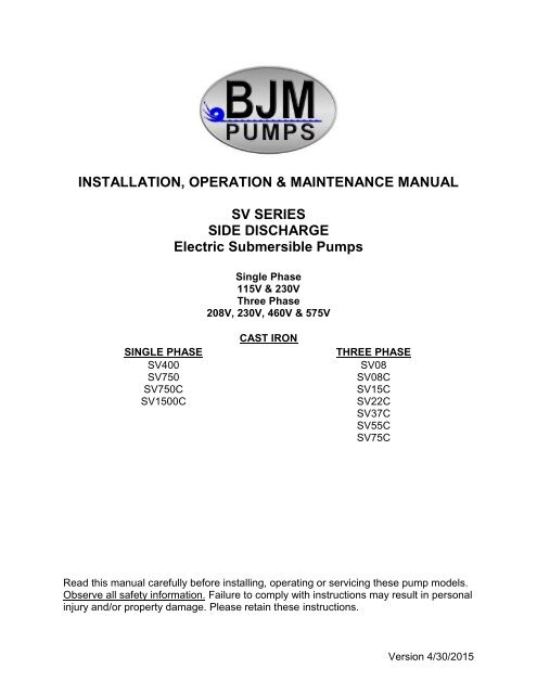
INSTALLATION, OPERATION & MAINTENANCE MANUAL<strong>SV</strong> SERIESSIDE DISCHARGEElectric Submersible <strong>Pumps</strong>Single Phase115V & 230VThree Phase208V, 230V, 460V & 575VSINGLE PHASE<strong>SV</strong>400<strong>SV</strong>750<strong>SV</strong>750C<strong>SV</strong>1500CCAST IRONTHREE PHASE<strong>SV</strong>08<strong>SV</strong>08C<strong>SV</strong>15C<strong>SV</strong>22C<strong>SV</strong>37C<strong>SV</strong>55C<strong>SV</strong>75CRead this manual carefully before installing, operating or servicing these pump models.Observe all safety information. Failure to comply with instructions may result in personalinjury and/or property damage. Please retain these instructions.Version 4/30/2015
TABLE OF CONTENTSINTRODUCTION ............................................................................................................................................................ 4SAFETY ......................................................................................................................................................................... 5INSPECTION ................................................................................................................................................................. 6PRE-INSTALLATION INSPECTION ......................................................................................................................... 6OIL FILL QUANTITY/TYPE ....................................................................................................................................... 6PUMP INSTALLATION ............................................................................................................................................. 7POSITIONING THE PUMP ....................................................................................................................................... 7PUMP ROTATION .................................................................................................................................................... 8PUMP OPERATION ....................................................................................................................................................... 9TYPICAL MANUAL DEWATERING INSTALLATION ..................................................................................................... 9MANUAL OPERATION ............................................................................................................................................. 9STOPPING .............................................................................................................................................................. 10TYPICAL AUTOMATIC DEWATERING INSTALLATION ............................................................................................ 11AUTOMATIC OPERATION ..................................................................................................................................... 11STOPPING .............................................................................................................................................................. 12INTENDED METHODS OF CONNECTION ................................................................................................................. 12SINGLE PHASE WIRING INSTRUCTIONS ............................................................................................................ 12THREE PHASE WIRING INSTRUCTIONS ............................................................................................................. 13TROUBLE SHOOTING ................................................................................................................................................ 15PUMP WILL NOT RUN ........................................................................................................................................... 15PUMP RUNS BUT DOES NOT DELIVER RATED CAPACITY ............................................................................... 15SERVICING YOUR SUBMERSIBLE PUMP............................................................................................................ 15MAINTAINING YOUR PUMP .................................................................................................................................. 15CHANGING SEAL OIL ............................................................................................................................................ 16EXPLODED VIEW OF <strong>SV</strong>400 ...................................................................................................................................... 17EXPLODED VIEW OF <strong>SV</strong>750 ...................................................................................................................................... 18EXPLODED VIEW OF <strong>SV</strong>750C ................................................................................................................................... 19EXPLODED VIEW OF <strong>SV</strong>1500 .................................................................................................................................... 20EXPLODED VIEW OF <strong>SV</strong>08 ........................................................................................................................................ 21EXPLODED VIEW OF <strong>SV</strong>08C ..................................................................................................................................... 22EXPLODED VIEW OF <strong>SV</strong>15C ..................................................................................................................................... 23EXPLODED VIEW OF <strong>SV</strong>22C, <strong>SV</strong>37C ........................................................................................................................ 24EXPLODED VIEW OF <strong>SV</strong>55C, <strong>SV</strong>75C ........................................................................................................................ 25<strong>SV</strong> SERIES PARTS LIST ............................................................................................................................................. 26SINGLE PHASE WIRING DIAGRAM 115V & 230V W/GOVERNOR SWITCH............................................................ 28MODELS <strong>SV</strong>400, <strong>SV</strong>750, <strong>SV</strong>750C, <strong>SV</strong>1500C ................................................................................................... 28THREE PHASE WIRING DIAGRAMS ......................................................................................................................... 29208V ........................................................................................................................................................................ 29MODELS <strong>SV</strong>08, <strong>SV</strong>08C, <strong>SV</strong>15C, <strong>SV</strong>22C, <strong>SV</strong>37C, <strong>SV</strong>55C ................................................................................ 29230V ........................................................................................................................................................................ 30MODELS <strong>SV</strong>08, <strong>SV</strong>08C, <strong>SV</strong>15C, <strong>SV</strong>22C, <strong>SV</strong>37C, <strong>SV</strong>55C, <strong>SV</strong>75C ................................................................... 30460V ........................................................................................................................................................................ 31MODELS <strong>SV</strong>08, <strong>SV</strong>08C, <strong>SV</strong>15C, <strong>SV</strong>22C, <strong>SV</strong>37C, <strong>SV</strong>55C, <strong>SV</strong>75C ................................................................... 31575V ........................................................................................................................................................................ 32MODELS <strong>SV</strong>08, <strong>SV</strong>08C, <strong>SV</strong>15C, <strong>SV</strong>22C, <strong>SV</strong>37C, <strong>SV</strong>55C, <strong>SV</strong>75C ................................................................... 32SEAL MINDER ............................................................................................................................................................. 33WARRANTY AND LIMITATION OF LIABILITY ............................................................................................................ 35START-UP REPORT FORM ........................................................................................................................................ 36NOTES: ........................................................................................................................................................................ 39
INTRODUCTIONThis Installation, <strong>Operation</strong> and Maintenance manual provides important information onsafety and the proper inspection, disassembly, reassembly and testing of the <strong>BJM</strong><strong>Pumps</strong> <strong>SV</strong> <strong>Series</strong> submersible pump. This manual also contains information to optimizeperformance and longevity of your <strong>BJM</strong> submersible pump.The submersible <strong>SV</strong> <strong>Series</strong> pumps are designed to pump municipal and industrialwastewater. The <strong>SV</strong> <strong>Series</strong> pumps are not explosion-proof. They are not designedto pump volatile or flammable liquids.Note: Consult chemical resistance chart for compatibility between pumpmaterials and liquid before operating pump.If you have any questions regarding the inspection, disassembly, reassembly or testingplease contact your <strong>BJM</strong> <strong>Pumps</strong> distributor, or <strong>BJM</strong> <strong>Pumps</strong>, LLC.<strong>BJM</strong> <strong>Pumps</strong>, LLC123 Spencer Plain RdOld Saybrook, CT 06475, USAPhone: 877-256-7867Phone: 860-399-5937Fax: 860-399-7784Information, including pump data sheets and performance curves, is also available onour web site: www.bjmpumps.comFor assistance with your electric power source, please contact a certified electrician.Please pay attention to the following alert notifications. They are used to notifyoperators and maintenance personnel to pay special attention to procedures, to avoidcausing damage to the equipment, and to avoid situations that could be dangerous topersonnel.NOTE: Instructions to aid in installation, operation, and maintenance or whichclarify a procedure.Immediate hazards that WILL result in severe personal injury ordeath. These instructions describe the procedure required and the injury which willresult from failure to follow the procedure.Hazards or unsafe practices that COULD result in severe personalinjury or death. These instructions describe the procedure required, and the injury whichcould result from failure to follow the procedure.Hazards or unsafe practices which COULD result in personal injuryor product or property damage. These instructions describe the procedure required andthe possible damage which could result from failure to follow the procedure.4
SAFETYPump installations are seldom identical. Each installation and application can vary dueto many different factors. It is the owner/service mechanics responsibility to repair,service, and test to ensure that the pump integrity is not compromised according to thismanual.Risk of electric shock – this pump has not been investigated for usein swimming pool areas.Do not pump flammable, inflammable or volatile liquids. Deathor serious injury will result.Before attempting to open or service the pump:1) Familiarize yourself with this manual.2) Unplug or disconnect the pump power cable to ensure that the pump will remaininoperative.3) Allow the pump to cool if overheated.Do not operate the pump with a worn or damaged electric powercable. Death or serious injury could occur.Never attempt to alter the length or repair any power cable with asplice. The pump motor and pump motor and cable must be completely waterproof.Damage to the pump or personal injury may result from alterations.After the pump has been installed, make sure that the pump and allpiping are secure before operation.Do not lift the pump by the power cable piping or discharge hose.Attach proper lifting equipment to the lifting handle (or lifting rings) fitted to the pump. Donot suspend the pump by the power cable.Obtain the services of a qualified electrician to troubleshoot, testand/or service the electrical components of this pump.<strong>Pumps</strong> and related equipment must be installed and operatedaccording to all national, local and industry standards.5
INSPECTIONReview all safety information before servicing pump.The following are recommended installation practices/procedures for the pump. If thereare questions in regards to your specific application, contact your local <strong>BJM</strong> <strong>Pumps</strong>distributor or <strong>BJM</strong> <strong>Pumps</strong>, LLC.PRE-INSTALLATION INSPECTION1) Check the pump for damage that may have occurred during shipment.2) Inspect the pump for any cracks, dents, damaged threads, etc.3) Check power cable (and seal minder cable, if installed) for any cuts or damage.4) Check for, and tighten any hardware that appears loose.5) Carefully read all tags, decals and markings on the pump.6) Important: Always verify that the pump nameplate, amps, voltage, phase, andHP ratings match your control panel and power supply.Warranty does not cover damage caused by connecting pumps and controls to anincorrect power source (voltage/phase supply). Record the model numbers and serialnumbers from the pumps and control panel on the front of this instruction manual forfuture reference. Give it to the owner or affix it to the control panel when finished withthe installation.If anything appears to be abnormal, contact your <strong>BJM</strong> <strong>Pumps</strong> distributor or <strong>BJM</strong> <strong>Pumps</strong>,LLC. If damaged, the pump may need to be repaired before use. Do not install or usethe pump until appropriate action has been taken.Lubrication:No additional lubrication is necessary. The shaft seal and bearings are fully lubricatedfrom the factory. Seal oil should be checked once per year. See table below.OIL FILL QUANTITY/TYPEOil in seal chamberModel U.S. fl. oz. cc. Type of oil<strong>SV</strong>250 5.1 150 ISO 32 NSF Food Grade Mineral Oil<strong>SV</strong>400 5.1 150 ISO 32 NSF Food Grade Mineral Oil<strong>SV</strong>750 9.3 275 ISO 32 NSF Food Grade Mineral Oil<strong>SV</strong>750C 9.3 275 ISO 32 NSF Food Grade Mineral Oil6
<strong>SV</strong>1500C 9.3 275 ISO 32 NSF Food Grade Mineral Oil<strong>SV</strong>08 9.3 275 ISO 32 NSF Food Grade Mineral Oil<strong>SV</strong>08C 9.3 275 ISO 32 NSF Food Grade Mineral Oil<strong>SV</strong>15C 9.3 275 ISO 32 NSF Food Grade Mineral Oil<strong>SV</strong>22C 3.4 100 ISO 32 NSF Food Grade Mineral Oil<strong>SV</strong>37C 3.4 100 ISO 32 NSF Food Grade Mineral Oil<strong>SV</strong>55C 27 800 ISO 32 NSF Food Grade Mineral Oil<strong>SV</strong>75C 27 800 ISO 32 NSF Food Grade Mineral OilNote: EPDM seals will use Propylene glycol instead of ISO 32 NSF Food Grade MineralOil.PUMP INSTALLATION<strong>SV</strong> <strong>Series</strong> pumps have been evaluated for use with water or water based solutions.Please contact the manufacturer for additional information.Risk of electric shock. Pump models; <strong>SV</strong>400, <strong>SV</strong>750 (115v) aresupplied with a grounding conductor and grounding-type attachment plug. 230V singlephase pumps and all three phase pumps do not come with electric plug connectors. Toreduce the risk of electric shock, be certain that it is connected only to a properlygrounded, grounding-type receptacle.Lifting:Attach a rope or lifting chain (not included) to the handle (or lifting rings) on the top ofthe pump.Do not lift the pump by the power cable or discharge hose/piping.Proper lifting equipment (rope/chain) must be used.POSITIONING THE PUMP<strong>BJM</strong> <strong>Pumps</strong>, <strong>SV</strong> <strong>Series</strong> pumps are designed to operate fully or partially submerged.Avoid running the pump dry for extended periods of time. Refer to data sheet forminimum submersion depth for your particular model. Data sheets can be obtainedonline at www.bjmpumps.com or by calling <strong>BJM</strong> <strong>Pumps</strong>, LLC at 860-399-5937. As ageneral rule, <strong>SV</strong> <strong>Series</strong> side discharge pumps can pump down to a level above thesuction cover. Pumping lower than the cover will permit air to enter the pump andcavitate, lose prime or become air bound.7
Do not run the pump dry.Pump liquid should not exceed a maximum temperature of 104°F.Never place the pump on loose or soft ground. The pump may sink, preventingwater from reaching the impeller. Place on a solid surface or suspend the pumpwith a lifting rope/chain. The <strong>SV</strong> <strong>Series</strong> pumps are provided with a suctionstrainer to prevent large solids from clogging the impeller. Any spherical solidswhich pass through the strainer should pass through the pump.For maximum pumping capacity, use the proper size non-collapsible hose or rigidpiping. A check valve may be installed after the discharge to prevent back flowwhen the pump is shut off.PUMP ROTATIONTwo ways to check the correct pump rotation:1. By looking at the impeller; the rotation of the impeller should be counterclockwise as shown in the picture below.2. By looking from the top of the pump. Since the impeller cannot be seen, the bestway to check the rotation is to check the kick back motion of the pump when thepump just starts. The kick back motion of the pump should be counter clockwiseas shown in the picture below.8
PUMP OPERATIONThis pump is designed to handle dirty water that contains somesolids. It is not designed to pump volatile or flammable liquids. Do not attempt to pumpany liquids which may damage the pump or endanger personnel as a result of pumpfailure.Do not operate this pump where explosive vapors orflammable material exist. Death or Serious injury will result.TYPICAL MANUAL DEWATERING INSTALLATIONNOTE: Maximum recommended starts should not exceed 10 times per hour.MANUAL OPERATIONAll <strong>SV</strong> models are provided with a 33’ (10 m) power cable. NEVER splice the powercable due to safety and warranty considerations. Always keep the plug end dry.Note: 230V, single phase and 208V, 230V, 460V & 575V three phase units do nothave a plug and have to be provided separately.Do not alter the length or repair any power cable with a splice. Thepump motor and cable must be completely waterproof. Damage to the pump orpersonal injury may result from alterations.For manual operation: 115 volt: plug the power cable into any 115 volt groundedreceptacle. 208, 230, 460 & 575 volt: Attach the proper plug, connect directly to thepower source or control box. Check the direction of the rotation. Tilt the pump and startit. It should twist in the opposite direction of the arrow (on pump). It is recommendedthat a Ground Fault Interrupter (GFI) type receptacle (or equivalent) be used.9
Single phase pumps always use a three-prong groundedreceptacle. It is recommended that a Ground Fault Interrupter (GFI) type receptacle (orequivalent) be used.STOPPINGTo stop the pump (manual and automatic mode), unplug it from the power source, turnoff the breaker, or turn the power source off (generator).Typical 3 phase manual control 110
TYPICAL AUTOMATIC DEWATERING INSTALLATIONNOTE: Maximum recommended starts should not exceed 10 times per hour.AUTOMATIC OPERATIONFloat switches (wired into the pump motor or piggy-back style) are available from thefactory as an option.Note: 208V, 230V, 460V & 575V pumps do not have a plug installed.Three phase pumps need a separate control box with float(s) for automaticoperation.11
STOPPINGTo stop the pump (manual and automatic mode), unplug it from the power source, turnoff the breaker, or turn the power source off (generator).INTENDED METHODS OF CONNECTIONUse with approved motor control that matches motor input in fullload amperes. “UTILLISER UN DÉMARREAR APPROUVÉ CONVENANT AUCOURANT Á PLEINE CHARGE DU MOTEUR.”<strong>BJM</strong> <strong>Pumps</strong> has been evaluated for use with water or water based solutions. Pleasecontact the manufacturer for additional information.SINGLE PHASE WIRING INSTRUCTIONSFOR YOUR PROTECTION, ALWAYS DISCONNECT PUMPFROM ITS POWER SOURCE BEFORE HANDLING. Single phase pumps are suppliedwith a three prong grounded plug to help protect you against the possibility of electricalshock. DO NOT UNDER ANY CIRCUMSTANCES REMOVE THE GROUND PIN. Thethree prong plug must be inserted into a mating three prong grounded receptacle. IFthe installation does not have such a receptacle it must be changed to the proper type,wired and grounded in accordance with the National Electrical Code and all applicablelocal codes and ordinances.12
“Risk of electrical shock” Do not remove power supply cable andstrain relief or connect conduit directly to the pump.Installation and checking of electrical circuits and hardware shouldbe performed by a qualified licensed electrician.THREE PHASE WIRING INSTRUCTIONSFOR YOUR PROTECTION, ALWAYS DISCONNECT PUMPFROM ITS POWER SOURCE BEFORE HANDLING.“Risk of electrical shock” Do not remove power supply cable andstrain relief or connect conduit directly to the pump.Installation and checking of electrical circuits and hardware shouldbe performed by a qualified licensed electrician.To automatically operate a non-automatic three phase pump, a control panel isrequired. Follow the instructions provided with the panel to wire the system. Forautomatic three phase pumps see automatic three phase wiring diagram.13
Typical 3 phase Auto Control 1Before installing a pump, check the pump rotation to insure that wiring has beenconnected properly to power source, and that the green lead of power cable (See wiringdiagram), is connected to a valid ground, momentarily energize the pump, observing thedirections of kick back due to starting torque. Rotation is correct if kick back is in theopposite direction of rotation arrow on the pump casing. If rotation is not correct,switching of any two power leads other than ground will provide the proper rotation.DO NOT PLACE HANDS IN PUMP SUCTION WHILE CHECKINGMOTOR ROTATION. TO DO SO WILL CAUSE SEVERE PERSONAL INJURY.<strong>BJM</strong> three phase pumps have integral motor overload protection. <strong>BJM</strong> recommendsthat all three phase pumps using a motor starting device also incorporate motoroverload protection. <strong>Pumps</strong> must be installed in accordance with the National ElectricalCode and all applicable local codes and ordinances. <strong>Pumps</strong> are not to be installed inlocations classified as hazardous in accordance with National Electrical Code,ANSI/NFPA 70.Connect pump to a junction box, outlet box, control box, enclosure with a wiringcompartment that meets NEC and local codes. The provision for supply connection14
shall reduce the risk of water entry during temporary, limited submersion and shallcomply with the applicable requirements of the Standard for Enclosures for ElectricalEquipment, UL 50, or the standard for Metallic Outlet Boxes, UL 514A, and the standardfor Motor-Operated Water <strong>Pumps</strong>. UL 778.TROUBLE SHOOTINGDisconnect the power source to the pump BEFORE attemptingany type of trouble shooting, service or repair.PUMP WILL NOT RUN1. Check power supply (fuses, breaker). Reset power.2. Blocked impeller. Remove strainer, check and clean.3. Defective cable or incorrect wiring.4. Strainer clogged. Check and clean as necessary.5. Float switch tangled/obstructed. Clean and free float switch from obstruction.6. Float switch defective. Replace float switch.7. Pump overheated or temperature of liquid exceeds pump operatingtemperature.Warning: Pump will restart automatically when motor over-heat protection switchcools.PUMP RUNS BUT DOES NOT DELIVER RATED CAPACITY1. Discharge line clogged, restricted or hose kinked. Check discharge hose/pipe.2. Worn impeller and/or suction cover. Inspect and replace as necessary.3. Pump overloaded due to liquid pumped being too thick.4. Pumping air. Check liquid level and position of pump.5. Excessive voltage drops due to long cables.6. Three phase only; pump running backwards, check rotation.SERVICING YOUR SUBMERSIBLE PUMPPump should be disconnected from the electric power supply before proceeding to doany service or maintenance.To service or repair your pump, please contact your local <strong>BJM</strong> <strong>Pumps</strong> distributor.Service should only be performed by a qualified electrician.MAINTAINING YOUR PUMPPump should be disconnected from the electric power supply before proceedingto do any service or maintenance.15
Pump should be inspected at regular intervals.More frequent inspections are required if the pump is used in a harshenvironment.Preventative maintenance should be performed to reduce the chance ofpremature failure.Worn impellers and lip seals should be replaced.Cut or cracked power cables must be replaced. (Never operate a pump with acut, cracked or damaged power cable.)Seal oil should be checked once per year.Maintenance should always be done when taking a pump out of service beforestorage.1) Clean pump of dirt and other build up.2) Check condition of oil around the shaft seals.3) Check hydraulic parts: check for wear.4) Inspect power cable. Make sure that it is free of nicks or cuts.CHANGING SEAL OILChanging the seal oil in the <strong>SV</strong> series pumps is very easy.1) Make sure that the pump cable is disconnected from the power source.2) Lay the pump down on its side.3) Remove the screws that hold the bottom plate in place.4) Remove bottom plate.5) Remove screws holding the suction cover.6) Remove the suction cover.7) Remove the impeller.8) Remove the inspection screw for the oil chamber (pos#50-08). Pourout a small sample of the oil. If it is milky white, or contains water, thenthe oil and possible, the mechanical seal, should be changed. If an oilchange is needed:9) Remove the screws that hold the oil chamber cover in place & removethe oil.10) Replace the mechanical seal if necessary.11) Replace the oil.12) Reassemble the pump.16
EXPLODED VIEW OF <strong>SV</strong>40017
EXPLODED VIEW OF <strong>SV</strong>75018
EXPLODED VIEW OF <strong>SV</strong>750C19
EXPLODED VIEW OF <strong>SV</strong>1500C20
EXPLODED VIEW OF <strong>SV</strong>0821
EXPLODED VIEW OF <strong>SV</strong>08C22
EXPLODED VIEW OF <strong>SV</strong>15C23
EXPLODED VIEW OF <strong>SV</strong>22C, <strong>SV</strong>37C24
EXPLODED VIEW OF <strong>SV</strong>55C, <strong>SV</strong>75C25
<strong>SV</strong> SERIES PARTS LISTPump Model <strong>SV</strong>250 <strong>SV</strong>400 <strong>SV</strong>750 <strong>SV</strong>750C <strong>SV</strong>1500C <strong>SV</strong>08 <strong>SV</strong>08C <strong>SV</strong>15C <strong>SV</strong>22C <strong>SV</strong>37C <strong>SV</strong>55C <strong>SV</strong>75CPos. No. Part Description Item # Item # Item # Item # Item # Item # Item # Item # Item # Item # Item # Item #01-2 Bottom Plate 202868 202868 202037 202037 202035 202037 202037 202035 201018 201018 202036 20203603 Impeller Nut 202890 - - - - 202894 202894 202894 202894 202894 202895 20289504 Washer - - - - - 202907 202907 202907 202907 202907 202904 20290405 Impeller Vortex 202923 202114 202115 202115 202116 202118 202118 202119 202120 202121 202129 20213006 Impeller Key - - - - - 202140 202140 202140 202140 202140 202141 20214107 Pump Housing w/ Bottom Plate 202185 202185 202186 203016 202187 202186 203016 202187 202188 202188 203023 20302307-1 O-Ring (Kit Only) Kit Kit Kit Kit Kit Kit Kit Kit Kit Kit - -08 Oil Chamber Cover 202207 202207 202211 203045 202211 202211 203045 202211 203046 203046 203048 20304808-1 O-Ring (Kit Only) Kit Kit Kit Kit Kit Kit Kit Kit Kit Kit Kit Kit09 Lip Seal Buna-N 202229 202229 202231 202231 202231 202231 202231 202231 202247 202247 202239 20223910 Shaft Sleeve 202258 202258 - - - - - - - - - -12 Lip Seal Buna-N - - - - - - - - - - 202236 20223613 Mechanical Seal Buna-N 202259 202259 200501 200501 200501 200501 200501 200501 200302 200302 200305 20030513 Mechanical Seal FKM** 202260 202260 200500 200500 200500 200500 200500 200500 200301 200301 200304 20030414 Lower Ball Bearing 200493 200493 200958 200958 200958 200958 200958 200958 200959 200959 200961 20096114-1 Lower Ball Bearing - - - - - - - - - - 200961 20096114-2 Lower Bearing Retainer - - - - - - - - - - 202279 20227917 Rotor w/ Shaft 115/ 230V, 1 PH 202305 202302 203086 203086 - - - - - - - -17 Rotor w/ Shaft 230V, 1 PH - - - - 203091 - - - - - - -17 Rotor w/ Shaft, 3PH - - - - - 202306 202306 202310 202322 202323 202347 20234818 Stator Coil w/ Casing 115V, 1PH 1810 200509 200511 200511 - - - - - - - -18 Stator Coil w/ Casing 230V, 1PH 200646 200521 200570 200570 200514 - - - - - - -18 Stator w/ Casing 208V, 3PH - - - - - 200524 200524 200528 200540 200542 200544 -18 Stator w/ Casing 230/460V, 3PH - - - - - 200546 200546 200550 200614 200620 200651 20065318 Stator w/ Casing 575V, 3PH - - - - - 200588 200588 200592 200647 200649 200655 20065719 Governor Switch w/ Switch Plate - 202359 202360 202360 202360 - - - - - - -20 Upper Ball Bearing 200957 200957 200967 200967 200967 200967 200967 200967 200958 200958 200959 20095920-1 O-Ring (Kit Only) - - - - - - - - - Kit Kit21A Oil Chamber Housing 200498 200498 203017 203018 203019 203017 203018 203019 203020 203020 203021 20302121A-1 O-Ring (Kit Only) Kit Kit Kit Kit Kit Kit Kit Kit Kit Kit Kit Kit21B Motor Cover Upper 204154 202365 202368 202368 202368 - - - - - - -22 Motor Cover Plate - 202380 - - - - - - - - - -23 Overload Protector 115V,1PH - - 202383 202383 - - - - - - - -23 Overload Protector 230V, 1PH - - 202395 202395 202383 - - - - - - -23 Overload Protector 208V, 3PH - - - - - 202385 202385 202388 202390 202392 202394 -23 Overload Protector 230V, 3PH - - - - - 202385 202385 202388 202390 202392 202394 20239623 Overload Protector 460V, 3PH - - - - - 202387 202387 202386 202389 202391 202393 20239423 Overload Protector 575V, 3PH - - - - - 202399 202399 202387 202386 202389 202391 20239324 Capacitor 115V 202412 202415 202417 202417 - - - - - - - -24 Capacitor 230V 202413 202416 202418 202418 202420 - - - - - - -26 Pump Top Cover 203120 203120 202433 202433 202433 202435 202435 202435 202445 202445 202439 20243926-1 O-Ring (Kit Only) Kit Kit Kit Kit Kit Kit Kit Kit Kit Kit Kit Kit27 Power Cable w/ Gland-115V,1PH 201682 204257 204258 204258 - - - - - - - -26
27 Power Cable w/ Gland-230V, 1PH, No Plug 201684 201684 201694 201694 201694 - - - - - - -27 Power Cable w/ Gland- 3PH - - - - - 201701 201701 201701 203442 203444 203446 20344627-1 O-Ring (Kit Only) Kit Kit Kit Kit Kit Kit Kit Kit Kit Kit Kit Kit27-2 Seal Minder Cable - - 202763 202763 202763 202763 202763 202763 202763 202763 202763 20276327-2-1 O-Ring (Kit Only) - - Kit Kit Kit Kit Kit Kit Kit Kit Kit Kit27-3 Oil Sensor Cap - - 203139 203139 203139 203139 203139 203139 203139 203139 203139 20313931D Seal Minder Probe - - 202409 202409 202409 202409 202409 202409 203998 203998 204000 20400031E Ground Wire w/ Ring Term. 203145 203145 203145 203145 203145 203145 203145 203145 203145 203145 203145 20314532 Power Cord Line Clip 203161 203161 203161 203161 203161 203161 203161 203161 204161 204161 204161 20416133 Seal Minder Cable Line Clip - - 203163 203163 203163 203163 203163 203163 203163 203163 203163 20316334 Handle 202517 202517 202517 202517 202517 202517 202517 202517 202517 202517 203171 20317135 Rods Bolts 202675 202665 202666 202666 202668 202669 202669 202670 202671 202672 202673 20267438 Discharge Nipple 2" - 202531 202531 202531 - 202531 202531 - - - - -38 Discharge Nipple 3" - - 202534 202534 202534 202534 202534 202534 202534 202534 - -38E Discharge Elbow - - - 202558 202557 - 202558 202557 202557 202557 202572 20257238E-1 Gasket, Disch. Elbow, Buna-N - - - 203208 203208 - 203208 203208 203208 203208 203210 20321038F Discharge Flange 2", 45° 202569 202569 - - - - - - - - - -38F Discharge Flange 2" - 202562 202543 202543 - 202543 202543 - - - - -38F Discharge Flange 3" - - 202545 202545 203188 202545 202545 203188 203188 203188 - -38F Discharge Flange 4" - - - - 202606 - - 202606 202606 202606 202575 20257538F Discharge Connection, 4" FNPT - - 202552 202552 - 202552 202552 - - - - -38F-1 Gasket, Disch. Flange, Buna-N 203206 203206 202659 202659 201564 202659 202659 201564 201564 201564 202661 20266150-01-2 Screw for Bottom Plate 203216 203216 203216 203216 203216 203216 203216 203216 203220 203220 203220 20322050-07 Screw for Pump Housing 203238 203238 203283 203283 203283 203283 203283 203283 203229 203229 203229 20322950-08 Screw for Oil Chamber Cover 203215 203215 203219 203219 203219 203219 203219 203219 203219 203219 203220 20322050-11 Screw for Oil Fill 203218 203218 203218 203218 203218 203218 203218 203218 203218 203218 203218 20321850-11-1 O-Ring (Kit Only) Kit Kit Kit Kit Kit Kit Kit Kit Kit Kit Kit Kit50-12 Screw for Pressure Check 203218 203218 203218 203218 203218 203218 203218 203218 203218 203218 203218 20321850-12-1 O-Ring (Kit Only) Kit Kit Kit Kit Kit Kit Kit Kit Kit Kit Kit Kit50-14-2 Screw Bearing Retainer - - - - - - - - - - 203219 20321950-19 Screw for Gov. Switch - 202693 202693 202693 202693 - - - - - - -50-19B Screw for Gov. Switch Plate - 203215 - - - - - - - - - -50-22 Screw for Cover Plate - 203214 - - - - - - - - - -50-23 Screw for Overload - - 202700 202700 202700 202700 202700 202700 202700 202700 202700 20270050-27 Screw for Power Cord 203295 203295 203216 203216 203216 203216 203216 203216 203220 203220 203220 20322050-27-2 Screw for Seal Minder Cable - - 203216 203216 203216 203216 203216 203216 203216 203216 203216 20321650-31E Screw for Ground Wire 202692 202692 202692 202692 202692 202692 202692 202692 202692 202692 202692 20269250-32 Screw for Line Clip 203214 203214 203214 203214 203214 203214 203214 203214 - - - -50-33 Screw for Line Clip - - 203214 203214 203214 203214 203214 203214 203214 203214 - -50-34 Bolt for Handle 203219 203219 203219 203219 203219 203219 203219 203219 203219 203219 - -50-34-1 Bolt for Handle w/ Cable Chain - - - - - - - - - - 203228 20322850-34-2 Bolt for Handle - - - - - - - - - - 203288 20328850-34-3 Lock Washer - - - - - - - - - - 202902 20290250-38E Bolt for Discharge Elbow - - - 203267 203267 - 203267 203267 203267 203267 203286 20328650-38F Bolt for Discharge Flange 203230 203230 203253 203253 203277 203253 203253 203277 203277 203277 203277 203277O-Ring Kit - Buna N 203191 203191 202634 202634 202634 203192 203192 203192 203193 203193 202650 20265027
SINGLE PHASE WIRING DIAGRAM 115V & 230V W/GOVERNOR SWITCHMODELS <strong>SV</strong>400, <strong>SV</strong>750, <strong>SV</strong>750C, <strong>SV</strong>1500C28
THREE PHASE WIRING DIAGRAMS208VMODELS <strong>SV</strong>08, <strong>SV</strong>08C, <strong>SV</strong>15C, <strong>SV</strong>22C, <strong>SV</strong>37C, <strong>SV</strong>55C29
230VMODELS <strong>SV</strong>08, <strong>SV</strong>08C, <strong>SV</strong>15C, <strong>SV</strong>22C, <strong>SV</strong>37C, <strong>SV</strong>55C, <strong>SV</strong>75C30
460VMODELS <strong>SV</strong>08, <strong>SV</strong>08C, <strong>SV</strong>15C, <strong>SV</strong>22C, <strong>SV</strong>37C, <strong>SV</strong>55C, <strong>SV</strong>75C31
575VMODELS <strong>SV</strong>08, <strong>SV</strong>08C, <strong>SV</strong>15C, <strong>SV</strong>22C, <strong>SV</strong>37C, <strong>SV</strong>55C, <strong>SV</strong>75C32
SEAL MINDER33
<strong>BJM</strong> PUMPS, LLC123 Spencer Plain RoadOld Saybrook, CT 06475, U.S.A.WARRANTY AND LIMITATION OF LIABILITYUnless otherwise expressly authorized in writing, specifying a longer or shorter period, <strong>BJM</strong><strong>Pumps</strong>, LLC warrants for a period of eighteen (18) months from the date of shipment from thePoint of Shipment, or one (1) year from the date of installation, whichever occurs first, that allproducts or parts thereof furnished by <strong>BJM</strong> <strong>Pumps</strong>, LLC under the brand name <strong>BJM</strong> <strong>Pumps</strong>,hereinafter referred to as the “Product” are free from defects in materials and workmanship andconform to the applicable specification.<strong>BJM</strong> <strong>Pumps</strong>, LLC’s liability for any breach of this warranty shall be limited solely to replacementor repair, at the sole option of <strong>BJM</strong> <strong>Pumps</strong>, LLC, of any part or parts of the Product found to bedefective during the warranty period, provided the Product is properly installed and is beingused as originally intended. Any breach of this warranty must be reported to <strong>BJM</strong> <strong>Pumps</strong>, LLCor <strong>BJM</strong> <strong>Pumps</strong>, LLC’s authorized service representative within the aforementioned warrantyperiod, and defective Product or parts thereof must be shipped to <strong>BJM</strong> <strong>Pumps</strong>, LLC or <strong>BJM</strong><strong>Pumps</strong>, LLC’s authorized representative, transportation charges prepaid. Any cost associatedwith removal or installation of a defective Product or part is excluded.IT IS EXPRESSLY AGREED THAT THIS SHALL BE THE SOLE AND EXCLUSIVE REMEDYOF <strong>BJM</strong> PUMPS, LLC’S DISTRIBUTORS AND CUSTOMERS. UNDER NO CIRCUMSTANCESSHALL <strong>BJM</strong> PUMPS, LLC BE LIABLE FOR ANY COSTS, LOSS, EXPENSE, DAMAGES,SPECIAL DAMAGES, INCIDENTAL DAMAGES OR CONSEQUENTIAL DAMAGES ARISINGDIRECTLY OR INDIRECTLY FROM THE DESIGN, MANUFACTURE, SALE, USE OR REPAIROF THE PRODUCT, WHETHER BASED ON WARRANTY, CONTRACT, NEGLIGENCE, ORSTRICT LIABILITY. IN NO EVENT WILL LIABILITY EXCEED THE PURCHASE PRICE OFTHE PRODUCT.THE WARRANTY AND LIMITS OF LIABILITY CONTAINED HEREIN ARE IN LIEU OF ALLOTHER WARRANTIES AND LIABILITIES, EXPRESSED OR IMPLIED. ALL IMPLIEDWARRANTIES OF MERCHANTABILITY AND FITNESS FOR A PARTICULAR PURPOSE AREHEREBY DISCLAIMED BY <strong>BJM</strong> PUMPS, LLC AND EXCLUDED FROM THIS WARRANTY.<strong>BJM</strong> <strong>Pumps</strong>, LLC neither assumes, nor authorizes any person to assume for it, any otherwarranty obligation in connection with the sale of the Product. This warranty shall not apply toany Product or parts of Product which have (a) been repaired or altered outside of <strong>BJM</strong> <strong>Pumps</strong>,LLC’s facilities unless such repair was authorized in advance by <strong>BJM</strong> <strong>Pumps</strong>, LLC or by itsauthorized representative; or (b) have been subject to misuse, negligence or accident; or (c)have been used in a manner contrary to <strong>BJM</strong> <strong>Pumps</strong>, LLC’s instruction.In any case of products not manufactured and sold under the <strong>BJM</strong> <strong>Pumps</strong>, LLC brand name,there is no warranty from <strong>BJM</strong> <strong>Pumps</strong>, LLC; however <strong>BJM</strong> <strong>Pumps</strong>, LLC will extend any warrantyreceived from <strong>BJM</strong> <strong>Pumps</strong>, LLC’s supplier of such products.35
START-UP REPORT FORMSTART-UP REPORT FORMThis form is designed to record the initial installation, and to serve as a guide for troubleshooting at alater date (if needed).<strong>BJM</strong> <strong>Pumps</strong>, LLC123 Spencer Plain RoadOld Saybrook, CT. 06475Pump Owner’s NameLocation of InstallationDate of Installation:Dealer Dealer Phone ( )Date of PurchaseModelSerial NoVoltage Phase Hertz HPDoes impeller turn freely by hand? Yes NoCondition of Equipment New Good Fair PoorCondition of Cable Jacket New Good Fair PoorRotation: Direction of Impeller Rotation (viewed from bottom)(Use C/W for clockwise, CC/W for counterclockwise):Resistance of cable and Pump Motor (measured at pump control)Red-Black ohms Red-White ohms White-Black ohmsResistance of ground circuit between control panel and outside of pumpsOhmsMEG OHM CHECK OF INSULATIONRed to ground White to ground Black to groundCondition of location at start-up Dry Wet MuddyWas equipment storedIf YES, length of storage:Yes No.Liquid being pumpDebris in bottom of station? Yes No
START-UP REPORT FORMAre guide rails vertical? Yes NoIs base elbow installed level? Yes NoLiquid level controls: ModelIs control installed away from turbulence? Yes NoFloat <strong>Operation</strong> CheckTip lowest float (stop float), all pumps should remain off.Tip second float (and stop float), one pump comes on.Tip third float (and stop float), both pumps on (alarm on simplex).Tip fourth float (and stop float), high level alarm on (omit on simplex).Check here if using manual on/off only.Does liquid level ever drop below volute top? Yes NoControl Panel MFG & model no.Number of pumps operated by control panelNOTE: At no time should hole be made in top of control panel, unless proper sealingdevices are utilized.Short Circuit protection:Type:Number and size of short circuit device(s)Amp rating:Overload type: Size: Amp rating:Do protective devices comply with pump motor amprating?Are all pump connections tight? Yes NoYesNoIs the interior of the panel dry?Electrical readingsYes NoIf No, correct moisture problem.SINGLE PHASEVoltage supply at panel line connection, pump off L1 L2Voltage supply at panel line connection, pump on L1 L2Amperage load connection, pump on L1 L2THREE PHASEVoltage supply at panel line connection, pump offL1-L2 L2-L3 L3-L1Voltage supply at panel line connection, pump on
START-UP REPORT FORML1-L2 L2-L3 L3-L1Amperage load connection, pump onL1 L2 L3FINAL CHECKIs pump secured properly? Yes NoWas pump checked for leaks? Yes NoDo check valves operate properly? Yes NoFlow: Do pumps appear to operate at proper rate? Yes NoComments:Noise level: Acceptable UnacceptableInstalled by:Company:Person:Date:
NOTES:
123 Spencer Plain Road • PO Box 1138 • Old Saybrook, CT 06475, USA• Phone: (860) 399-5937 • Fax: (860) 399-7784Email: sales@bjmpumps.com • Web Site: www.bjmpumps.comSeal Minder is a trademark of <strong>BJM</strong> <strong>Pumps</strong>, LLCCopyright © 2009-2013 <strong>BJM</strong> <strong>Pumps</strong>, LLC. All rights reserved.