HAZ-Series Operation Manual - BJM Pumps
HAZ-Series Operation Manual - BJM Pumps
HAZ-Series Operation Manual - BJM Pumps

Create successful ePaper yourself
Turn your PDF publications into a flip-book with our unique Google optimized e-Paper software.
INSTALLATION, OPERATION & MAINTENANCE MANUAL<strong>HAZ</strong> SERIESTOP DISCHARGEElectric Submersible <strong>Pumps</strong><strong>HAZ</strong>37<strong>HAZ</strong>55CAST IRONThree Phase230V & 460V<strong>HAZ</strong>55CH<strong>HAZ</strong>75Read this manual carefully before installing, operating or servicing these pump models.UObserve all safety information.U Failure to comply with instructions may result in personalinjury and/or property damage. Please retain these instructions.Version 11/3/2014
TABLE OF CONTENTSCAUTION STATEMENT ............................................................................................................................... 4INTRODUCTION ........................................................................................................................................... 5HSAFETY ........................................................................................................................................................ 5INSPECTION ................................................................................................................................................ 6PRE-INSTALLATION INSPECTION ........................................................................................................ 6OIL FILL QUANTITY/TYPE ...................................................................................................................... 6PUMP INSTALLATION ............................................................................................................................. 6POSITIONING THE PUMP ....................................................................................................................... 7PUMP ROTATION .................................................................................................................................... 8PUMP OPERATION ...................................................................................................................................... 9TYPICAL MANUAL DEWATERING INSTALLATION ................................................................................... 9MANUAL OPERATION ............................................................................................................................. 9STOPPING ............................................................................................................................................... 9TYPICAL AUTOMATIC DEWATERING INSTALLATION ............................................................................. 9STOPPING ............................................................................................................................................. 10INTENDED METHODS OF CONNECTION ............................................................................................... 11THREE PHASE WIRING INSTRUCTION .............................................................................................. 11TROUBLE SHOOTING ............................................................................................................................... 13PUMP WILL NOT RUN ........................................................................................................................... 13PUMP RUNS BUT DOES NOT DELIVER RATED CAPACITY ............................................................. 13SERVICING YOUR SUBMERSIBLE PUMP .......................................................................................... 13MAINTAINING YOUR PUMP ................................................................................................................. 14CHANGING SEAL OIL ........................................................................................................................... 14CHANGING SEALS* .............................................................................................................................. 15EXPLODED VIEW OF <strong>HAZ</strong>37, 55, 55CH, 75 ............................................................................................. 16<strong>HAZ</strong> SERIES PARTS LIST ......................................................................................................................... 17THREE PHASE WIRING DIAGRAMS ........................................................................................................ 19230V (5 LEAD) ........................................................................................................................................ 19MODELS <strong>HAZ</strong>37, 55, 55CH, 75 ......................................................................................................... 19460V (5 LEAD) ........................................................................................................................................ 20MODELS <strong>HAZ</strong>37, 55, 55CH, 75 ......................................................................................................... 20WARRANTY AND LIMITATION OF LIABILITY ...................................................................................... 21START-UP REPORT FORM ....................................................................................................................... 22NOTES: ....................................................................................................................................................... 25
CAUTION STATEMENTTo retain permissibility of this equipment the following conditions shall be satisfied:1.General Safety. Frequent inspection shall be made. All electrical parts, including the portable cableand wiring, shall be kept in a safe condition. Special efforts shall be made to maintain cable routing pathsfree from mud rock and other debris that could eventually cause cable damage. Cables should be closelyexamined on a regular basis and damaged cables or protective hose conduits shall be replaced and thecause of the damage identified and corrected before the equipment is placed back into service. Thereshall be no openings into the casings of the electrical parts. A permissible distribution box shall be usedfor connection to the power circuit unless connection is made in fresh intake air. To maintain the overloadprotection of direct-current machines, the underground conductor of the portable cable shall be connectedto the proper terminal. The machine frame shall be effectively grounded. The power wires shall not beused for grounding except in conjunction with diode(s) or equivalent. The operating voltage should matchthe voltage rating of the motor(s).2.Servicing. Explosion-proof enclosures shall be restored to the state of original safety with respect to allflame arresting paths, lead entrances, etc. following disassembly for repair or rebuilding, whether by theowner or an independent shop.3.Fastenings. All bolts, nuts, screws and other means of fastening, and also threaded covers, shall be inplace, properly tightened and secured.4.Renewals and Repairs. Inspections, repairs or renewals of electrical parts shall not be made unless theportable cable is disconnected from the circuit furnishing power, and the cable shall not be connectedagain until all parts are properly reassembled. Special care shall be taken in making renewals or repairs.Leave no parts off. Use replacement parts exactly like those furnished by the manufacturer. When anylead entrance is disturbed, the original leads or exact duplicates thereof shall be used and stuffing boxesshall be repacked in the approved manner. When machine cables are replaced or otherwise disturbedfrom their normal position, they shall be routed in the same manner as they were when the machine wasshipped from the manufacturer. In addition, any clamps, conduit or guards, that were in place to preventcable damage shall be replaced.5.Cable Requirements. A flame resistant portable cable bearing a MSHA assigned identification number,adequately protected by an automatic circuit-interrupting device shall be used. Special care shall betaken in handling the cable to guard against mechanical injury and wear. Splices in portable cables shallbe made in a workmanlike manner, mechanically strong, and well insulated. One temporary splice maybe made in any trailing cable. Such trailing cable may only be used for the next 24-hour period. Notemporary splice shall be made in a trailing cable within 25 feet of the machine, except cable reelequipment. Connections and wiring to the outby end of the cable shall be in accordance with recognizedstandards of safety.DO NOT CHANGE WITHOUT APPROVAL OF MSHA4
INTRODUCTIONThis Installation, <strong>Operation</strong> and Maintenance manual provides important information onsafety and the proper inspection, disassembly, reassembly and testing of the <strong>BJM</strong><strong>Pumps</strong>® <strong>HAZ</strong> <strong>Series</strong> submersible pump. This manual also contains information tooptimize performance and longevity of your <strong>BJM</strong> <strong>Pumps</strong> submersible pump.The submersible <strong>HAZ</strong> <strong>Series</strong> pumps are designed to pump water. The <strong>HAZ</strong> <strong>Series</strong>are designed to meet the MSHA requirements for mining pumps, and notdesigned to pump volatile or flammable liquids.Note: Consult chemical resistance chart for compatibility between pumpmaterials and liquid before operating pump.If you have any questions regarding the inspection, disassembly, assembly or testingplease contact your <strong>BJM</strong> <strong>Pumps</strong> distributor, or <strong>BJM</strong> <strong>Pumps</strong>, LLC.<strong>BJM</strong> <strong>Pumps</strong>, LLC123 Spencer Plain Rd.Old Saybrook, CT 06475, USAFax: 860-399-7784Phone: 877-256-7867Phone: 860-399-5937Information, including pump data sheets and performance curves, is also available onour web site: HUwww.bjmpumps.comUFor assistance with your electric power source, please contact a certified electrician.Please pay attention to the following alert notifications. They are used to notifyoperators and maintenance personnel to pay special attention to procedures, to avoidcausing damage to the equipment, and to avoid situations that could be dangerous topersonnel.NOTE: Instructions to aid in installation, operation, and maintenance or whichclarify a procedure.Immediate hazards that WILL result in severe personal injury ordeath. These instructions describe the procedure required and the injury which willresult from failure to follow the procedure.Hazards or unsafe practices that COULD result in severe personalinjury or death. These instructions describe the procedure required, and the injury whichcould result from failure to follow the procedure.Hazards or unsafe practices which COULD result in personal injuryor product or property damage. These instructions describe the procedure required andthe possible damage which could result from failure to follow the procedure.5
HSAFETYPump installations are seldom identical. Each installation and application can vary dueto many different factors. It is the owner/service mechanics responsibility to repair,service, and test to ensure that the pump integrity is not compromised according to thismanual.Risk of electric shock – this pump has not been investigated for usein swimming pool areas.injury will result.Do not pump flammable or volatile liquids. UDeath or seriousBefore attempting to open or service the pump:1) Familiarize yourself with this manual.2) Unplug or disconnect the pump power cable to ensure that the pump will remaininoperative.3) Allow the pump to cool if overheated.Do not operate the pump with a worn or damaged electric powercable. Death or serious injury could occur.Never attempt to alter the length or repair any power cable with asplice. The pump motor and pump motor and cable must be completely waterproof.Damage to the pump or personal injury may result from alterations.After the pump has been installed, make sure that the pump and allpiping are secure before operation.Do not lift the pump by the power cable piping or discharge hose.Attach proper lifting equipment to the lifting handle (or lifting rings) fitted to the pump. Donot suspend the pump by the power cable.Obtain the services of a qualified electrician to troubleshoot, testand/or service the electrical components of this pump.<strong>Pumps</strong> and related equipment must be installed and operatedaccording to all national, local and industry standards.5
INSPECTIONReview all safety information before servicing pump.The following are recommended installation practices/procedures for the pump. If thereare questions in regards to your specific application, contact your local <strong>BJM</strong> <strong>Pumps</strong>distributor or <strong>BJM</strong> <strong>Pumps</strong>, LLC.PRE-INSTALLATION INSPECTION1) Check the pump for damage that may have occurred during shipment.2) Inspect the pump for any cracks, dents, damaged threads, etc.3) Check power cable (and seal minder cable, if installed) for any cuts or damage.4) Check for, and tighten any hardware that appears loose.5) Carefully read all tags, decals and markings on the pump.6) Important: Always verify that the pump nameplate, amps, voltage, phase, andHP ratings match your control panel and power supply.Warranty does not cover damage caused by connecting pumps and controls to anincorrect power source (voltage/phase supply). Record the model numbers and serialnumbers from the pumps and control panel on the front of this instruction manual forfuture reference. Give it to the owner or affix it to the control panel when finished withthe installation.If anything appears to be abnormal, contact your <strong>BJM</strong> <strong>Pumps</strong> distributor or <strong>BJM</strong><strong>Pumps</strong>, LLC. If damaged, the pump may need to be repaired before use. Do not installor use the pump until appropriate action has been taken.Lubrication:No additional lubrication is necessary. The shaft seal and bearings are fully lubricatedfrom the factory. Seal oil should be checked once per year. See table below.OIL FILL QUANTITY/TYPEQty. oil in seal chamberModels U.S. fl. oz. C.C. Type of oil<strong>HAZ</strong>37, 55, 55CH, 75 49 1450Shell FM 32 – Food grade – NSFrated or equalPUMP INSTALLATION<strong>HAZ</strong> <strong>Series</strong> pumps have been evaluated for use with water or water based solutions.Please contact the manufacturer for additional information.6
Risk of electric shock. <strong>HAZ</strong> <strong>Series</strong> pump models do not comewith electric plug connectors. To reduce the risk of electric shock, be certain that it isconnected only to a properly grounded, grounding-type receptacle.Lifting:Attach a rope or lifting chain (not included) to the handle (or lifting rings) on the top ofthe pump.Do not lift the pump by the power cable or discharge hose/piping.Proper lifting equipment (rope/chain) must be used.POSITIONING THE PUMP<strong>BJM</strong> <strong>Pumps</strong>, <strong>HAZ</strong> <strong>Series</strong> pumps are designed to operate fully or partially submerged.Do not run pump dry. Refer to data sheet for minimum submersion depth for yourparticular model. Data sheets can be obtained online at HUwww.bjmpumps.comUH or bycalling <strong>BJM</strong> <strong>Pumps</strong>, LLC at 860-399-5937. As a general rule, <strong>HAZ</strong> <strong>Series</strong> top dischargepumps can pump down to a level above the suction screen. Pumping lower than screenwill permit air to enter the pump and cavitate, lose prime or become air bound.Do not run pump dry.Pump liquid should not exceed a maximum temperature of 104°F.Never place the pump on loose or soft ground. The pump may sink, preventingwater from reaching the impeller. Place on a solid surface or suspend the pumpwith a lifting rope/chain. The <strong>HAZ</strong> <strong>Series</strong> pumps are provided with a suctionstrainer to prevent large solids from clogging the impeller. Any spherical solidswhich pass through the strainer should pass through the pump.For maximum pumping capacity, use the proper size non-collapsible hose or rigidpiping. A check valve may be installed after the discharge to prevent back flowwhen the pump is shut off.7
PUMP ROTATIONTwo ways to check the correct pump rotation:1. By looking at the impeller; the rotation of the impeller should be counterclockwise as shown in the picture below.2. By looking from the top of the pump. Since the impeller cannot be seen, the bestway to check the rotation is to check the kick back motion of the pump when thepump just starts. The kick back motion of the pump should be counter clockwiseas shown in the picture below.8
PUMP OPERATIONThis pump is designed to handle dirty water that contains somesolids. It is not designed to pump volatile or flammable liquids. Do not attempt to pumpany liquids which may damage the pump or endanger personnel as a result of pumpfailure.Do not operate this pump where explosive vapors orflammable material exist. Death or Serious injury will result.TYPICAL MANUAL DEWATERING INSTALLATIONNOTE: Maximum recommended starts should not exceed 10 times per hour.MANUAL OPERATIONAll <strong>HAZ</strong> models are provided with a 50’ (10m) power cord. UNEVERU splice the powercable due to safety and warranty considerations. Always keep the control connectionend of cable dry.Note: 230V & 460V three phase units do not have a plug and have are to be wiredinto a MSHA approved control box/panel.Do not alter the length or repair any power cable with a splice. Thepump motor and cable must be completely waterproof. Damage to the pump orpersonal injury may result from alterations.For manual operation: 230 & 460 volt: Connect directly to an MSHA approved controlbox. Check the direction of the rotation. Tilt the pump and start it. It should twist in theopposite direction of the arrow (on pump). It is recommended that a Ground FaultInterrupter (GFI) type circuit (or equivalent) be used.STOPPINGTo stop the pump (manual and automatic model), turn off the breaker or the powerdisconnect.TYPICAL AUTOMATIC DEWATERING INSTALLATIONNOTE: Maximum recommended starts should not exceed 10 times per hour.9
The <strong>HAZ</strong> <strong>Series</strong> are three phase pumps and need a separate control box with float(s)for automatic operation.STOPPINGTo stop the pump (manual and automatic mode), turn off the breaker or the powerdisconnect.Typical 3 phase manual control 110
INTENDED METHODS OF CONNECTIONUse with approved MSHA motor control that matches motor input infull load amperes. “UTILLISER UN DÉMARREAR APPROUVÉ CONVENANT AUCOURANT Á PLEINE CHARGE DU MOTEUR.”<strong>BJM</strong> <strong>Pumps</strong> submersible pumps have been evaluated for use with water or waterbased solutions. Please contact the manufacturer for additional information.THREE PHASE WIRING INSTRUCTIONFOR YOUR PROTECTION, ALWAYS DISCONNECT PUMPFROM ITS POWER SOURCE BEFORE HANDLING.“Risk of electrical shock” Do not remove power supply cord andstrain relief or connect conduit directly to the pump.Installation and checking of electrical circuits and hardware shouldbe performed by a qualified licensed electrician. See the attached drawing <strong>HAZ</strong>ASSY1for further electrical connection information.To operate a manual three phase pump, a <strong>BJM</strong> MSHA approved control panel isrequired.For automatic three phase pumps a <strong>BJM</strong> MSHA approved control is required. Typicalthree phase automatic wiring diagram shown below.11
Typical 3 phase Auto Control 1Before installing a pump, make sure both of the ground leads and the power leads havebeen connected properly per MSHA requirements. Once the power connections havebeen confirmed, then check the pump rotation. Momentarily energize the pump,observing the directions of kick back due to starting torque. Rotation is correct if kickback is in the opposite direction of the arrow on the pump casing. If rotation is notcorrect, switching of any two power leads other than ground with provide the properrotation.Three phase pumps have integral motor overload protection. It is recommended that allthree phase pumps using a motor starting device also incorporate motor overloadprotection. <strong>Pumps</strong> must be installed in accordance with the MSHA and the NationalElectrical Code requirements as well as all applicable local codes and ordinances. The<strong>HAZ</strong> <strong>Series</strong> pumps are designed for hazardous mine applications only and are not to beinstalled in locations classified as hazardous in accordance with National ElectricalCode, ANSI/NFPA 70.Connect pump to control box/panel that is MSHA approved for the application. Theprovision for supply connection shall reduce the risk of water entry during temporary,limited submersion.12
TROUBLE SHOOTINGDisconnect the power source to the pump BEFORE attemptingany type of trouble shooting, service or repair.PUMP WILL NOT RUN1. Check power supply (fuses, breaker). Reset power.2. Blocked impeller. Remove strainer, check and clean.3. Defective cable or incorrect wiring.4. Strainer clogged. Check and clean as necessary.5. Float switch tangled/obstructed. Clean and free float switch from obstruction.6. Float switch defective. Replace float switch.7. Pump overheated or temperature of liquid exceeds pump operatingtemperature.UWarning: Pump will restart automatically when motor over-heat protection switchcools; Power must be disconnected prior to all servicing!PUMP RUNS BUT DOES NOT DELIVER RATED CAPACITY1. Discharge line clogged, restricted or hose kinked. Check discharge hose/pipe.2. Worn impeller and/or suction cover. Inspect and replace as necessary.3. Pump overloaded due to liquid pumped being too thick.4. Pumping air. Check liquid level and position of pump.5. Excessive voltage drops due to long cables.6. Three phase only; pump running backwards, check rotation.SERVICING YOUR SUBMERSIBLE PUMPPump should be disconnected from the electric power supply before proceeding to doany service or maintenance.To service or repair your pump, please contact your local <strong>BJM</strong> <strong>Pumps</strong> distributor.Service should only be performed by a qualified electrician.13
MAINTAINING YOUR PUMPPump should be disconnected from the electric power supply before proceedingto do any service or maintenance.Pump should be inspected at regular intervals.More frequent inspections are required if the pump is used in a harshenvironment.Preventative maintenance should be performed to reduce the chance ofpremature failure.Worn impellers and lip seals should be replaced.Cut or cracked power cords must be replaced. (Never operate a pump with acut, cracked or damaged power cord.)Seal oil should be checked once per year.Maintenance should always be done when taking a pump out of service beforestorage.1) Clean pump of dirt and other build up.2) Check condition of oil around the shaft seals.3) Check hydraulic parts: check for wear.4) Inspect power cable. Make sure that it is free of nicks or cuts.5)CHANGING SEAL OILChanging the seal oil in the <strong>HAZ</strong> <strong>Series</strong> pumps is very easy.1) Make sure that the pump cable is disconnected from the power source.2) Lay the pump down on its side.3) Remove the screws that hold the bottom plate in place.4) Remove bottom plate.5) Remove screws holding the suction cover.6) Remove the suction cover.7) Remove the impeller.8) Remove the inspection screw for the oil chamber (pos#50-08). Pour out asmall sample of the oil. If it is milky white, or contains water, then the oil andpossible, the mechanical seal, should be changed. If an oil change is needed:9) Remove the screws that hold the oil chamber cover in place & remove the oil.10) Replace the mechanical seal if necessary.11) Replace the oil.12) Assemble the pump.14
CHANGING SEALS*1) Make sure that the pump cable is disconnected from the power source.2) Lay the pump down on its side.3) Remove the oil inspection bolt (pos#50-11) from the oil seal chamber.4) Drain out all the inside the oil seal chamber.5) Remove the bolts holding the stand.6) Remove the stand.7) Remove the bolts holding the suction cover.8) Remove the suction cover.9) Remove the agitator.10) Remove the impeller, impeller key and shims.11) Remove the bolts holding the pump housing.12) Remove the pump housing.13) Remove the shaft sleeve. Note the shaft sleeve direction.14) Remove the bots holding the oil cover.15) Remove the oil cover.16) Remove the screws holding the seal retainer.17) Remove the seal retainer.18) Remove the mechanical seal.19) Replace the mechanical seal, lip seal and o-rings.20) Assemble the pump.21) Fill with recommended new oil.22) Replace the oil inspection bolt o-ring.23) Secure the oil inspection bolt.*Note: If there is excessive liquid found in the oil or mechanical seal damaged, pleasecontact <strong>BJM</strong> <strong>Pumps</strong> authorized service centers.15
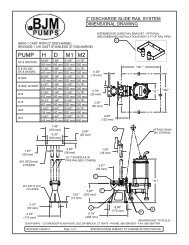
EXPLODED VIEW OF <strong>HAZ</strong>37, 55, 55CH, 7516
<strong>HAZ</strong> SERIES PARTS LISTPump Model<strong>HAZ</strong>37 <strong>HAZ</strong>55 <strong>HAZ</strong>55CH <strong>HAZ</strong>75Pos. No. Part Description Item # Item # Item # Item #01N-01 Stand w/ Strainer Plate 201982 201982 201983 20198202 Wear Plate 202018 202018 202019 20201802W Suction Cover 202869 202869 202870 20287304 Lock Washer 202917 202917 202917 20291705 Impeller 202976 202977 202979 20298005W Agitator 202983 202983 202983 20298306 Impeller Key 202146 202146 202146 20214607 Pump Housing 202191 202191 203026 20219107-3 Pump Housing Sleeve 202182 202182 202182 20218208 Oil Chamber Cover 202225 202225 202225 20222508 -1 O-Ring (Kit Only) Kit Kit Kit Kit09 Lip Seal Buna N 202248 202248 202248 20224810 Shaft Sleeve 203071 203071 203071 20307113 Mech. Seal Set - FKM** 200419 200419 200419 20041913-2 Mech. Seal Retainer 202271 202271 202271 20227114 Lower Ball Bearing 200963 200963 200963 20096314-2 Lower Bearing Retainer 202280 202280 202280 20228016 Motor Housing. 203084 203084 203084 20308517 Rotor w/ Shaft, 3 phase 203108 203109 203109 20311018 Stator 230V/460V 3 phase 200681 200683 200683 20068520 Upper Ball Bearing 200968 200968 200968 20096820-1 O-Ring (Kit Only) Kit Kit Kit Kit20-2 Spring Washer 202361 202361 202361 20236121A Lower Bearing Housing 202378 202378 202378 20237821A-1 O-Ring (Kit Only) Kit Kit Kit Kit23 Overload 230V, 3PH 202392 202394 202394 20239623 Overload 460V, 3PH 202391 202393 202393 20239426 Pump Top Cover 202447 202447 202447 20244726-1 O-Ring (Kit Only) Kit Kit Kit Kit27 Power Cord Set (5 lead) 203144 203144 203144 20314427-1 O-Ring (Kit Only) Kit Kit Kit Kit27-2 Power Cord Housing 202491 202491 202491 20249127-2-1 O-Ring (Kit Only) Kit Kit Kit Kit27-3 Cable Stuffing Box 202486 202486 202486 20248627-3-1 O-Ring (Kit Only) Kit Kit Kit Kit27-4 Cable Gland, AWG 10 Power Cord 203146 203146 203146 20314627-5 Bushing, Cable Gland, AWG 10 202451 202451 202451 20245117
27-6 Bolt - Suction Cover 203147 203147 203147 20314727-7 Dead End Conector 202488 202488 202488 20248831 Power Cord Cable 202749 202749 202749 20274932 Power Cable Strain Relief Holder 202501 202501 202501 20250134 Lift Ring 203172 203172 203172 20317238 3" NPT Male Coupling Flange 202583 202583 202583 -38 4" NPT Male Coupling Flange 202585 202585 202585 20258538B 3" Hose Barb Fitting 202584 202584 202584 -38B 4" Hose Barb Fitting 202586 202586 202586 20258650-01N Bolt - Stand 203258 203258 203258 20325850-02 Bolt - Wear Plate 203253 203253 203253 20325350-02W Bolt - Suction Cover 203236 203236 203236 20323650-07 Bolt - Pump Housing 203271 203271 203271 20327150-08 Bolt - Oil Chamber Cover 202698 202698 202698 20269850-08-1 Lock Washer, Oil Chamber 202902 202902 202902 20290250-11 Bolt - Oil Inspection 203268 203268 203268 20326850-11-1 O-Ring (Kit Only) Kit Kit Kit Kit50-13-2 Screw - Seal Retainer 203214 203214 203214 20321450-14-2 Bolt - Bearing Retainer 202711 202711 202711 20271150-14-2-1 Lock Washer, Bearing Retainer 202909 202909 202909 20290950-21A Bolt - Bearing Housing 202711 202711 202711 20271150-21A-1 Lock Washer, Bearing Housing 202909 202909 202909 20290950-23 Bolt - Overload Protector 202700 202700 202700 20270050-26 Bolt-Top Cover 202712 202712 202712 20271250-26-1 Lock Washer, Top Cover 202905 202905 202905 20290550-27 Bolt - Power Cord 202711 202711 202711 20271150-27-1 Lock Washer, Cable Stuffing Box 202909 202909 202909 20290950-27-2 Hex Bolt, Power Cord Housing 202697 202697 202697 20269750-27-2-1 Lock Washer, Power Cord Housing 202909 202909 202909 20290950-27-2-2 Hex Head Pipe Plug, 202708 202708 202708 20270850-27-2-3 Set Screw 202709 202709 202709 20270950-27-2-4 Lock Wire 203159 203159 203159 20315950-32-1 Bolt- Cable Strain Relief 203256 203256 203256 20325650-32-2 Bolt- Cable Strain Relief 203246 203246 203246 20324650-32-3 Nut, Cable Strain Relief 202889 202889 202889 20288950-32-4 Flat Washer Cable Strain Relief 202049 202049 202049 20204950-32-5 Chain, Cable Strain Relief 202502 202502 202502 20250250-32-6 Pin, Cable Strain Relief 202503 202503 202503 20250350-38 Bolt - Discharge Flange 203262 203262 203262 203262O-Ring Kit - Buna N 203205 203205 203205 20320518
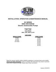
THREE PHASE WIRING DIAGRAMS230V (5 LEAD)MODELS <strong>HAZ</strong>37, 55, 55CH, 7519
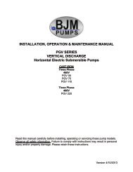
460V (5 LEAD)MODELS <strong>HAZ</strong>37, 55, 55CH, 7520
<strong>BJM</strong> PUMPS, LLC123 Spencer Plain RoadOld Saybrook, CT 06475, U.S.A.WARRANTY AND LIMITATION OF LIABILITYUnless otherwise expressly authorized in writing, specifying a longer or shorter period, <strong>BJM</strong><strong>Pumps</strong>, LLC warrants for a period of eighteen (18) months from the date of shipment from thePoint of Shipment, or one (1) year from the date of installation, whichever occurs first, that allproducts or parts thereof furnished by <strong>BJM</strong> <strong>Pumps</strong>, LLC under the brand name <strong>BJM</strong> <strong>Pumps</strong>,hereinafter referred to as the “Product” are free from defects in materials and workmanship andconform to the applicable specification.<strong>BJM</strong> <strong>Pumps</strong>, LLC’s liability for any breach of this warranty shall be limited solely to replacementor repair, at the sole option of <strong>BJM</strong> <strong>Pumps</strong>, LLC, of any part or parts of the Product found to bedefective during the warranty period, provided the Product is properly installed and is beingused as originally intended. Any breach of this warranty must be reported to <strong>BJM</strong> <strong>Pumps</strong>, LLCor <strong>BJM</strong> <strong>Pumps</strong>, LLC’s authorized service representative within the aforementioned warrantyperiod, and defective Product or parts thereof must be shipped to <strong>BJM</strong> <strong>Pumps</strong>, LLC or <strong>BJM</strong><strong>Pumps</strong>, LLC’s authorized representative, transportation charges prepaid. Any cost associatedwith removal or installation of a defective Product or part is excluded.IT IS EXPRESSLY AGREED THAT THIS SHALL BE THE SOLE AND EXCLUSIVE REMEDYOF <strong>BJM</strong> PUMPS, LLC’S DISTRIBUTORS AND CUSTOMERS. UNDER NO CIRCUMSTANCESSHALL <strong>BJM</strong> PUMPS, LLC BE LIABLE FOR ANY COSTS, LOSS, EXPENSE, DAMAGES,SPECIAL DAMAGES, INCIDENTAL DAMAGES OR CONSEQUENTIAL DAMAGES ARISINGDIRECTLY OR INDIRECTLY FROM THE DESIGN, MANUFACTURE, SALE, USE OR REPAIROF THE PRODUCT, WHETHER BASED ON WARRANTY, CONTRACT, NEGLIGENCE, ORSTRICT LIABILITY. IN NO EVENT WILL LIABILITY EXCEED THE PURCHASE PRICE OFTHE PRODUCT.THE WARRANTY AND LIMITS OF LIABILITY CONTAINED HEREIN ARE IN LIEU OF ALLOTHER WARRANTIES AND LIABILITIES, EXPRESSED OR IMPLIED. ALL IMPLIEDWARRANTIES OF MERCHANTABILITY AND FITNESS FOR A PARTICULAR PURPOSE AREHEREBY DISCLAIMED BY <strong>BJM</strong> PUMPS, LLC AND EXCLUDED FROM THIS WARRANTY.<strong>BJM</strong> <strong>Pumps</strong>, LLC neither assumes, nor authorizes any person to assume for it, any otherwarranty obligation in connection with the sale of the Product. This warranty shall not apply toany Product or parts of Product which have (a) been repaired or altered outside of <strong>BJM</strong> <strong>Pumps</strong>,LLC’s facilities unless such repair was authorized in advance by <strong>BJM</strong> <strong>Pumps</strong>, LLC or by itsauthorized representative; or (b) have been subject to misuse, negligence or accident; or (c)have been used in a manner contrary to <strong>BJM</strong> <strong>Pumps</strong>, LLC’s instruction.In any case of products not manufactured and sold under the <strong>BJM</strong> <strong>Pumps</strong>, LLC brand name,there is no warranty from <strong>BJM</strong> <strong>Pumps</strong>, LLC; however <strong>BJM</strong> <strong>Pumps</strong>, LLC will extend any warrantyreceived from <strong>BJM</strong> <strong>Pumps</strong>, LLC’s supplier of such products.21
START-UP REPORT FORMSTART-UP REPORT FORMThis form is designed to record the initial installation, and to serve as a guide for troubleshooting at alater date (if needed).<strong>BJM</strong> <strong>Pumps</strong>, LLC123 Spencer Plain RoadOld Saybrook, CT. 06475Pump Owner’s NameLocation of InstallationPerson in Charge Phone( )Purchased FromModelSerial NoVoltage Phase Hertz HPDoes impeller turn freelyby hand? Yes NoCondition of Equipment New Good Fair PoorCondition of Cable Jacket New Good Fair PoorRotation: Direction of Impeller Rotation (Use C/W for clockwise, CC/W for counterclockwise):Method used to check rotation (viewed from bottom)Resistance of cable and Pump Motor (measured at pump control)Red-BlackRed-WhiteWhite-BlackohmsohmsohmsResistance of ground circuit between control panel and outside of pumpsOhmsMEG OHM CHECK OF INSULATIONRed to ground White to ground Black to groundCondition of location at start-up Dry Wet MuddyWas equipment storedIf YES, length of storage:YesLiquid being pumpDebris in bottom of station? Yes NoWas debris removed in your Yes NoNo.
START-UP REPORT FORMpresence?Are guide rails exactly vertical? Yes NoIs base elbow installed level? Yes NoLiquid level controls: ModelIs control installed away fromturbulence?Yes<strong>Operation</strong> CheckTip lowest float (stop float), all pumps should remain off.Tip second float (and stop float), one pump comes on.Tip third float (and stop float), both pumps on (alarm on simplex).Tip fourth float (and stop float), high level alarm on (omit on simplex).If not on levels controls, describe type of controlsNoDoes liquid level ever drop belowvolute top?Control Panel MFG & model no.YesNumber of pumps operated by control panelNOTE: At no time should hole be made in top of control panel, unless proper sealingdevices are utilized.Short Circuit protection:Type:NoNumber and size of short circuit device(s) Amp rating:Overload type: Size: Amp rating:Do protective devices comply with Yes Nopump motor amp rating?Are all pump connections tight? Yes NoIs the interior of the panel dry? Yes NoIf No, correct moisture problem.Electrical readingsVoltage supply at panel lineconnection, pump offVoltage supply at panel lineconnection, pump onSINGLE PHASEL1 L2Amperage load connection, pump on L1 L2THREE PHASEVoltage supply at panel line connection, pump offL1L1-L2 L2-L3 L3-L1L2
START-UP REPORT FORMVoltage supply at panel line connection, pump onL1-L2 L2-L3 L3-L1Amperage load connection, pump onL1 L2 L3FINAL CHECKIs pump secured properly? Yes NoWas pump checked for leaks? Yes NoDo check valves operate properly?YesNoFlow: Does station appear to operate atproper rate?YesNoise level: Acceptable UnacceptableComments:NoDescribe and equipment difficulties during start-upInstalled by:Company:Person:Date:Maintained by:Company:Person:Date and time of start-upPresent at start-up:( ) Engineer’s name( )Contractor’s name( ) Operator’s name( ) others
NOTES:
<strong>BJM</strong> <strong>Pumps</strong>, LLC123 Spencer Plain Road • PO Box 1138 • Old Saybrook, CT 06475, USA• Phone: (860) 399-5937 • Fax: (860) 399-7784Email: sales@bjmpumps.com • Web Site: www.bjmpumps.com<strong>BJM</strong> <strong>Pumps</strong> & Seal Minder is a registered trademark of <strong>BJM</strong> <strong>Pumps</strong>, LLCCopyright © 2006-2013 <strong>BJM</strong> <strong>Pumps</strong>, LLC. All rights reserved.