XP-SK-Series Operation Manual - BJM Pumps
XP-SK-Series Operation Manual - BJM Pumps
XP-SK-Series Operation Manual - BJM Pumps

Create successful ePaper yourself
Turn your PDF publications into a flip-book with our unique Google optimized e-Paper software.
TABLE OF CONTENTSINTRODUCTION ............................................................................................................................................................ 4SAFETY ......................................................................................................................................................................... 5INSPECTION ................................................................................................................................................................. 5PRE-INSTALLATION INSPECTION ......................................................................................................................... 6PUMP INSTALLATION ............................................................................................................................................. 6POSITIONING THE PUMP ....................................................................................................................................... 6WIRING INSTRUCTIONS ......................................................................................................................................... 7PUMP ROTATION .................................................................................................................................................... 7PUMP OPERATION ....................................................................................................................................................... 8STOPPING ................................................................................................................................................................ 9TROUBLE SHOOTING .................................................................................................................................................. 9PUMP WILL NOT RUN ............................................................................................................................................. 9PUMP RUNS BUT DOES NOT DELIVER RATED CAPACITY ................................................................................. 9SERVICING YOUR SUBMERSIBLE PUMP.............................................................................................................. 9MAINTAINING YOUR PUMP .................................................................................................................................... 9CHANGING SEAL OIL ............................................................................................................................................ 10E<strong>XP</strong>LODED VIEW OF <strong>XP</strong>-<strong>SK</strong>15C (2HP) ..................................................................................................................... 11<strong>BJM</strong> WET END ASSEMBLY FOR EIM FM MOTOR .................................................................................................... 11E<strong>XP</strong>LODED VIEW OF <strong>XP</strong>-<strong>SK</strong>22C, <strong>XP</strong>-<strong>SK</strong>37C (3 & 5HP) ........................................................................................... 12<strong>BJM</strong> WET END ASSEMBLY FOR EIM FM MOTOR .................................................................................................... 12E<strong>XP</strong>LODED VIEW OF <strong>XP</strong>-<strong>SK</strong>55C, <strong>XP</strong>-<strong>SK</strong>75C ............................................................................................................ 13<strong>BJM</strong> WET END ASSEMBLY FOR EIM FM MOTOR .................................................................................................... 13E<strong>XP</strong>LODED VIEW OF <strong>XP</strong>-<strong>SK</strong>110C, <strong>XP</strong>-<strong>SK</strong>150C ........................................................................................................ 14<strong>BJM</strong> WET END ASSEMBLY FOR EIM FM MOTOR .................................................................................................... 14<strong>XP</strong>-<strong>SK</strong> SERIES PARTS LIST ....................................................................................................................................... 15<strong>XP</strong>-<strong>SK</strong> DIMENSIONAL DRAWING .............................................................................................................................. 17SEAL MINDER® - THERMAL MOTOR SENSOR SWITCH ........................................................................................ 18WARRANTY AND LIMITATION OF LIABILITY ............................................................................................................ 21START-UP REPORT FORM ........................................................................................................................................ 22NOTES: ........................................................................................................................................................................ 25EIM MANUAL FOR EMQY SUBMERSIBLE MOTORS……………………………………………………………………27
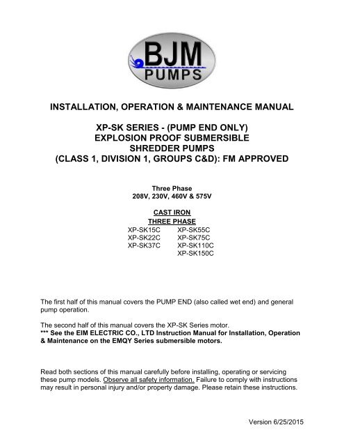
INTRODUCTIONThis Installation, <strong>Operation</strong> and Maintenance manual located in the front half of thismanual only covers the pump end (wet end) of the <strong>XP</strong>-<strong>SK</strong> <strong>Series</strong> pumps.Refer to EIM ELECTRIC CO., LTD Instruction <strong>Manual</strong> located in the second half of thismanual for Installation, <strong>Operation</strong> and Maintenance for the Explosion Proof SubmersibleMotors (EMQY <strong>Series</strong>; FM Approved for Class I, Division 1, Group C & D).This manual provides important information on safety and the proper inspection;disassembly, assembly and testing of the <strong>BJM</strong> <strong>Pumps</strong>® <strong>SK</strong> <strong>Series</strong> Wet End attached toEIM Electric Co., LTD. EMQY <strong>Series</strong> Explosion Proof Submersible Motors. This manualalso contains information to optimize performance and longevity of your <strong>BJM</strong> <strong>Pumps</strong>submersible pump end.The submersible <strong>XP</strong>-<strong>SK</strong> <strong>Series</strong> pumps are designed to pump water with somesolids. The pump and motor housing are made of cast iron (the impeller andsuction are made of chrome iron in pumps with 2, 3 & 5 HP motors). Consultchemical resistance chart for compatibility between pump materials and liquidbefore operating pump.If you have any questions regarding the inspection, disassembly, and assembly ortesting please contact your <strong>BJM</strong> <strong>Pumps</strong> distributor, or <strong>BJM</strong> <strong>Pumps</strong>, LLC.Note: All service work on the FM Approved motor by EIM Electric Co., needs to be doneby an FM Approved repair facility.<strong>BJM</strong> <strong>Pumps</strong>, LLC Phone: 877-256-7867123 Spencer Plain Rd. Phone: 860-399-5937Old Saybrook, CT 06475, USA Fax: 860-399-7784Information, including pump data sheets and performance curves, is also available onour web site: www.bjmpumps.comFor assistance with your electric power source, please contact a certified electrician.Please pay attention to the following alert notifications. They are used to notifyoperators and maintenance personnel to pay special attention to procedures, to avoidcausing damage to the equipment, and to avoid situations that could be dangerous topersonnel.Immediate hazards that WILL result in severe personal injury ordeath. These instructions describe the procedure required and the injury which willresult from failure to follow the procedure.4
Hazards or unsafe practices that COULD result in severe personalinjury or death. These instructions describe the procedure required, and the injury whichcould result from failure to follow the procedure.Hazards or unsafe practices which COULD result in personal injuryor product or property damage. These instructions describe the procedure required andthe possible damage which could result from failure to follow the procedure.SAFETYPump installations are seldom identical. Each installation and application can vary dueto many different factors. It is the owner/service mechanics responsibility to repair,service, and test to ensure that the pump integrity is not compromised according to thismanual.Risk of electric shock – this pump has not been investigated for usein swimming pool areas.Before attempting to open or service the pump:1) Familiarize yourself with this manual & the EIM ELECTRIC CO., LTD Instruction<strong>Manual</strong> for Installation, <strong>Operation</strong> and Maintenance for the EMQY <strong>Series</strong> FM approvedsubmersible pump motor.2) Disconnect the pump power cable to ensure that the pump will remain inoperative.3) Allow the pump to cool if overheated.After the pump has been installed, make sure that the pump and allpiping are secure before operation.Do not lift the pump by the power cable piping or discharge hose.Attach proper lifting equipment to the lifting handle (or lifting rings) fitted to the pump. Donot suspend the pump by the power cable.<strong>Pumps</strong> and related equipment must be installed and operatedaccording to all national, local and industry standards.INSPECTIONReview all safety information before servicing pump.The following are recommended installation practices/procedures for the pump. If thereare questions in regards to your specific application, contact your local <strong>BJM</strong> <strong>Pumps</strong>distributor or <strong>BJM</strong> <strong>Pumps</strong>, LLC.5
Lifting:Attach a rope or lifting chain (not included) to the handle (or lifting rings) on the top ofthe pump.Do not lift the pump by the power cable or discharge hose/piping.Proper lifting equipment (rope/chain) must be used.PRE-INSTALLATION INSPECTION1) Check the pump for damage that may have occurred during shipment.2) Inspect the pump for any cracks, dents, damaged threads, etc.3) Check power cord (and Seal Leak Detector cord, if installed) for any cuts ordamage.4) Check for, and tighten any hardware that appears loose.5) Carefully read all tags, decals and markings on the pump.6) Important: Always verify that the pump nameplate amps, voltage, phase, and HPratings match your control panel and power supply.Record the model numbers and serial numbers from the pumps and control panel onthe front of this instruction manual for future reference. Give it to the owner or affix it tothe control panel when finished with the installation.If anything appears to be abnormal, contact your <strong>BJM</strong> <strong>Pumps</strong> distributor or <strong>BJM</strong><strong>Pumps</strong>, LLC. If damaged, the pump may need to be repaired before use. Do not installor use the pump until appropriate action has been taken.PUMP INSTALLATIONThe Shredder pumps (2 HP) are not designed to pump unscreened solids which couldcontain matter such as bunched paper towels, feminine napkins, tampon applicators,etc. This type of debris can clog the pump & prevent it from operating properly. The<strong>BJM</strong> <strong>Pumps</strong> Shredder <strong>Pumps</strong> (7 ½ HP and larger) are designed to handle unscreenedsewage.POSITIONING THE PUMP<strong>BJM</strong> <strong>Pumps</strong>, <strong>XP</strong>-<strong>SK</strong> <strong>Series</strong> pumps are designed to operate fully or partiallysubmerged. Avoid running the pump dry for extended periods of time. Refer to datasheet for minimum submersion depth for your particular model. Data sheets can beobtained online at www.bjmpumps.com or by calling <strong>BJM</strong> <strong>Pumps</strong>, LLC at 860-399-5937.For minimum submergence requirements, refer to EIM ELECTRIC CO., LTD Instruction<strong>Manual</strong> for Installation, <strong>Operation</strong> and Maintenance for the Explosion Proof SubmersibleMotors (EMQY <strong>Series</strong>; FM Approved for Class I, Division 1, Group C & D).6
Do not run pump dry.Pump liquid should not exceed a maximum temperature of 104°F.Never place the pump on loose or soft ground. The pump may sink, preventingwater from reaching the impeller. Place on a solid surface or suspend the pumpwith a lifting rope/chain.For maximum pumping capacity, use the proper size non-collapsible hose or rigidpiping. A check valve may be installed after the discharge to prevent back flowwhen the pump is shut off (recommended if static head is 30’ or greater).Take stand off of pump when using slide rail. Keep stand and reattach whentransporting or handling the pump.WIRING INSTRUCTIONSElectrical wiring and protection must be in accordance with the National Electrical Codeper NEC articles 500 through 503 for installation in Class I, Division 1, Group C & DHazardous Locations, and any other applicable state and local electrical requirements.For motor specifications, motor technical data, design features, power supply, electricalwiring, operation, inspecting & maintenance, replacing shaft seals, replacing cables,replacing bearings and other parts, repairing, storing and troubleshooting thesubmersible electric motor, refer to EIM ELECTRIC CO., LTD Instruction <strong>Manual</strong> forInstallation, <strong>Operation</strong> and Maintenance for the Explosion Proof Submersible Motors(EMQY <strong>Series</strong>; FM Approved for Class I, Division 1, Group C & D).Note: All service work on the FM approved motor by EIM Electric Co., needs to be doneby an FM Approved repair facility.The <strong>XP</strong>-<strong>SK</strong> <strong>Series</strong> motors have a separate sensor cable for the motor thermal sensorsand Seal Minder. See Seal Minder - Thermal Motor Sensor Switch section in thismanual for proper connection methodPUMP ROTATIONDO NOT PLACE HANDS IN PUMP SUCTION WHILE CHECKINGMOTOR ROTATION. TO DO SO WILL CAUSE SEVERE PERSONAL INJURY.Before installing a pump, check the pump rotation to insure that wiring has beenconnected properly to power source, and that the green lead of power cord (See wiringdiagram), is connected to a valid ground, momentarily energize the pump, observing thedirections of kick back due to starting torque. Rotation is correct if kick back is in theopposite direction of rotation arrow on the pump casing. If rotation is not correct,switching of any two power leads other than ground will provide the proper rotation.7
Two ways to check the correct pump rotation:1. By looking at the impeller; the rotation of the impeller should be counterclockwise as shown in the picture below.2. By looking from the top of the pump. Since the impeller cannot be seen, the bestway to check the rotation is to check the kick back motion of the pump when thepump just starts. The kick back motion of the pump should be counter clockwiseas shown in the picture below.PUMP OPERATIONThis pump is designed to handle dirty water that contains somesolids. Do not attempt to pump any liquids which may damage the pump or endangerpersonnel as a result of pump failure.8
Consult EIM ELELCTRIC Co., LTD. Instruction <strong>Manual</strong> for Installation, <strong>Operation</strong>and Maintenance before connecting, operating or conducting maintenance on theExplosion Proof Submersible Motor.STOPPINGTo stop the pump (manual and automatic mode) turn off the breaker, or turn theelectrical power source off (generator).TROUBLE SHOOTINGDisconnect the electrical power source to the pump BEFOREattempting any type of trouble shooting, service or repair.PUMP WILL NOT RUNRefer to EIM ELECTRIC CO., LTD Instruction <strong>Manual</strong> for Installation, <strong>Operation</strong> andMaintenance for the Explosion Proof Submersible Motors (EMQY <strong>Series</strong>; FM Approvedfor Class I, Division 1, Group C & D).PUMP RUNS BUT DOES NOT DELIVER RATED CAPACITY1. Discharge line clogged, restricted or hose kinked. Check discharge hose/pipe.2. Worn impeller and/or suction cover. Inspect and replace as necessary.3. Pump overloaded due to liquid pumped being too thick.4. Pumping air. Check liquid level and position of pump.5. Excessive voltage drops due to long cables.6. Pump running backwards, check rotation.SERVICING YOUR SUBMERSIBLE PUMPPump should be disconnected from the electric power supply before proceeding to doany service or maintenance.Service on submersible electric motor should only be performed by a qualifiedelectrician. Refer to EIM ELECTRIC CO., LTD Instruction <strong>Manual</strong> for Installation,<strong>Operation</strong> and Maintenance for the Explosion Proof Submersible Motors (EMQY <strong>Series</strong>;FM Approved for Class I, Division 1, Group C & D).MAINTAINING YOUR PUMPPump should be disconnected from the electric power supply before proceedingto do any service or maintenance.Pump should be inspected at regular intervals.9
More frequent inspections are required if the pump is used in a harshenvironment.Preventative maintenance should be performed to reduce the chance ofpremature failure.Worn impellers and lip seals should be replaced.Cut or cracked power cords must be replaced. (Never operate a pump with acut, cracked or damaged power cord.)Maintenance should always be done when taking a pump out of service beforestorage.The impeller to suction cover clearance should be adjusted to between 0.01” to0.02” for optimal cutting of the shredder. Shim kits are available if adjustment isrequired.1) Clean pump of dirt and other build up.2) Check condition of oil around the shaft seals.3) Check hydraulic parts: check for wear.4) Inspect power cable. Make sure that it is free of nicks or cuts.CHANGING SEAL OILRefer to EIM ELECTRIC CO., LTD Instruction <strong>Manual</strong> for Installation, <strong>Operation</strong> andMaintenance for the Explosion Proof Submersible Motors (EMQY <strong>Series</strong>; FM Approvedfor Class I, Division 1, Group C & D).10
E<strong>XP</strong>LODED VIEW OF <strong>XP</strong>-<strong>SK</strong>15C (2HP)<strong>BJM</strong> WET END ASSEMBLY FOR EIM FM MOTOR11
E<strong>XP</strong>LODED VIEW OF <strong>XP</strong>-<strong>SK</strong>22C, <strong>XP</strong>-<strong>SK</strong>37C (3 & 5HP)<strong>BJM</strong> WET END ASSEMBLY FOR EIM FM MOTOR12
E<strong>XP</strong>LODED VIEW OF <strong>XP</strong>-<strong>SK</strong>55C, <strong>XP</strong>-<strong>SK</strong>75C<strong>BJM</strong> WET END ASSEMBLY FOR EIM FM MOTOR13
E<strong>XP</strong>LODED VIEW OF <strong>XP</strong>-<strong>SK</strong>110C, <strong>XP</strong>-<strong>SK</strong>150C<strong>BJM</strong> WET END ASSEMBLY FOR EIM FM MOTOR14
<strong>XP</strong>-<strong>SK</strong> SERIES PARTS LISTPump Model <strong>XP</strong>-<strong>SK</strong>15C <strong>XP</strong>-<strong>SK</strong>22C <strong>XP</strong>-<strong>SK</strong>37C <strong>XP</strong>-<strong>SK</strong>55C <strong>XP</strong>-<strong>SK</strong>75C <strong>XP</strong>-<strong>SK</strong>110C <strong>XP</strong>-<strong>SK</strong>150CPos. No. Part Description Item # Item # Item # Item # Item # Item # Item #01-2 Stand Only 202858 202850 202855 201998 201998 202000 20200002 Suction Cover, Cast Iron - - - 202880 202880 202882 20288202 Suction Cover, Hi-Chrome 202046 202047 202048 - - - -03 Impeller Nut 202894 202894 202894 202897 202897 202897 2028973 Upper Ball Bearing (See EIM <strong>Manual</strong>) 200959 200959 200959 200968 200968 200968 20096204 Impeller Washer 202907 202907 202907 202917 202917 202917 20291705 Impeller, Cast Iron 202961 202964 202967 202136 202138 202945 20294705 Impeller, Hi-Chrome 202960 202963 202966 - - - -06 Impeller Key 202140 202140 202140 202146 202146 202146 2029876 Stator 208V (See EIM <strong>Manual</strong>) 200969 200971 200973 - - - -6 Stator 230V (See EIM <strong>Manual</strong>) 200969 200971 200973 200975 200977 200979 2009816 Stator 460V (See EIM <strong>Manual</strong>) 200969 200971 200973 200975 200977 200979 2009816 Stator 575V (See EIM <strong>Manual</strong>) 200970 200972 200974 200976 200978 200980 20098207 Pump Housing 203008 203011 203014 203024 203024 203027 2030277 & 8 Rotor/Shaft Assy. (See EIM <strong>Manual</strong>) 200983 200984 200985 200986 200987 200988 20098912L Mating Plate / Oil Chamber CoverSee the EIM Electric Co., LTD I O & M <strong>Manual</strong>09 Lip Seal Buna-N 203051 202234 202234 202238 202238 202238 20223809 Lip Seal FKM (Optional) 202232 202235 202235 202243 202243 202243 2022439 Lower Ball Bearing (See EIM <strong>Manual</strong>) 200961 200961 200961 200494 200949 200495 20049610 Mechanical Seal - Buna (See EIM <strong>Manual</strong>) 200332 200332 200332 200333 200333 200333 20033410 Mechanical Seal - FKM** (See EIM <strong>Manual</strong>) 200338 200338 200338 200339 200339 200339 20034038 Discharge Nipple 3" 202534 202534 202534 - - - -38E Discharge Elbow 202558 202558 202558 3/833 202572 203187 3734C38E-1 Gasket, Discharge Elbow Buna-N 203208 203208 203208 203210 203210 202663 20266338E-1 Gasket, Discharge Elbow FKM(Optional) 203209 203209 203209 203211 203211 202664 20266438F Discharge Flange 3" 202545 202545 202545 - - - -38F Discharge Flange 4" - 202552 202552 202575 202575 - -38F Discharge Flange 6" ANSI Slip Weld - - - - - 202548 20254838F-1 Gasket, Discharge Flange Buna-N 202659 202659 202659 202661 202661 202663 20266338F-1 Gasket, Discharge Flange FKM (Optional) 202660 202660 202660 202662 202662 202664 20266450-01-2 Bolt for Strainer/Stand 203228 203228 203228 203236 203236 203279 20327915
50-02 Bolt for Suction Cover 203228 203228 203228 203236 203236 203279 20327950-07 Bolt for Mating Plate to Volute 203229 203229 203229 203236 203236 - -50-11V Air Release Valve - - - 202707 202707 202707 20270750-38E Bolt for Discharge Elbow 203255 203255 203255 203276 203276 203278 20327850-38F Bolt for Discharge Flange 203289 203289 203253 203277 203277 203278 20327849 Bell Mouth (See EIM <strong>Manual</strong>) Pwr Cable Assy. Pwr Cable Assy. Pwr Cable Assy. Pwr Cable Assy. Pwr Cable Assy. Pwr Cable Assy. Pwr Cable Assy.49-SN Stud & Nut (See EIM <strong>Manual</strong>) Pwr Cable Assy. Pwr Cable Assy. Pwr Cable Assy. Pwr Cable Assy. Pwr Cable Assy. Pwr Cable Assy. Pwr Cable Assy.50 Cable Bushing (See EIM <strong>Manual</strong>) Pwr Cable Assy. Pwr Cable Assy. Pwr Cable Assy. Pwr Cable Assy. Pwr Cable Assy. Pwr Cable Assy. Pwr Cable Assy.54 Cable (See EIM <strong>Manual</strong>) Pwr Cable Assy. Pwr Cable Assy. Pwr Cable Assy. Pwr Cable Assy. Pwr Cable Assy. Pwr Cable Assy. Pwr Cable Assy.55 Cable clamp (See EIM <strong>Manual</strong>) Pwr Cable Assy. Pwr Cable Assy. Pwr Cable Assy. Pwr Cable Assy. Pwr Cable Assy. Pwr Cable Assy. Pwr Cable Assy.55-B Bolt (See EIM <strong>Manual</strong>) Pwr Cable Assy. Pwr Cable Assy. Pwr Cable Assy. Pwr Cable Assy. Pwr Cable Assy. Pwr Cable Assy. Pwr Cable Assy.Pwr Cable Assy.208VPwr Cable Assy.230VPwr Cable Assy.460V200998 200998 200999 200999 - -200998 200998 200999 200999 201000 201000 -200998 200998 200998 200998 200998 200999 201001200998 200998 200998 200998 200998 200999 201001Pwr Cable Assy.575V49 Bell Mouth (See EIM <strong>Manual</strong>) Pwr Cable Kit Pwr Cable Kit Pwr Cable Kit Pwr Cable Kit Pwr Cable Kit Pwr Cable Kit Pwr Cable Kit49-SN Stud & Nut (See EIM <strong>Manual</strong>) Pwr Cable Kit Pwr Cable Kit Pwr Cable Kit Pwr Cable Kit Pwr Cable Kit Pwr Cable Kit Pwr Cable Kit50 Cable Bushing (See EIM <strong>Manual</strong>) Pwr Cable Kit Pwr Cable Kit Pwr Cable Kit Pwr Cable Kit Pwr Cable Kit Pwr Cable Kit Pwr Cable Kit55-B Bolt (See EIM <strong>Manual</strong>) Pwr Cable Kit Pwr Cable Kit Pwr Cable Kit Pwr Cable Kit Pwr Cable Kit Pwr Cable Kit Pwr Cable Kit55 Cable clamp (See EIM <strong>Manual</strong>) Pwr Cable Kit Pwr Cable Kit Pwr Cable Kit Pwr Cable Kit Pwr Cable Kit Pwr Cable Kit Pwr Cable KitPwr Cable Kit 208VPwr Cable Kit 230VPwr Cable Kit 460V200233 200233 200291 200291 - - -200233 200233 200291 200291 200328 200328 -200233 200233 200233 200233 200233 200291 200330200233 200233 200233 200233 200233 200291 200330Pwr Cable Kit 575V2-R O-Ring (See EIM <strong>Manual</strong>) O-Ring Kit O-Ring Kit O-Ring Kit O-Ring Kit O-Ring Kit O-Ring Kit O-Ring Kit5-R1 O-Ring (See EIM <strong>Manual</strong>) O-Ring Kit O-Ring Kit O-Ring Kit O-Ring Kit O-Ring Kit O-Ring Kit O-Ring Kit5-R2 O-Ring (See EIM <strong>Manual</strong>) O-Ring Kit O-Ring Kit O-Ring Kit O-Ring Kit O-Ring Kit O-Ring Kit O-Ring Kit12U-R O-Ring (See EIM <strong>Manual</strong>) O-Ring Kit O-Ring Kit O-Ring Kit O-Ring Kit O-Ring Kit O-Ring Kit O-Ring Kit28-P O-Ring (See EIM <strong>Manual</strong>) O-Ring Kit O-Ring Kit O-Ring Kit O-Ring Kit O-Ring Kit O-Ring Kit O-Ring KitO-Ring Kit-Buna NO-Ring Kit-FKM (Optional)***See pages 32-39 for parts position numbers***200335 200335 200335 200336 200336 204167 200337200341 200341 200341 200342 200342 204168 20034316
<strong>XP</strong>-<strong>SK</strong> DIMENSIONAL DRAWING17
SEAL MINDER® - THERMAL MOTOR SENSOR SWITCHSeal Minder:Also known as a seal failure circuit (or moisture detection circuit) is designed to inform the pumpoperator that there is moisture within the oil chamber. This early warning can allow the operator toschedule repair & inspection on the pump. The Seal Minder sensor probe is inside the oil chamber.(The oil chamber houses the mechanical seals that are cooled & lubricated by oil). The Seal Minder,when properly connected to a control panel, can help indicate seal failure. The Seal Minder cordrequires a seal fail circuit in control panel for warning signal.Along, with the Seal Minder, the <strong>XP</strong>-<strong>SK</strong> <strong>Series</strong> pumps also feature thermal temperature sensorswitches that are imbedded into the motor stator windings. Two switches are imbedded into the statorwindings and wired in series. The leads are connected to the pump control panel through the sensorcable. If the windings would see a temperature above 300 degrees F, then the switch(s) would openand cut power to the pump. Once the temperature dropped below 300 degrees F, the switch(s) wouldreset, and the pump would be returned to a state of operation. This feature is designed to preventdamage to the stator winding and allow for longer pump life.The sensor cable consists of four leads, two are connected to the Seal Minder, and two areconnected to the thermal sensor switches located in the stator windings. These four leads run to thepump control panel and connect to the proper connections points for seal alarm and thermal cut off.The G2(Green) and K(Red) wires are for the Seal Minder connections and the thermal sensors willbe connected to the m(White) and N(Black) wires. The three phase automatic wiring diagram shownearlier in the manual will give a guide to the connections in the control panel. The manual for thecontrol panel should be consulted for the exact connections.The sensor cable with Seal Minder and thermal sensor switch connections is standard on all <strong>XP</strong>-<strong>SK</strong><strong>Series</strong> pumps. The proper replacement part can be found parts list found in this manual. <strong>BJM</strong> <strong>Pumps</strong>,can supply a control with the Seal Minder and Thermal sensor switch option. Separate stand aloneSeal Minder alarm panels are also available. Consult your <strong>BJM</strong> <strong>Pumps</strong> representative for partnumbers and ordering details. <strong>BJM</strong> <strong>Pumps</strong> requires the Seal Minder and thermal sensorswitches be used. Failure to connect or misuse of these devices will void warranty.18
<strong>BJM</strong> PUMPS, LLC<strong>BJM</strong> PUMPS, LLC123 Spencer Plain RoadOld Saybrook, CT 06475, U.S.A.WARRANTY AND LIMITATION OF LIABILITYUnless otherwise expressly authorized in writing, specifying a longer or shorter period, <strong>BJM</strong> <strong>Pumps</strong>,LLCwarrants for a period of eighteen (18) months from the date of shipment from the Point of Shipment, or one (1)year from the date of installation, whichever occurs first, that all products or parts thereof furnished by <strong>BJM</strong><strong>Pumps</strong>,LLC under the brand name <strong>BJM</strong> <strong>Pumps</strong>, hereinafter referred to as the “Product” are free from defectsin materials and workmanship and conform to the applicable specification.<strong>BJM</strong> <strong>Pumps</strong>,LLC’s liability for any breach of this warranty shall be limited solely to replacement or repair, at thesole option of <strong>BJM</strong> <strong>Pumps</strong>,LLC, of any part or parts of the Product found to be defective during the warrantyperiod, provided the Product is properly installed and is being used as originally intended. Any breach of thiswarranty must be reported to <strong>BJM</strong> <strong>Pumps</strong>,LLC or <strong>BJM</strong> <strong>Pumps</strong>,LLC’s authorized service representative withinthe aforementioned warranty period, and defective Product or parts thereof must be shipped to <strong>BJM</strong><strong>Pumps</strong>,LLC or <strong>BJM</strong> <strong>Pumps</strong>,LLC’s authorized representative, transportation charges prepaid. Any costassociated with removal or installation of a defective Product or part is excluded.IT IS E<strong>XP</strong>RESSLY AGREED THAT THIS SHALL BE THE SOLE AND EXCLUSIVE REMEDY OF <strong>BJM</strong>PUMPS, LLC’S DISTRIBUTORS AND CUSTOMERS. UNDER NO CIRCUMSTANCES SHALL <strong>BJM</strong> PUMPS,LLC BE LIABLE FOR ANY COSTS, LOSS, E<strong>XP</strong>ENSE, DAMAGES, SPECIAL DAMAGES, INCIDENTALDAMAGES OR CONSEQUENTIAL DAMAGES ARISING DIRECTLY OR INDIRECTLY FROM THE DESIGN,MANUFACTURE, SALE, USE OR REPAIR OF THE PRODUCT, WHETHER BASED ON WARRANTY,CONTRACT, NEGLIGENCE, OR STRICT LIABILITY. IN NO EVENT WILL LIABILITY EXCEED THEPURCHASE PRICE OF THE PRODUCT.THE WARRANTY AND LIMITS OF LIABILITY CONTAINED HEREIN ARE IN LIEU OF ALL OTHERWARRANTIES AND LIABILITIES, E<strong>XP</strong>RESSED OR IMPLIED. ALL IMPLIED WARRANTIES OFMERCHANTABILITY AND FITNESS FOR A PARTICULAR PURPOSE ARE HEREBY DISCLAIMED BY <strong>BJM</strong>PUMPS, LLC AND EXCLUDED FROM THIS WARRANTY.<strong>BJM</strong> <strong>Pumps</strong>,LLC neither assumes, nor authorizes any person to assume for it, any other warranty obligation inconnection with the sale of the Product. This warranty shall not apply to any Product or parts of Product whichhave (a) been repaired or altered outside of <strong>BJM</strong> <strong>Pumps</strong>,LLC’s facilities unless such repair was authorized inadvance by <strong>BJM</strong> <strong>Pumps</strong>,LLC or by its authorized representative; or (b) have been subject to misuse,negligence or accident; or (c) have been used in a manner contrary to <strong>BJM</strong> <strong>Pumps</strong>,LLC’s instruction.In any case of products not manufactured and sold under the <strong>BJM</strong> <strong>Pumps</strong>,LLC brand name, there is nowarranty from <strong>BJM</strong> <strong>Pumps</strong>,LLC; however <strong>BJM</strong> <strong>Pumps</strong>,LLC will extend any warranty received from <strong>BJM</strong><strong>Pumps</strong>,LLC’s supplier of such products.21
START-UP REPORT FORMSTART-UP REPORT FORMThis form is designed to record the initial installation, and to serve as a guide for troubleshooting at alater date (if needed).<strong>BJM</strong> <strong>Pumps</strong>, LLC123 Spencer Plain RoadOld Saybrook, CT. 06475Pump Owner’s NameLocation of InstallationDate of Installation:Dealer Dealer Phone ( )Date of PurchaseModelSerial NoVoltage Phase Hertz HPDoes impeller turn freely by hand? Yes NoCondition of Equipment New Good Fair PoorCondition of Cable Jacket New Good Fair PoorRotation: Direction of Impeller Rotation (viewed from bottom)(Use C/W for clockwise, CC/W for counterclockwise):Resistance of cable and Pump Motor (measured at pump control)Red-Black ohms Red-White ohms White-Black ohmsResistance of ground circuit between control panel and outside of pumpsOhmsMEG OHM CHECK OF INSULATIONRed to ground White to ground Black to groundCondition of location at start-up Dry Wet MuddyWas equipment storedIf YES, length of storage:Yes No.Liquid being pumpDebris in bottom of station? Yes No
START-UP REPORT FORMAre guide rails vertical? Yes NoIs base elbow installed level? Yes NoLiquid level controls: ModelIs control installed away from turbulence? Yes NoFloat <strong>Operation</strong> CheckTip lowest float (stop float), all pumps should remain off.Tip second float (and stop float), one pump comes on.Tip third float (and stop float), both pumps on (alarm on simplex).Tip fourth float (and stop float), high level alarm on (omit on simplex).Check here if using manual on/off only.Does liquid level ever drop below volute top? Yes NoControl Panel MFG & model no.Number of pumps operated by control panelNOTE: At no time should hole be made in top of control panel, unless proper sealingdevices are utilized.Short Circuit protection:Type:Number and size of short circuit device(s)Amp rating:Overload type: Size: Amp rating:Do protective devices comply with pump motor amprating?Are all pump connections tight? Yes NoYesNoIs the interior of the panel dry?Electrical readingsYes NoIf No, correct moisture problem.SINGLE PHASEVoltage supply at panel line connection, pump off L1 L2Voltage supply at panel line connection, pump on L1 L2Amperage load connection, pump on L1 L2THREE PHASEVoltage supply at panel line connection, pump offL1-L2 L2-L3 L3-L1Voltage supply at panel line connection, pump on
START-UP REPORT FORML1-L2 L2-L3 L3-L1Amperage load connection, pump onL1 L2 L3FINAL CHECKIs pump secured properly? Yes NoWas pump checked for leaks? Yes NoDo check valves operate properly? Yes NoFlow: Do pumps appear to operate at proper rate? Yes NoComments:Noise level: Acceptable UnacceptableInstalled by:Company:Person:Date:
NOTES:
123 Spencer Plain Road • PO Box 1138 • Old Saybrook, CT 06475, USA• Phone: (860) 399-5937 • Fax: (860) 399-7784Email: sales@bjmcorp.com • Web Site: www.bjmpumps.com<strong>BJM</strong> <strong>Pumps</strong> is a registered trademark of <strong>BJM</strong> <strong>Pumps</strong>, LLC.Copyright © 2009-2013 <strong>BJM</strong> <strong>Pumps</strong>, LLC. All rights reserved.