PGV-Series Operation Manual - BJM Pumps
PGV-Series Operation Manual - BJM Pumps
PGV-Series Operation Manual - BJM Pumps

Create successful ePaper yourself
Turn your PDF publications into a flip-book with our unique Google optimized e-Paper software.
INSTALLATION, OPERATION & MAINTENANCE MANUAL<strong>PGV</strong> SERIESVERTICAL DISCHARGEHorizontal Electric Submersible <strong>Pumps</strong>CAST IRONThree Phase460V<strong>PGV</strong> 55<strong>PGV</strong> 75<strong>PGV</strong> 110Three Phase460V<strong>PGV</strong> 220Read this manual carefully before installing, operating or servicing these pump models.UObserve all safety information.U Failure to comply with instructions may result in personalinjury and/or property damage. Please retain these instructions.Version 4/10/2013
TABLE OF CONTENTSINTRODUCTION ....................................................................................................................................................... 4SAFETY ....................................................................................................................................................................... 5INSPECTION .............................................................................................................................................................. 6TRANSPORTATION ................................................................................................................................................. 6RECEIVING ................................................................................................................................................................ 6PRE-INSTALLATION INSPECTION ................................................................................................................. 6INSTALLATION: ....................................................................................................................................................... 7WIRING: ...................................................................................................................................................................... 8INTENDED METHODS OF CONNECTION .......................................................................................................... 9THREE PHASE WIRING INSTRUCTION ......................................................................................................... 9PUMP OPERATION ................................................................................................................................................ 11MAINTENANCE AND INSPECTION ................................................................................................................... 12DISPOSAL OF PUMP .............................................................................................................................................. 13TROUBLE SHOOTING ........................................................................................................................................... 13ASSEMBLING: ......................................................................................................................................................... 18SECTIONAL VIEW OF <strong>PGV</strong>55, 75 & 110............................................................................................................. 19SECTIONAL VIEW OF <strong>PGV</strong>220 ............................................................................................................................ 20<strong>PGV</strong> SERIES PARTS LIST ..................................................................................................................................... 21WARRANTY AND LIMITATION OF LIABILITY ............................................................................................. 23START-UP REPORT FORM .................................................................................................................................. 24NOTES: ...................................................................................................................................................................... 27
INTRODUCTIONThis Installation, <strong>Operation</strong> and Maintenance manual provides important information onsafety and the proper inspection, disassembly, assembly and testing of the <strong>BJM</strong><strong>Pumps</strong>® <strong>PGV</strong> <strong>Series</strong> horizontal submersible pump. This manual also containsinformation to optimize performance and longevity of your <strong>BJM</strong> <strong>Pumps</strong> submersiblepump.The submersible <strong>PGV</strong> <strong>Series</strong> pumps are designed to pump municipal; andindustrial wastewater. The <strong>PGV</strong> <strong>Series</strong> pumps are not explosion-proof. They arenot designed to pump volatile or flammable liquids.Note: Consult chemical resistance chart for compatibility between pumpmaterials and liquid before operating pump.If you have any questions regarding the inspection, disassembly, assembly or testingplease contact your <strong>BJM</strong> <strong>Pumps</strong> distributor, or <strong>BJM</strong> <strong>Pumps</strong>, LLC.<strong>BJM</strong> <strong>Pumps</strong>, LLC123 Spencer Plain Rd.Old Saybrook, CT 06475, USAFax: 860-399-7784Phone: 877-256-7867Phone: 860-399-5937Information, including pump data sheets and performance curves, is also available onour web site: HUwww.bjmpumps.comUFor assistance with your electric power source, please contact a certified electrician.Please pay attention to the following alert notifications. They are used to notifyoperators and maintenance personnel to pay special attention to procedures, to avoidcausing damage to the equipment, and to avoid situations that could be dangerous topersonnel.NOTE: Instructions to aid in installation, operation, and maintenance or whichclarify a procedure.Immediate hazards that WILL result in severe personal injury ordeath. These instructions describe the procedure required and the injury which willresult from failure to follow the procedure.Hazards or unsafe practices that COULD result in severe personalinjury or death. These instructions describe the procedure required, and the injury whichcould result from failure to follow the procedure.Hazards or unsafe practices which COULD result in personal injuryor product or property damage. These instructions describe the procedure required andthe possible damage which could result from failure to follow the procedure.4
SAFETYPump installations are seldom identical. Each installation and application can vary dueto many different factors. It is the owner/service mechanics responsibility to repair,service, and test to ensure that the pump integrity is not compromised according to thismanual.Risk of electric shock – this pump has not been investigated for usein swimming pool areas.Do not pump flammable, inflammable or volatile liquids. UDeathor serious injury will result.Before attempting to open or service the pump:1) Familiarize yourself with this manual.2) Unplug or disconnect the pump power cable to ensure that the pump will remaininoperative.3) Allow the pump to cool if overheated.Do not operate the pump with a worn or damaged electric powercable. Death or serious injury could occur.Never attempt to alter the length or repair any power cable with asplice. The pump motor and pump motor and cable must be completely waterproof.Damage to the pump or personal injury may result from alterations.After the pump has been installed, make sure that the pump and allpiping are secure before operation.Do not lift the pump by the power cable piping or discharge hose.Attach proper lifting equipment to the lifting handle (or lifting rings) fitted to the pump. Donot suspend the pump by the power cable.Obtain the services of a qualified electrician to troubleshoot, testand/or service the electrical components of this pump.<strong>Pumps</strong> and related equipment must be installed and operatedaccording to all national, local and industry standards.Make sure to ground the terminal (green) exclusive for grounding in accordance withlocal electrical codes and internal regulations.5
Transportation, installation, wiring, operation, maintenance, and inspection should beperformed only by authorized and qualified personnel.INSPECTIONReview all safety information before servicing pump.• Do not exceed rated specifications for use; a submersible pump shouldnot be used on land. Failure to observe this caution may cause electricshock, injury to a person or damage to the product.• Do not use pump if damaged in anyway.• Any modifications of the product made by the user shall void guarantee.• Do not remove the nameplate.TRANSPORTATIONDuring transport, care must be taken to avoid dropping or overturning the pump.Failure to observe this caution may cause injury or damage to the product.When lifting the pump, be sure to lift it using its lifting rings or handle.• Do not lift a pump with machine connected, using only the lifting rings ofthe pump. Failure to observe this caution may cause injury or damage tothe product.• Do not lift by cables. Failure to observe this caution may cause injury ordamage to the product.RECEIVINGOpen packing after confirming that pump is right side up. Failure to observe this cautionmay cause injury.Verify that the received pump is the one you ordered. Installing the wrong product cancause unwanted results, and damage to the product.The following are recommended installation practices/procedures for the pump. If thereare questions in regards to your specific application, contact your local <strong>BJM</strong> <strong>Pumps</strong>distributor or <strong>BJM</strong> <strong>Pumps</strong>, LLC.PRE-INSTALLATION INSPECTION1) Check the pump for damage that may have occurred during shipment.2) Inspect the pump for any cracks, dents, damaged threads, etc.3) Check power cord (and seal minder cord, if installed) for any cuts or damage.4) Check for, and tighten any hardware that appears loose.6
5) Carefully read all tags, decals and markings on the pump.6) Important: Always verify that the pump nameplate, amps, voltage, phase, andHP ratings match your control panel and power supply.Warranty does not cover damage caused by connecting pumps and controls to anincorrect power source (voltage/phase supply). Record the model numbers and serialnumbers from the pumps and control panel on the front of this instruction manual forfuture reference. Give it to the owner or affix it to the control panel when finished withthe installation.If anything appears to be abnormal, contact your <strong>BJM</strong> <strong>Pumps</strong> distributor or <strong>BJM</strong><strong>Pumps</strong>, LLC. If damaged, the pump may need to be repaired before use. Do not installor use the pump until appropriate action has been taken.INSTALLATION:1. Inspect each part/component to verify that it is free of damage and imperfections.2. Do not lift or move the pump by the power cable. Use the lifting handle or eyebolt attachment to support movement of the pump.3. Never place the pump on loose or soft ground. The pump may sink, preventingwater from reaching the impeller. Place on a solid surface or suspended thepump with a lifting rope/chain. The pump can pass solids that are compatible withthe suction/agitator opening size (see technical data sheet).4. Running the pump dry for extended periods of time may damage the seals andover-heat the motor. Do not run the pump below the recommended operatinglevel (see technical data sheet).5. Pumping liquid should not exceed a maximum temperature of 104°F.Remove foreign matter such as concrete clods or stones after installing the pump in thetank. Failure to observe this caution may cause damage to the impeller or casing, orblock the intake port.7
WIRING:Risk of electric shock. <strong>PGV</strong> <strong>Series</strong> pump models do not comewith electric plug connectors. To reduce the risk of electric shock, be certain that it isconnected only to a properly grounded, grounding-type receptacle.• Perform wiring conforming to National Electrical Code or to local electricalcodes. Failure to observe this caution may cause fire or damage to theproduct.• Make sure that the pump is rotating in the correct direction. Forwardrotation creates more pressure and discharge power than reverse rotation.• For built-in automatic level control pump never take the float bracket to liftthe pump or pull the lead. Failure to observe this caution may cause injuryor damage to the product.Do not alter the length or repair any power cable with a splice. Thepump motor and cable must be completely waterproof. Damage to the pump orpersonal injury may result from alterations.1. Voltage and frequency check- check whether the supply voltage and frequencymeet those indicated on the pump name plate.2. Power connection- connect three wires U (red), V (white) and W (black) of thepower cable of the pump to a power supply unit at site.a. Terminal E9 (green) is for ground use. Connect a grounding wire to thisterminal pursuant to the relevant law.b. Also, provide electric leakage breaker.3. Allowable cable length- keep voltage drop of the power cable with in 5% of thespecified voltage. Table 1 shows the allowable cable length subject to 5%voltage down. (In case of 200V class)a. The allowable cable length for the specified voltage 400V is four times thevalues shown in Table-1.Nominal sectional area of cabtyre cable(mm)3.5 5.5 8 14 22 30 38Allowable current of cabtyre cable (Amps) 28 36 44 62 83 98<strong>PGV</strong>55 50 75 105 185 290 410Pump model and motor output<strong>PGV</strong>75 55 80 140 215 305<strong>PGV</strong>110 95 155 210 240<strong>PGV</strong>220 110 130Table 1 Allowable cable length (m)8
INTENDED METHODS OF CONNECTION<strong>BJM</strong> <strong>Pumps</strong> has been evaluated for use with water or water based solutions. Pleasecontact the manufacturer for additional information.THREE PHASE WIRING INSTRUCTIONFOR YOUR PROTECTION, ALWAYS DISCONNECT PUMPFROM ITS POWER SOURCE BEFORE HANDLING.“Risk of electrical shock” Do not remove power supply cord andstrain relief or connect conduit directly to the pump.Installation and checking of electrical circuits and hardware shouldbe performed by a qualified licensed electrician.To automatically operate a non-automatic three phase pump, a control panel isrequired. Follow the instructions provided with the panel to wire the system for automaticthree phase pumps see automatic three phase wiring diagram.Before installing a pump, check the pump rotation to insure that wiring has beenconnected properly to power source, and that the green lead of power cord (See wiringdiagram), is connected to a valid ground, momentarily energize the pump, observing thedirections of kick back due to starting torque. Rotation is correct if kick back is in theopposite direction of rotation arrow on the pump casing. If rotation is not correct,switching of any two power leads other than ground will provide the proper rotation.9
<strong>BJM</strong> <strong>Pumps</strong> three phase pumps have integral motor overload protection. <strong>BJM</strong>recommends that all three phase pumps using a motor starting device also incorporatemotor overload protection. <strong>Pumps</strong> must be installed in accordance with the NationalElectrical Code and all applicable local codes and ordinances. <strong>Pumps</strong> are not to beinstalled in locations classified as hazardous in accordance with National ElectricalCode, ANSI/NFPA 70.Connect pump to a junction box, outlet box, control box, enclosure with a wiringcompartment that meets NEC and local codes in volume, and applicable fittings forsupply connection. The provision for supply connection shall reduce the risk of waterentry during temporary, limited submersion and shall comply with the applicablerequirements of the Standard for Enclosures for Electrical Equipment, UL 50, or thestandard for Metallic Outlet Boxes, UL 514A, and the standard for Motor-OperatedWater <strong>Pumps</strong>. UL 778.4. Pump revolution direction- the correct revolution direction of the impeller iscounterclockwise viewing from the strainer side as shown in Fig. 1.Figure 1rotation.Safety glasses must be worn when visually checking impellerSwitch ON the pump in inching mode and look into the impeller from the strainer side tocheck its normal rotational direction, just before complete stop of the impeller.Checking before piping connection can be made by looking into the impeller from thedischarge pipe side.If the rotational direction of the impeller is reverse upon checking, interchange optionaltwo wires of the power cable.10
PUMP OPERATIONNever get near or touch the suction port and discharge portsduring operation. Failure to observe this warning may cause injury by beingcaught in a rotating part such as impeller. Do not put fingers in strainer or pumpintake.• Never operate the pump under minimum water levels during continuousoperation• When changes in current and pressure occur during operation, check forabnormalities such as overload due to entrance of foreign matter.• Immediately stop operation upon detection of any malfunction. Failure toobserve this caution may cause electric shock, injury or fire.• Make sure to turn OFF the power source at power failure. Failure toobserve this caution may cause injury.• Make sure to maintain the specified liquid temperature. For hightemperatureliquid specification, refer to the catalogue. Failure to observethis caution may cause injury.• For pumps with cutting mechanism, never rotate in reverse. Failure toobserve this caution may cause burn-out of motor and injury.This pump is designed to handle dirty water that contains somesolids. It is not designed to pump volatile or flammable liquids. Do not attempt to pumpany liquids which may damage the pump or endanger personnel as a result of pumpfailure.Do not operate this pump where explosive vapors orflammable material exist. Death or Serious injury will result.1. Change of running condition depending on water level. If the suction water levelcomes down near “LEVEL 1”, air will be suctioned with generated vortex andconsequently the pump is put in water-roaring run condition, which continues untilthe water level reaches next “LEVEL 2”. (Refer to Fig. 2)11
Figure 2If the water level is below “LEVEL 2”, the suctioned air rate will increase; causingpumping failure of the pump and finally the pump is put in no-load running condition.In case of this pump, however, unlike vertical submersible pumps the motor frame ofthis pump is submerged in the range from “LEVEL 1” to “LEVEL 2” so that the motor iseffectively cooled. When the water level is below “LEVEL 2”, the motor frame exposesto the atmosphere and consequently the cooling effect comes down, but it is safety withlow temperature because of its non-load run condition.2. Voltage check - during pump running; sometimes measure the power voltage tocheck that it is within the range of 95% - 105% of the specified voltage.3. Attention to pumping up of high density water where sand, slurry and other solidsare much contained in the pumping of water, the shaft power increases withincreasing mixture density of solids and the motor is eventually overloaded. (Specialtechnical instructions on this matter are available. It will be furnished upon request).In such case, read the ammeter to monitor the electric current of the motor and adjustthe pump location.MAINTENANCE AND INSPECTIONTo service or repair your pump, please contact your local <strong>BJM</strong> <strong>Pumps</strong> distributor.Service should only be performed by a qualified electrician.Insulation resistance of 1MΩ or greater, or unstable values with sudden drops indicatespotential malfunction and should be investigated.Never touch terminals when measuring insulation resistance. Failure to observe thiscaution may cause electric shock.• Pump should be disconnected from the electric power supply before proceedingto do any service or maintenance.12
• Pump should be inspected at regular intervals.• More frequent inspections are required if the pump is used in a harshenvironment.• Preventative maintenance should be performed to reduce the chance ofpremature failure.• Worn impellers and lip seals should be replaced.• Cut or cracked power cords must be replaced. (Never operate a pump with acut, cracked or damaged power cord.)• Seal oil should be checked once per year.• Maintenance should always be done when taking a pump out of service beforestorage.DISPOSAL OF PUMPWhen disposing a pump, treat it as a general industrial waste, abiding by federal, stateand local regulations.TROUBLE SHOOTINGDisconnect the power source to the pump BEFORE attemptingany type of trouble shooting, service or repair.Warning: Pump will restart automatically when motor over-heat protection switchcools.Repair and assembly should be performed by qualified personnel only. Failure toobserve this caution may cause electric shock, injury or fire.1) Pump fails to run (no running noise)No electric current in powerdistribution lineNo electric current in pumpcablePower switch in OFF. Or 2 phase or more in opencondition due to fault of the switch<strong>Operation</strong> switch in OFF. Or 2 phase or more inopen condition due to fault of the switch. Possiblecauses: Contact failure of switch, fusedisconnection, reset-missing of over current relayInspect and repair.13
2) Pump fails to run, or runs but fails to reach full speed.Voltage drop in power line Check whether or not the power voltage is normalSingle-phase run Power switch, operation switch or pump cablewith either one wire opened or disconnected.Inspect and repair or replace.Stuck impeller RepairMotor troubleCauses: Insulation fault, interlayer and interphaseshort-circuit, single-phase disconnectionInspect and repair.3) Pump runs at full speed, but produces abnormal noise mechanically.Broken impeller ReplaceWorn or damage bearing ReplaceLow level running Not harmful, but less pumping rate and lowefficiency, caused by low suction level. Raisesuction level or stop the pump4) Small pumping rate (capacity)Reverse rotation of pump Interchange two wires of the cablefor correct rotational directionImpeller clogged with foreign matter Remove foreign matterClogged pipeRepairSmall size pipe ReplaceWater leakage from pipeline and channel Inspect and repair5) Motor overheatedOverload Large mixture percentage of solidsto pumping water or use of liquidswith high viscosity or high specificgravity.Motor exposed to atmosphere Consider of the pump location andadjust or relocate.Motor abnormal Inspect insulation fault, interlayershort-circuit and interphase shortcircuit.In this event, the over current relayof the operation switch might work.If failed to work, check whether therelay is properly set. In many cases,motor abnormal is primarily causedby its insulation down by leakedwater in section 7.14
6) Water leakage into oil chamberWorn or abnormal shaft seal Considerably worn or vitalabnormality.Replace the shaft seal.7) Water leakage into motor chamberWorn or abnormal shaft seal Refer to (6)Loosened cable packing gland Re tightenTear cable Repair or replace a torn portion.Where water has leaked into themotor chamber, stator and rotormust be inspected to check for theirabnormality and, in many cases, redried.Checking by electrictechnician is preferred.Inspection immediate after operation-start- This inspection is performed to judge thesealing performance of the shaft seal. Carry out this inspection about one week afterstartup of the operation.1. Oil chamber check- The sealing performance can be judged by contaminationdegree of the sealing oil depending on the quantity of water leakage into the oilchamber.• The upper oil box located at the center part of the pump is provided withtwo oil plugs spaced at 180° from each other (one is located upside fromthe shaft center and other located downside from the shaft center) asillustrated in Fig. 3.• As illustrated in Fig. 3, locate a proper chute and a proper oil pan justunder the downside plug to discharge the oil from the oil chamber.• After that, unscrew off the plug to discharge and take the oil into the oilpan.• When oil flow from the chamber is not smooth, unscrew off the upsideplug to intake the air into the chamber.• Use a transparent oil pan.• Take (sample) a small quantity of oil into the pan. (Small quantity issufficient for oil analysis).• The sampled oil looks like cloudy emulsion when the mixture ration withleaked water is small and is separated from the water when it is 5% andover.• Inspect the sampled oil based on the above criterion and determine furtherperiodic oil inspection interval according to the obtained result.2. Recommended oil brand-When the oil must be replaced with fresh one uponabove inspection or further periodic inspection, use the oil recommended below.ISO 32 NSF Food Grade Mineral Oil15
3. Required oil volume: As Table-2Pump Model <strong>PGV</strong>55, 75 <strong>PGV</strong>110 <strong>PGV</strong>220Required oil volume (L) 1.3 1.6 5.8Table 2 – Required Oil Volume in submersible pumps4. Motor chamber check-When much water leakage is detected upon oil chambercheck, inspect further the motor chamber.• Should any leakage into the motor chamber be detected, the shaft sealmust be checked for abnormal wear and other fault. In this case, the pumpshall be overhauled. Follow Section 8 for the detailed overhaulingprocedure.• If its measured insulation resistance is 20MΩ and over after adequatelydried, the stator is available for further continued use.Periodic Inspection:Periodically inspect the mechanical seal (most important check item), impeller,bottom plate, dust seal, strainer, etc. to check that they are abnormal-free.In addition, inspect the insulation resistance.1) Oil chamber and shaft seal (mechanical seal) in case of continuous running; inspectthem at least once every 6 months.2) Insulation resistance- check once per year. The pump motor may be further usedprovided that the measured value is 1MΩ and over.3) Impeller- in addition to periodic inspection, carefully inspect it when the suction(pumping) capacity decreases, too. Refer to section 6.4) Other Inspection- check the bolts and nuts for loose, damaged and deformation.5) Overhauling- overhaul the pump at least once a year, though depending on theservice conditions, to inspect each component/part and replace any abnormallyabrasedpart or faulty part with new one and clean adequately other parts availablefor further use in thinner or washing oil. In addition, refill fresh oil in the oil chamber.• Each seal packing may be possibly damaged by over-hauling work. Itis therefore recommendable to stock and provide the spare partsrecommended in Section-7.6) Inspection of Pumping Capacity- various causes for the decreased pumping capacityare as described in section 12 “troubleshooting”. The causes by the impeller, bottomplate, etc. are described hereunder.1. Impeller- check whether or not the water passage isnarrowed and the pump function is disturbed by solidsadhered to the central boss of the impeller and betweenvanes.2. Passage in bottom plate and casing- check whether or notthe passage is narrowed by solids adhered to the bottomplate and the casing.7) Recommended Spare Parts- it is recommendable to stock the following parts whichmay require replacement within 1 to 2 years from startup of the initial running.16
Part descriptionImpellerShaft SealBottom PlatePackingQuantity per pump1 piece1 set1 pieceFull set8) Overhauling procedure (refer to section 11 “Sectional Drawing”).• Perform the overhauling work with the pump kept in horizontal position.• Unscrew off the bolts (B1 in Sectional DWG) to separate the pumpfrom the pump base (170). Then, lift up the pump using the lifting eyebolt(58).• Provided two wooden blocks of about 100mm square onto clean floorand put the pump thereon horizontally.• By this, the pump is ready for overhaul. Overhaul the pump in theprocedure given below.StepPart Name( ) : part No. in sectional DWGOverhauling Procedure( ): Part No. in sectional DWG.1 Strainer (16) Unscrew off stud nut (SN1)2 Bottom Plate (15) Unscrew off stud-nut (SN2)3 Impeller nut (B2) Unscrew off the nut4 Impeller (14) Draw off the shaft from shaft (8).NoteBe careful notto damage thevanes5 Casing (13) Unscrew off stud nut (SN3)6 Drain-out of oil Remove oil plug (28) Follow 5.1 (1)7 Lower oil box (12L) Unscrew off stud nut (SN4)8 Shaft seal (10)After removal of the lower oilbox (12L) in step 7, mechanicalseal parts appear. Pull them outone by one from the shaft usinga hooked-shaped puller.9 Upper oil box (12U) and rotor (7) Unscrew off stud nut (SN5)In this case,be careful notto damagestator coil,shaft andbearing.17
ASSEMBLING:Assemble the pump in the reverse sequence of the overhauling with good carefor the following points.1) Shaft seal (Mechanical Seal)• The contact surface of each seal ring shall keep right vertical to theshaft axis.• The contact surfaces shall be free from dust and foreign matter.2) Cautions in assembling• Handle each part/component with good care not to damage it.• Securely restore o-rings and seal packing’s in their originalpositions.• Replace worn or damaged o-ring and seal packing with new ones.• Tighten securely bolts and screws with specific tightening torque.• After assembled, turn the impeller by hand to check its smoothrotation.After-operation Maintenance• When the pump is put in long term rest, operate it under clean water for awhile for internal cleaning. Leaving the pump as is without cleaning wouldcause early corrosion of the pump components and finally pump trouble.• When the pump handled liquid containing solids such as cement slurry,limestone slurry, etc., adequately clean each component, especiallyimpeller and shaft seal for complete removal of such adhered solids.Otherwise, adhesion of solids will interfere with the normal running.18
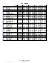
SECTIONAL VIEW OF <strong>PGV</strong>55, 75 & 11019
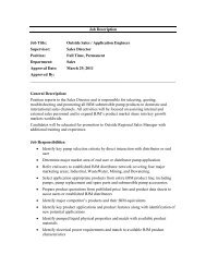
SECTIONAL VIEW OF <strong>PGV</strong>22020
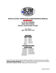
<strong>PGV</strong> SERIES PARTS LISTPump Model <strong>PGV</strong>55 <strong>PGV</strong>75 <strong>PGV</strong>110 QTY.Pos. No. Part Description Item # Item # Item # NEEDED01 Strainer 201821 201820 201820 102 Suction Cover 201824 201823 201823 103 Impeller Bolt 201826 201944 201944 104 Impeller Washer 201825 201825 201825 105 Impeller 201828 E00502 E00503 106 Impeller Key 201831 201827 201827 107 Pump Casing 201832 201830 201830 107-1 O-ring, BUNA-N 201834 201913 201919 108 Lower Oil Box 201923 201833 201833 108-1 O-ring, BUNA-N 201839 201912 201912 109 Lipseal, BUNA-N 201841 201838 201838 213 Mechanical Seal** 201680 201840 201840 114 Lower Ball Bearing 201844 201679 201679 114-2 Bearing cover 201849 E01412 E01412 116 Motor Housing 201922 201847 201848 116-1 O-ring, BUNA-N 201852 201911 201918 116S Pump Support 201856 201851 201851 117 Rotor w/ shaft 201860 201854 201855 118 Stator, 460V, 3PH 60Hz 201862 201858 201859 118-1 Lead Wire Support 201861 201861 201861 120 Upper Ball Bearing 201867 E02001 E02002 121A Upper Oil Box 201872 201865 201866 123 Motor Protector, 460V, 3PH 60Hz 201877 201870 201871 126 Bearing Housing 201922 201875 201876 126-1 O-ring, BUNA-N 201882 201915 201921 127 Power cord 201887 201880 201881 127-1 Bell Mouth 201891 201885 201886 127-2 Terminal Box 201924 201890 201890 127-2-1 O-ring, BUNA-N 201895 201914 201920 128 Cable Packing 201899 201893 201894 128-1 Cable Washer 201902 201897 2018981pc- model55,75 2pcsmodel11028-2 Screw Gland 201904 201900 201901 132 Cable Clamp 201908 201903 201903 134A Eyebolt (pump support) 201910 201907 201907 434B Eyebolt (Top of motor side oil box) 201916 201907 201908 138 Discharge Adapter 4" 201948 201910 201910 138-1 Gasket, discharge - F.R.R. 201947 201916 201916 150-01 Bolt (Strainer) 201950 201941 201941 450-02 Stud & nut (suction cover) 201930 201935 201935 650-07 Stud, nut & s-washer (pump casing) 201917 201933 201933 650-08 Stud, nut & s-washer ( lower oil box) 201940 201934 201934 450-11 Oil Plug 201940 201930 201930 250-11-1 Seal washer, BUNA-N 201946 201917 201917 250-14-2 Bolt & s-washer (bearing cover) 201946 201940 201940 450-18-1 Bolt (lead wire support) 201949 201942 201931 350-21A Stud, nut & s-washer (upper oil box) 201946 201933 201933 650-26 Stud, nut & s-washer (bearing housing) 201932 201933 201933 650-27 Bolt & s-washer (bell mouth) 201945 201937 201937 250-27-2Bolt & s-washer (terminal box)-model 55, 75Stud, nut & S-washer (terminal box)-model 201936 201936 201933 411050-32 Bolt & s-washer (cable clamp) 201938 201938 201938 250-38 Bolt & Nut (discharge flange) 201943 201943 201943 821
Pump Model <strong>PGV</strong>220 QTY.Pos. No. Part Description Item # Needed01 Strainer 201821 103 Impeller Nut 201824 104 Impeller Washer 201826 105 Impeller E00504 106 Impeller Key 201828 107 Pump Casing 201831 107A Guard Plate 201832 108 Lower Oil Box 201834 108-1 O-ring, BUNA-N 201923 109 Lip Seal, BUNA-N 201839 113 Mechanical Seal** 201841 114 Lower Ball Bearing 201680 114-2 Bearing cover 201844 116 Motor Housing 201849 116-1 O-ring, BUNA-N 201922 116S Pump Support 201852 117 Rotor w/ shaft 201856 118 Stator, 460V, 3PH, 60Hz 201860 118-1 Lead Wire Support 201862 120 Upper Ball Bearing E02003 121A Upper Oil Box 201867 123 Motor Protector 460V, 3PH, 60Hz 201872 126 Bearing Housing 201877 126-1 O-ring, BUNA-N 201922 127 Power cord 201882 127-1 Bell Mouth 201887 127-2 Terminal Box 201891 127-2-1 O-ring, BUNA-N 201924 128 Cable Packing 201895 128-1 Cable Washer 201899 128-2 Screw Gland 201902 132 Cable Clamp 201904 134A Eyebolt (pump support) 201908 438 Discharge Adapter 4" 201910 138-1 Gasket, discharge-F.R.R 201916 150-01 Bolt (Strainer) 201948 850-07 Stud, Nut & S-washer (pump casing) 201947 850-08 Bolt & S-washer (lower oil box) 201950 650-11 Oil Plug 201930 250-11-1 Seal washer, BUNA-N 201917 250-14-2 Bolt & S-washer (bearing cover) 201940 450-18-1 Bolt & S-washer (Lead wire support) 201940 350-21A Stud, Nut & S-washer (upper oil box) 201946 850-26 Stud, Nut & S-washer (bearing housing) 201946 850-27 Bolt & S-washer (Bell mouth) 201949 250-27-2 Stud, Nut & S-washer (terminal box) 201946 550-32 Bolt (cable clamp) 201932 250-38 Bolt & Nut (discharge flange) 201945 822
<strong>BJM</strong> PUMPS, LLC123 Spencer Plain RoadOld Saybrook, CT 06475, U.S.A.WARRANTY AND LIMITATION OF LIABILITYUnless otherwise expressly authorized in writing, specifying a longer or shorter period, <strong>BJM</strong><strong>Pumps</strong>, LLC warrants for a period of eighteen (18) months from the date of shipment from thePoint of Shipment, or one (1) year from the date of installation, whichever occurs first, that allproducts or parts thereof furnished by <strong>BJM</strong> <strong>Pumps</strong>, LLC under the brand name <strong>BJM</strong> <strong>Pumps</strong>,hereinafter referred to as the “Product” are free from defects in materials and workmanship andconform to the applicable specification.<strong>BJM</strong> <strong>Pumps</strong>, LLC’s liability for any breach of this warranty shall be limited solely to replacementor repair, at the sole option of <strong>BJM</strong> <strong>Pumps</strong>, LLC, of any part or parts of the Product found to bedefective during the warranty period, provided the Product is properly installed and is beingused as originally intended. Any breach of this warranty must be reported to <strong>BJM</strong> <strong>Pumps</strong>, LLCor <strong>BJM</strong> <strong>Pumps</strong>, LLC’s authorized service representative within the aforementioned warrantyperiod, and defective Product or parts thereof must be shipped to <strong>BJM</strong> <strong>Pumps</strong>, LLC or <strong>BJM</strong><strong>Pumps</strong>, LLC’s authorized representative, transportation charges prepaid. Any cost associatedwith removal or installation of a defective Product or part is excluded.IT IS EXPRESSLY AGREED THAT THIS SHALL BE THE SOLE AND EXCLUSIVE REMEDYOF <strong>BJM</strong> PUMPS, LLC’S DISTRIBUTORS AND CUSTOMERS. UNDER NO CIRCUMSTANCESSHALL <strong>BJM</strong> PUMPS, LLC BE LIABLE FOR ANY COSTS, LOSS, EXPENSE, DAMAGES,SPECIAL DAMAGES, INCIDENTAL DAMAGES OR CONSEQUENTIAL DAMAGES ARISINGDIRECTLY OR INDIRECTLY FROM THE DESIGN, MANUFACTURE, SALE, USE OR REPAIROF THE PRODUCT, WHETHER BASED ON WARRANTY, CONTRACT, NEGLIGENCE, ORSTRICT LIABILITY. IN NO EVENT WILL LIABILITY EXCEED THE PURCHASE PRICE OFTHE PRODUCT.THE WARRANTY AND LIMITS OF LIABILITY CONTAINED HEREIN ARE IN LIEU OF ALLOTHER WARRANTIES AND LIABILITIES, EXPRESSED OR IMPLIED. ALL IMPLIEDWARRANTIES OF MERCHANTABILITY AND FITNESS FOR A PARTICULAR PURPOSE AREHEREBY DISCLAIMED BY <strong>BJM</strong> PUMPS, LLC AND EXCLUDED FROM THIS WARRANTY.<strong>BJM</strong> <strong>Pumps</strong>, LLC neither assumes, nor authorizes any person to assume for it, any otherwarranty obligation in connection with the sale of the Product. This warranty shall not apply toany Product or parts of Product which have (a) been repaired or altered outside of <strong>BJM</strong> <strong>Pumps</strong>,LLC’s facilities unless such repair was authorized in advance by <strong>BJM</strong> <strong>Pumps</strong>, LLC or by itsauthorized representative; or (b) have been subject to misuse, negligence or accident; or (c)have been used in a manner contrary to <strong>BJM</strong> <strong>Pumps</strong>, LLC’s instruction.In any case of products not manufactured and sold under the <strong>BJM</strong> <strong>Pumps</strong>, LLC brand name,there is no warranty from <strong>BJM</strong> <strong>Pumps</strong>, LLC; however <strong>BJM</strong> <strong>Pumps</strong>, LLC will extend any warrantyreceived from <strong>BJM</strong> <strong>Pumps</strong>, LLC’s supplier of such products.23
START-UP REPORT FORMSTART-UP REPORT FORMThis form is designed to record the initial installation, and to serve as a guide for troubleshooting at alater date (if needed).<strong>BJM</strong> <strong>Pumps</strong>, LLC123 Spencer Plain RoadOld Saybrook, CT. 06475Pump Owner’s NameLocation of InstallationPerson in Charge Phone( )Purchased FromModelSerial NoVoltage Phase Hertz HPDoes impeller turn freelyby hand? Yes NoCondition of Equipment New Good Fair PoorCondition of Cable Jacket New Good Fair PoorRotation: Direction of Impeller Rotation (Use C/W for clockwise, CC/W for counterclockwise):Method used to check rotation (viewed from bottom)Resistance of cable and Pump Motor (measured at pump control)Red-BlackRed-WhiteWhite-BlackohmsohmsohmsResistance of ground circuit between control panel and outside of pumpsOhmsMEG OHM CHECK OF INSULATIONRed to ground White to ground Black to groundCondition of location at start-up Dry Wet MuddyWas equipment storedIf YES, length of storage:YesLiquid being pumpDebris in bottom of station? Yes NoWas debris removed in your Yes NoNo.
START-UP REPORT FORMpresence?Are guide rails exactly vertical? Yes NoIs base elbow installed level? Yes NoLiquid level controls: ModelIs control installed away fromturbulence?Yes<strong>Operation</strong> CheckTip lowest float (stop float), all pumps should remain off.Tip second float (and stop float), one pump comes on.Tip third float (and stop float), both pumps on (alarm on simplex).Tip fourth float (and stop float), high level alarm on (omit on simplex).If not on levels controls, describe type of controlsNoDoes liquid level ever drop belowvolute top?Control Panel MFG & model no.YesNumber of pumps operated by control panelNOTE: At no time should hole be made in top of control panel, unless proper sealingdevices are utilized.Short Circuit protection:Type:NoNumber and size of short circuit device(s) Amp rating:Overload type: Size: Amp rating:Do protective devices comply with Yes Nopump motor amp rating?Are all pump connections tight? Yes NoIs the interior of the panel dry? Yes NoIf No, correct moisture problem.Electrical readingsVoltage supply at panel lineconnection, pump offVoltage supply at panel lineconnection, pump onSINGLE PHASEL1 L2Amperage load connection, pump on L1 L2THREE PHASEVoltage supply at panel line connection, pump offL1L1-L2 L2-L3 L3-L1L2
START-UP REPORT FORMVoltage supply at panel line connection, pump onL1-L2 L2-L3 L3-L1Amperage load connection, pump onL1 L2 L3FINAL CHECKIs pump secured properly? Yes NoWas pump checked for leaks? Yes NoDo check valves operate properly?YesNoFlow: Does station appear to operate atproper rate?YesNoise level: Acceptable UnacceptableComments:NoDescribe and equipment difficulties during start-upInstalled by:Company:Person:Date:Maintained by:Company:Person:Date and time of start-upPresent at start-up:( ) Engineer’s name( )Contractor’s name( ) Operator’s name( ) others
NOTES:
123 Spencer Plain Road • PO Box 1138 • Old Saybrook, CT 06475, USA• Phone: (860) 399-5937 • Fax: (860) 399-7784Email: sales@bjmpumps.com • Web Site: www.bjmpumps.comCopyright © 2008-2013 <strong>BJM</strong> <strong>Pumps</strong>, LLC. All rights reserved.