Rialta Service Manual - RialtaInfo
Rialta Service Manual - RialtaInfo
Rialta Service Manual - RialtaInfo

You also want an ePaper? Increase the reach of your titles
YUMPU automatically turns print PDFs into web optimized ePapers that Google loves.
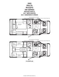
RIAL TA SERVICE MANUAL701674-19-000
~~~.~~~~~~~~~.~~~~~~~~~~~j~~~~~~~~~~~~~~~~~~~~~
~~~~~~~~~~~~~fA~~~~~~~~r-'~~~~~~~,...e-"~~~r~~~~TABLE OF CONTENTSSectionPageo. Information 0-11. Electrical 1-12. Exterior Body 2-13. Body Openings 3-14. Interior 4-15. LP Gas Fuel System 5-16. Appliances 6-17. Plumbing 7-18. Automotive 8-1Appendix A <strong>Service</strong> Tools 8-51Appendix B Sealants 8-56Appendix C Seals 8-57Appendix D Fan Motor Test Procedure 8-58Appendix E Capacitor Test Procedure 8-59Appendix F Use of Glass Insert Tool 8-61Appendix G Two Cloth Method 8-62Appendix H Dupont Paint Codes 8-63Appendix I Adhesive Application 8-64Appendix J Body Board Construction 8-65Appendix K Valance Panel Clips Installation 8-66Appendix L Compressor Motor Check Procedure 8-69Appendix M Front End Alignment Specifications 8-70~~fP'
~~r~r'"f!"'"f'"~~~~~~~~~~~~~~F'~SectionSECTION 0GENERAL INFORMATIONTABLE OF CONTENTSPageInformation 0-1<strong>Service</strong> Telephone Numbers 0-2Vehicle Identification Specifications 0-3Conversion Tables 0-4Jacking and Lifting 0-7Specifications and Capacities 0-9~~~~~~~~~~~~r-~~~~(ii'A~~~
~ !
~(':'~~~~~r-'f'"~~f'"('P'~~~~~~r~~~f'"f!A,-.~e-'~~e-'~(FA~('"~~,...~~,..~~SECTION 0GENERAL INFORMATIONThis manual contains information specific to the vehicle components installed by Winnebago Industries.For information ~egardinginformation.To obtain Volkswagen service information, contact:Dyment Distribution1-800-544-8021Hours: 9:00 a.m. to 5:00 p.m. ESTthe chassis of this vehicle, refer to the appropriate Volkswagen serviceAsk for a "Volkswagen Index". The index will be mailed to you. It includes a listing of service information,prices, and how to place an order.Or, you may also contact your local Volkswagen retailer.Keep this manual available for ready reference. It will aid the technician in providing quality service andrepairs to the vehicle.The methods described in this manual are based upon the most recent information available at the time ofpublication. Winnebago Industries, Inc., reserves the right to make any changes without prior notice.Winnebago Industries, Inc., reserves the right to make changes and to make additions to or improvement inits products without imposing any obligation upon itself to make such changes, improvements, or additionsto products previously manufactured.Winnebago may periodically publish service bulletins and manual revisions to either supplement orsupersede information in the manual. It is your responsibility to read these updates and file them in theappropriate section of this manual.CAUTIONTo properly reduce the chance of personal injury and/or property damage, the following instructions mustbe carefully observed.Proper service and repair are important to the safety of the service technician and the safe, reliableoperation of all motor vehicles. If part replacement is necessary, the part must be replaced with one of thesame part number or with an equivalent part. Do not use a replacement part of lesser quality.The service procedures recommended and described in this manual are effective methods of performingservice and repair. Some of these procedures require the use of tools specially designed for the purpose.Accordingly, anyone who intends to use a replacement part, service procedure or tool, which is notrecommended by the vehicle manufacturer, must first determine that neither his safety nor the safeoperation of the vehicle will be jeopardized by the replacement part, service procedure, or tool selected.It is important to note that this manual contains various "Cautions" and "Warnings" that must be carefullyobserved in order to reduce the risk of personal injury during service or repair, or the possibility that0-1
SECTION 0GENERAL INFORMATIONimproper service or repair may damage the vehicle or render it unsafe. It is also important to understandthat these "Cautions" and "Warnings" are not exhaustive, because it is impossible to warn of all thepossible hazardous consequences that might result from failure to follow these instructions.These vehicles contain some parts dimensioned in the metric system as well as in the domestic system. Somefasteners are metric and are very close in dimension to familiar customary fasteners in the inch system. It isimportant to note that, during any vehicle maintenance procedures, replacement fasteners must have thesame measurements and strength as those removed, whether metric or domestic. (Numbers on the heads ofmetric bolts and on surfaces of metric nuts indicate their strength. Domestic bolts used radial lines for thispurpose, while most domestic nuts to not have strength markings.) Mismatched or incorrect fasteners canresult in vehicle damage or malfunction, or possibly personal injury. Therefore, fasteners removed from thevehicle should be saved for reuse in the same location unless otherwise indicated. Where the fasteners arenot satisfactory for reuse, care should be taken to select a replacement that matches the original.Winnebago Industries, Inc.Forest City, Iowa 50436If after consulting this manual you require further technical assistance, please contact Winnebago Industries<strong>Service</strong> Department at:1·515·582·6939The following component manufacturers may also be contacted at their respective telephone numbers fortechnical assistance.Phillips IndustriesNentline Division(Monitor Panel)Magnetek(Converter)Norcold(Refrigerator)Suburban(Furnace)Coleman Company(dba/RV Products, Inc.)GeneracAtwood219-848-4491317-452-5444 .800-543-1219615-775-2131800-227-5693800-336-8389800-847-71600-2
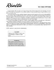
a~~~~~~r'"~~~~~e-'~~(PA(I"A~~(P"A~~(P,...~r~f!P'~~~~f!1""fP'~fP'fP",...~~~~,....VEHICLE IDENTIFICATION SPECIFICATIONSSECTION 0GENERAL INFORMATIONVehicle Certification Label - All <strong>Rialta</strong>s will display the vehicle certification label on the driver's door jamb.This label contains important information, including manufacturing date, G.V.W.R. limits, rim and tire sizeand inflation pressures, serial and model number, V.I.N. number, type of vehicle, and color specifications.Never destroy or remove this label. .. MANUFACTUREDBYINDUSTRIICSGAWR:FRT_~3 __ LB _....:3~_ KGRR 4 LB 4 KGMONTH AND YEAR OF MANUFACTURE: _~/ __SUITABLE TIRE AND RIM CHOICETIRERIM5 ____ ~6~ ____ ____5 ____....:6~______GVWR 2 LB. _2_ KGCOLD INFLATIONPRESSURE7 PSI 7 KPA 87 PSI 7 KPA 8PSIXXXTHIS VEHICLE CONFORMS TO ALL APPLICABLE FEDERAL MOTOR VEHICLE SAFETYSTANDARDS IN EFFECT ON THE DATE OF MANUFACTURE SHOWN ABOVE.KPA S~GSERIAL NO. 9 VIN ________..4.1~O____________TIPE 11 MODEL 12 COLOR ____ 1-.::;,3 __Explanation of Data:1. Month and year of manufacture at Winnebago Industries, Inc.2. Gross Vehicle Weight Rating: The total permissible weight of the vehicle, including driving, passengers,and the vehicle itself with all options, and hte load it is carrying, including all liquids. (Given all poundsand ki lograms.)3. Gross Axle Weight Rating - Front: The total permissible weight allowed for the front axle. (Listed inpounds and kilometers.)4. Gross Axle Weight Rating - Rear: The total permissible weight allowed for the rear axle. (Listed inpounds and kilometers.)5. Suitable Tire Choice: Tire recommended to meet handling and safety requirements. When replacing anytires on your vehicle, always replace with a tire that meets or exceeds these specifications.6. Suitable Rim Choice: Front/Rear: Wheel rim recommended to meet handling and safety requirements.When replacing any rim, always replace with a rim that meets these specifications.7. Cold Inflation Pressure: Front/Rear: Inflation pressure recommended (while cold) for the tires originallyequipped on your vehicle. These pressure levels must be maintained to assure proper handling, safety,and fuel economy.8. Rear Axle Wheel Configuration: Single, Dual, etc.9. Serial Number: This is the serial number assigned to your vehicle by Winnebago Industries.10. Vehicle Identification Number: This number is the legal identification number of your vehicle which willbe used on your vehicle's Title Certificate and Owner Registration Certificate. It is permanently attachedto the front left of the dashboard bracket and can be seen through the windshield from the outside ofthe vehicle.11. Type: This blank states the usage classification to which your vehicle belongs.12. Model: Lists the Winnebago product model number of your vehicle.13. Color: Signifies the base color code number of the vehicle.0-3
SECTION 0GENERAL INFORMATIONCONVERSION TABLEDECIMAL AND METRIC EQUIVALENTSDecimal Metric Decimal MetricFractions In. MM Fractions In. MM1/64 .015625 .39688 33/64 .515625 13.096871/32 .03125 .79375 17/32 .53125 13.493753/64 .046875 1.19062 35164 .546875 13.890621/16 .0625 1.58750 9/16 .5625 14.287505164 .078125 1.98437 37/64 .578125 14.684373/32 .09375 2.38125 19/32 .59375 15.081257/64 .109375 2.77812 39/64 .609375 15.478121/8 .125 3.1750 518 .625 15.875009/64 .140625 3.57187 41/64 .640625 16.271875/32 .15625 3.96875 21/32 .65625 16.6687511164 .171875 4.36562 43/64 .671875 17.065623/16 .1875 4.76250 11116 .6875 17.4625013/64 .203125 5.15937 45164 .703125 17.859377/32 .21875 5.55625 23/32 .71875 18.2562515164 .234375 5.95312 47/64 .734375 18.65312114 .250 6.3500 3/4 .750 19.0500017/64 .265625 6.74687 49/64 .765625 19.446879/32 .28125 7.14375 25132 .78125 19.8437519/64 .296875 7.54062 51164 .796875 '20.24.0625/16 .3125 7.93750 13/16 .8125 20.6375021/64 .328125 8.33437 53/64 .828125 21.03437. 11/32 .34375 8.73125 27/32 .84375 21.4312523/64 .359375 9.12812 55164 .859375 21.828123/8 .375 9.52500 7/8 .875 22.2250025164 .390625 9.92187 57/64 .890625 22.6218713/32 .40625 10.31875 29/32 .90625 23.0187527/64 .421875 10.71562 59/64 .921875 23.415627116 .4375 11.11250 15/16 .9375 23.8125029/64 .453125 11.50937 61/64 .953125 24.2093715132 .46875 11.90625 31132 .96875 24.6062531/64 .484375 12.30312 63/64 .984375 25.00312112 .500 12.70000 1 1.00 25.400000-4
,..,...(F'fAR«diaSECTION 0GENERAL INFORMATION~CONVERSION TABLE~Multiell BX To Get Eguivalent Number of:f!P'LENGlH,..~Inch 25.4 minimeters (mm)Foot 0.304 meters (m)Yard 0.914 meters~ Mile 1.609 kilometers (Ian)~AREA~ Inch2 645.2 millimeters 2 (mm2),...6.45 centimeters 2 (cm2)~ Foot 2 0.092 meters 2 (m2)yant 2 0.836 meters 2~~ VOLUME~ Inch' 16.387 mm'16.387 em'~0.016 litres (1)~ Quart 0.946 litres~ Gallon 3.785 litresYard' 0.764 meters' (m')~,..~ MASSPound 0.453 kilograms (kg)Ton 907.18 kilograms (kg)~Ton 0.907 tonne (t)~ Ounce 31.25 grams~FORCE~Kilogram 9.807 newtons (N)~ Ounce 0.278 newtonsr-' Pound 4.448 newtons~TEMPERATURE~Degreer-' Fahrenheit (OF-32) - 1.8 degree Celsius (C)~ACCELERATION~Footlsec2 0.304 meterlsec2 (mls2)~Inchlsec2 0.025 meterlsec2~~ TORgUE~Pound-inch 0.112 newton-meters (N-m)Pound-foot 1.355 newton-meters~ Pound-foot .1355 deca-newton meters (daNm)~~~~r-'0-5
SECTION 0GENERAL INFORMATIONCONVERSION TABLEMultil!ll Bl To Get Eguivalent Number of:POWERHorsepower 0.746 kilowatts (kW)PRESSURE OR VACUUMInches of water .354 barsPounds/sq. in. .068 barsENERGY OR WORKBTU LOSS joules (J)Foot-pound 1.355 joulesKilowatt-hour 3600000 joulesor 3.6 x 10 6LIGHTFoot candle 1.076 lumens/meter (ImIm)2FUEL PERFORMANCEMiles/gal. .0425 kilometerslliter (kmIl)Gal./mile 2.352 literlkilometer (l/km)VELOCIlYMileslhour 1.609 kilometerslhr (km/h)0-6
~~,.~~f!%F'JACKING AND LlFnNGJACKING AND LIFTING POINTSSECTION 0GENERAL INFORMATIONf!%F'fP"F'~~~~~,.,.."...(P'~~~~e-'~~""~~e-'e-'~~".~~,.~,.r-'r-'~,...~,...~When jacking or lifting the <strong>Rialta</strong>. Use the following lift points in accordance with the type of equipmentused.A = Front crossmember behind right front tire.B = Front crossmember behind left front tire.C = Rear jack plate ahead of right rear tire.o = Rear jack plate ahead of left rear tire.E = Rear axle.F = Rear axle0-7
~~~~~~~~~~SECTION 0GENERAL INFORMATIONTool<strong>Service</strong> Jack (Provided with vehicle) A, 8, C, 0Frame Contact Lift A, 8, C, 0(Twin Column Only!)Jacking and Lifting Points~~~~~~~~Axle Contact Lift (Two post movable piston)A, 8, E, F~~~CAUTIONDo NOT use the service jack to support the vehicle for any purpose other than changing a tire!~~~~~~~~~~~~~~~~~~~~~0-8~~
~~~~~~~e-'~~~~~~~F'~F'~~(IA~e-'~~F'r"~e-'~F'~~~~~~~~~~~~~VEHICLE SPECFICA TlONS AND CAPACITIESAutomotive Fluid Capacities• Fuel tank• Automotive Transmission (ATF)• Windshield Washer Container• Engine Oil- with fi Iter change- without filter changeCoach Fluid Capacities• Fresh water tank• Water heater• Gray water tank• Black water tank• LP Tank21.1 gals. (80 liters)3.2 qts. (3 liters)7.3 qts. (7 liters)5.8 qts. (5.5 liters)5.3 qts. (5.3 liters)16 gals. (60.56 liters)4 gals. (15.14 liters)6 gals. (22.71 liters)13 gals. (49.2 liters)28 Ibs. (12.68 liters)SECTION 0GENERAL INFORMATION0-9
~~~~~~~~~~~~~~~~SECTION 0GENERAL INFORMATIONSPECIFICA liONS• LengthWheel baseExterior height- with roof air- without roof ai r• Exterior Width• Interior Height (max.)• Interior Width• GVWR• GCWR20' 8"152"8' 4"7' 5"7' 4"6' 26' 10.5"7,000 Ibs.9,000 Ibs.~~~~~~~~~~~~~~~~~~~~~~~~~~0-10~~
""~~~~~(!FA~r'"~~~r'"~~e-'~~~~~~~~~r'"r'"r"~e-'r-'~r-'~~~~(P'TABLE OF CONTENTSSectionSECTION 1ELECTRICALPage110-Volt AC Installation Drawings 1-2Power Cord 1-5Load Center 1-8Circuit Breakers 1-13110-Volt AC Receptacles 1-14Ground Fault Interrupter 1-17Generator 1-1912-Volt DC Installation Drawings 1-22Auxiliary Battery 1-27Converter 1-29Auxiliary Start System 1-32Monitor Panel 1-37Rear Windshield Wiper 1-40Rear Defogger 1-49Entrance Door Power Lock 1-55Front Clearance Lights Removal and Replacement 1-57Rear Clearance Lights Removal and Replacement 1-58Tail Lights Removal and Replacement 1-59110-Volt AC and 12-Volt DC Wiring Diagrams 1-60Wire Code Chart 1-67~~~~~
~~~~~~~~~~~~~~~~~~~.~~~~~~~~~~~~~~~~~~~~~~.c;~~
SECTION 1ELECTRICALELEORICALWinnebago installs two separate electrical systems in the <strong>Rialta</strong>. The 110-volt AC system and the 12-volt DCcoach system.The 110-volt system is comprised of the following components:• Exterior shoreline power cord• Load center• Circuit breakers• Receptacles• Ground fault interrupter• Generator1-1
~SECTION 1ELECTRICAL~~~~~~~~~~~~~~~~~~~~~~~~~~~~~~~~IIOV LEFT ( US)~
SECTION 1ELECTRICAL/,.I J OV RIGHT (US)NnEI.
J J J J J J J J J j ]J J j J J J j j J J j j J J J J J j J J j J Jj J j j j j j j j J- •-1=10m r- '" mmqq-:;:00-zr- ~-DBn~D~BBD1Il1lllBIHIlIIJ II) 1111110000LOAD CENTERCUS)
~~FF~~~~~~~~~~~~~~~~~~~~~~F'~~~e-'~~~~~~~~(fP'SHOREUNE POWER CORDSECTION 1ELECTRICALThe shoreline power cord is located in the storage compartment on the left side of the rear cap. It is a 3-wirecable rated at 30 amps, which conducts 110-volt AC from a stationary power source (or the generator) to theload center.CAUTIONNever use an extension cord or adapter that is not rated for 30 amp service!~~~F'1-5
~~~~~~~~~~SECTION 1ELECTRICALSymptomTROUBLESHOOTINGCourse of Action1. If a failure of the power cord is suspected. 1. Unplug shoreline from power source. Use aplug in continuity tester to verify that voltage ispresent at the power source. Are 110 voltsavailable? (Yes) Proceed to Step 2. (No) Contactproper personnel to repai r cause of voltageloss.2. Visually inspect power cord for damage. Isdamage evident? (Yes) Proceed to Step 6. (No)Proceed to Step 3.3. Remove cover from the load center (reference"Load Center" in this section.) Inspectconnections. Is there evidence of poorconnections or other damage? (Yes) Repair.(No) Proceed to Step 4.4. Note locations of connections. Remove wiresfrom the hot, neutral, and ground connections.Disconnect power cord wires from the loadcenter. Use an ohmmeter to test the hot,neutral, and ground wires individually for highresistance or an open wire? (Yes) Proceed toStep 6. (No) Repeat this test while wiggling thepower cord. Pay special attention to the pointwhere the male plug in head mates to the cablebody. Did this test show evidence of highresistance or open? (Yes) Proceed to Step 6.(No) Proceed to Step 5.5. You should only arrive at this point if thepower cord has passed previous tests. Themalfunction is downstream of the power cord.Begin diagnosis at the load center.6. Replace shoreline power cord. Refer to"Shoreline Power Cord Replacement."~~~~~~~~~~~~~~~~~~~~~~~~~~~~1-6~~
SECTION 1ELECTRICALF'POWER CORD REMOVAL~ 1. Disconnect power cord from shoreli ne or generator power.2. Remove power cord plate retaining screws (6) (located in left rear cap trunk). Pull plate free of rear cap.3. Disconnect power cord wires at load center. Note location of wire connections for ease of laterinstallation.4. Loosen power cord connector at load center. Pull coad free of load center. Remove connector fromcable.5. Remove any clamps retaining the power cord.6. Pull power cord free of the vehicle.POWER CORD REPLACEMENT1. Place connector for power plate into cord.2. Route cord through rear cap and back wall up to the load center.3. Place connector for load center into cord. Route cord into load center.4. Make wire connections at load center. Tighten cord connector at load center.5. Install any power cord retaining clamps.6. Install power plate into power plate connector, tighten connector.7. Install power plate to rear cap. Secure with (6) retaining screws.1-7
SECTION 1ELECTRICAL110-VoltCircuit Breakers12-VoltCircuit FusesLOAD CENTERThe load center functions as a distribution point at which the various 110-volt AC and 12-volt DC circuitsbranch off from their main power supplies.110-volt AC power is fed into the load center via t he power cord which is connected to either stationaryshoreline power or the generator receptacle.12-volt DC power is fed int o the load center from the au xiliary battery via Wire J, or when the 110-volts ACis available from the converter via Wire M. (NOTE: Wires J and M are not physically marked. Reference''Wiring Diagrams" in this section.)The load center also houses the circuits overcurrent protection; 110-volt circuit breakers and 12-volt fuses.1-8
SECTION 1ELECTRICALTROUBLESHOOTING THE CONTROL CENTER AND ITS CIRCUIT1.SYMPTOMOne or more 11 O-volt loads are inoperative. 110 1.volts available from shoreline hook-up orgenerator.COURSE OF ACTIONReference appropriate 110-volt wiring diagramto determine what other loads are on theaffected ci rcuit. Proceed to Step 2.2. Attempt to operate other loads on the circuit.Do other loads function? (Yes) Proceed to Step3. (No) Proceed to Step 5.3. Check for 110 volts at the load. Are 110 voltspresent? (Yes) Failure is in the load. Repair orreplace. (No) Proceed to Step 4.4. Disconnect motor home from shore power.Disconnect negative leads from batteries torender generator set inoperable. Use anohmmeter to test for resistance and continuityon individual wires between last operative loadin the circuit and the first inoperative load.Does this test indicate high resistance or anopen in any wire? (Yes) Replace or repair thewire. (No) Visually inspect the wire todetermine the cause of voltage loss. Repair orreplace as necessary.5. Locate circuit breaker for affected circuit incontrol center. Reset. If loads are notfunctional, test for 110 volts at breaker output.Are 110 volts present? (Yes) Proceed to Step 6.(No) Proceed to Step 7.6. Disconnect motor home from shore power.Disconnect negative leads from batteries torender generator set inoperative. Use anohmmeter to check for high resistance or"open" in individual wires in the circuitbetween circuit breaker and first inoperativeload. Does this test indicate high resistance oran open? (Yes) Replace or repair affectedwiring. (No) Using a self-powered test, checkfor continuity between the hot wire andground. The hot wire and the neutral wire andthe neutral wire-to-ground. Continuityindicates a wire-to-ground or wire to wireshort. Repair or replace wiring as necessary.7. Check for 110 volts at input to breaker. Are 110volts present? (Yes) Replace the breaker. (See110-Volt Breaker Removal/Installation thissection.) (No) Proceed to Step 8.1-9
SECTION 1ELECTRICAL~~~SYMPTOMCOURSE OF ACTION8. Locate main circuit breaker in control center.Reset. If loads are not functional, check for 110volts at main breaker output. Are 110 voltspresent? (Yes) Proceed to Step 9. (No) Proceedto Step 10.9. Disconnect motor home from shore power.Disconnect negative leads from batteries torender generator set inoperative. Note locationof breakers. Remove breakers from controlcenter. (See Breaker Removal/Replacement thissection.) Inspect breakers and bus bar fordamage. Repair or replace as necessary.10. Check for 110 volts at the control center mainbreaker input. Area 110 volts present? (Yes)Replace the breaker. (See 110-volt BreakerRemoval/Installation this section.) (No) Thefailure is between the shore power connectioninput and the control center (See ShorelinePower Cord Troubleshooting in this section).~~~~~~~~~~~~~~~~~~~~~~~~~~~~~~~~~~~~~~~1-10~9
SECTION 1ELECTRICALTROUBLESHOOTING1.SYMPTOM12-volt DC loads are inoperative from battery 1.power, but function properly when vehicle isconnected to 110-volt AC power.COURSE OF ACTIONCheck auxiliary battery terminals. Are theyclean and tight? (Yes) Proceed to Step 2. (No)Clean and tighten as necessary.2. Check auxiliary battery voltage. Is battery fullycharged? (Yes) Proceed to Step 3. (No)Recharge or replace as necessary.3. Disconnect vehicle from 110-volt AC power.Check for 12 volts DC on Wire J* at the circuitbreaker in the auxiliary battery box. Is voltagepresent? (Yes) Proceed to Step 4. (No) Proceedto Step 5.4. Check for 12-volts DC on Wire J* at the loadcenter. Is voltage present? (Yes) Checkconnections at load center for tightness andcorrosion. Tighten and clean as necessary. (No)Troubleshoot Wire J to determine the cause ofvoltage loss. Repair or replace as necessary.*10, 8, and 6 gauge wires are not imprinted. Codeslisted for heavy gauge wires are for wiring diagramreference only.5. Check for 12-volts DC on Wi re A * at the ci rcuitbreaker located in the auxiliary battery box. Isvoltage present? (Yes) Proceed to Step 6. (No)Troubleshoot the circuit back to auxiliarybattery to determine the cause of the voltageloss. Repair or replace as necessary.6. Reset the circuit breaker by removing Wire A*.Then reconnect Wire A.1-11
SECTION 1ELECTRICALLOAD CENTER REMOVALCAUTIONDisconnect motor home from shore power or generator. Disconnect negative lead from auxiliary battery.1. Access backside of load center by removing the lower seat cushion of the left dinette seat. Reference"Dinette Seat Removal" in Interior Section.2. Open load center cover. Remove (4) screws retaining load center.3. Note the locations of the following wires:A. Power cord inputB. 110-volt AC outputs to branch circuitsC. Wire J auxiliary battery inputD. Wire M converter inputE. 12-volt DC outputs to branch circuits4. Loosen and remove wires from appropriate connectors.s. Remove load center retaining strap by removing (4) retaining screws.6. Pull load center forward out of its enclosure.LOAD CENTER REPLACEMENTCAUTIONDisconnect motor home from shoreline or generator power. Disconnect negative lead from auxiliarybattery.1. Position load center into opening. Secu.re with (4) retaining screws.2. Position retaining strap over load and secure with (4) screws.3. Reconnect wires to proper locations as noted in Step 3 of "Load Center Removal."4. Reconnect auxiliary battery negative lead.5. Close load center cover.1·12
~f'"~F'~~(I"Ae-'~~~~~r'"f!A~~~~~~~~~~~~e-'~("'A,..~~~"" fP'"""~~""~f""~,..110-YOLT AC ORCUIT BREAKERSSECTION 1ELECTRICALThe 110-volt AC circuit breakers are housed in the load center. They provide overcurrent protection for thevarious 110-volt AC branch circuits.110-YOLT CIRCUIT BREAKER REMOYALCAUTIONDisconnect motor home from shore power. Disconnect negative cables from batteries to render generatorset inoperative.1. Access breakers by removing control center cover.2. Grasp the individual breaker to be removed at the upper portion of its housing. Pull the breakeroutward until it comes free of the bus bar. Then lift the breaker upward slighly to clear the retainingtab.3. Loosen terminal set screw at bottom side of breaker. Remove wire from terminal.110-YOLT CIRCUIT BREAKER INSTALLATIONCAUTIONDisconnect motor home from shore power. Disconnect negative leads from batteries to render generatorset inoperative.1. Insert appropriate wire into terminal at bottom side of breaker. Tighten terminal set screw.2. Position breaker onto retaining tab.3. Apply pressure to the upper face of the breaker, pushing it back until it seats on the bus bar tab.4. Replace control center cover.1-13
~~~~~~~SECTION 1ELECTRICAL~~i\vc:=ac:=•Dc:a~.,/"~~~~~~~~~RECEPTACLESThe 110-volt AC receptacles are self-contained units. They do NOT require the use of a standard electricaloutlet box. The outlet has two pieces, the box assembly and the snap-on cover. It is held in place by twopawl clamps.RECEPTACLE REMOVALCAUTIONVehicle must be DISCONNECTED from 110-volt shore power!~~~~~~~~~~1. Loosen screws (2) on box assembly.2. Pull outlet forward out of mounting hole.3. Pry snap-on cover locking tabs outward to remove snap-on cover.RECEPTACLE REPLACEMENTCAUTIONVehicle must be DISCONNECTED from 110-volt shore power!NOTE: If you are installing new non-metallic sheathed cable, the following conditions must be observed:A. Slit cable sheathing 1 1/2 inches from connection point.B. Leave at least 4 inches of spare cable.~~~~~~~~~~~~~1-14~~
SECTION 1ELECTRICALKNOCKOUT TABREMOVEDGROUNDCONDUCTORGUIDEPOSTIt--CONDUCTORGUIDEPOSTCABLE GUIDE POST1. Place 110-volt wires into position as indicated on the snap-on cover.BEVELEDPOLARIZINGCORNERS2. Place snap-on cover and box assembly into proper position; taki ng care to align the beveled corners ofthe box assembly and the snap-on cover.1-15
SECTION 1ELECTRICALNOTE; WHEN INSTALLINGSWITCH, THE TOGGLEFITS IN THIS U~t:NIINl:i3. Use an outlet press (Winnebago Part Number 801627-01-000) to press the snap-on cover and bodyassembly together.4. Place outlet in wall opening.5. Tighten mounting screws (2).1-16
,.~~~r~~~~~~~~~~~~~~~~~~~~~~~~~~~~~~~~~~~RECEPTACLE WITH GFI ASSEMBLYo 0SECTION 1ELECTRICALThe GFI device protects against hazardous electrical shock that may be caused if the human body becomes apath through which electricity travels to reach ground. This could happen when touching an appliance orcord that is "Iive" through faulty mechanism, damp or worn insulation, etc. You don't even have to be onthe ground itself to be shocked, you could be touching metal or other material that leads to ground.When protected by the GFI, a person may still feel a shock, but the GFI should cut it off quickly enough so aperson in normal health should not have serious electrical injury. (Infants and very small children may still beaffected.)The GFI will NOT protect against:WARNING• Line-to-Iine shocks (the kind you would receive when touching metal inserted into the straight slots ofan electrical outlet);• Current overloads or line-to-line short circuits. The fuse or circuit breaker at the distribution box orpanel must provide such protection.CAUTIONIf the GFI trips of its own accord, this indicates a possible ground fault condition, which is potentiallyhazardous. Investigate the ground fault condition at once by making a thorough check to determinewhere the ground fault exists in the equipment plugged into the GFI. Correct the defect at once. Carry outthe test procedure outlined below to ensure that the GFI is operating properly. If the GFI does not reset,this indicates a ground fault still exists and must be corrected.~~~~1-17
~~~-'='i~SECTION 1ELECTRICALGFI TEST PROCEDUREThe GFI oulet should be checked every month to make sure it is operating properly.1. With shoreline power connnected, push the TEST button. The RESET button should pop out from theinner surface. This should result in power being OFF at all outlets. Verify by plugging test lamp intoevery outlet.CAUTIONIf RESET button does not pop out or if test lamp remains lit when RESET button does pop out, DO NOT USEANY OUTLETS ON THE CIRCUIT. Troubleshoot the electrical system to determine cause of fault. Repair asnecessary.2. If the GFI tests okay, restore power by pushing the RESET button back in. THE RESET BUTTONS MUST BEPUSHED FIRMLY AND FULLY INTO PLACE UNTIL IT LOCKS AND REMAINS DEPRESSED AFTER PRESSUREHAS BEEN REMOVED. IF THE GFI FAILS TO RESET PROPERLY, DO NOT USE. Troubleshoot the electricalsystem to determine cause of fault. Repair as necessary. Test lamp should again light.3. IF GFI TRIPS BY ITSELF at any time, rest it and perform Test Procedures 1 and 2 above. IF RESET BUTTONDOES NOT POP OUT WHEN TEST BUTTON IS DEPRESSED, DO NOT USE.~~~~~~~~~~~~~~~~~~~~~~~~~~~~~~~~~~~~~1-189~
~~~r'"~~~~~r"~~r""~~~~~r'~~~~(P'~~~~~~~~~,...~~~~~~~~~GENERATORSECTION 1ELECTRICALThe auxiliary generator is powered by gasoline drawn via a pick-up tube in the sending unit from the vehiclegas tank.NOTE: The pick-up tube is positioned so that the generator will not draw out the gasoline in the bottom114 of the tank.110-volt power from the generator is supplied to the shoreline receptacle box. To supply the coach withpower from the generator, it is necessary to plug the shoreline cord into the shoreline receptacle box.1-19
~~~~~SECTION 1ELECTRICALSYMPTON1. If no generator output is suspected.GENERATOR TROUBLESHOOTINGCOURSE OF ACTION1. Check breaker(s) on generator. Reset. Isgenerator output available? (Yes) Proceed toStep 2. (No) Proceed to Step 3.2. A blown breaker may be evidence of trying touse more amperes than are available on thecircuit. Reduce total amperage draw. If thebreaker(s) conti nue to open, proceed to Step 3.3. Generator set Troubleshooting and repairshould be performed only by trainedtechnicians. Trained technicians should refer tothe appropriate manufacturer's specificationsand shop manuals.~~~~~~~~~~~~~~~~~CAUTIONGenerator set troubleshooting, repair, andadjustment should NOT be performed byunauthorized personnel.~~~~~~~~~~~~~~~~~~~~1-20~~
SECTION 1ELECTRICALGENERATOR REMOVAL1. Place ignition key in OFF position.2. Disconnect negative lead from chassis battery.3. Disconnect tailpipe. from generator muffler.4. Disconnect battery cable from generator.5. Disconnect 12-volt control wiring connector at generator.6. Disconnect fuel line from filter at generator.7. Remove the junction box cover from junction box containing generator output wiring (located underthe left dinette seat). Note the location of connections for ease of later installation. Remove wire nutsfrom ground wire, neutral wire, and hot wire. Loosen the cable retaining clamp located at the junctionbox. Remove generator output wiring from junction box by gently pulling on sheathed cable.8. Support the generator set using a drivetrain removal lift.CAUTIONGenerator set must be supported prior to removal of generator retaining bolts due to the weight of thegenerator set.9. Remove generator (4) retaining bolts. Lower generator set. Remove from vehicle.GENERATOR REPLACEMENT1. Lift generator set into position using a drivetrain remove lift or equivalent.2. Insert (4) generator retaining bolts. Tighten.3. Route sheathed cable to junction box. Insert generator output wiring through the cable connector intojunction box. Connect wiring as noted during removal. Apply wire nuts. Tighten the cable retainingclamp.NOTE: The sheathed protective cable should be firmly seated in the connector. Do NOT apply clamppressure directly to unprotected wires. Install the junction box cover.4. Attach and secure fuel line to fuel filter on generator.5. Connect 12-volt control wiring to connector at generator.6. Connect and secure battery cable to generator.7. Connect and secure tailpipe to generator muffler.8. Connect negative lead to chassis battery.1-21
-INm '" r- mmqq-;QO-z~r-w..-LUl,FIIOftol2V LEFT IUS/CAN)JJJJJJJJjJ"JJJJJJJJjJJJJJjJjJJjjjJJJJjJJJjJjj
waanAA. E-E... __ ~~_ TO WSPDt tImIl12V RIGHT (US/CAN)94 H-SERIES...•NCAlWlRIIiS lliS1L-BOOY
SECTION 1ELECTRICAL~,~LITMT amr:Hfd'~AlSf.oICAlDI IIf110ftI'tJW:'a tmDI1-24MGGW~~~~~~~~~~~~~~~~~~~~~~~~~~~~~~~~~~~~~~~~~~
HHGo¥till 8-BFFEDA.-~u KT~ KSALwANWH TB --(. C.... ...Eoc... -~ ___ 111.''''"111c88"In F-Fto "Mill!AA'Cf:'4 ClInD.8 12-INVI
J J J J J J J J J J J J J J J J J J J J J J J J J j J J J j J J J J j J J J J J j j j J-ING'\m V\r- mmqq-:;QO-z,... ~-CIIIIIKT'--rEXTERIOR LIGHTING
""~~~~f!'"~~~~~~~~r-'~~(I'"~r""~~~~~r-'~~~r-'~~~~f'"~~~~~~~~AUXILIARY BATTERYGEN. MOTORHOMEBattery - 12V, Storage, GRP 31130 Amp Hour225 Minutes Reserve CapacitySECTION 1ELECTRICALThe auxiliary (house) battery is a 12-volt deep-cycle battery. It is located in the auxiliary batterycompartment which is in the floor of the vehicle behind the cab area.Access to the battery is gained by removing the auxiliary battery compartment cover.The auxiliary battery is charged by the following two methods:1. When the vehicle is connected to shoreline or generator 110-volt AC power, the converter provides a"trickle" charge to the auxiliary battery.2. When the vehicle engine is running, the alternator provides a charge to the auxiliary battery. This isaccomplished with the auxiliary start system. Reference "Auxiliary Start System" in this section.1-27
SECTION 1ELECTRICALAUXILIARY BATTERY REMOVAL1. Ignition key in the OFF position.2. Unlatch and remove the auxiliary battery compartment cover.3. Loosen and remove the battery cables.CAUTIONRemove the negative battery cable FIRST to reduce chances of arcing.4. Loosen and remove (2) battery tie-down nuts.5. Remove battery tie-down bracket.6. Remove battery.AUXILIARY BATTERY REPLACEMENT1. Place battery into auxiliary battery compartment.2. Position battery tie-down bracket over battery. Secure with (2) battery tie-down nuts.3. Connect and tighten battery cables.~~~~~~~~~~~~~~~~.c=;~~~~~~~CAUTIONConnect the negative cable LAST to reduce chances of arcing.~~~~~~4. Replace auxiliary battery compartment cover and latch.~~~~~~~~~~~91-28~~
'~~~~~~~~~~~~~~~~e-'~~~~~~~~~rr"~~r'"~~~~~~~~~~~CONVERTER~I IISECTION 1ELECTRICALThe converter is located in the left rear of the vehicle, beneath the left dinette seat. It accepts 110-volt ACand outputs 12-volts DC which is used to charge the auxiliary (house) battery and to operate the 12-volt DCloads. The convertor is rated for 40 amp output.1-29
SECTION 1ELECTRICALSYMPTOMTROUBLESHOOTING THE CONVERTER1. Auxiliary battery is not being charged when 1.vehicle is connected to 110-volt AC power.COURSE OF ACTIONTurn ignition key to OFF position. Disconnectvehicle from shoreline or generator 110-volt ACpower.Fully charge auxiliary battery, clean and tightenbattery connections. Proceed to Step 2.2. Access converter, remove converter cover plateby removing (1) retaining screw.Check for 12-volts DC between the positive andnegative lugs on converter. Is voltage present?(Yes) Proceed to Step 7. (No) Proceed to Step 3.3. Check for 12-volts DC on Wire J at load center.Is voltage present? (Yes) Troubleshoot Wire Mback to converter to determine cause of voltageloss. Repair or replace as necessary. (No)Proceed to Step 4.4. Check for 12-volts DC on Wire J at the circuitbreaker located in the auxiliary batterycompartment. Is voltage present? (Yes)Troubleshoot Wire J back to the load center todetermine cause of voltage loss. Repair orreplace as necessary. (No) Proceed to Step S.S. Check for 12-volts DC on Wire A at circuitbreaker located in the auxiliary batterycompartment. Is voltage present? (Yes) Proceedto Step 6. (No) Troubleshoot circuit back tobattery to determine cause of voltage loss.Repair or replace as necessary.6. Reset the circuit breaker by removing Wire A,then reconnect Wi re A.7. Connect vehicle to 110-volt AC power. Checkvoltage at positive and negative lugs of theconverter. Voltage should rise to 13-volts DC orhigher. If it does not, proceed to Step 8.NOTE: In time, the system voltage should rise to14-volts DC with no loads on. Depending onbattery condition, it could take 24 hours tocompletely recharge the battery.8. Check both converter ground circuits. Ifgrounds are good, converter is defective.~~~~~~~~~~~~~~~~~~~~~~~~~~~~~~~~~~~~~~~~~~1-30~~
SECTION 1ELECTRICALCONVERTER REMOVAL~ 1. Turn ignition key to the OFF position.~ 2. Disconnect vehicle from 110-volt AC power.3. Remove left dinette seat. Reference "Dinette Seat Removal" in Interior Section.4. Remove left dinette cover panel. Reference "Left Dinette Cover Panel Removal" in Interior Section.5. U npl ug converter.6. Open converter access panel by removing (1) retaining screw.7. Note location of black wire and green wire for ease of later installation. Disconnect wires, loosen wireconnector at converter, and pull wires free. Disconnect case ground wire.Do NOT let black wire short to ground.CAUTION8. Remove (4) converter retaining screws. Remove converter.CONVERTER REPLACEMENT1. Place converter into position. Secure with (4) retaining screws.2. Insert connector and wires into converter.3. Connect wires as noted in Step 7 of "Converter RemovaL" Secure connector.4. Replace converter access panel and secure with (1) retaining screw.5. PI ug i n converter.6. Replace left dinette cover panel. Reference "Left Dinette Panel Cover Replacement" in Interior Section.7. Replace left dinette seat. Reference "Dinette Seat Replacement" in Interior Section.1-31
SECTION 1ELECTRICALAUXILIARY START SYSTEMThe auxiliary start system has two functions:1. To allow energy from the auxiliary battery to be used to start the engine in the event of chassis batteryfailure.2. It allows the auxiliary battery to be charged by the engine alternator while the vehicle is running.Major components of the system are:Auxiliary Start SwitchAuxiliary Start SolenoidWhen the ignition key is placed in the RUN position, 12-volts DC is fed out on Wire WH to the switch. Itpasses through the switch on Wire LR to the solenoid. Energizing it, allowing continuity between the twosolenoid posts, and the auxiliary battery can be charged.When the chassis battery is depleted, the solenoid cannot energize because of a lack of current on Wire WHto the switch.Therefore, 12-volts DC is fed to the switch via Wire LS from the auxiliary battery. When the switch isengaged, current flows out on Wire LR to the solenoid. Energizing it, allowing continuity between the twosolenoid posts, and the energy from the auxiliary battery can now be uesd to start the vehicle.1-32
AUXILIARY START SYSTEMQiASSISIGNITIONCIRCUITeJcl IiU~~ST~ ~ST16 16PUR PUR12Bl.KI16EJGRN(LOCATED BaOWL£FT DASH)FUSES(LOCATh"D BELOW DASH)IGNITION RELAY(LOC"TED BELOWLEFT DASH)___ ~I!IiJ"I~T.;;..C_14 PUR--~~~~~14PUR------------------~~~~~~TB~ 14 PUR---r-~ BY 12 LT BLU---12BU
SECTION 1ELECTRICALSYMPTONTROUBLESHOOTING1. Auxiliary battery does not charge when vehicle 1.is running.NOTE: Test auxiliary battery to determine that it iscapable of holding a charge before beginningtroubleshooting.COURSE OF ACTIONAccess auxiliary battery. See "Battery Removal"in this section. Disconnect negative and positivebattery cables.CAUTIONDisconnect negative battery terminal FIRST toreduce the chances of arcing.CAUTIONIsolate positive battery cable from possiblegrounds to prevent arcing.2. Place ignition key in RU N position. Connect avoltmeter between auxiliary battery positiveand negative cables. Are 12-volts DC indicated?(Yes) Test auxiliary battery. Replace asnecessary. (No) Proceed to Step 3.3. Check for 12-volts DC at auxiliary battery postof solenoid with key in RUN position. Are 12volts present? (Yes) Trace cable back toauxiliary battery to determine cause of voltageloss. Repair or replace as necessary. (No)Proceed to Step 4.4. With ignition key in RUN position, check for12-volts DC at center terminal of solenoid. Isvoltage present? (Yes) Proceed to Step 13. (No)Proceed to Step S.5. With ignition key in RUN position, check for12-volts DC on Wire WH at fuse panel locatedbelow the dash. Is voltage present? (Yes)Proceed to Step 11. (No) Proceed to Step 6.6. With ignition key in the RUN position, check for12-volts DC on Wire KE feeding wire WH at thefuse panel. Is voltage present? (Yes) Replacefues. (No) Proceed to Step 7.7. With ignition key in the RUN position, checckfor 12-volts DC on Wi re KE at Pi n 87 of theignition relay. Is voltage present? (Yes) TroubleWire KE to determine cause of voltage loss.Repair or replace as necessary. (No) Proceed toStep 8.~~~~~~~~~~~~~~~~~~~~~~~~~~~~~~~~~~~~~~~~~~1-34~~
SECTION 1ELECTRICALSYMPTOMCOURSE OF ACTION8. Check for 12-volts DC on Wire SJ at Pin 30 ofthe ignition relay. Is voltage present? (Yes)Proceed to Step 9. (No) Troubleshoot Wire SJback to power source to determine cause ofvoltage loss. Repair or replace as necessary.9. With ignition key in the RUN position, check for12-volts DC on Wire ST at Pin 85 of the ignitionrelay. Is voltage present? (Yes) Proceed to Step10. (No) Troubleshoot Wire ST to determinecause of voltage loss. Repair or replace asnecessary.10. With ignition key in the RUN position, jumper awire from Pin 86 of the ignition relay to aknown good ground. Check for 12-volts DC onWire KE at Pin 87 of ignition relay. Is voltagepresent? (Yes) Troubleshoot wire MG to groundto determine cause for loss of voltage. Repair orreplace as necessary. (No) Replace the relay.11. With ignition key in the RUN position, check for12-volts DC on Wi re WH at the switch. Isvoltage present? (Yes) Proceed to Step 12. (No)Troubleshoot Wire WH to determine cause ofvoltage loss. Repair or replace as necessary.12. With ignition key in the RUN position, check for12-volts DC on Wi re LR at the switch. Is voltagepresent? (Yes) Trou bl eshoot Wi re LR todetermine cause of voltage loss. Repair orreplace as necessary. (No) Replace switch.13. Disconnect the negative battery cable from theauxiliary battery. Disconnect the positive cablefrom the auxiliary battery at the solenoid.With the ignition key in the RUN position,check for 12-volts DC on the auxiliary batteryside of the solenoid. Is voltage present? (Yes)Troubleshoot circuit back to auxiliary battery.(No) Proceed to Step 14.14. With the positive cable from the auxiliarybattery still disconnected at the solenoid andwith the key in the RUN position, jumper a wirefrom the case of the solenoid to the knowngood ground.Check for 12-volts DC on the auxiliary batteryside of the solenoid. Is voltage present? (Yes)Remove solenoid from vehicle, clean up groundcontacts, and reinstall solenoid. (No) Replacethe solenoid.1-35
SECTION 1ELECTRICALSYMPTOMCOURSE OF ACTION2. Auxiliary start function is inoperative. Cannot 1.use auxiliary battery to start engine.2.3.4.5.6.7.Check auxiliary battery. Is it fully charged? (Yes)Proceed to Step 2. (No) Recharge or replace asnecessary.Rocker the switch to the auxiliary STARTposition and hold. Check for 12-volts DC onWire LR at the solenoid. Is voltage present?(Yes) Proceed to Step 7. (No) Proceed to Step 3.Rocker the switch to the auxiliary STARTposition. Check for 12-volts DC on Wire LR atthe switch. Is voltage present? (Yes)Troubleshoot Wire IR to determine the cause ofthe voltage loss. Repair or replace as necessary.(No) Proceed to Step 4.Check for 12-volts DC on Wi re LS at the switch.Is voltage present? (Yes) Replace the switch.(No) Proceed to Step 5.Check for 12-volts DC on Wi re LS at the fusepanel (located in the load center). Is voltagepresent? (Yes) Troubleshoot Wire LS todetermine cause of voltage loss. Repair orreplace as necessary. (No) Proceed to Step 6.Check for 12-volts DC on Wire J at the fusepanel. Is voltage present? (Yes) Replace thes-amp fuse at Position 9 of the panel. (No)Troubleshoot Wire J back to the auxiliarybattery to determine cause of voltage loss.Repair or replace as necessary.Disconnect the negative cable from the chassisbattery. Disconnect the chassis battery positivecable from the solenoid.Rocker the switch to the auxiliary STARTposition and hold. Check for 12 volts DC on thechassis battery post of the solenoid. Is voltagepresent? (Yes) Troubleshoot circuit to starter.(No) Proceed to Step 8.8. With the chassis battery positive cable stilldisconnected from the solenoid, jumper a wirefrom the case of the solenoid to a known goodground.Rocker the switch to the auxiliary STARTposition and hold. Check for 12-volts DC at thechassis battery post of the solenoid. Is voltagepresent? (Yes) Remove solenoid from vehicle,clean up ground contacts, and reinstallsolenoid. (No) Replace the solenoid.1-36
~r'"~~~~~~~~~~c-'~~~~~~~~~~~(!"'"~~~rc'~~~~~~~~~fP'er-'~f!P'~NOTES:MONITOR PANELFEMALE15 PIN MATE-N-LO C1 1 IJ 1& I ,.'IIIJ •• 'MALE~ -t[~ I lAY an AIL.JL...l-.J...L-.J...L["t~,{£ UJr ,AD ..,_., 1UCIC_llAn. ~.P.'50'00'0PlW OHDDGEN. ONI.J:~D1-.ySTART OJ sn'lP )...-na 1I. UNLESS OTHERWISE SPECIFIED ALL WIRE IS 22 AWG. PANEL-MONITOR'\SECTION 1ELECTRICALThe monitor panel is located on the wardrobe cabinet wall. Its primary function is to allow monitoring ofthe following six functions:1. Holding tanks content level.2. Fresh water tank contents level.3. Liquid propane gas tank contents level.4. Auxiliary battery condition.S. Water pump condition.6. Generator condition.When the level test switch is engaged, the appropriate level is indicated by the indicator lights. This isachieved by the following:1-37
~SECTION 1ELECTRICALFor Fresh Water and Holding Tanks;The circuit board in the monitor panel sends a voltage signal down the appropriate sensor wire (one pertank). The voltage seeks ground through the probes mounted in the tank. (See schematic).If the tank is below 1/3 capacity, fluid in the tank allows an electrical connection between the lower set ofprobes. Now the voltage sent down the sensor wire can seek ground, but first must pass through tworesistors.The circuit board "senses" the resistance on the sensor wire and lights the appropriate indicator lights.At 213 full, the voltage must pass through only one resistor and at full, the voltage passes directly to ground.For LP Gas:The circuit board in the monitor panel sends a voltage down the sensor wire to the sending unit located onthe LP tank. As the fluid level in the tank charges, so does the resistance in the sending unit. Again, thecircuit board "senses" the resistance in the circuit and lights the appropriate indicator lights.For Battery ConditionThe circuit board simply monitors auxiliary battery voltage and then lights the appropriate indicator light.For the Water Pump:The water pump indicator light is lit when the water pump is on.For the GeneratorThe generator ON indicator lamp is lit when the generator is running.The monitor panel also contains a water pump switch and a generator START/STOP switch.~~r-;~~~~~~~~~~~~~~~~~~~~~~~~~~~~~~~~~~~~~~1-38~~
SECTION 1ELECTRICALMONITOR PANEL REMOVAL1. Remove (4) monitor panel retaining screws and pull panel outward to access back of panel.2. Disconnect 1S-pin connector from back of panel.3. Remove monitor panel.MONITOR PANEL REPLACEMENT1. Position monitor panel in front of opening.2. Connect 1S-pin connector to panel.3. Place monitor panel into opening. Secure with (4) retaining screws.1-39
SECTION 1ELECTRICALREAR WINDOW WIPERIWASHERThe rear wiper/washer system allows for two functions:1. Operation of the rear window wiper.2. Rear window washing with wiper action.MAJOR COMPONENTSRear Window WiperIWasher SwitchRear Window Wiper MotorRear Window Washer PumpOPERATIONThe wiper feature functions are as follows:• Key ON power is supplied to the switch at Terminal 2 via Wire TC.• When the switch is depressed in the WIPER position, 12-volts DC is supplied to the wiper motor via WireMR. The wiper motor will run until the switch is deactivated or the ignition key is turned OFF.• When the wiper motor is energized, 12 volts DC is supplied to the indicator lamp via an internalconnection. Ground for the indicator light is supplied via wire MG.NOTE: When the switch is deactivated and the motor is not yet in the PARK position, the motor receives itpower from Wire TC allowing it to return to PARK.The washer feature functions are as follows:• Key ON power is supplied to the switch at Pin 5 via Wire TC.• When the switch is depressed in the WASH position, 12-volts DC is supplied to the washer pump via WireSX.NOTE: The WASH position on the switch is spring loaded and, therefore, a momentary position.~~~~~~~~~~~~~~~~~~~~~~~~~~~~~~~~~• The WASH position also triggers the rear wiper in the same manner as described in Wiper Operation.• When the headlight switch is in the "on" position, 12 volts DC is supplied to the switch illumination bulbvia wire ML. Ground for the indicator light is supplied via wire MG.~~~~~~~~~1-40~~
ITO GROUND 16GRNL,._CONNECTS TOREAR WIPERSWITCH14PURI • .ooJTO a-tASSIS DASHILLUMINATIONCIRCUIT14 PURREAR WIPER/WASHER SYSTEMCONNECTS TOWASHER PUMP(LOCATED INBACKWALL)14 PUR---r--------------------------,.------- 14 GRNSX____..;..P~A~WIPER MOTOR~ MOUNTING BOLT14 GRN ---,...._.....-.--1, PA .... I_GR_O_UNO_~(LOCATED NEARLOAD CENTER ONLEFT CHASSIS RAIL)CONNECTS TOWIPER MOTOR(LOCATED INBACKWALL)14P14 PUR ----1HLCI...JIKEFUSES(LOCATED BELOW DASH)TC~ 1'2 ~_R:~:E::::::W~T--::= :: :: =======BL~ SJ BY 12 LT BLU----12BlK 12PUR~12BLK ---.--+-----12BLK--------------------------,CHASSIS BATTERY CIRCUIT(LOCATED BElOW DASH)TO CHASSISIGNITIONCIRCUIT16PUR12PUR12BLKSTMG....I~....IGNITIOH RELAY(LOCA TED BElOWLEFT DASH)TO GROUND
~~~SECTION 1ELECTRICAL~~TROUBLESHOOTING~~SYMPTOMCOURSE OF ACTION~1. Rear wiperinoperative.and washerfunctions are 1.With ignition key in the RUN position, check for12-volts DC on Wire TC at the automotive fusepanel. Is voltage present? (Yes) Proceed to Step7. (No) Proceed to Step 2.2. With ignition key in RUN position, check for12-volts DC on Wi re KE that feeds Wi re TC atthe automotive fuse panel. Is voltage present?(Yes) Replace the fuse. (No) Proceed to Step 3.~~~~~~~3. With ignition key in the RUN position, check for12-volts DC on Wire KE at Pin 87 of the ignitionrelay. Is voltage present? (Yes) TroubleshootWire KE to determine cause of voltage loss.Repair or replace as necessary. (No) Proceed toStep 4.4. Check for 12-volts DC on Wi re SH at Pi n 30 ofignition relay. Is voltage present? (Yes) Proceedto Step 5. (No) Troubleshoot Wire SJ todetermine cause of voltage loss. Repair orreplace as necessary.~~~~~~~~~5. With ignition key in RUN position, check for12-volts DC on Wire ST of Pin 85 of the ignitionrelay. Is voltage present? (Yes) Proceed to Step6. (No) Troubleshoot Wire ST to determinecause of voltage loss. Repair or replace asnecessary.6. With ignition key in RUN position, jumper awire from PIN 86 of the ignition relay to aknown good ground.~~~~~~~Check for 12-volts DC on Wi re KE at Pi n 87 ofthe relay. Is voltage present? (Yes)Troubleshoot Wire MG to determine cause forloss of ground. (No) Replace relay.7. With ignition key in RUN position, check for12-volts DC on wi re TC at Pi ns 5 and 2 of theswitch. Is voltage present? (Yes) Proceed to Step8. (No) Troubleshoot Wire TC to determinecause of voltage loss. Repair or replace asnecessary.~~~~~~~~~~~1-42~~
~~~~~~~~~~~~~~~~~~~~~F'~(!""~~~~~~~~~~~~~~~(P"~~SYMPTOM8.9.10.COURSE OF ACTIONSECTION 1ELECTRICALWith ignition key in RUN position, hold switchin the WASH position. Check for 12-volts DC onWire SX at Pin 6 and Wire MR at Pin 3 of theswitch. Is voltage present? (Yes) Proceed to Step9. (No) Replace switch.With ignition in RUN position, hold switch inthe WASH position. Check for 12-volts DC onWire SX at the washer pump and Wire MR atthe wi per motor. Is voltage present? (Yes)Proceed to Step 10. (No) Troubleshoot Wires SXand MR to determine cause of voltage loss.Repair or replace as necessary.Check and clean ground connections. If systemdoes not operate after establishing goodgrounds, replace the washer pump and wipermotor.1-43
~~~~~~~~~~~~SECTION 1ELECTRICAL~~~r-;~SYMPTOMCOURSE OF ACTION~2. Wiper function inoperative. Washer functionsproperly.1.With ignition key in RUN position, check for12-volts DC on Wi re TC at Pi n 2 of the switch. Isvoltage present,? (Yes) Proceed to Step 2. (No)Troubleshoot Wire TC to determine cause ofvoltage loss. Repair or replace as necessary.~~~~2.With ignition key in the RUN position, placeswitch in the WIPER position. Check for 12-voltsDC on WI RE M R at Pi n 3 of switch. Is voltagepresent? (Yes) Proceed to Step 3. (No) Replaceswitch.~~~~3.With ignition key in the RUN position, placeswitch in the WIPER position. Check for 12-voltsDC or Wire MR at the wiper motor. Is voltagepresent? (Yes) Proceed to Step 4. (No)Troubleshoot Wire MR to determine cause ofvoltage loss. Repair or replace as necessary.~~~~~4.Check and clean ground connection. If thewiper function is still not operational afterestablishing a good ground, replace the wipermotor.~~~~~~~~~~91-44~~
'~~~~~~~~~~~~~~~fP'(""Af!!P"~e""~~r"~~~~r-'-SYMPTOM3. Washer function inoperative. Wiper functions 1.properly.COURSE OF ACTIONSECTION 1ELECTRICALFirst, make certain that the washer bottlecontains fluid.With the ignition key in RUN Position, check for12-volt DC on Wire TC at Pin 5 of the switch. Isvoltage present? (Yes) Proceed to Step 2. (No)Troubleshoot Wire TC to determine cause ofvoltage loss. Repair or replace as necessary.2. With ignition key in RUN position, hold switchin WASH position. Check for 12-volts DC onWi re SX at Pi n 6 of the switch. Is voltagepresent? (Yes) Proceed to Step 3. (No) Replaceswitch.3. With ignition key in RUN position, hold switchin WASH position. Check for 12-volts DC onWire SX at the washer pump. Is voltagepresent? (Yes) Proceed to Step 4. (No)Troubleshoot Wire SX to determine cause ofvoltage loss. Repair or replace as necessary.4. Check and clean ground connection for washerpump. If the washer function is still notoperational after establ ishi ng a good ground,replace the washer pump.~(P'"~~~~~~~~~F"~~~1-45
SECTION 1ELECTRICAL~~~~~SYMPTOMCOURSE OF ACTION~4. Wi per does not park.1.With ignition key in RUN position, check for12-volts DC on Wire TC at the wiper motor. Isvoltage present? (Yes) Proceed to Step 2. (No)Troubleshoot Wire TC to determine cause ofvoltage loss. Repair or replace as necessary.~~~~2.Inspect wiper motor. Is green jumper wireconnected between Pins G and 3 of terminalblock on motor housing? (Yes) Proceed to Step3. (No) Connect jumper wire between Pins Gand 3 of terminal block.~~~~5. Rear wiper switch dash light inoperative.3.1.Adjust wiper arm.Is the headlight switch turned on?(Yes) Proceed to Step 2.(No) Turn on headlight switch.~~~~2.Check for 12 volts DC on wire ML at terminal 8of switch. Is voltage present? (Yes) Proceed toStep 3. (No) Trace wi re M L back to powersource to determine cause of voltage loss.Repair or replace as necessary.~~~~6. Rear wiper switch indicator light inoperative.1.2.Does the rear wiper function properly? (Yes)Proceed to Step 2. (No) Troubleshoot rearwiper.Turn ignition key OFF. Check for continuity toground on wire MG at terminal 7 of the switch.Is there continuity to ground? (Yes) Replace theswitch. (No) Trace wire MG to groundingterminal to determine cause for loss of ground.Repair or replace as necessary.~~~~~~~~~~~~~~~~~~~~1-46~~
-•~VTPfR 'IISlL-RfAR
~~~SECTION 1ELECTRICALREAR WIPER MOTOR REMOVAL1. Remove wiper arm retaining nut. Remove wiper arm and related hardware.2. Remove wiper assembly retaining nut.3. Access the wiper motor by removing access panel located in the upper inner back wall panel.NOTE: Early production units did not have an access panel. It will be necessary to remove the upper innerback panel to access the wiper motor. Reference "Upper Inner Back Wall Removal" in Interior Section.4. Note location of 12-volt DC wiring connections for ease of later installation. Remove 12-volt DC wires.5. Remove (4) motor assembly retaining nuts with washers.6. Remove wiper motor through access hose.NOTE: If you are replacing the motor with a new assembly, it will be necessary to remove the adapterplate from the old motor and attach it to the new motor.~~~~~~~~~~~~~~~~~~REAR WIPER MOTOR REPLACEMENT~~NOTE: If you are installing a new wiper motor, it will be necessary to attach the adapter plate from the oldmotor onto the new motor.~~~1. Place wiper motor assembly in proper position and secure with (4) retaining nuts with washers.2. Reconnect 12-volt DC wiring as noted in Step 4 of "Rear Wiper Motor Removal."3. Replace access panel.4. Install wiper assembly retaining nut.5. Align and install wiper arm assembly. Secure with wiper arm retaining nut.~~~~~~~~~~~~~~1-48~~
SECTION 1ELECTRICALREAR WINDOW DEFOGGERThe rear window defogger dissipates moisture from the surface of the rear window by heating the glass.Major ComponentsRear Window Defogger SwitchRear Window Defogger ModuleRear Window Defogger RelayRear Wi ndow Defogger GridOperation• When the defogger switch is depressed, it momentarily grounds the defogger module via Wire GW.• This causes the module to turn ON and send voltage out on Wire GU which triggers the defogger relayand lights the indicator light in the defogger switch.• When the relay is triggered by GU, 12-volts DC on Wire BY is allowed to pass through the relay and out onWire GY to the defogger grid.NOTE: Once the module is turned ON, it will keep power on Wire GU for ten minutes (+ 1 minute) unlessthe switch is engaged, which will momentarily ground the module shutting it off.-• When the headlight switch is in the on position, 12-volts DC is supplied to the switch illumination bulb viawire ML. Ground for the indicator light is supplied via wire MG.1-49
J J J J J J J J J J J J J J J J J J J J J J J J J J J J J J J J J J J J J J J JJ J j »-IVIoREAR WINDOW DEFOGGERCONNECTS TOREAR WINDOWDEFOGGER SWITCHm r- '" mmqq-::;a 0-zr- ~-CHASSIS DASHILLl.t4INA TION CIRCUIT16 GRN16 GRNCHASSIS BATTERY CIRCUIT(LOCATED BELOW DASH)FUSES(LOCATED BELOW DASH)KETCf"'~~~::~~~~::~_:::::=======~~~------------~------------------------------~~;:±=~ SJ BY " LT BLU--------------..., ....---t--14PUR12 12Bl..l(PlR-= ,16 PUR~ 12 Bl..K--4t--t-- 12 BU
~~F~~~r'"~~~~~~~~~~~~~~~~~~~~~~~~~~~~~~~~~~~~1.SYMPTOMTROUBLESHOOTINGCOURSE OF ACTIONSECTION 1ELECTRICALRear window defogger is inoperative. 1. Is the ignition key in the RUN position? (Yes)Proceed to Step 2. (No) Place key in RUNposition.2. Does the indicator light in the switch come onwhen the switch is activated? (Yes) Proceed toStep 16. (No) Proceed to Step 3.3. Is the rear window wiper operational? (Yes)Proceed to Step 8. (No) Proceed to Step 4.4. Check for 12-volts DC at Pin 87 of the ignitionrelay. Is voltage present? (Yes) TroubleshootWire KE to determine the cause of voltage loss.Repair as necessary. (No) Proceed to Step 5.5. Check for 12-volts DC on Pin 30 of the ignitionrelay. Is voltage present? (Yes) Proceed to Step6. (No) Troubleshoot Wire SJ to determinecause of voltage loss. Repair or replace asnecessary.6. Check for 12-volts DC on Pi n 85 of the ignitionrelay. Is voltage present? (Yes) Proceed to Step7. (No) Troubleshoot Wire ST to determinecause of voltage loss. Repair or replace asnecessary.7. Jumper a wire from Terminal 86 of the ignitionrelay to a known good ground. Does the relayfunction? (Yes) Troubleshoot Wire MG todetermine the cause for loss of ground. Repairor replace as necessary. (No) Replace relay.8. Check fuse feeding Wire WHo Is fuse okay? (Yes)Proceed to Step 9. (No) Replace fuse.9. Disconnect Wire WH from module. Check for12-volts DC on wi reo Is voltage present? (Yes)Proceed to Step 10. (No) Troubleshoot Wire WHto determine cause of voltage loss. Repair orreplace as necessary.10. Reconnect Wire WHo Disconnect Wire GW frommodule. Attach test light lead to 12 volts andprobe connector of Wire GW. Rocker defoggerswitch. Does test light momentarily light? (Yes)Proceed to Step 13. (No) Proceed to Step 11.1-51
~~~~SECTION 1ELECTRICAL~~~SYMPTOMCOURSE OF ACTION11. Disconnect Wire GW from defogger switch.Ohm test Wire GH. Does test indicate an openor high resistance? (Yes) Repair or replace WireGW. (No) Reconnect Wire GW to switch andmodule. Proceed to Ste 12.12. Disconnect Wire MG from switch. Attach testlight lead to 12 volts and probe connector ofWire MG. Does the test light? (Yes) Replaceswitch. (No) Troubleshoot MG circuit todetermine cause for loss of ground. Repair orreplace as necessary.13. Reconnect Wire GW. Disconnect Wire MG fromthe module. Attach test light lead to 12 voltsand probe connector on Wire MG. Does the testlight light? (Yes) Reconnect Wire MG. Proceedto Step 14. (No) Troubleshoot Wire MG todetermine cause for loss of ground. Repair orreplace as neecessary.14. Reconnect Wire MG. Activate switch to turndefogger on. Check for 12-volts DC at Pi n 85 ofdefogger relay. Is voltage present? (Yes)Proceed to Step 16. (No) Proceed to Step 15.15. Disconnect Wire GU from the module. Ohm testWire GU. Does test indicate an open or highresistance? (Yes) Repair or replace Wire GU.(No) Replace the module.16. Check for 12-volts DC at Pi n 87 of the defoggerrelay. Is voltage present? (Yes) Proceed to Step19. (No) Proceed to Step 17.17. Check for 12-volts DC at Pin 30 of the ignitionmodule. Is voltage present? (Yes) Proceed toStep 18. (No) Troubleshoot Wire BY todetermine cause of voltage loss. Repair orreplace as necessary.18. Jumper a wire from PIN 86 of the ignition relayto a known good ground. Does the relayfunction? (Yes) Troubleshoot Wire MG todetermine the cause for loss of ground. Repairor replace as necessary. (No) Replace thedefogger relay.~~~~~~~~~~~~~~~~~~~~~~~~~~~~~~~~~~~1-52~~
~~~SECTION 1ELECTRICAL~~~~~SYMPTOM19.COURSE OF ACTIONCheck for voltage on Wire GY of the defogger.Is voltage present? (Yes) Proceed to Step 20.(No) Troubleshoot Wire GY to determine causeof voltage loss. Repair or replace as necessary.~~~~r'"~20.Disconnect Wire HY at the defogger. Connecttest light lead to 12-volt DC power. Probe WireHY with test light. Does the test light light?(Yes) Troubleshoot the defogger grid. Repair orreplace as necessary. (No) Troubleshoot WireHY to determine cause for loss of ground.Repair or replace as necessary.~~~~~r-'~e-'~~~~~~~~~F'~~~~F'~~~~~~(P"1-53
~SECTION 1ELECTRICAL~~SYMPTOMCOURSE OF ACTION2. Rear window defogger will not turn OFF. 1. Check for 12-volts DC at Pi n 85 of the defoggerrelay. Is voltage present? (Yes) Proceed to Step3. (No) Proceed to Step 2.3.Rear wi ndow defogger switch dash light 1.inoperative.2. Remove the defogger relay. Check for DCvoltage on Wi re GY. Is voltage present? (Yes)Troubleshoot Wire GY to determine cause ofvoltage. Repair as necessary. (No) Replace thedefective relay.3.Disconnect Wire GU at the module. Check WireGU for voltage. Is voltage present? (Yes)Troubleshoot Wire GU to determine cause ofvoltage. Repair as necessary. (No) replace themodule.Is the headlight switch turned on?(Yes) Proceed to Step 2.(No) Turn on headlight switch.~~~~~~~~~~~~~~~2.Check for 12 volts DC on wire ML at terminal 8of switch. Is voltage present? (Yes) Proceed toStep 3. (No) Trace wi re M L back to powersource to determine cause of voltage loss.Repair or replace as necessary.~~~~4.Rear window defogger switch indicator light 1.inoperative.3. Turn ignition key OFF. Turn headlight switchOFF. Check for continuity to ground on wireMG at terminal 7 of the switch. Is therecontinuity to ground? (Yes) Replace the switch.(No) Trace wire MG to grounding terminal todetermine cause for loss of ground. Repair orreplace as necessary.Does the rear window defogger functionproperly? (Yes) Proceed to Step 2. (No)Troubleshoot rear window defogger.2. With rear window defogger actuated, check for12 volts DC on wire GU at terminal 3 of theswitch. Is voltage present? (Yes) Proceed to step3. (No) Troubleshoot wire GU back to defoggermodule to determine cause of voltage loss.Repair or replace as necessary.2. Turn ignition key OFF. Check for continuity toground on wire MG at terminal 7 of the switch.Is there continuity to ground? (Yes) Replace theswitch. (No) Trace wire MG to groundingterminal to determine cause for loss of ground.Repair or replace as necessary.~r-;~~~~~~~~~~~~~~~~1-54~~
SECTION 1ELECTRICALEntrance Door Power Lock with Dash Mounted Switch (Early 1995 Production)Beginning with Winnebago serial number 802295229819 all <strong>Rialta</strong>'s will employ a Volkswagen compatibleentrance door lock. Refer to the appropriate Volkswagen information for troubleshooting procedures.The entrance door power door lock allows the entrance door to be locked or unlocked from the drivers area.Major ComponentsPower Door Lock SwitchLock MotorOperation• Chassis battery voltage is supplied to terminal 3 of the switch via wire PW·. NOTE: On early productionunits wire PW may be labeled as wire MK.• When the switch is rockered to the lock position, 12-volts DC is supplied to the lock motor via wire WL.Ground is supplied on wire WM to the switch which supplies a connection to wire MG to complete theground path.• When the switch is rockered to the unlock position, 12 volts DC is supplied to the lock motor via wire WM.Ground is supplied on wire WL to the switch which supplies a connection to wire MG to complete thepath to ground.Entrance DoorLock Switch12345GreenWhiteRedWhiteBlackWM14GmMG114 GmPW 14 PurMG214GmWL 14 PurBlackRedEntrance DoorLock MotorTo ChassisBattCircuit1-55
~SECTION 1ELECTRICALTROUBLESHOOTING ENTRANCE DOOR POWER LOCK, DASH MOUNTED SWITCH(Early 1995 Production)SYMPTOMCOURSE OF ACTION1. Entrance door power door lock inoperative. 1. Check for 12 volts DC or wire PW at terminal 3of the switch. Is voltage present? (Yes) Proceedto Step 2. (No) Troubleshoot wire PW to powersource to determine cause of voltage loss.Repair or replace as necessary.2. With the door lock switch in the neutralposition, check for continuity to ground onwires MGI at terminal 2 and MG2 at terminal 4of the switch. Is continuity to ground present,?(Yes) Proceed to Step 3. (No) Troubleshootwires MG1 ~nd MG2 to determine cause for lossof ground. Repair or replace as necessary.3. Rocker switch to lock position and hold. Checkfor 12 volts DC on wire WL at terminalS of theswitch. Is voltage present'? (Yes) Proceed to Step4. (No) Replace the switch.4. Rocker switch to the unlock position and hold.Check for 12 volts DC on wi re WM at term i nal 1of the switch. Is voltage present? (Yes) Proceedto Step 5. (No) Replace the switch.5. Access entrance door lock motor. Disconnectwire leads at motor. Rocker switch to lockposition and check for 12 volts DC on wire WLat motor connector. Is voltage present'? (Yes)Proceed to Step 6. (No) Troubleshoot wire WHback to switch to determine cause of voltageloss. Repair or replace as necessary.6. Rocker switch to unlock position. Check forcontinuity to ground on wire WL at motorconnector. Is continuity to ground present?(Yes) Proceed to Step 7. (No) Replace switch.7. Rocker switch to unlock position. Check for 12volts DC on wire WM at motor connector. Isvoltage present? (Yes) Proceed to Step 8. (No)Troubleshoot wire WM back to switch todetermine cause of voltage loss. Repair orreplace as necessary.8. Rocker switch to lock position. Check forcontinuity to ground on wire WM at motorconnector. Is continuity to ground present,?(Yes) Replace motor. (No) Replace switch.~~~~~~~~~~~~~~~~~~~~~~~~~~~~~~~~~~~~~~~~1-56~~
~~~SECTION 1ELECTRICAL~(P'(P'~~('P'!\~~~~~II~~~~~r:-'~~~~~~~(""A~~~~~~~~~FRONT CLEARANCE LIGHT REMOVAL1. Gently pry lens off of light.2. Remove (2) lightbase retaining screws.3. Use a putty knife to carefully break the seal between the light base and roof cup.4. Lift light base away from roof cap.5. Disconnect 12 volt DC wiring from light base.6. Remove light base.FRONT CLEARANCE LIGHT REPLACEMENT1. Connect 12 volt DC wiring to light base.2. Place light base in proper position. Secure with (2) retaining screws.3. Place lens on light base. Push down to secure.4. Cap seal the perimeter of the light with sealant. (Winnebago Part #107828-01-000)~~~~(I"",...~1-57
SECTION 1ELECTRICAL~~~~~~~~~~~~~~~~~~~REAR CLEARANCE LIGHT REMOVAL1. Remove (2) retaining screws.2. Pull light away from rear cap.3. Disconnect 12 volt DC wiring from light.REAR CLEARANCE LIGHT REPLACEMENT1. Connect 12 volt DC wiring to light.2. Place light in proper position.NOTE: The lens seal must be located between the light assembly and the lens.3. Secure light with 2 retaining screws.~~~~~~~~~~~~~~~~~~~~~~~~~
~~~~~~~r'"~~~~~~F'~r""F'c-'~~~~r"'~~~~F'~~~~~~~~~~~~~~~TAIL LIGHTTAIL LIGHT REMOVAL1. Remove (2) tail light retaining screws.2. Pull tail light free of rear cap.3. Disconnect 12 volt DC wiring at tail light.4. Remove tail light.TAIL LIGHT REPLACEMENT1. Place tail light near opening in rear cap.2. Connect 12 volt DC wiring at tail light.3. Place tail light in proper position and secure with (2) retaining screws.SECTION 1ELECTRICAL1-59
~~~~~~~~~~~~~~~~SECTION 1ELECTRICALWIRING DIAGRAMSWinnebago Industries employs a two-color wiring system. With this system, the majority of Winnebagoinstalled 12-volt wiring will be comprised of purple wires and green wires. As a general rule of thumb,purple wires indicate the positive side of a circuit and green wires are grounds.For ease of service, all 12-, 14- and 16-gauge wires are imprinted with wire identification numbers ofpredetermined intervals throughout the length of the wire. (See Figure Below). The two- or three-digitletter code is the individual wire identifier.Only 12-, 14- and 16-gauge wires are imprinted with code numbers. Heavy gauge wires (10, 8, and 6 gauge)are not imprinted. Codes listed for heavy gauge wires are for wiring diagram reference only.The following wire identification chart lists the individual wire code, where the wire originates, wire color,and where the wire terminates. When consulting this information, be aware that this is only a guide. Certainmanufacturing conditions may cause variations to exist on some models.~~~~~~~~~~~~~~~~Wire Loom Part No.'=: ::: '!9~=::a1~;:'::;'"' ;·".:P~~~~~~Wire Code~~~91-60~~
HHGFEDc·,.(.i)ctH«a TO1IllI£~a=zrp~,,CIIJNCTW TOlIRIIDW.. SllIZP linN~"MJ=TII'f1FW~~WJPIR~.. ~USTNt '"_tvIIM.U'\.ATI:.,,-r'''-••-8(UlCA11D enJar:wna: IIUICIIJ,,, ...."--'"CAl ."... '",,, ...••'4'"- ill;;;telC'·'"Q" ...telIIItn'IftI",,-PAIftIUIIItn' IGIII£AII AUf 0I£AlD&WI""NJGIt~~FAIlCIIIIIUO'4_1-.----14 Nt---=-..-----FEDccue •II i ..... :::::Z::::::r;:;;! ....--... u:=L..J:i5 ...."'- •~------------I.~~-------,.----~~--%en -•-Al» IIU IHJ J Fill 1[_nlll WnMQIIIII£JH a.u:TIIICIol. PIlIP.~ sa "IIIIIG OIAllAIoN·AU10 ~nil AoIIOln~ w_nlll.LU .. en' • '111 AallTlOW. JI,_tlDl.MlTl ...8,lIEDI STA!TER I76rUt".3t ..lUI ""WIRING DIAGRAM-LEFT FRONT •'WIRE AlIt ...",6 ~A
j j J J J J J J J J J J j j J J J J J J J J J J j j J J J J j j J J J j J j j j j j j j-• Q\NHGIUDfT _rrt"-'. CIAN------I. ClAN"""'---+-~f---I,. :'T"l~'" IIIJ-- lJ..I!!!-,. ""----1. ""'"CIAN__....._L...le~12V". PNC.5f1 ff r;-. ax- ~~ = =.,TlDu¥: r=a.:ma:z,&:' E..!! 8 B ill B88 ~ ....&kiN .ti=fl"rl.n,~----'m...
871 6 1I 3 I I IIII"HWIRING DIAGRAM-SIDEWALL'"JIIC_II6&7111GGl-aWIRING_ t:JOG7lDIAGRAM-POW~ LOCK ENTRANCEF-E~-----------WLI~----~--------~~-------------MMlgcl------WIRING ,11__ 11..0. DIAGRAM-ADAPTER,RADIO~~ ~ .. - ___ --:l:~II..~ ~~~,-~I·-II'·- .~-a"'=iFol caWIRING DIAGRAM-LP DETECTOR SWITCHI~~ 'ftr,Lr'-YJF""'"EDD-cWIRING DIAGRAM-SIDEWALLIIIlIIE _ '''7411'cB1-~ f tr~J3.w:.: GAl I.JGH'r •• PIlI M It~~·:.L. NIIW::II II •• _------------------------ ,._~BA8 I7IWIRING DIAGRAM-DOOR LOCK'.'III!MM"~16 JIWIRING DIAGRAM-FURNACE GAS VALVEItz"AE~ -roaJ~\""YI:5 I 2 I1- "IIIINt: IlUORAM-BODY
J J J J J J J J J J J J J J J J J J J J J J J J J J J j J J J J j J J J J J J j j j j j-•~HA I 7 I 6.. I 3 I 2 I Immq '"q-;vO-z~H r-r- mI-I-a__GI-Fl-E..D-C1-B1-•r-;-t !...~-.,-.-----.. ,, i[I] ";'I ~CDmIQ. CIDII'at I 01:!:I:l----' .~ .... ;::00 'i"-II:''"' !:{- i I~ I ,.·1- " lU;r;;;;"l .. --., .... - ,~ : ' I .-----., .... -.! LEn~o~:~---., .... -----!---. ! .. -------., •.•. ----- 1'0-2 '.·2 ";'"i i •I l __________ ., .... ___ .. ~-.I •••• ------------li,I10;1IPCIIIIJI'~OI ,=r@JImPDCX I+.'t'o ~ji! AEF1t=~'CA,... 0< ,; ~IilU ) IWV O~" c;:-:, II ~-.I"II.--------' I, I! 'iI~ :, cama. CDI1D IlU J I! •.• m -----1 1~2I ',OIIIt ,I I ~1D~"LIn ~ OIlE1'I"E =" ~ ~ . IIi·· , I ,I I Ja "1L _______ 1J I I I I~! L:-_+::::::::'~'::: ,.. a------------ _____ J'0;--III! L_., •.•.____ ~ .r.~ IIIeHPCIIIIJIi=0tRaPla-IIiIII....Fl-E~0....Cl-SI-AICITEI,8 IL,o-.·i Iil:KMTali---:rCIIQNILUII6 I(CAN IIOV WIRING)..II 2I(US "~OY WIRING)" II-IOIIESIA
-.------"-'r--HGGFEDDc8WIRE DIAGRAM-BAa
J J J J J J J J J J J J j J J J J J J J J j J J J J J J J J J j J j J j J j j J j j j j-IenenHG~-r~l-:tF l '-:fF' l-:tF l l-:tF' Ill'Iii -+-+--I!,,_---l1::::----..I1 ----~+t-----I.~~'.""----------~. ~ Iiu--------------~~ r-----------------I·--~--------------------------------------,.aw____f,.CAtr- m '" mmqq-::00-z~r-FlI. PUi~==:::l~~:::::::'·~ ~~~--~--,.~---------------------~l.f'UI-~f..+:::...;-FEWIRE ASH-Cl.EARAN!:E/T AILLAMPSI1I1II£_".711DcWIRING DIAGRAMLICENSE PLAlEL»FS C __ II37311BA___ ! ........ __ . _ ... ___ .1 _____ ._ ..... . 6~ ________._. _'-._____ ~ __ ~ ____.____._....;;2~___..:....____..:....______J
SECTION 1ELECTRICALWIREFROMWIRECOLORTOWIRECOLORAGalley Ceiling Lamp Switch14 PurGalley Ceiling LampBOver Current Protection(30A· Breaker Typical)12 RedPower Passenger Seat(Buddy Seat)CPower Passenger Seat12 GreenGround0EPhone Input JackPhone CordRear Phone JackFPhone Input JackPhone CordExterior Phone JackGCircuit Brkr. (30 Amp)10 BlueInstr. Panel (Heater)HPhone Input JackPhone95038-01-000Front Phone JackJK(40 Amp.) Batt.Circuit Brkr. or Conver.Circuit Brkr. (40 Amp) Batt.8 Blk.a Blk.Coach 12V Panel/ConverterBattery ChargeCoach 12V PanelLMConverterCircuit Breaker (40 Amp)8 Grn.a Pur. (Blk)GroundConverter Battery ChargerNRefrigerator10 Grn.Chassis Grd. (Bat.JComp.)PRSTUCircuit Breaker (20 Amp)Refrigerator ChassisGround Bar - LeftGround Bar - RightConverter Chassis10 Blk.a Grn.a Grn.a Grn.a Grn.Refrigerator (3-Way)GroundGroundGroundGroundWhiteWXY1-67
~SECTION 1ELECTRICAL~~WIREAAABACFROM<strong>Service</strong> Eng. Soon LampTank (Water) Level SensorsTank (Main Holding)AD Tank (Aux. Holding #1)WIRECOLORTO16 Grn. Vehicle <strong>Service</strong> EngineSoon Lamp Circuit16 Grn. Ground16 Grn. Ground16 Grn. GroundWIRECOLORPinklTan~~~~~~~~AE Tank (Aux. Holding #2)16 Grn. Ground~AF Water Pump Switch #1AG Water Pump Switch #112 Red Monitor PanelWater Pump Switch #212 Blu. Water Pump Switch #2~~~AHAJBreaker - Run, Start (10A Fuse)Chassis Ground14 Pur. Brake Light SwitchBrake Warning Light12 Grn. Body Ground~~~AKChassis Ground12 Grn. Body Ground~ALHeater Control - Low12 Pur. Blower Motor - LowBrown~AMANAPARASATHeater Control - Med.Heater Control - HighIgnition Switch - Acc.HornRadioRadio12 Wht. Blower Motor - Med.12 Gry. Blower Motor - High14 Pur. Circuit Breaker14 Grn. Ground16 Grn. Speaker - Right Front, Gnd.16 Grn. Speaker - Left Front, Gnd.OrangeGray~~~~~~~AUAWOver Current Protection(1 SA Fuse Typical)Front Cargo Light Switch16 Pur. Front Cargo Light Switch16 Pur. Rear Cargo Light Switch~~~AXFront Cargo Light Switch16 Pur. Rear Cargo Light Switch~AYRear Cargo Light Switch16 Pur. Cargo Lights~~~~~~~~~~~1-68~~
SECTION 1ELECTRICALWIREFROMWIRECOLORTOWIRECOLORBAWindshield Wipers14 Grn.GroundBBACC Power16 Pur.I/P GaugesBCIndicator Lights14 Grn.GroundBOOver Cu rrent Protection(10A Fuse Typical)14 Pur.Brake lamp SwitchBEBlower Motor12 Grn.GroundBFWSW Pump/Horn14 Grn.GroundBGFuel Sender14 Pur.Fuel GaugeGH Run Only Pwr. (Relay 150)14 Pur.Engine WiringBJOver Current Protection(10A Fuse)16 Pur.Engine WiringBKOver Current Protection(10A Fuse)16 Pur.Feed Horn RelayBlCigar Lighter16 Pur.GroundBMBattery Power16 Pur.Cigar LighterBNAAC Power16 Pur.SpotlightBPGround14 Grn.Heated, Motorized MirrorBRMotor Mi rror Switch14 Pur.Motorized Mirror (R)BSHeat Mirror Switch14 Pur.Heated MirrorBTMotor Mirror Switch14 Pur.Motorized Mirror (l)BURun Power14 Pur.Heat, Motor SwitchesBWIngition Switch12 Pur.ACC FeedBXIgnition Switch12 Pur.Run FeedBYFuse Link12 Pur.Battery Supply1-69
~-,SECTION 1ELECTRICAL~~~WIRECAFuse LinkFROMWIRECOLOR12 Pur. Battery SupplyTOWIRECOLOR~~~~CBIgnition Switch12 Pur. Start~CCAlternator16 Pur. Alternator Warning Lamp~CDOil Pressure Warning Lamp16 Pur. Sender (Warning)~CECFCGCHWater Temp. Warning LampSwitchCI utch or Neutral Gear SwitchStart Relay16 Pur. Sender (Warning)14 Pur. TV Jack (Rear)14 Pur. Start Isolation Relay14 Pur. Engine Wiring~~~~~CJWindshield Washer Pump14 Pur. WiperlWasher Switch~CKCLSpeaker TV PositiveSpeaker TV Negative16 Pur. TV16 Grn. TV~.cw;CMCNCPCRInverter - PositiveInverter - NegativeInverter - Ground LugCheck Engine Lamp10 Grn. 1S-Amp Circuit Breaker16 Grn. Ground12 Grn. Ground16 Grn. Ground/GM Wire Asm.~~~~.c=;CSThermostat, Remote16 Grn. Ground~CTDRL Output16 Pur. Low Beam Headlights~CUDRL Enable16 Pur. Run/Start Circuit~CWexCYDRL PowerDRL ModuleDRL High Beam Disable14 Pur. Solenoid- Chassis Battery Side16 Grn. Ground16 Pur. High Beam Headlights~~~~~~~~~~~~~~1-70~~
SECTION 1ELECTRICALWIREFROMWIRECOLORTOWIRECOLOROAPersonal Computer10ga Blk.Battery Power (Pos.)DBPersonal Computer10ga Grn.Battery (Ground)DCAlC-Roof, Rear (Exh.)16 Pur.ThermostatDOAlC-Roof, Rear (Cool)16 Pur.ThermostatDEAlC-Roof, Rear (High)16 Pur.ThermostatOFAlC-Roof, Rear (Low)16 Pur.ThermostatOGIgnition Switch12 Pur.ACORunOHGauge-Emergency Shutdown14 Pur.Fuel Solenoid (Diesel)OJExhaust Fan Switch (Low)14 Pur.Exhaust Fan(s)OKExhaust Fan Switch (High)14 Pur.Exhaust Fan(s)OLExhaust Fan14 Grn.GroundOMAuto Htr. Switch (Common)10 BlueAccessory/Accessory RelayONRelay12 Pur.Condensor FansOPTV/Radio Speaker FeedSelect Switch14 Pur.TV/Radio Speaker SwitchingRelay (Oil Input)DRSlideout Room Switch16 Pur.HWH Wiring (Extend)OSRear AlC Condensor12 Grn.GroundOTFuse or Ckt. Bkr.14 Pur.Rear Htr.OUSlideout Room Switch16 Pur.HWH Wiring (Retract)OWSlideout Room Switch16 Grn.HWH WiringOXHWH Wiring16 Grn.Slideout Room SwitchOYHWH Wiring16 Grn.Slideout Room Relay1-71
SECTION 1ELECTRICAL~~~WIREEAEBECEDHWH WiringFROMSlideout Room Relay16 Pur.16 Pur.WIRECOLORTOSlideout Room Relay(Accessory Power)Slideout Room SwitchWIRECOLOR~~~~~~~~EEEFEGEHAir Ride Suspension Left DownSwitch PositionAir Ride Suspension Left UpSwitch PositionAir Ride Suspension LoomGroundAir Ride Suspension Right DownSwitch Position16 Pur.16 Pur.16 Grn.16 Pur.Air Ride Suspension Left HeightControl BoxAir Ride Suspension Left HeightControl BoxAir Ride Suspension ControlLamp GroundsAir Ride Suspension RightHeight Control Box~~~~~~~EJAir Ride Suspension Right UpSwitch Position16 Pur.Air Ride Suspension RightHeight Control Box~~EKAir Ride Suspension Auto ModeSwitch Position16 Pur.Air Ride Suspension HeightControl Boxes~~ELEMENEPERIgnition SwitchAir Ride Suspension CompressorAir Ride Suspension <strong>Manual</strong>Mode Switch PositionCircuit Breaker (15 Amp)Circuit Breaker (6 Amp)16 Pur.16 Pur.16 Pur.14 Pur.14 Pur.Air Rid e SuspensionAuto/<strong>Manual</strong> Mode SwitchWarning Compressor On LampLevel Control Switches andIndicator LampSpot LampElectric Step - Kill Sw.~~~~~~~ESElectric Step - Kill Switch14 Pur.Electric Step - Wiring~ETCircuit Breaker (6 Amp)16 Pur.Refigerator (2-Way)~EURefrigerator (2-Way)16 Grn.Ground~EWEXEYFuel Heater SwitchSwitch TelevisionOvercurrent Protection(16 qa Fuselink Typical)14 Pur.14 Pur.12 Pur. Lt. BlueFuel Heater (ds)Wall Plate - TVIgnition Switch Feed #2~~~~~~~~~~1-729~
SECTION 1ELECTRICALWIREFROMWIRECOLORTOWIRECOLORFADriver's Door Passenger SidePower Window Switch (Down)(Pin 2) 14 Pur.Passenger's Power WindowSwitch (Pi n 2)FBDriver's Door Passenger SidePower Window Switch (Up)(Pin 4) 14 Pur.Passenger's Power WindowSwitch (Pi n 4)FC Passenger's Door Power (Pin 1)Window Switch14 Pur.Power Window Motor (Pass.Door) (Down)FD Passenger's Floor Power (Pin 5)Window Switch (Pin 5)14 Pur.Power Window Motor (Pass.Door) (Up)FEWater Pump Latching Relay CoilGround Contract16 Grn.GroundFFWater Pump Momentary Switch16 Grn.GroundFGWater Pump Latching RelaySwitch (Normally Open)12 Pur. (Gray)Water PumpFHOvercurrent Protection (10 ABraker Typical)12 Pur. Lt. BlueWater Pump or Latching RelayCommonFJSwitch - Pump, Bath12 Lt. BlueSwitch - Pump, Shower, Ext.FKSwitch - Pump, Bath12 GraySwitch - Pump, Shower, Ext.FLSwitch - Second Porch Lamp14 Pur.Second Porch LampFMSolenoid Mounting Bolt14 Grn.GroundFNElectric Door Indicator Switch16 Pur.Door Open Lamp Switch (Dash)FPFRCircuit Breaker/RelayFord Acc.lRun Circuit (Wht.lPur.10A)FS Docking Lights Relay (Pin 87)FTFUFWFXDocking LightsAutomotive Air WiringSwitch - Docking LightsOvercurrent Protection (30 ABreaker Typical)14 Pur.14 Pur.14 Pur.14 Pur.14 Pur.14 Pur.12 Pur. Lt. BlueAux. Fans/HeaterDocki ng Lights, Relay RearMonitorDocki ng LightsGroundAlC CI utch SwitchRelay - Docking Lights (Pin 85)Power Driver Seat (6-Way)FYPower Driver Seat (6-Way)12 Grn.Ground1-73
~SECTION 1ELECTRICAL~~WIREGAFROMWiper Control Module16 Pur.WIRECOLORTOWi per Switch (Power Feed)WIRECOLOR~~~~GBWiper Control Module16 Pur.Wiper Switch (Speed Control)~GCGOWiper Control ModuleWiper Control Module16 Pur.16 Pur.Wi per Switch (Washer BottlePump Feed)Wiper Motor (S Terminal)~~~GESwitched Dome Lamp Feed16 Pur.Dome Lamp~GFCommon Rear Channel SpeakerReturn16 Grn.Rear Speakers~~GGCruise Set16 Pur.Speed Control Amplifier~GHGlow Plug Wart Lamp (DieselEngine)14 Grn.Engi ne Sender~~GJGKCouch Battery PowerAi r Horn Switch16 Pur.14 Pur.LP Detector OvercurrentProtectionChassis Horn~~~GLGMGNGPWater/Holding Tanks LevelSensorsJet Air Ride Suspension PressureSensorsRear TV Speaker Output(PositiveRear TV Speaker Output(Negative)16 Grn.16 Pur.16 Pur.16 Grn.. GroundCheck Rear Ai r Suspension DashWarning LampRear TV Speaker (Positive)Rear TV Speaker (Negative)~~~~~~~GRThermostati cally ControlledRoof Vent (Send)14 Pur.Thermostat (Return)~~GSGTGUGWThermostatically ControlledRoof Vent (Return)Radio Power Switch(Memory Feed)Defog Module OutputDefog Switch On/Off14 Pur.16 Pur.16 Grn.16 Grn.Thermostat (Return)Radio (Memory Feed)Defog Relay, Indicator LampDefog Module On/Off~~~~~~GXXX XXX~GYDefog RelayI12 RedDefog Unit~~~~~~1-74~~
SECTION 1ELECTRICALWIREFROMWIRECOLORTOWIRECOLORHAReading Lamps Switch(93 Vans)14 Pur.Reading LampsHBMood Lamps Switch14 Pur.Mood LampsHC12 V Power Source14 Pur.Over Current Protection(1 SA Fuse Typical)HDSofa Slide Motor (Positive)14 Pur.Sofa Monoplex ControllerHESofa Slide Motor (Negative)14 Grn.Sofa Monoplex ControllerHFSofa Recl i ne Motor(Positive) 94 Vans14 Pur.Sofa Monoplex ControllerHGSofa Recl i ne Motor(Negaive)14 Grn.Sofa Monoplex ControllerHHSofa Monoplex Switch16 Pur.Sofa Monoplex ControllerHJSofa Monoplex Switch16 Grn.GroundHKSofa Monoplex Controller14 Blk.GroundHLFlood Lamp Switch14 Pur.Flood LampHMRear TV Speaker Output(Positive)16 Pur.Rear TV Speaker (Positive)HNRear TV Speaker Output(Negative)16 Grn.Rear RV Speaker (Negative)HPOver Current Protection16 Pur.Rear AlCHRSwitch (94 1200 ModemVan)14 Pur.12 Volt ReceptacleHSHTHUHWHXHY1-75
SECTION 1ELECTRICAL~~~WIREJAFROMControl Center/Fuse BlockWIRECOLORTO12 Pur. Monitor Panel/IsolatedWIRECOLOR~~~~JBControl Center/Fuse Block14 Pur. Main Furnace~JCControl Center/Fuse Block14 Pur. Light Circuit No. 1~JOControl Center/Fuse Block14 Pur. Light Circuit No.2~JEJFJGJHJJControl Center/Fuse BlockControl Center/Fuse BlockControl Center/Fuse BlockMain Furnace (+ 12 VDC)Main Furnace (Heat)14 Pur. Light Circuit No.314 Pur. Light Circuit No. 414 Pur. Light Circuit No. 516 Pur. Main Furnace Thermostat16 Pur. Mai n Fu rnace Thermostat~~~~~~JKAuxiliary Furnace16 Pur. Auxiliary Furnace Therm.~JLAuxiliary Furnace16 Pur. Auxiliary Furnace Therm.~JMINJPJRJSMain FurnaceLight Circuit No.5Light Circuit DevicesMonitor PanelMonitor Panel14 Grn. Chassis Ground14 Grn. Chassis Ground14 Grn. Chassis Ground16 Pur. lP Tank #212 Wht. Water PumpGreyWhite~~~~~~JTMonitor Panel16 Pur. LP Tank #1RedlWht.~JUMonitor Panel14 Pur. Water HeaterBlu.lWht.~JWJXJYMonitor PanelWater HeaterWater Pump14 Pur. Water Heater14 Grn. Chassis Ground12 Grn. Chassis GroundBrnGreen~~~~~~~~~~~~~~~~1-76~~
,.~r-'(!PA.f"""~~~f"'",...WIREKAKBKCKDFROMCircuit Breaker 25 AmpCircuit Breaker 25 AmpStep Ki II SwitchDoor Jamb Step SwitchWIRECOLOR10 Pur. Electric StepTO10 Wht. Step Ki II Switch10 Wht. Electric Step14 Grn. Electric StepSECTION 1ELECTRICALWIRECOLOR(Red)(White)(Brown)~~~~~~KEKFKGKHKJAuto Fuse BlockAux. Battery Discon. SWVent-lift, Power (Red)Vent-lift, Power (Blue)Vent-lift, Power (Blk)14 Pur. Elec. Step/RR Auto Htr SW16 Grn. Ground/lnstr. Panel14 Pur. Switch-(U p-Position)14 Pur. Switch-(Down-Position)14 Pur. Switch-Fan(Yellow)RedBlueBrown~KKRadio-Rear16 Pur. Speaker-Rignt~KLRadio-Rear16 Grn. Speaker-Right (Ground)~~~~~("'"KMKNKPKRKSVent-lightRadio-RearRadio-RearAntenna-Rear, RadioSwitch-Heater, High Speed14 Pur. Switch-light16 Pur. Speaker-Left16 Grn. Speaker-Left (Ground)14 Grn. Ground14 Pur. Rear Auto Heater (2)YellowChassisOrange~KTSwitch-Heater, Med. Speed14 Pur. Rear Auto Heater (3)Yellow~KUSwitch-Heater, Low Speed14 Pur. Rear Auto Heater (4)Red~~~~K.WKXKYRadioRadioRadio16 Pur. Speaker-Right Front16 Pur. Speaker-Right Rear16 Pur. Speaker-Left Front~~,...~~~~~~~~~~~1-77
SECTION 1ELECTRICALWIRELALBLCRadioRadioRadioFROMWIREWIRECOLOR TO COLOR16 Pur. Speaker-Left Rear16 Grn. Speaker-Right Rear, Ground16 Grn. Speaker-Left Rear, GroundLDLELFLGLHULKFuse Block-AutoSwitch-Fans, DefoggerSwitch-Fans, DefoggerRelay-Terminal IRelay-Terminal SRelay-Battery SideRelay-System Side16 Pur. Accessory Power14 Pur. Fans-Defogger, Hi Speed Black14 Pur. Fans-Defogger, Low Speed Red16 Pur. Switch-Disconnect, Bat.16 Pur. Switch-Disconnect, Bat.16 Pur. Switch-Disconnect, Bat.16 Pur. Indicator LightLL Generator (Start) Red (2)LM Generator (Stop) Orn (2)LN Generator (Ground) Grn (1)LP Generator (Run) Blue (6)16 Grn. Instru. Panel (See Dia)16 Grn. Instru. Panel (See Dia)16 Grn. Instru. Panel (See Dia)16 Pur. Instru. Panel (See Dia)LRLSLTLULWLXLVSwitch-Mode, BatteryCircuit Breaker 6 AmpSwitch-Cond., BatteryBrake Switch, Chev-WhtIWlreWi per Control Mod/ParkWiper Control Mod/Low SpdWiper Control Mod/High Spd14 Pur. Solenoid-Battery16 Pur. Switch-Mode/Condo Battery16 Pur. Voltmeter-12 Volt DC14 Pur. Brake LightS/4 Light Sys.14 Pur. Wi ndshield Wi pers-Front14 Pur. Windshield Wipers-Front14 Pur. Windshield Wipers-Front1-78
~~SECTION 1ELECTRICAL~~r"'~WIREMAFROMWi per Control Mod16 Pur.WIRECOLORTOBottle-Washer, WindshieldWIRECOLOR~MBFuse Panel-Auto, WSW14 Pur.Circuit Breaker 6 Amp~MCIP Lamp Circuit16 Grn.Chassis Ground~MDCircuit Breaker (15 Amp)14 Pur.Relay/Remote, Mirror~~~~~~MEMFMGMHMJCircuit Breaker (15 Amp)Circuit Breaker (15 Amp)Ground BoltFuse Panel-Choke Conn.Fuse Panel-Auto, WSW (*-05)14 Pur.14 Pur.14 Grn.16 Grn.14 Pur.Relay/Air HornsRelay/Fog LightsRemote Mirror, Fog, Air HornsChoke LightWi per Control ModBluelWhite~r-'MKMLFuse Panel-Auto, Bat (*-03)Fuse Panel-Auto, LPS (*-02A)14 Pur.16 Pur.Battery PowerInstr. Panel Lamps (Reostat)~~~r~~MMMNMPMRMSClearance LightsDome Light, Switched Grd.StepswitchRear Wiper, SwitchClearance Lights14 Pur.16 Grn.14 Grn.14 Pur.14 Grn.Clearance LightsDoor SwitchGroundRear Wiper (Low)Ground~MTStep-Electric8 Grn.GroundChassis~~~MUMWRadio Cigarette Lighter(Battery Circuit)Fuse Panel-Chec Eng Conn14 Grn.16 Pur.GroundCheck Engine LightBrnlWht~MXWi per Switch (High)16 Pur.Relay-Wiper~MYHeadlight (Power)14 Pur.Smart Stick ModuleYellow~~~~~~r~~~r"~~~. 1-79
~SECTION 1ELECTRICAL~~WIRENAFROMHeadlight (Low)WIRECOLORTO14 Pur. Smart Stick Module-RelayWIRECOLORGM-Tan~~~~NBHeadlight (High)NC Light (Circuit #1)NO Light (Circuit #2)14 Pur. Smart Stick Module-Relay14 Grn. Ground14 Grn. GroundGM-Lt.Grn.~~~~NE Light (Circuit #3)14 Grn. Ground~NF Light (Circuit #4)14 Grn. Ground~NGNHNJNKNLFoglight SwitchRelay-Fog LampsChassis Horn Feed CircuitAi r Horn SwitchRelay-Air Horn16 Pur. Relay-Fog Lamps14 Pur. Fog Lamps Relay16 Pur. Ai r Horn Switch16 Pur. Air Tank14 Pur. CompressorDk. Grn.~~~~~~NMControl Center/Fuse Block14 Pur. Front Lights-RH Light Circuit #6~NNRemote Mirror, Left16 Pur. Switch-N, Switch-Horiz-PYellow~NP~NRNSNTNURemote Mirror, LeftSwitch-Heati ng ElementRelay-Remote MirrorSwitch-Aisle Lights16 Pur. Switch-N, Switch-Vert-P14 Pur. Remote Mirror/Htg. Ele.14 Pur. Switches14 Pur. Switches-Aisle LtsWhiteOrangeBlack~~~~~NWSwitch-Comp Ltsllnstr Panel14 Pur. Compartment LightsBlack~NXSwitch-ICC Blink14 Pur. Clearance Lights-Frt & Rr~NYSwitch-Aisle Lights14 Pur. Switch-Aisle Lts.~~~~~~~~~~~~~1-80~~
SECTION 1ELECTRICALWIREFROMWIRECOLORTOWIRECOLORPA Rear Auto Heater (1)14 Grn.GroundGreenPBRear Wiper Motor14 Grn.GroundPCLight-Bedroom Ceiling14 Pur.SwitchPO Light-Make-Up #114 Pur.Switch-Make-Up #1PELight-Bath Ceiling14 Pur.SwitchPFLight-Shower14 Pur.SwitchPGLight-Wardrobe14 Pur.SwitchPHLight-Aisle (Floor)14 Pur.Switch-Aisle LightsPJLight-Porch14 Pur.SwitchPKLight-Strip14 Pur.SwitchPLLight-Front Ceiling14 Pur.SwitchPM Light Circuit #614 Grn.GroundPNRemote Mirror, Right16 Grn.Switch-NIISwitch-CommonBlackPPRemote Mirror, Right16 Pur.Switch-NIISwitch-Horiz-PYellowPRRemote Mirror, Right16 Pur.Switch-NIISwitch-Vert-PWhitePSMap Light Switch14 Pur.Map LightPTSwitch, Beverage Tray14 Pur.Light, Beverage TrayPUSwitch-Dump Light16 Pur.Dump-LightPWCircuit Breaker (15 Amp)14 Pur.Relay-Door Lock (30)PX Switch-Door Lock (2)16 Pur.Relay-Door Lock (86)LockPY Switch-Door Lock (3)16 Grn.Relay-Door Lock (86)Un-Lock1-81
SECTION 1ELECTRICALWIRERARBFROMTurn Signal SwitchTurn Signal Switch14 Pur.14 Pur.WIRECOLORTOLt. Front Turn/Side MarkerRt Front Turn/Side MarkerWIRECOLOR~~~RCFront Lights14 Grn.Ground~RDFuse Panel14 Pur.Hazard Flasher/Horn Relay (NO& Coil)~~RERadiator Fan Relay (Common)12 Pur.Radiator Fan #1~RFRadiator Fan Relay #2 (Com)12 Pur.Radiator Fan #2~RGRHRJRadiator Fan Relays (Coil)#1 Radiator Fan Cir/Brkr#2 Radiator Fan Cir/BrkrRK Radiator Fan #1RL Radiator Fan #214 Grn.12 Blk.12 Blk.12 Grn.12 Grn.Tad. Fan Thermo Switch#1 Rad. Fan Relay (No)#2 Rad. Fan Relay (No)GroundGround~~~~~~RMRNLow Air Ind./1. Cluster BrkWarning LightAlC Cutoff Thermo Switch14 Grn.14 Pur.Brk Eq/Park Brk Lvr/lgnitionSwitch GroundAlC/ Compr. Clutch~~~RPAlC Cutoff (Compr. Cl utch)14 Pur.AlC Cutoff Thermo Switch~RRBrake Light Switch14 Pur.Turn Signal Switch~RSHeadlamp Switch14 Pur.Fuse Panel (Instr. Lights)~RTRURWRXRYHorn Relay (Common)Horn Relay (Coil)Hazard FlasherEUL Warning LampI. Cluster/EUL Module14 Pur.14 Pur.14 Pur.14 Pur.14 Grn.HornHorn Button (Ground)Turn Signal SwitchEUL ModuleGround~~~~~~~~~9~~~~~~1-82~~~
SECTION 1ELECTRICALWIREWIRE FROM COLORSA Engine Water Temp. Gauge 14 Pur.SB Engi ne Oil Pres. Gauge 14 Pur.SC Turn Signal Switch 14 Pur.SO Turri Signal Switch 14 Pur.SE Speed Senser 16 Wht. TwistedSF Speed Senser Pair 16 Blk.TOEngine Water Temp. SenderEngine Oil Pres. SenderRt Rear Turn/Brake LiteLt Rear Turn/Brake LiteSpedo/CruiseSpedo/CruiseWIRECOLORGreenYellowSG Ignition Switch (Start) 14 Pur.SH Ignition Switch (Start/Run) 14 Pur.SJ Chassis Battery Fuse Link 12 Blk.SK Chassis Battery Fuse Link 14 Pur.SL Chassis Battery Fuse Link 12 BlueSM Chassis Battery Fuse Link 12 Blk.SN Chassis Battery Fuse Link 12 Blk.SP Fuse Panel Marker Light Fuse 12 Pur.SR Ignition Switch 12 Grn.IWht.SS Ignition Switch 12 Wht.ST Fuse Panel Ignition I 14 Pur.SU Starter Solemoid Bat TermSW Turn Signal Flasher 14 Pur.SX Rear Window Washer Switch 14 Pur.SY Ignition Coil (Tachometer) 14 Pur.Neutral Safety Switch/FuelPump Relay (Coil)Fuse Panel {Ign. ID)/Eng.Wiring/lng Coil Relay (No)Fuse Panel (Battery)Headlamp SwitchIgnition SwitchRadiator Fan Ci r/Brkr #1Radiator Fan Cir/Brkr. #2Headlamp SwitchFuse Panel (Ignition 3)Fuse Panel (AAC)Turn Flasher/Backup SwitchAlternator (Bat Term)Turn Signal SwitchRear Window WasherI. Cluster Tachometer1-83
~SECTION 1ELECTRICAL~~WIREFROMTA Fuse Panel Ignition 3TB Fuse Paenl Ignition 314 Pur.12 Pur.WIRECOLORTORadiator Fan Relays (Coil)Heater Blower Lo/MedWIRECOLOR~~~~~TC Fuse Panel Ignition 314 Pur.Door Locks~TOFuse Panel Battery14 Pur.Open~TETFGenerator SetGenerator SetTG Cruise Control (1)TH Cruise Control (2)TJ Cruise Control (3)16 Grn.16 Pur.14 Pur.14 Pur.14 Pur.Gen Set Low Oil IndicatorGen Set Low Oil IndicatorServo Valve CommonThrottle Position FeedbackGroundOrangeTanBlack~~~~~~TK Cruise Control (4)14 Pur.Dump ValvePink~TL Cruise Control (5)14 Pur.Servo Vent ValveWhite~TM Cruise Control (6)TNTPTRTSStarter Solenoid Bat TermRear LightsBackup Light SwitchStarter Solenoid (I Term)14 Pur.14 Pur.14 Grn.14 Pur.14 Pur.Servo Charge ValveAlternator RegulatorGroundBackup LightsEng. Wiring (lng. Module)MarRedWhiteBlack~-;~~~~ITSafety Neutral Switch14 Pur.Starter Solenoid (S Term)~TUIgnition Coil Relay (Coil)14 Grn.Ground~TWIgnition Switch (Start/Run)20 Red ResistorWire/14 Pur.Ignition Coil (TX)~~TXIgnition Coil Relay (Common)14 Pur.Ignition Coil~TVAlternator (T Term)14 Pur.Choke Heater~~~~~~~~~~~~~1-84~~
SECTION 1ELECTRICALWIREFROMWIRECOLORTOWIRECOLORUAFuel Pump Fuse14 Pur.Oil Pressure Cutout Switch/FuelPump Relay (NO)UBInertia SW (Fuel Pump)14 Pur.Fuel Pump Relay (NC)UCFuel Pump Relay (Common)14 Pur.Fuel PumpUDFuel Gauge16 Grn.Fuel SenderUEInertia SW (Fuel Pump)14 Pur.Oi I Pres. Cutoff SwitchUFFuel Pump14 Grn.GroundUGFuel Pump Relay14 Grn.GroundUHLP Leak Detector (Yel.)16 Pur.LP Safety ValveBlackUJLP Leak Detector (Yel.)16 Pur.LP Safety ValveBlackUKLP Leak Detector (Blk.)14 Grn.GroundULEUL Lamp16 Grn.EUL ModuleUMDoor Switch16 Grn.GroundUNSeat Belt Lamp16 Grn.EUL ModuleUPSeat Belt Lamp16 Pur.Seat Belt BuzzerURParking Brake Lamp16 Grn.Packi ng Brake SwitchUSCircuit Breaker (Main Batt)16 Pur.Batt. Condo SwitchUTDoor Switch (+ 12V Positive)14 Pur.Dome LightUUWater Heater16 Pur.Vacuum Valve SolenoidUWVacuum Valve Solenoid16 Grn.GroundUX LP Leak Detector (Yel.) #216 Pur.LP Safety ValveBlackUY LP Leak Detector (Yel.) #216 Pur.LP Safety ValveBlack1-85
~SECTION 1ELECTRICAL~~WIREWAWBFROMExterior <strong>Service</strong>light SwitchCircuit Bkr. (6A)14 Pur.16 Pur.WIRECOLORTOExterior <strong>Service</strong>lightLP Leak DetectorWIRECOLOR~~~~~WCCircuit Bkr. (15A)14 Pur.Compartment Lights~WD 3-Way Aisle (Courtesy) LightCircuit16 Grn.Ground~~WECompartment Lights14 Grn.Ground~WFWGWHWJWKWL30 Amp Circuit BreakerCircuit BreakerCircuit Breaker-Ing. (15A)Ci rcuit BreakerCircuit Breaker-ACC (15A)Relay-Power Door Lock12 Wht.12 Blk.14 Pur.12 Blk.14 Pur.14 Pur.Parking Brake CompressorSolenoidRelay-IgnitionIgnition PowerRelay-ACCACC-PowerDoor Lock Motor· (Lock)(30) or(87)(30) or(87)Red~~~~~~~~~WMRelay-Power Door Lock14 Grn.Door Lock Motor (Unlock)Orange~WNWPSwitch-Radio PowerCircuit Breaker (15 Amp)16 Pur.14 Pur.RadioSwitch-Spot LampOrangelWhiteYellow~~~WRCircuit Breaker (15 Amp)14 Pur.Switch-Power Seat, Lift~WSSwitch-Power Seat, Lift14 Grn.Ground~WTWUWWWXWYSwitch-Power Seat, LiftSwitch-Power Seat, LiftSwitch-Spot LampSwitch-Hallway Cei lingAuto AlC Motor14 Pur.14 Grn.14 Grn.14 Pur.10 Grn.Motor (Up)Motor (Down)GroundHallway Ceiling LightGround14 Red14 BlackBlackBlack~~~~~~~~~~~~~~~1-86~~
fA~SECTION 1ELECTRICAL~f""("A~~~,...~~(fP'WIREXAXBXCXDXEFuse Panel 04*FROMSwitch-Power Window Driver'sDoorSwitch-Power Window Driver'sDoorMonitor PanelMonitor PanelWIRECOLOR10 Blk. Auto AlC Fan14 Pur. Motor (Up)14 Grn. Motor (Down)TO16 Grn. Tank Sensor (Full)16 Grn. Tank Sensor (3/4)WIRECOLORGreenRedOrangeWhite~~XFXGMonitor PanelMonitor Panel16 Grn. Tank Sensor (112)16 Grn. Tank Sensor (1/4)YellowBlue~XHMonitor Panel16 Pur. Water Tank Level SensorBrown~~~XJXKMonitor PanelMonitor Panel16 Pur. Main Holding Level Sensor16 Pur. Aux. Holding Tank #1 LevelSensorGreenRed~~~XLXMMonitor PanelChassis Battery Fuse Li nk16 Pur. Aux. Holding Tank #2 LevelSensor14 Pur. Ignition Start RelayPink~XNAlC-Roof, Front (EXH)16 Pur. Thermostat (EX)Orange~~~~~~~~XPXRXSXTXUXWXXAlC-Roof, Front (Cool)AlC-Roof, Front (High)AlC-Roof, Frint (Low)Ignition Start Relay 1 (NC)Light SwitchAccessory Relay Ci rcuitLight Switch-Galley16 Pur. Thermostat (Y)16 Pur. Thermostat (GH)16 Pur. Thermostat (GL)14 Pur. Ignition Start Relay 2 (Com)14 Pur. Light14 Grn. Ground14 Pur. LightYellowGreenGray~XYLight Switch-Make-Up #214 Pur. Make-Up Lamp #2~~~~f:PA~~~~~~~1-87
~~~~~~SECTION 1ELECTRICAL~~WIREYAYBYCYOFROMTag Axle Pes. Control SwitchLow Air Pressur.e SwitchCircuit Breaker (30 Amp)Tag Axle Mounting Plate Screw14 Pur.14 Grn.10 Blue14 Grn.WIRECOLORTOCompo Solenoid and SolenoidAir ValveGround(Tag Axle) Compressor SolenoidGroundWIRECOLOR~~~~~~~~YETag Axle Compressor10 Grn.Ground~YFTag Axle Brake Control andBrake Magnet12 Grn.Ground~~YGCircuit Breaker 20 Amp12 Blk.Tag Axle Brake ControlBlack~YHTag Axle Control12 BlueTag Axle Brake MagnetBlue~YJTag Axle Compressor Solenoid10 Wht.Tag Axle Compressor~YKYLYMYNBedroom Ceiling Switch (3-Way)Bedroom Ceiling Switch (3-Way)Hallway Ceiling Switch (3-Way)Hallway Ceiling Switch (3-Way)14 Pur.14 Pur.14 Pur.14 Pur.Bedroom Ceiling Switch (3-Way)Bedroom Ceiling Switch (3-Way)Hallway Cei ling Switch (3-Way)Hallway Ceiling Switch (3-Way)~~~~~YPValance Light Switch (3-Way)14 Pur.Valance Light Switch (3-Way)~YRValance Light Switch (3-Way)14 Pur.Valance Light Switch (3-Way)~YSValance Light Switch (3-Way)14 Pur.Valance Light Switch (3-Way)~YTYUYWYXYYValance Light Switch-FrontValance Light Switch-RearDoor Bell (F)Ignition Switch (RunlStart)Alternator Voltage Reg.14 Pur.14 Pur.14 Grn.14 Pur.14 pur.Valance Light-FrontValance Light-RearDoor Bell SwitchAlternator Warning LampAlternator Warning LampRed/GrnGrnlRed~~~~~~~~~~~1-88~~
~~~~~~~TABLE OF CONTENTSSECTION 2EXTERIOR BODY~~~~~~~~.~~~~F'~~~f""~~~~~~~rr'~~~~~~~SectionPageFront Cap 2-1RemovalReplacementTransition Panel 2-4RemovalReplacementRear Cap 2-7RemovalReplacementRight Rear Valance Panel 2-9RemovalReplacementRight Wheel Lip Valance Panel 2-11RemovalReplacementRight Center Valance Panel 2-13RemovalReplacementEntrance Door Valance Panel 2-15RemovalReplacementRight Front Valance Panel 2-16RemovalReplacementRight Transition Valance Panel 2-18RemovalReplacementPassenger Door Valance Panel 2-20RemovalReplacementLeft Rear Valance Panel 2-21RemovalReplacement~~~~
~SECTION 2TABLE OF CONTENTS~~SECTIONLeft Wheel Lip Valance PanelRemovalReplacement2-22PAGE~~~~Left Front Valance PanelRemovalReplacement2-24~~~Left Transition Valance PanelRemovalReplacement2-26~~~Driver Door Valance PanelRemovalReplacementRunning BoardsRemovalReplacement2-282-29~~~~~Rear Bumper FaciaRemovalReplacement2-30~~~Rear BumperRemovalReplacementDrawbarRemovalReplacement2-312-33~~~~~RoofRepairReskinRemovalReplacement2-35~~~~SidewallAluminum Skin RepairReskinRemovalReplacement2-47~~~~Repair of Gel Coat Cracks2-53~~Repair of Fiberglass Cracks2-55~~~~~~2-2~~
IECTJQt G-GNI-CAB/CHASSIS COKPLm>
SECTION 2EXTERIOR BODY. '-ROCF ASMWARNINGRemoval of the front cap is a destructive process. You will need to replace the front cap with a newassembly.1. Remove head liner. Reference "Headliner Removal".2. Disconnect 12 volt DC wiring clearance lights.3. Remove (7) retaining nuts along front edge of roof cap.4. Remove (17) retaining screws along rear edge of roof cap.5. Remove front cap from vehicle by breaking the roof cap to cab adhesive bond with a chisel.6. Remove clearance lights for use on new roof cap. Reference "Front Clearance Lights Removal" inElectrical Section.7. Carefully remove any adhesive and ,sealant left on vehicle by scraping or lightly sanding.NOTE: Any bare metal exposed by this process must be primed and painted prior to installation of a newroof cap.2-2
,..~~~~~f:P',.~~~~~~~~~~~~~~~F'~~~~~~(P"F'~~~~r-'~~~F'~Front Roof Cap ReplacementSECTION 2EXTERIOR BODY1. Install clearance lights on new roof cap. Reference "Front Clearance Light Replacement" in ElectricalSection.2. Apply adhesive (Winnebago part #112901-01-000) to roof cap to cab contact surfaces.3. Apply sealant (Winnebago part #034552-14-000) to the top edge of the transition panel.4. Apply sealant (Winnebago part #034552-14-000) to the inside rear edge of the roof cap.5. Place roof cap in the proper position.6. Secure roof cap with (7) retaining nuts and (17) retaining screws.7. Remove excess sealant from roof cap to transition panel seam.Mask both sides of cap to cab, cap to roof seams.8. Cap seal roof cap with sealant (Winnebago part #108716-01-000) trowel per aesthetic requirements.9. Remove mask.2-3
J J J J J J J J J j j J J J j J j j J J j J J J J J j J J J J J J j J J j J j J J J J jxmm '"~qm_~OOz::ONaJo-
,.."..~~~~~,.~,.~~r'"~~~~F'~~~~~~~e-'~~~~~~~~~~r""~,...~~~,...~WARNINGSECTION 2EXTERIOR BODYRemoval of a transition panel is a destructive process. You will need to replace the transition panel with anew assembly.1. Remove headliner. Reference "Headliner Removal" in Interior Section.NOTE: When you remove the headliner, you will also remove the transition panel covers.2. Remove (25) transition panel retaining screws.3. Use a putty knife to carefully cut the sealant around the perimeter of the transition panel.4. Pull bottom of transition panel out and pull panel down to remove.5. Remove remaining sealant from vehicle.2-5
~SECTION 2EXTERIOR BODYTransition Panel Replacement1. Apply mask around all mating edges of transition panel and the rear edge of the B-pillar, bottom edgeof roof cap where it mates to the panel and the leading edge of the sidewall.2. Apply foam tape (Winnebago part #100128-02-000) to the flange of the transition seating plate.(Where the transition panel mates to the floor line.)3. Apply sealant (Winnebago part #034552-14-000) to the B-pillar transition joint area to the upper edgeof the transition panel, and the surface of the panel attachment tube that mates to the sidewall.4. Install transition panel by inserting the upper edge of panel under the roof cap seam. Then fittingtransition panel into proper position.5. Secure transition panel with (25) retaining screws.6. Cap seal transition panel joints with sealant (Winnebago part #034552-14-000). Trowel per astheticrequirements.7. Remove maski ng.8. Install headliner. Reference "Headliner Replacement" in Interior Section.9. Install transition panel covers. Reference "Transition Panel Cover Replacement" in Interior Section.~~~~~~~~~~~~~~~~~~~~~~~~~~~~~~~~~~~~~~~~~2-6~~
fA~~F'~~fP'~~~~~~~~~~~~~~~~(P'ARear cap RemovalSECTION 2EXTERIOR BODY~~f!F'"~~~~~~~~(P'~CAP ASM-REAR1. Loosen rear window wiper arm retaining nut and remove rear wiper arm assembly if applicable.2. Remove spare tire.3. Remove (6) power cord plate retaining screws.4. Remove left and right tail light assemblies. Reference "Tail Light Removal" in Electrical Section.5. Remove upper backwall panel. Reference "Upper Backwall Panel Removal" in Interior Section.6. Remove lower backwall panel. Reference "Lower Backwall Panel Removal" in Interior Section.7. Remove rear cap retaining screws.8. Use a putty knife to carefully cut the sealant around the perimeter of the rear cap.9. Pull rear cap away from vehicle to allow access to 12 volt DC wiring.,.. 10. Disconnect 12 volt DC wiring from clearance lights. Disconnect coax from exterior cable input jack. Pull~ power cord free of rear cap.~ 11. Remove rear cap from vehicle.~,...~ 2-7
SECTION 2EXTERIOR BODYRear Cap Replacement1. Position rear cap to allow for wire connections. Connect coax to exterior cable input jack. Connect 12volt DC wiring to clearance lights. Feed power cord through opening in rear cap.2. Apply sealant (Winnebago part #072889-08-000) to the underside of the leading edge of rear cap.3. Place rear cap in proper position. Secure with retaining screws.4. Install lower backwall panel. Reference "Lower Backwall Panel Replacement" in Interior Section.5. Install upper backwall panel. Reference "Upper Backwall Panel Replacement" in Interior Section.6. Place power cord retaining plate in proper position. Secure with (6) retaining screws.7. Install tail lights. Reference "Tail Light Replacement" in Electrical Section.8. Install spare tire.9. Mask both sides of the roof to rear cap and sidewalls to rear cap joints. Cap seal roof to rear cap jointwith sealant (Winnebago Part #108716-01-000). Cap seal sidewall to rear cap joints with sealant(Winnebago part #034552-14-000). Trowel as per asthetic requirements.10. Remove maski ng.~~~~~~~~~~~~~~~~~~~~~~~~~~~~~~~~~~~~~~~~~2-8~~
IV ,10~..n ...... - ¥M.NU..nw"llnO'l.IIHaODT IJlSIL , PAIiH • TRIMmX....m"'V>~60"'-0OZ-
SECTION 2EXTERIOR BODYGECTlOM v-v(Aft IlIDE SVGLARJRight Rear Valance Panel Removal (Door Assembly)1. Open compartment door.2. Remove (1) screw retaining the lanyard to door asm.3. Remove (6) hinge retaining screws.4. Remove the door assembly.Right Rear Valance Panel Replacement1. Place door assembly in proper position.2. Secure with (6) hinge retaining screws.3. Attach lanyard with (1) retaining screw.2-10
~r'"~~~rz'~~~~(!P'~~~~F'~fP'~~~~~~~~~~~~~r-'~Refer to Panel & Trim art on page 2·9.SECTlQN 0-0(RH SIDE SIMILAR)SECTION 2EXTERIOR BODY~~SECJION c-c(cmtER VAUHCES SDGURJ~~(P"~~~~~2-11
SECTION 2EXTERIOR BODYRight Wheel Lip Valance Panel Removal1. Remove (4) retaining screws from lower edge of valance panel.2. Lift valance panel upward to clear retaining clips. Remove from vehicle.Valance Panel Replacement1. Align valance panel in position above retaining clips.2. Gently push valance downward to engage retaining clips.3. Secure valance panel with (4) retaining screws on lower edge of valance panel.2-12
e.~~~~~~~~~~~~~~~~~~~~~FA~~~f"""~r'"~~r'"e-'~~~~~r"~~~,...~Refer to Panel & Trim art on page 2·9.Right Center Valance Panel RemovalSECTION C-c(emu VALNICEB SDCILAR)1. Remove (2) retaining screws from lower edge of valance panel.2. Lift valance panel upward to clear retaining clips. Remove from vehicle.SECTION 2EXTERIOR BODY2-13
SECTION 2EXTERIOR BODYValance Panel Replacement1. Align valance panel in position above' retaining clips.2. Gently push valance downward to engage retaining clips.3. Secure valance panel with (2) retaining screws on lower edge of valance panel.~~~~~~~~~~~~~.~~~~~~~~~~~~~~~~~~~~~~~~~~~~~2-14~~
SECTION 2EXTERIOR BODYSee Panel & Trim art on page 2·9.SECTla.l J-JEntrance Door Valance Panel Removal1. Open entrance door.2. Remove (4) retaining screws from lower inside edge of door.3. Lift valance panel upward to clear retaining clips.4. Remove panel from vehicle.Door Valance Panel Replacement1. Apply sealant tape (Winnebago part #069640-14-000) to lower inside edge of valance panel.2. Align valance panel on door slightly above the retaining clips.3. Gently push valance downward to engage retaining clips.4. Secure valance panel with (4) retaining screws on the lower edge of door.2-15
SECTION 2EXTERIOR BODYSee Panel & Trim art page 2-9.~~~~~~~~~~~~~~~~~~~~a;~~~~~~~~~~~~~Right Front Valance Panel Removal~c-cIemER VAlANCES SlMlLAR)1. Remove (5) retaining screws from lower edge of valance panel.2. Lift valance panel upward to clear retaining clips. Remove from vehicle.2-16~~~~~~~9~~
~~(P'~~~~~~~~~~~fR'~~~r-'~e-'~~~F'~~~~~~~~f!F'~~~r'"~('J"I\~~~Valance Panel Replacement1. Align valance panel in position above retaining clips.2. Gently push valance downward to engage retaining clips.3. Secure valance panel with (5) retaining screws on lower edge of valance panel.SECTION 2EXTERIOR BODY2-17
SECTION 2EXTERIOR BODYSee Panel & Trim art on page 2·9.~~~~~~~~~~~~~~~~~~~~~~~~~~~~~~~~~~Right Transition Valance Panel RemovalSECT~ C-C(onD VALAHtal SDaI..AR)1. Remove appropriate running board. Reference "Running Board Removal" in this section.2. Remove (2) retaining screws from lower edge of valance panel.3. Lift valance panel upward to clear retaining clips. Remove from vehicle.~~~~~~~~2-18~~
SECTION 2EXTERIOR BODYValance Panel Replacement1. Align valance panel in position above retaining clips.2. Gently push valance downward to engage retaining clips.3. Secure valance panel with (2) retaining screws on lower edge of valance panel.4. Install running board. Reference "Running Board Replacement" in this section.2-19
~SECTION 2EXTERIOR BODYSee Panel & Trim art on page 2·9.Passenger Door Valance Panel Removal1. Open passenger door.2. Remove (3) retaining rivets from lower inside edge of door.3. Lift valance panel upward to clear retaining clips.4. Remove panel from vehicle.Door Valance Panel Replacement1. Apply sealant tape (Winnebago part #069640-14-000) to lower inside edge of valance panel.2. Align valance panel on door slightly above the retaining clips.3. Gently push valance downward to engage retaining clips.4. Secure valance panel with (3) retaining rivets on the lower edge of door. Seal rivets with sealant(Winnebago part #034552-14-000).~~~~r-:;~~~~~~~~~~~~~~~~~~~~~~~~~~~~~~~~~~~~2-20~~
SECTION 2EXTERIOR BODYSee Panel & Trim on page 2·9.Left Rear Valance Panel Removal (Generator Door Assembly)1. Open compartment door.2. Remove (1) screw retaining lanyard to door assembly.3. Remove (6) hinge retaining screws.4. Remove the door assembly.Left Rear Valance Panel Replacement1. Place door assembly in proper position.2. Secure with (6) hinge retaining screws.3. Attach lanyard with retaining screws.2-21
SECTION 2EXTERIOR BODYSee Panel & Trim art on page 2·9.SECTION 0-0(RH SIDE SIMILAR)SECYI.OM c-cIcm£R VALANtB SDaLARl2-22
~~~~~~~f!""~~~~~f!""~~~r"f!""~~r"r-'r-'~~~~~~~~~(P'~~~~~~~r-:'~~Left Wheel Lip Valance Panel Removal1. Remove (3) retaining screws from lower edge of valance panel.2. Lift valance panel upward to clear retaining clips. Remove from vehicle.Valance Panel Replacement1. Align valance panel in position above retaining clips.2. Gently push valance downward to engage retaining clips.3. Secure valance panel with (3) retaining screws on lower edge of valance panel.SECTION 2EXTERIOR BODY2-23
PRm)SECTION 2EXTERIOR BODYSee Panel & Trim art on page 2·9.~~~~'-'~~~~~~~~~~~~~~~~~~~~~~~~~~~Left Front Valance Panel RemovalIIECTJIIH c-c(ana VAI..AfC£S SDGLARJ1. Remove (7) retaining screws from lower edge of valance panel.2. Lift valance panel upward to clear retaining clips. Remove from vehicle.~~~~~~~~~2-24~
r~~e-'('J""e-'~~~r'"~~~~~~~~e-'~~~f"f"f'"~e-'~~(!'"~~~,.~~~(!'",...~(P'~Valance Panel Replacement1. Align valance panel in position above retaining clips.2. Gently push valance downward to engage retaining clips.3. Secure valance panel with (7) retaining screws on lower edge of valance panel.SECTION 2EXTERIOR BODY2-25
SECTION 2EXTERIOR BODYSee Panel & Trim art on page 2·9.Left Transition Valance Panel Removal1. Remove (2) retaining screws from lower edge of valance panel.2. Lift valance panel upward to clear retaining clips. Remove from vehicle.2-26
~~~~~~~~f!"A~~~~~~~~"...~(P"~~~~~~r'"~~r-'~~~~~(F'~~f'A~~~,...~Valance Panel Replacement1. Align valance panel in position above retaining clips.2. Gently push valance downward to engage retaining clips.3. Secure valance panel with (2) retaining screws on lower edge of valance panel.SECTION 2EXTERIOR BODY2-27
~SECTION 2EXTERIOR BODYSee Panel & Trim art on page 2·9.Driver Door Valance Panel Removal1. Open driver door.2. Remove (3) retaining. rivets from lower inside edge of door.3. lift valance panel upward to clear retaining clips.4. Remove panel from vehicle.Door Valance Panel Replacement1. Apply sealant tape (Winnebago part #069640-14-000) to lower inside edge of valance panel.2. Align valance panel on door slightly above the retaining clips.3. Gently push valance downward to engage retaining clips.4. Secure valance panel with (3) retaining rivets on the lower edge of door. Seal rivets with sealant(Winnebago part #034552-14-000).~~~~~~~~~~~~~~~~~~~~~~~~~~~~~~~~~~~~~~~~~2-28~~
~~,..,.~~r-'~('J"A~('J"A~(I'A~~F'~r'"(P'F"~~~~F"~F'~~~~~~~~~~~See Panel & Trim art on page 2·9.Running Board Removal1. Remove (2) retaining screws attaching front mud flap ~upport to vehicle.2. Remove (4) r~taining screws attaching middle mounting bracket to running board.3. Remove (4) retaining screws attaching rear mounting bracket to running board.4. Remove running board from vehicle.Running Board Replacement1. Place running board in proper position.2. Secure running board to middle mounting bracket with (4) retaining screws.3. Secure running board to rear mounting bracket with (4) retaining screws.4. Secure mud flap support to vehicle with (2) retaining screws.SECTION 2EXTERIOR BODY~~~~~,...~2-29
~SECTION 2EXTERIOR BODY~~~ TCIIII1C ea.1. tlIl.O .'.0 .-.lU UK UICICJJTI IlClMO.,.,. MrALLJIG ea.,..fGJD.Rear Bumper Facia Removal1. Disconnect 12 volt DC wiring to license plate lights.2. Remove (4) facia retaining nuts.3. Remove facia.Rear Bumper Facia Replacement1. Place facia in proper position.2. Secure facia with (4) retaining nuts.3. Connect 12 volt DC wiring to license plate lights.2-30BUMPER/HITCH JNSTl-REAR~~~~~~~~~~~~~~~~~~~~~~~~~~~~~~~~~~~~~~~~~
SECTION 2EXTERIOR BODYIn ~ IlL,. '11:111.0 .'.0 _.lU Ia LOCIImT( KittO .me DllfAlUJD 1ILT8.IGIU,BUMPER/HITCfI INSTl-REAlI~Rear Bumper Removal1. Disconnect 12 volt DC wiring to license plate lights.~ CAUTION~~ Support bumper to prevent it from falling before performing step 2.~~ 2. Remove (8) bumper retaining bolts.~ 3. Remove bumper from vehicle.~~~r-'~,...2-31
SECTION 2EXTERIOR BODYRear Bumper Replacement1. Place rear bumper in proper position.2. Secure bumper to vehicle with (8) retaining bolts.3. Connect 12 volt DC wiring to license plate lights.2-32
~"..~~~~~~~~~~~r'"~~~~~~~~~~~~~~~~ Drawbar~ 'IIIICq IlL,. TO 11.0 a'.O _.LU loa UlCImft IICI_ .... DmALUIG IILTa.!GrII.SECTION 2EXTERIOR BODYBUKPER/HITCM INSTl-ilEAA~ The drawbar is a class I hitch with a towing capacity of 2000 Ibs. and a maximum tonque weight rating of~ 200 Ibs.~ Drawbar Removal~~~ CAUTION~ Support drawbar assembly during removal to prevent injury.~1. Remove (8) retai ni ng bolts and nuts.2. Remove trailer wiring connector.2-33
SECTION 2EXTERIOR BODY3. Remove drawbar.Drawbar ReplacementCAUTIONSupport drawbar assembly during removal to prevent injury.1. Place drawbar in proper position.2. Secure with (8) retaining bolts and nuts. Apply Loctite 680 to bolts and torque to 4-6 daNm (30-44 ft.lb.)3. Install trailer wiring connector.2-34
SECTION 2EXTERIOR BODYALUMINUM SKININTERIOR PANELING~ STRUCTURAL TUBINGROOF REPAIRThe primary objective of roof repair is to establish an adequate weather seal at the patched area. However,a dean and neat appearance should also be considered when generating a patch repair.Inspect the area to be repaired to determine the extent of damages.The following procedure is for the repair of puncture or impact damage to the roof. When extensivedamage or damage to the roof cove that cannot be repaired with standard body repair is present, a roofreskin should be performed.f"'" 1. Remove all equipment such as vents, air conditioners, etc., that may be mounted in the damaged area.f"'"MARKED PERIMETER AROUNDDAMAGED AREA2. Mark an area that encompasses the damage.2-35
SECTION 2EXTERIOR BODYNOTE : Use of straight lines and ninety-degree corners will aid in later replacement.CUTTING OUT DAMAGED AREA3. Use a die grinder to cut along marks. Do NOT cut into the foam as it contains structural tubing andelectrical wiring.4. Peel away cutout aluminum skin.ALUMINUM SKININTERIOR PANELINGFOAMSTRUCTURAL TUBING5. Use a hole saw to carefully cut foam along previous marks.CAUTIONVehicle must be disconnected from 110 volt AC power.2-36
SECTION 2EXTERIOR BODYWARNINGDo NOT cut through interior paneling.6. Use a putty knife to remove foam from cutout area.r REPLACEMENT/ ALUMINUM7. Cut replacement foam to fit cutout. (Winnebago part #083574-03-000).8. Mask off the repair area.9. Apply adhesive to the cutout area and backside of replacement foam. Reference Appendix I "AdhesiveAppl ication".10. Install replacement foam into cutout area.11. Cut a piece of replacement aluminum one inch wider than the cutout perimeter.12. Apply adhesive tape. (Winnebago part #076322-02-000) to the perimeter of the backside of thereplacement aluminum.Do NOT remove the mask from the tape.13. Remove previous mask around repair area and mask an area one inch out from the perimeter of the cutout.14. Apply adhesive to the cutout area and the backside of the replacement aluminum. Reference AppendixI "Adhesive Application".2-37
SECTION 2EXTERIOR BODY15. Remove mask from around repair area.16. Remove mask from adhesive tape.~~~~~~SEAM~~~~~~~~~"'- SLIP SHEET~REPLACEMENTALUMINUM~~~~17. Use a slip sheet to position replacement aluminum over cutout.18. Remove slip sheet and adhere replacement aluminum to the roof. Insure adhesion by lightly tampingaluminum skin with a mallet using a "Body Board". Reference Appendix J "Body Board Construction".ADHESIVE TAPE UNDER EDGE AND AROUNDPERIMETER OF NEW PANEL~~~~~~~~~~~~~~~~~~~~19. Install self-tapping screws every one inch around the edge of the replacement aluminum.2-38~~~~
SECTION 2EXTERIOR BODYNOTE: Screws must pass through adhesive tape.~ 20. Cap seal screws and perimeter of repair with sealant. (Winnebago part #108716-01-000).~~~~~~~~~~~e-'~fA~~~~~~~~~~~~~~"...~~(IP'~~fIR'~~~2-39
SECTION 2EXTERIOR BODYRoof ReskinA roof reskin should be performed when damage to the roof is too extensive to be repaired with standardbody repair techniques.For repair of less extensive roof damage, reference "Roof Repair" in this section.NOTE: Due to special manufacturing processes, the aluminum skin of the <strong>Rialta</strong> roof must be purchasedfrom Winnebago Industries. Contact Winnebago Part Sales for the proper part numbers.1. Remove roof from vehicle. Reference "Roof Removal" in this section.2. Remove aluminum skin from roof.3. Remove facia from roof. Note locations of any steel backing plates that come loose during this processfor later installation.Do NOT remove interior paneling from roof.WARNING4. Remove any remaining foam by lightly sanding with 180 grit sand paper.5. Cut replacement foam to size. (Winnebago part #083574-03-000).6. Mark foam for routing of tubing and wiring paths.7. Route paths for tubing and wiring in foam.8. Clean roof and foam pieces to remove all dust and foreign matter.9. Mask off all openings and edges of roof to prevent overspray.10. Apply adhesive to sidewall and any steel backing plates that were removed during Step 3. ReferenceAppendix I "Adhesive Application".11. Install steel backing plates in proper position, if necessary.12. Apply adhesive to inner surface of foam pieces. Reference Appendix I "Adhesive Application.".13. Install foam pieces into roof.14. Insure proper adhesion by lighting tamping the foam with a rubber mallet using a "Body Board".Reference Appendix J "Body Board Construction".15. Cut out openings for roof, vents, and antenna by using a hole saw. Saw from the outside of the roofand use the cutout opening in the interior paneling as a guide.16. Smooth edges of styrofoam by gently hand sanding with 180 grit paper.2-40
SECTION 2EXTERIOR BODY17. Clean foam and aluminum skin to remove all dust and foreign matter.18. Apply adhesive to the roof and the backside of (1) piece of roof aluminum. Reference Appendix I"Adhesive Application".19. Install (1) piece of roof aluminum onto roof by first engaging the retaining edge of the aluminum untothe lip of the roof cove. Then working the aluminum to the center of the roof.NOTE: It is helpful to use a slip sheet(s) to prevent accidental adhesion during installation.20. Apply adhesive tape (Winnebago part #063642-01-000) to the upper inside edge of the remaining roofskin. Do NOT remove the mask from the tape.21. Apply adhesive to remaining piece of aluminum. Reference Appendix I "Adhesive Application".22. Remove mask from tape. Install aluminum onto roof as in Step 19.23. Insure adhesion by lightly tamping on aluminum skin with a rubber mallot using a "Body Board".Reference Appendix J "Body Board Construction".24. Install roof on vehicle. Reference "Roof Replacement" in this section.25. Seal center seam of roof with sealant (Winnebago part #108716-01-000).NOTE: Front and rear caps MUST BE sealed with appropriate sealants before application of sealant tocenter seam of roof.2-41
SECTION 2EXTERIOR BODYR~3 ~~ !e. ~I! .!i ,.II~~~E!§!j&J/J rs,,i\II11\~~AYf I, ~I ~//1I 1 . J~::'•I !i!ij••~ B1 : S .' ~I '. !! ~1 ••ii, II\If~~b·)~ l{ II • ~d! ; ~iJj ,, !! i ., I ~ .!g ~i 1IiI! •!I i 112-42
SECTION 2EXTERIOR BODYO[ )0SECTlCtI F-F2-43
SECTION 2EXTERIOR BODY~~~~~~~SECTION w-w~oo~~~~~~~~~~~~~~~~~~~~~~~~Roof Removal1. Remove black waste tank vent. Reference "Black Waste Water Tank Vent Removal" in PlumbingSection.2. Remove roof air conditioner. Reference "Roof Air Conditioner Removal" in Appliance Section.3. Remove television antenna. Reference "Television Antenna Removal" in Appliance Section.4. Remove overhead cabinets. Reference appropriate "Overhead Cabinet Removal" in Interior Section.5. Remove microwave cabinet. Reference "Microwave cabinet Removal" in Interior Section.~~~~~~~~~~2-44~~
~~~~~~"..~~~~~r"~"..~~~~~~~~~~~fP'~~~~~~~~~~~~~~~~~6. Remove wardrobe cabinet. Reference "Wardrobe Cabinet Removal" in Interior Section.7. Remove bath cabinet walls. Reference "Bath Cabinet Wall Removal" in Interior Section.8. Remove headliner. Reference "Headliner Removal" in Interior Section.9. Remove (11) retaining screws from roof to front cap joint.10. Remove (4) retaining bolts from (2) braces at roof to front cap joint.11. Remove rear cap. Reference "Rear Cap Removal" in this section.12. Remove interior roof cove trims by greatly prying loose.13. Remove retaining screws from roof cove to sidewall joint on both sides of vehicle.14. Carefully cut sealants at (2) roof to sidewall joints and roof to front cap joint.SECTION 2EXTERIOR BODY1 s. Disconnect coax at roof (above microwave), disconnect 110 volt wires to roof air conditioner at loadcenter, disconnect 12 volt wiring to power roof vent and overhead light at roof.16. Lift up on rear of roof. Slide it towards back of vehicle to clear roof caps.17. Remove roof from vehicle.2-45
SECTION 2EXTERIOR BODYRoof ReplacementPrepare for roof replacement by:• Applying D-seal (Winnebago part #099418-01-000) to the top edge of upper sidewall extrusion.1. Place roof in proper position. By bringing roof in from rear of vehicle and sliding its leading edge underthe roof cap.2. Connect coax, 110 volt wiring and 12 volt wiring.3. Secure roof to sidewalls with retaining screws along (2) roof cove to sidewall joints.4. Install interior roof cove trim.5. Secure roof (2) braces with (4) retaining bolts.6. Secure front cap to roof with (11) retaining screws.7. Install rear cap. Reference "Rear Cap Replacement" in this section.8. Install headliner. Reference "Headliner Replacement" in Interior Section.9. Install bath cabinet walls. Reference "Bath Cabinet Wall Replacement" in Interior Section.10. Install wardrobe cabinet. Reference "Wardrobe Cabinet Replacement" in Interior Section.11. Install microwave cabinet. Reference "Microwave Cabinet Replacement" in Interior Section.12. Install overhead cabinets. Reference appropriate "Overhead Cabinet Removal" in Interior Section.13. Install television antenna. Reference "Television Antenna Replacement" in Appliance Section.14. Install roof air conditioner. Reference "Roof Air Conditioner Replacement" in Appliance Section.1 5. Install black waste water tank vent. Reference "Black Waste Water Tank Vent Replacement" inPlumbing Section.16. Mask both sides of roof to sidewall joint and roof to front cap joint. Seal sidewall to roof joints withsealant (Winnebago part #034552-14-000). Trowel per aesthetic requirements. Seal roof to front capjoint with sealant (Winnebago Part #108716-01-000). Remove mask.~~~~~~~~~~~~~~~-;~~~~~~~~~~~~~~~~~~~~~~~~~~2-46~~
~ro.~~~~(P'~~~~~~~~~~~~~~~~~~~~~~~F'F'~(P'~~~~~~~,...~~Aluminum Skin RepairInspect the area to be repaired to determine the extent of damages.• The following procedure is for the repair of minor dents, scratches, and gouges.SECTION 2EXTERIOR BODY• If the damage results in crushed foam or areas of missing skin or foam, Do NOT attempt this repair. Refer. to "Sidewall Reskin" in this section.Step 1 • Pre-Cleaning• Clean dust from area using compressed air and a clean towel.CAUTIONAlways use proper safety equipment and procedures when using compressed air.Remove containments with Dupont 39195 or equivalent using the two cloth method. Reference Appendix G"The Two Cloth Method".Step 2 • Sanding• Lightly sand the repair area immediately around the scratch/gouge with 180-grit sandpaper. This allowsfor the proper adhesion of the filler to the substrate.Step 3 • Cleaning• Clean dust from repair area using compressed air and a clean shop towel.• Remove contaminants with DuPont 38125 or equivalent using the two-cloth method. Reference AppendixG "The Two Cloth Method."Step 4 • Body Filler• Use Tack-Free 296 by Evercoat or equivalent. Mix as per manufacturer's directions.• Use a squeegee to apply filler to the repair area. Allow to cure.NOTE: It is preferable to slightly mound the filler.Step 5 • Sanding• Sand the repair area smooth using 180 grit sandpaper.Step 6 • Cleaning• Clean dust from repair area using compressed air and a clean shop cloth.• Remove contaminants with DuPont 38125 or equivalent using the two-cloth method. Reference AppendixG "The Two Cloth Method."2-47
SECTION 2EXTERIOR BODYStep 7 • Sanding• Block sand the repair area with 320 grit sandpaper to feather the repair edge.Step 8 • Cleaning• Clean dust from repair area using compressed air and a clean towel. Reference Appendix G "The TwoCloth Method."• Remove contaminants with DuPont 38125 or equivalent using the two-cloth method.Step 9 • Priming• Spray the repair area with a medium coat of primer. Allow to dry.Step 1 0 • Spot Putty• Inspect the repair surface for pinholes. Fill imperfections with Red Cap DFL 17 or equivalent. Allow to dry.Step 11 • Sanding• Wet sand the repair area using 400-grit sandpaper.Step 12 • Cleaning• Clean dust from area using compressed air and a clean towel.• Remove contaminants with DuPont 38125 or equivalent using the two-cloth method. Reference AppendixG "The Two Cloth Method."Step 13 • Buffing• Compound beyond blend edge 8 to 12 inches with Dupont 6065 compound or equivalent.IStep 14 • Cleaning• Remove contaminants with DuPont 38125 or equivalent using the two-cloth method. Reference AppendixG "The Two Cloth Method."Step 15 • Tack Wipe• Use a tack cloth to wipe down the repair area.Step 16 • Paint• Paint the repair area.2-48
SECTION 2EXTERIOR BODYSidewall ReskinA sidewall reskin should be performed when damage to the sidewall is too extensive to be repaired withstandard body repair techniques.NOTE: Due to special manufacturing processes, the aluminum skin of the <strong>Rialta</strong> sidewalls must bepurchased from Winnebago Industries. Contact Winnebago Part Sales for the proper part #'s.1. Remove the damaged sidewall from the vehicle. Reference "Sidewall Removal" in this section.2. Remove aluminum skin from sidewall.3. Remove foam from sidewall. Note locations of any aluminum backing plates that come loose duringthis process for later installation.WARNINGDo NOT remove interior paneling from sidewall.4. Remove any remaining foam by lightly sanding with 180 grit sandpaper.5. Cut replacement foam to size. (Winnebago part #100619-10-000).6. Mark foam for routing of tubing and wiring paths.7. Route paths for tubing and wiring in foam.8. Clean sidewall and foam pieces to remove all dust and foreign matter.9. Mark off all openings and edges of sidewall to prevent overspray.10. Apply adhesive to sidewall and any aluminum backing plates that were removed during Step 3.Reference Appendix I "Adhesive Application".11. Install aluminum backing plates in proper position, if necessary.12. Apply adhesive to inner surface of foam pieces. Reference Appendix I ·"Adhesive Application".13. Install the foam pieces into the sidewall.14. Insure proper adhesion by lightly tamping the facia with a rubber mallet using a "Body Board".Reference Appendix J "Body Board Construction".15. Cut out window openings, door openings etc. By using a hole saw. Saw from the outside of the vehicleand use the cutout opening in the interior paneling as your guide.16. Smooth edges of cut styrofoam by gently hand sandi ng with 180 grit sand paper.17. Clean foam and aluminum skin to remove all dust and foreign matter.2-49
SECTION 2EXTERIOR BODY18. Apply adhesive to sidewall and the backside of the lower and upper aluminum skins. ReferenceAppendix J "Adhesive Application".19. Install lower aluminum skin on to sidewall.NOTE: It is helpful to use a slipsheet(s) to prevent accidental adhesion during installation.20. Apply adhesive tape to upper edge of lower aluminum skin. (Winnebago part #063642-01-000).21. Install upper aluminum skin onto sidewall.NOTE: Align top of sheet to top of wall first. To assure proper alignment of skin to upper sidewallextension.~~~~~~~~~~~~~~~~NOTE: It is helpful to use a slipsheet{s) to prevent accidental adhesion during installation.Work your way to the bottom of the wall by sliding out the slip sheets.As you get closer to the bottom, remove the covering from the adhesive tape and press skin to tape.22. Insure proper adhesion by lightly tamping the sidewall skin using a rubber mallet and a "Body Board".Reference Appendix J "Body Board Construction."WARNINGMake certain the cloth on the body board is clean to prevent scratching the aluminum skin.23. Cut out sidewall openings with a tin snips.24. Install sidewall on motor home. Reference "Sidewall Replacement" in this section.2$. Install valance clips. Reference Appendix K "Valance Panel Clips Installation".~~~~~~~~~~~~~~~~~~~~~~~~~~2-50~~
SECTION 2EXTERIOR BODYSidewall Removal1. Remove valance panels from sidewall. Reference "Valance Panel Removal" in this section.2. Remove dinette assembly from appropriate side of vehicle. Reference "Dinette Assembly Removal" inInterior Section.3. Remove bedding shelf. Reference "Bedding Shelf Removal" in Interior Section.4. Remove overhead cabinets from appropriate side of vehicle. Reference appropriate "Overhead CabinetRemoval" in Interior Section.5. Remove cabinet(s) from appropriate side of vehicle. Reference appropriate "Cabinet Removal" inInterior Section.6. Remove companion seat seatbelt from sidewall of appropriate side of vehicle. Reference "ShoulderStrap Seat Belt Removal" in Interior Section.7. Remove transition panel cover from appropriate side of vehicle. Reference "Transition Panel CoverRemoval" in Interior Section.8. Remove wi ndows, doors, vents, etc.9. Remove rear cap. Reference "Rear Cap Removal" in this section.10. Loosen transition panel on appropriate side of vehicle by removing (12) retaining screws from rear edgeof panel and (2) retaining screws from panel to roof cap joint.11. Loosen roof cap by removing (11) retaining screws from rear edge of cap.12. Carefully cut sealant at sidewall to transition panel joint, roof to roof cap joint, and sidewall to roofjoint.13. Support the roof with ceiling jacks.14. Remove exterior retaining screws from sidewall to floor joint.15. Remove retaining screws from the sidewall to backwall joint.16. Remove interior returning screws from sidewall to floor joint.17. Remove interior roof cove cover trim by gently prying loose.18. Remove retaining screws from roof cover to sidewall joint.19. Remove sidewall from vehicle by pulling sidewall to back of vehicle while pulling out on the bottom ofsidewall.2-51
SECTION 2EXTERIOR BODYSidewall Replacement1. Prepare sidewall for installation by.• Applying foam tape (Winnebago part #100128-02-000) to wheel well lip.• Applying O-seal (Winnebago part #099418-01-000) to the top edge of the upper sidewall extrusion.• Applying sealant (Winnebago part #039518-01-000) to floor flange.2. Place sidewall into position on vehicle by coming from the rear of the vehicle and sliding the sidewallforward and upward.3. Install retaining screws into roof cove to sidewall joint, exterior retaining screws into sidewall to floorjoint, interior retaining screws into sidewall to floor joint, retaining screws into sidewall to backwalljoint, and retaining screws into transition panel to sidewall joint.4. Install retaining screws along rear edge of roof cap. Install (2) retaining screws at roof cap to transitionpanel block.5. Seal roof cap. Reference "Roof Cap Replacement Step 8" in this section.6. Seal transition panel. Reference "Transition Panel Replacement Step 6" in this section.7. Mask along both sides of the roof to sidewall joint. Seal roof to sidewall joint with sealant. (Winnebagopart 1034552-14-000). Trowel per aesthetic requirements. Remove mask.8. Install windows, doors, vents, etc.9. Install rear cap. Reference "Rear Cap Replacement" in this section.10. Install interior roof cove cover trim.11. Install transition panel cover. Reference "Transition Panel Cover Replacement" in Interior Section.12. Connect companion seat seatbelt to sidewall. Reference "Shoulder Strap Seat Belt Replacement" inInterior Section.13. Install cabinet(s). Reference appropriate "Cabinet Removal" in Interior Section.14. Install overhead cabinets. Reference appropriate "Overhead Cabinet Replacement" in Interior Section.15. Install bedding shelf. Reference "Bedding Shelf Replacement" in Interior Sections.16. Install dinette assembly. Reference "Dinette Assembly Replacement" in Interior Section.17. Install valance panel clips. Reference Appendix K "Valance Panel Clips Installation."18. Install valance panels. Reference appropriate "Valance Panel Replacement" in this section.2-52
SECTION 2EXTERIOR BODYRepair of Gel-Coat CracksInspect the area to be repaired to determine the extent of damages.• The following procedure is for the repair of cracks in the gel-coat that do not penetrate the fiberglass.Commonly referred to as "spider webbing", or stress cracks.• If the damage extends into the fiberglass itself, reference "Repair of Fiberglass Cracks".Step 1 - Pre-Cleaning• Clean dust from area using compressed air and a clean towel.CAUTIONAlways use proper safety equipment and procedures when using compressed air.• Remove contaminants with DuPont 38125 or equivalent using the two-cloth method. Reference AppendixG "The Two Cloth Method".Step 2 - Grinding• Use a die grinder to grind out and feather the individual cracks.Step 3 - Cleaning• Clean dust from repair area using compressed air and a clean cloth.• Remove contaminants with DuPont 38125 or equivalent using the two-cloth method.Step 4 - Sanding• Lightly sand the repair area immediately around the crack(s) with 180-grit sandpaper.Step 5 - Cleaning• Clean dust from repair area using compressed air and a clean cloth.• Remove contaminants with DuPont 38125 or equivalent using the two-cloth method.Step 6 • Body Filler• Use Evercoat Tack-Free 296 or equivalent. Mix as per manufacturer's directions.• Use a squeegee to apply filler to the repair area. It is preferable to slightly mound the filler.• Allow filler to cure.Step 7 - Sanding• Sand the repair area smooth using 180 grit sandpaper.2-53
~SECTION 2EXTERIOR BODYStep 8 • Cleaning• Clean dust from repair area using compressed air and a clean cloth.• Remove contaminants with DuPont 38125 or equivalent using the two-cloth method.Step 9 • Priming• Spray the repair area with a medium coat of sandable primer. Allow to dry.Step 10 • Spot Putty• Inspect the repair surface for pinholes. Fill imperfections with Red Cap DFL17 or equivalent. Allow to dry.Step 11 • Sanding• Wet sand the repair area using 400 grit sandpaper.Step 12 • Cleaning• Remove contaminants with DuPont 38125 or equivalent using the two-cloth method.Step 13 • Priming• Spray the repair area with a medium coat of sandable primer. Allow to dry.Step 14 • Sanding• Wet sand the repair area using 600 grit sandpaper.Step 15 • Cleaning• Remove contaminants with DuPont 38125 or equivalent using the two-cloth method.Step 16 • Tack Wipe• Use a tack cloth to wipe down the repair area.Step 17 • Paint• Paint the repair area.~~~~~~~~~~~~~~~~~~~~~~~~~~~~~~~~~~~~~~~~~2-54~~
,..~~~~~~~~~~~~~~~~,-~~~,-~~~~~~~~~(IF'Repair of Fiberglass CracksInspect the area to be repaired to determine the extent of damages.• The following procedure is for the repair of cracks that penetrate into the fiberglass.Step 1 - Pre-Clea"ing• Clean dust from area usi ng compressed ai r and a clean towel.CAUTIONAlways use proper safety equipment and procedures when using compressed air.5ECTION 2EXTERIOR BODY• Remove contaminants with DuPont 38125 or equivalent using the two-cloth method. Reference AppendixG "The Two Cloth Method".Step 2 - Drilling• Drill the ends of the crack(s) to prevent further spreading.Step 3 - Grinding• Use a small hand-held grinder to grind out and taper the repair area.Step 4 - Cleaning• Clean dust from repair area using compressed air and a clean shop cloth.• Remove contaminants with DuPont 38125 or equivalent using the two-cloth method.Step 5 - Sanding• Lightly sand the repair area immediately around the scratch/gouge with 180 grit sandpaper. This allowsfor the proper adhesion of the filler to the substrate.Step 6 - Cleaning• Clean dust from repair area using compressed air and a clean shop towel.~e-'e-'~~~~~~~F'~• Remove contaminants with DuPont 38125 or equivalent using the two cloth method.Step 7 - Body Filler• Use Tack-Free 296 by Evercoat or equivalent. Mix as per manufacturer's directions.• Use a squeegee to apply filler to the repair area. Allow to cure.NOTE: It is preferable to slightly mound the filler.2-55
SECTION 2EXTERIOR BODYStep 8 • Sanding• Sand the repair area smooth using 180 grit sandpaper.Step 9 • Cleaning• Clean dust from repair area using compressed air and a clean towel.• Remove contaminants with DuPont 38125 or equivalent using the two-cloth method.Step 10 • Priming• Spray the repair area with a medium coat of sandable primer. Allow to dry.Step 11 • Spot Putty• Inspect the repair surface for pinholes. Fill imperfections with Red Cap DFL17 or equivalent. Allow to dry.Step 12 • Sanding• Wet sand the repair area using 400 grit sandpaper.Step 13 • Cleaning• Clean dust from area using compressed air and a clean towel.• Remove contaminants with DuPont 38125 or equivalent using the two-cloth method.Step 14 • Priming• Spray the repair are with a medium coat of sandable primer. Allow to dry.Step 15 • Sanding• Wet sand the repair area using 400 grit sandpaper.Step 16 • Cleaning• Remove contaminants with DuPont 38125 or equivalent using the two-cloth method.Step 17 • Tack Wipe• Use a tack cloth to wipe down the repair area.Step 18 • Paint• Paint the repair area.~~~~~~~~~~~~~~~~~~~~~~~~~~~~~~~~~~~~~~~~~~2-56~~
,..r~~~~~~,...~~~f""F~,...~(f"'"(P'~,-..f'P'~,..~(lI'A~~~~F'r""e-'~~"" ,...~~r-'~SectionTABLE OF CONTENTSSECTION 3BODY OPENINGSPageWindows 3-1RemoveReplaceEscape Window 3-4RemoveReplaceRoof Vent 3-6RemoveReplacePowered Roof Vent 3-8RemoveReplaceEntrance Door and Jamb 3-10RemoveReplaceEntrance Door 3-12RemoveReplaceScreen Door 3-13RemoveReplace~~~
wo~oc-
SECTION 3BODY OPENINGSWindowsWinnebago installs six windows in the <strong>Rialta</strong>.• Four tip-out windows located in the sidewalls• Stationary window located in the entrance door• Rear escape window located in the rear cap.Main components of the (4) tip-out and (1) stationary windows are:• Window assembly• Interior frame• Sealant (butyl tape)Stationary and Tipout Window Removal:1. Remove interior frame retaining screws.2. Remove the interior frame.3. Use a putty knife to gently separate the window from the sidewall.~~~~~~~~~~~~~~~~~~~~~~~~~~~~~~~~~~~~~~9~~~3-2~~
SECTION 3BODY OPENINGSStationary and Tipout Window Replacement1. Attach sealant to window assembly lip. (If reinstalling old window, make sure all old sealant has firstbeen removed.)2. Position the window assembly into the opening. Have one person hold window in place.3. Position interior frame into window assembly and install retaining screws.4. Tighten screws to compress seal.Water Leakage Around Stationary and Tipout WindowsIf water leakage is apparent around one of the windows. First, check the tightness of the interior frameretaining screws. Lack of proper seal compression can cause leakage.If this process does not remedy the leakage, then one of the following methods should be used:1. Apply a thin bead of clear silicone around the perimeter of the window. Use the tip of a finger to leveland remove excess silicone.2. Replace sealant. Reference "Stationary and Tipout Window Removal and Replacement."3-3
SECTION 3BODY OPENINGSGlassrFillerI\ rUpper Backwall PanelG=I=ass=\='~=er;~'~§===Weather StripView B-B'-Rear CapDetail 0(Shown FromInside Vehicle)Rear Escape WindowThe rear escape window is designed to be used as an emergency escape exit in the event of an emergency.The glass is installed in a rubber molding and secured with a rubber "cord". The window is opened bypulling on the red plastic loop at the bottom of the window until the rubber "cord" is completely removedfrom the molding. Then the window can easily be pushed out.Main Components of the Escape Window Are:• Window• Rubber weather strip• Filler (rubber cord)3-4
SECTION 3BODY OPENINGSEscape Window Removal~ 1. Have another person hold the window from the outside.r'" 2. Pull on the red plastic loop to loosen and remove the filler.r-'~r-'~F'~r"~fP'(!"'"'(!P'r""~~("'"~(P'~~~~~~e-'~~~e-'~(P'3. Gently push the window out of it's weatherstrip and remove window.4. Remove rubber weatherstrip from rear cap.Escape Window Replacement1. Install window weatherstrip into rear cap opening. (If previously removed.)Fit window into weatherstrip by rolling back the weatherstrip top with a window spatula tool(Winnebago Part /I 800438-01-000 or equivalent.) And working your way around the window.2. Position window into weatherstrip. Have one person continue to support the window from the outside.Lubricate weatherstrip with a soapy water solution.3. Install the filler using glass insert tool (Winnebago Part #801572-01-000) Reference Appendix F "Use ofGlass Insert Tool".4. Secure red plastic loop with new label (Winnebago Part #107571-01-000)~~~~e-'~~3-5
",,,,omOQ-
SECTION 3BODY OPENINGSRoof VentThe roof vent assists in air circulation. It may be open when the vehicle is stationary or in motion.Standard Vent Removal:1. Remove inner trim ring retaining .screws.~ 2. Remove inner trim ring.3. Use a putty knife to carefully separate sealant from vent assembly.4. Remove roof vent assembly.5. Remove any remaining sealant from roof.Standard Vent Replacement:1. Wipe down the bottom side of the roof vent assembly mounting flange with Isopropyl alcohol.2. Apply sealant (Winnebago Part Number 034552-14-000) to the base of the roof vent assembly.3. Position vent assembly into opening.4. Attach inner trim ring and secure with retaining screws. Tighten screws. ·Sealant should squeeze outaround the perimeter of the vent.5. Apply sealant (Winnebago Part Number 108716-01-000) to perimeter of roof vent assembly.3-7
",,,,omoC1-
e-',..~"...(P'~~~~~~,...~~~f"'"""~~~~~~(P'~,...,...r-'~,.~,...~~r-'~~~Roof VentSECTION 3BODY OPENINGSThe roof vent assists in air circulation. It may be open when the vehicle is stationary or in motion.Power Vent Removal:1. Remove inner trim ring retaining screws.2. Remove inner trim ring.3. Disconnect 12 volt DC wiring to vent.4. Use a putty knife to carefully separate sealant from vent assembly.5. Remove roof vent assembly.6. Remove any remaining sealant from roof.Vent Replacement:1. Wipe down the bottom side of the roof vent assembly mounting flange with Isopropyl alcohol.2. Apply sealant (Winnebago Part Number 034552-14-000) to the base of the roof vent assembly.3. Position vent assembly into opening.4. Connect 12 volt DC wiring to vent.5. Attach inner trim ring and secure with retaining screws. Tighten screws. ·Sealant should squeeze outaround the perimeter of the vent.6. Apply sealant (Winnebago Part Number 108716-01-000) to permineter of roof vent assembly.~~~~~3-9
~SECTION 3BODY OPENINGS~~~~~~~~~~~~~~~~~~~~~~~~~~~~~Entrance Door and Jamb Removal1. Remove (3) retaining screws on lower edge of outer jamb.2. Remove (S) retaining screws from inside edge of outer jamb.3. Remove (24) retaining screws from inner jamb.4. Remove outer jamb and door.S. Remove old sealant from door and sidewall.~~~~~~~~~~~~3-10~~
~~~~F'~~~~~~~~~~~~~~~~F'~~~~~~~~~~~~~~~~(iP'~~,...~Entrance Door and Jamb Replacement1. Place door and outer jamb into door opening.2. Position inner jamb into opening and secure with (24) retaining screws.3. Install (5) retaining screws into inside edge of outer jamb.4. Install (3) retaining screws into lower lip of outer jamb.5. Cap seal door jamb with sealant (Winnebago Part :/1034552-14-000).SECTION 3BODY OPENINGS3-11
SECTION 3BODY OPENINGS~~~~~~~~~~~~~~~~~~~~~~~~~~~~~~Entrance Door Removal1. Remove (2) hinge access plates by removing (2) retaining screws per plate.2. Remove (3) retaining nuts from each hinge.3. Remove door.Entrance Door Replacement1. Position door into hinges. NOTE: Be sure to install shim on lower hinge.2. Secure door with (3) retaining nuts per hinge.3. Install (2) access cover panels. Secure with (2) retaining screws per panel.3-12~~~~~~~~~~~...,~~
-~r'"~~~~~~~~~~~r"rr~r'"~r~~,...~~~~(I""~~(I""~,...r:-'~~~~~~~~Screen Door Removal1. Remove (3) retai ni ng nuts from (2) hi nges.2. Remove screen door.Screen Door Replacement1. Position door unto hinges.2. Secure with (3) retaining nuts per hinge.SECTION 3BODY OPENINGS3-13
TABLE OF CONTENTSSECTION 4INTERIORSectionShoulder Strap Seat BeltsRemovalReplacementLap Seat BeltsRemovalReplacementDriver and Passenger SeatRemovalReplacementDriver and Passenger, Seat PedestalRemovalReplacementSeat Pedestal Top PlateRemovalReplacementCompanion SeatsRight Companion Seat RemovalLeft Companion Seat RemovalCompanion Seat ReplacementDinetteSeat Cushion RemovalSeat Cushion ReplacementDinette Assembly RemovalDinette Assembly ReplacementLeft Dinette Assembly Cover Panel RemovalLeft Dinette Assembly Cover Panel ReplacementRight Dinette Assembly Cover Panel RemovalRight Dinette Assembly Cover Panel ReplacementDinette TableRemovalReplacementSunvisorRemovalReplacementP~ge4-14-34-44-64-74-84-84-144-15
SECTION 4INTERIORR~Dome Light 4-16Removal~Replacement ~A-Pillar Covers 4-17~Removal ~Replacement~Headliner 4-18 ~RemovalReplacement~Transition Panel Covers 4-20Removal~Replacement ~Upper Backwall Panel4-21~Removal ~Replacement~~Lower Backwall Panel 4-23 ~RemovalReplacement~Bedding Shelf 4-25Removal~Replacement ~Window Valances 4-26~Removal~Replacement ~~Entrance Door Valance 4-27~Removal ~Replacement~Overhead Cabi nets 4-28 ~RemovalReplacement~Microwave Cabinet 4-32Removal~Replacement ~Galley Cabinet 4-34~Removal ~Replacement~Galley Countertop 4-36 ~RemovalReplacement~~~~~~~~~~~~
SECTION 4INTERIORWardrobe CabinetRemovalReplacementShower PanRemovalReplacementSlider CabinetRemovalReplacementShower Stall Rear CoverRemovalReplacementToilet Platform CoverRemovalReplacementToilet PlatformRemovalReplacementShower Side Surround PanelRemovalReplacementShower Back Surround PanelRemovalReplacementBath Cabinet WallRemovalReplacement4-384-414-434-444-464-484-494-504-52
lEA''''tiJ TlQfTllt I III NNI N'mIIUI' CDnNX11 1IAIIfJI.6) 'CIIIU: TO 11-" "- CI"'~ " .... ,.6\ TrIWU TO ... ., "- 'Il00'' "-un.to n:IICU" TO ... "- ,,.·1. "·UI.ecru.PASSENGERSEATDRIVERSEATSEA' arU/PEDESrAl INSrL-CABV'Z~-1-1m -:a O-zo:a~
SECTION 4INTERIORSHOULDER STRAP SEAT BELTSShoulder strap seat belts are three point belts used on the driver and passenger seats and the twocompanion seats.Shoulder Strap Seat Belt Removal1. Remove (2) bolts that retain belt to sidewall.2. Remove seat belt.NOTE: To remove the seat belt cable assembly. (Latching mechanism inbound of the seats) Remove the seatbelt cable assembly retai ni ng bolt and nut.Shoulder Strap Seat Belt Replacement1. Place the rewind mechanism and retaining strap on other end of bolt in proper position on the lowersidewall. Install retaining bolt through both pieces. Torque bolt to 38-46 Nm (28-34 FT-LB.)2. Place the upper belt retaining guide in the proper position on the upper sidewall. Install retaining boltthrough guide. Torque bolt to 38-46 Nm (28-34 FT-LB.)NOTE: To install seat belt cable assembly. (Latching mechanism inboard of the seats.) Secure with seat beltcable assembly retaining bolt and nut. Torque bolt to 68-83 Nm (50-61 ft.llbs.)~~~~~~~~~~~~~~~~~~~~~~~~~~~~~~~~~~~~~~~~~~4-2~~
SECTION 4INTERIORREAR EDGE CFFRONT FLOOR RISERTRAY-eAaafAU..INERLU TCRa.E ALL SEAT BELT BCl.T8 TO 94-117 N-.(69-06 Ft-lb'.NOTES.FLOOR PLAN-INTERIOR TRI~Lap Seat BeltsLap seat belts are used with the dinette.Lap Seat Belt Removal1. Remove dinette seat cushion. Reference "Dinette Seat Cushion Removal" in this section.2. Remove seat belt retaining bolts.3. Remove seat belts.Lap Seat Belt Replacement1. Place seat belts in proper position.2. Secure with retaining bolts. Torque bolts to 94-117 Nm (69-94 ft.llbs.)~ 3. Install dinette seat cushion. Reference "Dinette Seat Cushion Replacement" in this section.~F'~~~4-3
SECTION 4INT~RIOR~~~~~~~~See art on page 4-1~~~~~~~~~Driver and Passenger SeatsDriver and passenger seats are high back recliners with armrests and swivel slide pedestals.Driver or Passenger Seat Removal1. Remove (4) slide assembly retaining nuts from underside of pedestal.2. Remove seat from pedestals.NOTE: If you are replacing a seat, it will be necessary to remove the slide assembly from the seat andinstall it on the new seat. Proceed to Step 3.~~~~~~~"'"~~~~~3. Remove (4) slide assembly retaining nuts that hold the slide assembly to the chair. Remove slideassembly.~~~~~~~~~~~~4-4~~
SECTION 4INTERIORDriver or Passenger Seat ReplacementNOTE: If you are installing a new seat, start at step 1. If you are installing the old seat, start at step 2.1. Place slide assembly into position on seat. Secure with (4) retaining nuts. Torque nuts to 22-27 Nm(16-20 ftJlbs.)2. Place seat assembly into position on pedestal.3. Secure seat with (4) retaining nuts. Torque nuts to 22-27 Nm (16-20 ftJlb.)4-5
SECTION 4INTERIORDriver and Passenger Seat PedestalsSee art page 4-1Driver and Passenger Seat Pedestal Removal1. Remove seat Reference "Driver or Passenger Seat Removal" in this section.2. Remove seat pedestal top plate. Reference "Seat Pedestal Top Plate Removal" in this Section.3. Lift up cab carpet clear of pedestal and fold back out of the way.4. Remove (4) pedestal retaining bolts.s. Remove pedestal.Driver or Passenger Seat Pedestal Replacement1. Place pedestal in proper position.2. Secure pedestal with (4) retaining bolts. Torque bolts to 38-46 Nm (28-34 ft.llbs.)3. Install carpet over pedestal.4. Install seat pedestal top plate on seat pedestal. Reference "Seat Pedestal Top Plate Installation" in thisSection.5. Install seat assembly on pedestal. Reference "Driver or Passenger Seat Replacement" in this section.4-6
~~~(F'~~~~~~~~r'"~~F'~~~~~~(P'Seat Pedestal Top PlateSeat Pedestal Top Plate Removal1. Loosen and remove hex nut retaining top plate to pedestal.2. Rotate top plate 90 0 from locked position.3. Remove .top plate.4. Remove bearing assembly.Seat Pedestal Top Plate ReplacementSEAT PEDESTAL'II_________ HEX NUT_________ NyLON WASHER~ _______ SPRING WASHER~TOP PLATE ASSEMBLYSECTION 4INTERIOR~~~~~~~~~~~ 1. Place bearing, with seam down, on the pedestal base.~ 2. Position the top plate assembly, rotated 90 0 from the locked position, on the base and install the spring("'Awasher (Dome Up), nylon washer, and special lock nut.,... 3. Tighten nut 1 112 turns after it contacts the washers. Do not overtighten as bearing can be damaged.4. Rotate the top plate to the locked position.4-7
SECTION 4INTERIORCompanion SeatThe companion seats are located directly behind the driver and passenger seats. They offer a reclining backand headrests. They also convert to a bed.Right Companion Seat Removal1. Access seat assembly retaining bolts by opening the access door in the rear of the assembly.2. Loosen and remove (4) bolts that retain the seat to the floor.3. Remove seat assembly.Left Companion Seat Removal1. Access seat assembly retaining bolts by opening the access door on the right side of the assembly.2. Loosen and remove (4) bolts that retain the seat assembly to the floor.3. Remove seat assembly.Companion Seat Replacement1. Place seat assembly in the proper position.2. Secure assembly with (4) retaining bolts. Torque bolts to 94-117 Nm (69-86 ftJlbs.)4-8
SECTION 4INTERIOR. RH CABU£ T ASN·~",,\r R,.f"ta; Ta>-2 BlRt£R-----------R~r---...\L~ :Jijjj ~
SECTION 4INTERIORTABL£ ASfHJDETTEFLOOR PLAN-CABT & APPLIANCEDinette Assembly Removal1. Gently pull dinette upper seat back towards the center of the vehicle. This allows access to the outboarddinette seat assembly retaining screws.Remove (3) outboard retaining screws.2. Remove dinette assembly cover panel. Reference "Left Dinette Assembly Cover Panel Removal" or"Right Dinette Seat Cover Panel Removal" in this section.3. Remove (2) in board dinette assembly retaining screws.4. Remove dinette assembly.4-10
SECTION 4INTERIORDinette Assembly Replacement1. Place dinette assembly in the proper position.2. Install and tighten (2) in board dinette assembly retaining screws.3. Gently pull dinette upper seat back towards center of vehicle. This allows access to outboard mountingbracket. Install and tighten (3) outboard dinette assembly retaining screws.4. Install dinette assembly cover panel. Reference "Left Dinette Assembly Cover Panel Replacement" or"Right Dinette Assembly Cover Panel Replacement" hi this section.4-11
SECTION 4INTERIORPANEL ASM-COVER.DlNETTE ~Left Dinette Assembly Cover Panel Removal1. Open load center cover.2. Remove (4) load center retaining screws.3. Lift front of dinette seat upward to access cover panel retaiing screws. (Located at the junction of thecover panel and the wardrobe cabinet.)4. Remove (4) cover panel retaining screws.5. Pull cover panel out and up to remove.Left Dinette Assembly Cover Panel Replacement1. Place cover panel in proper position. Press firmly in place to engage clips.2. Install (4) load center retaining screws.3. Install (4) cover panel retaining screws.4-12
~,.,.~~~~~~~~~F'~~~~~~,.~~.~~~~~~r""~~~~~(P'~,...~~~~~(P'~(F"PANa. ASM- /COVER. DINETTE JRight Dinette Assembly Cover Panel Removal1. Grasp cover panel and pull toward center of the vehicle to loosen velcro.2. Remove cover panel.Right Dinette Assembly Cover Panel Replacement1. Place cover panel in proper position.2. Press panel firmly into place to seat velcro.SECTION 4INTERIOR4-13
SECTION 4INTERIORDINETTEDinette Table Removal1. Release dinette table catch mechanism located at center rear of table near backwall.2. Fold up dinette seat leg.3. Pull table forward to release it from the backwall.4. Remove table.Dinette Table Replacement1. Place table in proper position. Engaging the posts in the openings in the backwall.2. Extend the table leg.3. Engage and secure the table catch mechanism.4-14
SECTION 4INTERIORSun VisorsSunvisor Removal1. Loosen and remove 2 visor retaining screws. Remove visor.2. Loosen and remove visor retainer retaining screw. Remove retainer.Sunvisor Replacement~ 1. Install visor retainer. Secure with retaining screw.r'" 2. Install visor. Secure with 2 retaining screws.~~~~r~~~~~~~~~~r""~~~~~~~~(P'~~~fP!'~~4-15
SECTION 4INTERIORDome Light AssemblyThe dome light is located in the center of the vehicle above the dash. It contains two lights.• A map light controlled by an on/off switch .• A dome light with a three position switch. Off/On/On with opening of driver or passenger door.Dome Light Assembly Removal1. Using a putty knife. Push in from either the left or right sides. Between the assembly and the headliner.This will release the retaining clips.2. Pull dome light assembly down away from headliner.3. Disconnect 12 volt wiring at connector.4. Remove the dome light assembly.Dome Light Assembly Replacement1. Connect 12 volt DC wiring to assembly.2. Place assembly in proper position.3. Gently push assembly against headliner until retainer snaps seat.4-16
~~~~~~~~~~~,..~~~~~~~~~~~~F~~~~~~~~~~~~~~~~~e-'~A - Pillar CoversA - Pillar Cover Removal1. Remove grab assist handle by removing (2) retaining screws. (Passenger side only.)2. Loosen and remove (1) retaining screw.3. Remove cover.A - Pillar Cover Replacement1. Place cover in position.2. Gently push cover upward to engage retaining snaps.3. Secure with (1) retaining screw.SECTION 4INTERIOR4-17
SECTION 4INTERIORHeadlinerSee art on page 4-17Soft Cloth Headliner Removal (Early 1995 Production)1. Remove sun visors and their retaining clips. Reference "Sunvisor Removal" in this section.2. Remove dome light. Reference "Dome Light Removal" in this section.3. Remove left and right A-pillar covers. Reference "A-pillar Cover Removal" in this section.4. Remove television enclosure. (If applicable). Reference "Television Enclosure Removal" in this section.5. Remove left and right transition panel covers. Reference "Transision Panel Cover Removal" in thissection.6. Remove retaining screws at back edge of headliner.7. Pull headliner down by loosing velcro along back edge.8. Pull headliner down far enough to access the air conditioner duct hoses. Unscrew (4) duct hoses fromlouvered vents.9. Remove headliner.4-18
~~~~~~~(P'~~~~~~~~Soft Cloth Headliner Replacement1. Position headliner in vehicle.2. Attach (4) air conditioning duct hoses to louvered vents by screwing them on.3. Install sunvisors and their retainers. Reference "Sunvisor Replacement" in this section.4. Firmly press headliner into position to seat the velcro. Install retaining screws.SECTION 4INTERIOR5. Install left and right transition panel covers. Reference "Transition Panel Cover Replacement" in thissection.6. Install television enclosure (if applicable). Reference "Television Enclosure Replacement".7. Install left and right A-pillar covers. Reference "A-Pillar Cover Replacement" in this section.8. Install dome light Reference "Dome Light Replacement" in this section.~~~~~~e-'~r"~~~~~~~~~~~~~f"'"~~~~~4-19
SECTION 4INTERIOR~~~~~~~~~See art on page 4-17.~~~~~~~~~Transition Panel CoversThere are two transition panel covers. They are cloth covered panels located in the area between the caband body of the vehicle.Transition Panel Cover Removal1. Remove shoulder strap seat belt. Reference "Shoulder Strap Seat Belt Removal" in this section.2. Remove (3) transition panel cover retaining screws. (2 along back edge and 1 near lower seat beltattachment.)3. Transition panel cover is retained by velcro. Pull on cover to loosen velcro. Remove transition panelcover.Transition Panel Cover Replacement1. Place cover in proper position. Secure with (3) retaining screws.2. Firmly press on edges of transition panel cover to seat the velcro.3. Install shoulder strap seat belts. Reference "Shoulder Strat Seat Belt Replacement" in this section.~~~~-,~-,~~~~~~~~~~~~~~~~~4-20~~
~~~~""~~~~~~~~~(P'SECTION 4INTERIORUPPER BACKWALLPANEL~~e-'(P!'~~~~,..~~,...~~~~~~~(!-'~~~~Upper Backwall Panel Removal1. Remove dinette table Reference "Dinette Table Removal" in this section.2. Remove bedding shelf. Reference "Bedding Shelf Removal" in this section.3. Remove dinette table bracket by removing (2) retaining screws.4. Remove (15) panel retaining screw cups by prying out with a small screw driver. Remove (15) panelretaining screws.5. Gently pull panel away from backwall. Use a window spatula tool (Winnebago part #800438-01-000) towork the panel free of the escape window molding.~~~~~4-21
SECTION 4INTERIORUpper Backwall Panel Replacement1. Place panel in proper position.2. Use a window spatula (Winnebago part #800438-01-000) to work the panel around the escape windowmolding.3. Install (15) panel retaining screws.4. Install (15) panel retaining screw caps. By gently pushing them over screw heads.5. Install dinette table bracket and secure with (2) retaining screws.6. Install dinette table. Reference "Dinette Table Replacement" in this section.4-22
SECTION 4INTERIORLOWER BACKWALL PANELLower Backwall Panel Removal1. Remove upper backwall panel. Reference "Upper Backwall Panel Removal" in this section.2. Remove water Ii ne cover at base of backwall by removi ng (3) retai ni ng screws.3. Remove (2) panel retaining screws (located at bottom edge of panel), between dinette assemblies.4. Remove panel.4-23
~~~~SECTION 4INTERIORLower Backwall Panel Replacement1. Place panel in proper position.2. Install (2) panel retaining screws.3. Install water line cover and secure with (3) retaining screws.4. Install upper backwall panel. Reference "Upper Backwall Panel Replacement" in this section.~~~~~~~~~~~~~~~~~~~~~~~~~~~~~~~~~~~9~~4-24~~
~~~~~~~~~~~~~~~~~~~~~~~~fP\F'~~~~r'"~~~~~~~~~~~~BEDDING SHELFBedding ShelfThe bedding shelf is located along the backwall of the vehicle directly above the dinette.Bedding Shelf Removal1. Gently pry up the top cover of the bedding shelf.2. Disconnect wires to (2) speakers and (2) lights.3. Remove (3) retaining screws from each end of the shelf.4. Remove the bedding shelf.Bedding Shelf Replacement1. Place bedding shelf in proper position.2. Secure with (6) retaining screws.3. Connect wires to (2) speakers and (2) lights.4. Install top cover of bedding shelf. Secure with brads.SECTION 4INTERIOR4-25
SECTION 4INTERIORWindow ValancesWindow valances are used on the (4) tip out windows and the entrance door. They provide an attractivecover for the pleated blind or roller shade mechanisms.Tipout Window Valance Removal1. Come in from the bottom side of t he valance. Remove (2) retaining screws.2. Remove valance.Tipout Window Valance ReplacementPlace valance in proper position.2. Secure with (2) retaining screws.4-26
SECTION 4INTERIOREntrance Door Valance Removal1. Remove roller shade from it's retaining brackets.2. Come in from the bottom side of the valance. Remove (4) retaining screws.3. Remove valance.Entrance Door Valance Replacement1. Place valance in proper position.2. Secure with (4) retaining screws.3. Install roller shade in it's retaining brackets.4-27
SECTION 4INTERIOROverhead CabinetsThere are four overhead storage cabinets in the vehicle. Left front, right front, left rear and right rear.RIGHT FRONTOVERHEAD CABINET~~~~~~~~~~~~~~~~~~~~~~r-;~Right Front Overhead cabinet Removal1. Open cabinet door. Remove (3) retaining screws holding down the floor of the cabinet. Gently lift thefloor of the cabinet to access the (2) outboard retaining screws.2. Disconnect wiring to 12 volt light.3. Remove (11) remaining retaining screws.4. Remove cabinet.Right Front Overhead Cabinet Replacement1. Place cabinet in proper position.2. Secure with (13) retaining screws.3. Connect wiring to 12 volt light.4. Install floor of cabinet with double faced tape. (Winnebago part #076322-02-000). Secure with (3)retai ni ng screws.~.~~~~~~~~~~~~~~~~~4-28~~
SECTION 4INTERIORLEFT FRONTOVERHEAD CABINETLeft Front Overhead Cabinet Removal1. Open cabinet door. Remove (3) retaining screws holding down the floor of the cabinet. Gently lift thefloor of the cabinet to access the (2) outboard retaining screws.2. Disconnect wiring to 12 volt light.3. Remove (11) remaining retaining screws.4. Remove cabi net.Left Front Overhead Cabinet Replacement1. Place cabinet in proper position.2. Secure with (13) retaining screws.F' 3. Connect wiring to 12 volt light.,... 4. Install floor of cabinet with double faced tape. (Winnebago part #076322-02-000). Secure with (3),... retaining screws.~~~~~~ 4-29
SECTION 4INTERIORRIGHT REAROVERHEAD CABINETRight Rear Overhead Cabinet Removal1. Open cabinet door. Remove (3) retaining screws holding down the floor of the cabinet. Gently lift thefloor of the cabinet to access the (2) outboard retaining screws.2. Remove (11) remaining retaining screws.3. Remove cabinet.Right Rear Overhead Cabinet Replacement1. Place cabinet in proper position.2. Secure with (13) retaining screws.3. Install floor of cabinet with double faced tape. (Winnebago part #076322-02-000). Secure with (3)retaining screws.4-30
SECTION 4INTERIORLEFT REAROVERHE AD CABINETILeft Rear Overhead Cabinet Removal1. Open cabinet door. Remove (3) retaining screws holding down the floor of the cabinet. Gently lift thefloor of the cabinet to access the (2) outboard retaining screws.2. Remove (11) remaining retaining screws.3. Remove cabinet.Left Rear Overhead Cabinet Replacement1. Place cabinet in proper position.2. Secure with (13) retaining screws.3. Connect wiring to 12 volt light.4. Install floor of cabinet with double faced tape. (Winnebago part #076322-02-000). Secure with (3)retaining screws.4-31
- Zm '";;Iq:::0--0Oz:::0~MICROWAVE JNSTLJ J J J J J J J J J j j J J J j J J j J J J j J J J J j j j j j j J J J J J J j j j j j
~~SECTION 4INTERIOR~~~~F'r'"~~r-'~~~~Microwave cabinet Removal1. Remove microwave. Reference "Microwave Removal" in Appliance Section.2. Remove (5) screws retaining cabinet to roof.3. Remove (9) screws retaining cabinet to sidewall.4. Remove cabinet.Microwave cabi net Replacement1. Place cabinet in proper position.2. Secure with (14) retaining screws.3. Install microwave. Reference "Microwave Replacement" in Appliance Section.~~~(IA~(P.~~~~~~~~~~r"~~~~~~~~~~~4-33
~SECTION 4INTERIOR~~~~~~~~~~~~~~~~~~~~~~~Galley cabinetThe galley cabinet houses the refrigerator, sink, and range.Galley cabinet Removal1. Remove refrigerator. Reference "Refrigerator Removal" in Appliance Section.2. Remove range. Reference "Range Removal" in Appliance Section.3. Remove galley faucet. Reference "Galley Faucet Removal" in Plumbing Section.4. Remove galley sink. Reference "Galley Sink Removal" in Plumbing Section.5. Remove 110 volt AC receptacle. Reference "Receptacle Removal" in Electrical Section.6. Disconnect coax and 12 volt DC wires from television receptacle.~~~~~~~~~~~'"7. Remove (2) inboard retaining screws. (Located in refrigerator opening.)8. Remove (10) outboard retaining screws securing cabinet to sidewall.9. Remove cabinet.4-34
Frr'"~~~(F'~~~~~~~~~Galley Cabinet Replacement1. Place cabinet in proper position.2. Secure with (10) outboard and (2) in board retaining screws.3. Connect coax and 12 volt DC wires to television receptacle.4. Install 11.0 volt AC receptacle. Reference "Receptacle Replacement" in Electrical Section.5. Install galley sink. Reference "Galley Sink Replacement" in Plumbing Section.6. Install galley faucet. Reference "Galley Faucet Replacement" in Plumbing Section.7. Install range. Reference "Range Replacement" in Appliance Section.8. Install refrigerator. Reference "Reference Replacement" in Appliance Section.SECTION 4INTERIOR~~e-'~~~~~(P'~~~~~~~~~~F~~~~~~~4-35
~SECTION 4INTERIOR~~~~~~~~~~~~~~~~~~~~~~~~Galley Countertop Removal1. Remove range. Reference "Range Removal" in Appliance Section.2. Remove galley faucet. Reference "Galley Faucet Removal" in Plumbing Section.3. Disconnect drain pipe from galley sink by loosening large retaining nut.4. Remove countertop retaining screws.5. Remove counter top.6. Remove sink from countertop. Reference "Galley Sink Removal" in Plumbing Section.~~~~~~~~~~~~~~~~~4-36~~
o.~~~~,.~~~~~(P'Galley Countertop Replacement1. Install galley sink in countertop. Reference "Galley Sink Replacement" in Plumbing Section.2. Place countertop in proper position.3. Secure with (10) retaining screws.4. Connect drain pipe to sink. Secure by tightening large retaining nut.s. Install galley faucet. Reference "Galley Faucet Replacement" in Plumbing Section.6. Install range. Reference "Range Replacement" in Appliance Section.SECTION 4INTERIOR~~r"e""~,..~~~~~~~~~~~~~~~~~~~~,.,.('PA~('PA,..4-37
~SECTION 4INTERIOR~~~~~~~~~~~~~~~~~~~~~~~~~~Wardrobe cabinet Removal1. Remove the clothes rod by removing the two rod supports (2) retaining screws per support.2. Remove wardrobe upper shelf by greatly pulling upward to release velcro.3. Remove (2) upper shelf support brackets by removing retaining screws.4. Remove the (6) lower wardrobe shelf retaining screws. Remove the shelf.5. Remove the two piece vent pipe cover panel by gently prying up to loosen brackets.6. Carefully pry loose and remove the filler panels located on either side of the wardrobe cabinet.7. Remove (2) shower sump pump retaining screws.8. Remove furnace. Reference "Furnace Removal" in Appliance Section.9. Remove water heater control switch from face of wardrobe.~~~~~~~~~-=;~~~~~4-38~~
~Fr~~~~~~~~~10. Remove motor-aid control cable by• loosening set screw in knob• removi ng knob• loosen and remove cable retaining nut.• pull cable free of cabinet11. Remove furnace shelf by removing retaining screws.12. Remove (4) screws retaining motor-aids heater brackets ·to cabinet.13. Disconnect 12 volt DC wiring from wardrobe light.SECTION 4INTERIOR~r~~~14. Remove retaining screws from perimeter of cabinet.15. Remove cabi net.NOTE: Further disassembly of the cabinet may be required if it is necessary to remove the cabinet fromthe vehicle.~~ptA~r'"~r'"~~~~~~~~~~~~~~("'"P'"~~~~4-39
SECTION 4INTERIORwardrobe cabinet Replacement1. Place cabinet in proper position. Secure with retaining screws along cabinet perimeter.2. Secure motor aid heater brackets to cabinet with (4) retaining screws.3. Install furnace shelf. Secure with retaining screws.4. Install furnace. Reference "Furnace Replacement" in Appliance Section.5. Install motor aid control cable by• Inserting cable in position in cabinet.• Secure cable with retaining nut.• Install cable knob.• Secure knob with set screw.6. Install water heater control switch.7. Install (2) shower sump pump retaining screws.8. Install filler panels on either side of cabinet and secure with brads.9. Install two piece vent pipe cover panel and secure with screws.10. Install lower wardrobe shelf and secure with (6) retaining screws.11. Install the (2) upper shelf support brackets. Secure with retaining screws.12. Install upper wardrobe shelf. Secure by firmly pushing down to engage velcro.13. Install the clothes rod and it's (2) supports. Secure with (2) retaining screws per support.14. Connect 12 volt DC wiring to wardrobe light.4-40
t-CABJ"U JNSTl-BATK-m""~qm-:::0 0(5Z:::O~
SECTION 4INTERIORShower Pan Removal1. Remove shower pan cover.2. Partially extend the slider cabinet assembly.3. Pull up on the shower pan to clear the toilet platform.4. Slide the shower pan forward and up to remove.Shower Pan Replacement1. Partially extend the slider cabinet assembly.2. Place the shower pan in proper position by sliding it in place under the slider cabinet assembly.3. Seat the retaining lip of the shower pan unto the toilet platform.4. Retract slider cabinet assembly.5. Install shower pan cover.4-42
~~~~~~~~,....f!'A~See art on page 4-41.SECTION 4INTERIOR~e-'""' @""~~~f!""~fP'~~~~~"..~~~,....~~~~~,..~~~,...~~r-'Slider Cabinet Removal1. Extend the slider cabinet assembly.2. Remove (2) slide control knobs by removing set screws.3. Remove screws retaining (4) slides to cabinet (6) screws per side.NOTE: There are access holes in the slides for screw removal. Move the cabinet forward or backwardsto align screws with access holes.4. Remove slider cabinet.Slider Cabinet Installation1. Place slider cabinet in proper position.2. Extend slides and position them against slider cabinet.3. Install (6) retaining screws per slide.4. Install (2) slide control knobs. Secure with set screws.s. Retract cabinet assembly.4-43
SECTION 4INTERIORSee art on page 4-41.Shower Stall Rear Cover Removal1. Make certain water pump is "off".2. Remove toilet. Reference "Toilet Removal" in Plumbing Section.3. Remove plastic washer from cover by removing (2) retaining screws.4. Use a small screw driver to remove (9) retaining screw covers.s. Remove (9) retaining screws.6. Use a putty knife to carefully cut sealant around perimeter of cover.7. Remove cover.8. Clean all old sealant from shower stall and cover.4-44
"~r'"~~~~~~~~~~~~~~~~~~r-'~~~~~~~~P"('A~~~~~~~,...~~~See art on page 4-41.Shower Stall Rear Cover Replacement1. Feed water line for toilet through opening in cover.2. Install cover. Secure with (9) retaining screws.3. Install (9) retaining screw covers by gently pushing them into screw heads.4. Install plastic washer on cover. Secure with (2) retaining screws.5. Seal perimeter of cover with sealant. (Winnebago part 11034552-06-000).6. Install toilet. Reference "Toilet Replacement" in Plumbing Section.SECTION 4INTERIOR4-45
SECTION 4INTERIORSee art on page 4-41.Toilet Platform Cover Removal1. Remove shower pan. Reference "Shower Pan Removal" in this section.2. Remove toilet. Reference "Toilet Removal" in Plumbing Section.3. Remove shower stall rear cover. Reference "Shower Stall Rear Cover Removal" in this section.4. Use a small screwdriver to remove (10) retaining screw covers.5. Remove (10) retaining screws.6. Remove galvanized access panel located underneath the toilet platform cover. Access from underneathcoach.7. Disconnect drain line from strainer assembly at toilet platform cover.NOTE: If you are going to install a new toilet platform cover, it will be necessary to remove the strainerassembly and install it on the new cover.8. Use a putty knife to carefully cut sealant around perimeter of cover.9. Remove cover.10. Clean old sealant from shower stall and cover.4-46
~~rs'~~~~~r"~~~~~~~~~~~~~~~~~~~~~r"~~~,....Toilet Platform Cover Replacement1. Place toilet platform cover in proper position.2. Install and tighten drain line to strainer assembly.3. Replace galvanized access cover and secure with retaining screws.4. Secure toilet platform cover with (10) retaining screws.5. Install (10) retaining screw covers by gently pushing them into screwheads.6. Seal perimeter of toilet platform cover with sealant. (Winnebago part #034552-06-000).SECTION 4INTERIOR7. Install shower stall rear cover. Reference "Shower Stall Rear Cover Replacement" in this section.8. Install toilet. Reference "Toilet Replacement" in Plumbing Section.9. Install shower pan. Reference "Shower Pan Replacement" in this section.~~~~~(""A~~4-47
SECTION 4INTERIORSee art on page 4-41.Toilet Platform Removal1. Remove shower pan. Reference "Shower Pan Removal" in this section.2. Remove toilet. Reference "Toilet Removal" in Plumbing Section.3. Remove shower stall rear cover. Reference "Shower Stall Rear Cover Removal" in this section.4. Remove toilet platform cover. Reference "Toilet Platform Cover Removal" in this section.5. Remove (8) platform retaining screws. Remove platform.Toilet Platform Replacement1. Place platform in proper position. Secure with (8) retaining screws.2. Install toilet platform cover. Reference "Toilet Platform Cover Replacement" in this section.3. Install shower stall rear cover. Reference "Shower Stall Rear Cover Replacement" in this section.4. Install toilet. Reference "Toilet Replacement" in Plumbing Section.s. Install shower pan. Reference "Shower Pan Replacement" in this section.4-48
SECTION 4INTERIORSee art on page 4-41.Shower Side Surround Panel Removal (Right or Left)1. Use a small screwdriver to remove (7) retaining screw covers.2. Remove (7) retaining screws.3. The side surround panels are overlapped by the back surround panel. Therefore it will be necessary toremove the (6) retaining screw covers and (6) retaining screws on the appropriate side of the surroundback panel to remove a side surround panel.4. Use a putty knife to carefully cut sealant around perimeter of side surround panel.s. Remove side surround panel.Shower Side Surround Panel Replacement (Right or Left)1. Place side surround panel in proper position.NOTE: The back surround panel overlaps the side surround panel.2. Install side surround panel and secure with (6) retaining screws in back surround panel and (7) retainingscrews in side surround panel.fA 3. Seal perimeter of side surround panel with sealant. (Winnebago part #034552-06-000).,.~~~~~~~4-49
SECTION 4INTERIORSee art on page 4-41.Shower Back Surround Panel Removal1. Remove shower slider cabinet. Reference "Slider Cabinet Removal" in this section.2. Remove toilet. Reference "Toilet Removal" in Plumbing Section.3. Remove shower stall rear cover. Reference "Shower Stall Rear Cover Removal" in this section.4. Disconnect water lines to faucet.5. Disconnect drain pipe from catch basin.6. Remove shower sump pump switch.7. Remove (12) retaining screw covers.8. Remove (12) retaining screws.9. Use a putty knife to carefully cut sealant around perimeter of shower back surround panel.1 O. Remove panel.11. Clean all old sealant from panel and side surrounds.4-50
SECTION 4INTERIORShower Back Surround Panel Replacement1. Place panel in proper position.2. Connect sump switch to 12 volt DC wiring and install switch.3. Connect drain. pipe to catch basin.4. Connect water lines to faucet.5. Secure panel with (6) retaining screws.6. Install (6) retaining screw covers by gently pushing them unto screwheads.7. Install shower stall rear cover. Reference "Shower Stall Rear Cover Replacement" in this section.8. Seal perimeter of panel with sealant. (Winnebago part #034552-08-000).9. Install toilet. Reference "Toilet Replacement" in Plumbing Section.10. Install shower slider cabinet. Reference "Slider Cabinet Replacement" in this section.4-51
SECTION 4INTERIORSee art on page 4-41.Bath Cabinet Wall Removal (Left or Right)1. Remove shower slider cabinet. Reference "Slider Cabinet Removal" in this section.2. Remove shower pan. Reference "Shower Pan Removal" in this section.3. Remove toilet. Reference "Toilet Removal" in Plumbing Section.4. Remove shower stall rear cover. Reference "Shower Stall Rear Cover Removal" in this section.5. Remove toilet platform cover. Reference "Toilet Platform Cover Removal" in this section.6. Remove shower back surround panel. Reference "Shower Back Surround Panel Removal" in this section.7. Remove shower side surround panels. Reference "Shower Side Surround Panel Removal" in this section.8. Remove cabinet wall assembly retaining screw. Remove wall.4-52
,..~~~~,..~~~~~~~,...,..~F~~~~~~,...~,....f""~~~~"'" ,..~~~,...~~~Bath Cabinet Wall Replacement (Left or Right)1. Place cabinet wall assembly in proper position. Secure with retaining screws.SECTION 4INTERIOR2. Install shower side surround panels. Reference "Shower Side Surround Panel Replaccement" in thissection.3. Install shower back surround panel. Reference "Shower Back Surround Panel Replacement" in thissection.4. Install toilet platform cover. Reference "Toilet Platform Cover Replacement" in this section.5. Install shower stall rear cover. Reference "Shower Stall Rear Cover Replacement" in this section.6. Install toilet. Reference "Toilet Replacement" in Plumbing Section.7. Install shower pan. Reference "Shower Pan Replacement" in this section.8. Install shower slider cabinet. Reference "Slider Cabinet Replacement" in this section.~~~4-53
~~~~~r~~~r"~~~~~~~~~~~~~~~~~~~~F'~~~SectionSECTION 5LP GAS FUEL SYSTEMTABLE OF CONTENTSPageLP System 5-1Installation DrawingGeneralNeutralizing Moisture in LP TankPurgingLP TankFilling LP TankLP Storage Tank 5-2GeneralLP Tank ReplacementLP Tank Safety"Freeze-Down" Procedure20% Liquid Level Outage Gauge 5-5LP Tank <strong>Service</strong> Valve 5-5LP Level Indicating Gauge 5-5LP Gauge Replacement 5-6P.O.L. Adapter 5-7LP Hoses 5-7LP Gas Regulator 5-7GeneralRegulator FunctionRegulator InstallationRegulator MaintenanceRegulator Freeze UpLP Supply System 5-8Copper Tubing 5-9Sealing LP Connections 5-9Soapy Solution Leak Test 5-10Test Proced ureLP Leak Detector 5-11Carbon Monoxide Alarm 5-13~~F'~"'" ~~~~Revised 6-95
SECTION 5LP GAS FUEL SYSTEMI U IU\MI1t:.TO REfRlGERAllR__c --.........;;;JIL.----& REGULATCR TO BE POSITlCJt.ED WITH VENT POINTING DOWNWARD Vl1HIN ..w.NOTES.LP SYSTEM INSTLLP SYSTEMGeneral:The on-board LP system furnishes fuel for all gas-fired appliances. The system is designed to performadequately under most conditions encountered in recreational vehicle applications. Extreme care must betaken during the repair and replacement of system components to assure the safety of the motor homeowner and service personnel.Both air and water are contaminants of the LP system. They seriously interfere with system and applianceoperation. Proper purging procedure and moisture neutralization before first use of the system willeliminate the major causes of many owner complaints.Neutralizing Moisture In LP Tank:Any moisture on the tank walls, or present as water vapor in the LP tank, must be neutralized before fillingwith LP. Have an LP dealer neutralize any water by injecting one half (1/2) pint of methanol (methyl alcohol)into the tank before purging.Purging LP Tank:Have an LP dealer purge air from LP tank with LP vapor prior to the first filling or after a burn downprocedure has been performed and the tank has been vented to atmosphere. If the tank is not purged withLP vapor, air present in the tank will dilute any LP vapor produced when the tank is filled for the first time.If air is not purged from the tank, appliances will require constant adjustment and pilot lights will not staylighted.Do not allow an LP dealer to attempt to purge the tank by filling with liquid propane. This causes the liquidto flash into a vapor chilling the tank and causing any water vapor in the tank to condense on the insidewalls, contaminating the fuel. Also, this method can allow 50 to 75 percent of the air originally in the tankto remain, thereby diluting the LP vapor.Revised 6-95 5-1
SECTION 5LIQUID PROPANE SYSTEM% Air Remaining % Propane Remaining1st Purging 50 502nd Purging 25 753rd Purging 12.5 87.54th Purging 6.25 93.755th Purging 3.13 96.876th Purging 1.56 98.44Repeat Purging Procedure:Even though the residual air content in the tank is reduced by one purging, it is necessary to repeat thepurging process four (4) times to reduce the amount of air in the tank to the required level. Experienceindicates that a reduction of the residual air content to 6.25% is adequate. This slight volume of air will, tosome extent, dissolve in the propane.Filling LP Tank:Do not overfill the LP tank. The tank should be filled only until liquid appears at the 20% liquid level gauge.At this point, the tank is filled to 80% of its liquid capacity_ If the tank is overfilled, LP in liquid form canflow through the regulator, causing improper regulator operation.~~~~~~~~~~~~~~~~~.-:;~~~~~~~~~RaiLLATOA~~~~~~~~LP STORAGE TANKGeneral:The LP storage tank is mounted on two (2) steel brackets attached to the vehicle chassis.~~~~~~~5-2 Revised 6-95~~
SECTION 5LIQUID PROPANE SYSTEMLP TANK REPLACEMENTRemoval:1. Turn off gas supply at service valve.2. Disconnect P.O.L. adapter (between regulator and service valve) from service valve by unscrewing largeend of P.O.L. adapter from service valve.3. The P.D.L. adapter has left-hand threads. Turn right to loosen, left to tighten.4. Place jack in position to support LP tank. Remove four (4) hex bolts, nuts, and lock washers that secureLP tank to mounting brackets and remove tank.Installation:r-' 1. Using a jack to support the replacement LP tank, position the tank to align holes in the tank with"... mounting brackets holes.~ 2. Install four (4) bolts (Grade 5), lock washers and nuts.3. Torque the nuts to 26-36 ft. Ibs. (35-48 N-m) tension if lock washers are used. If serrated flange lock nuts(no lock washers required) are used, torque the nuts to 40-50 ft. Ibs. (54-67 N-m) tension.4. Reconnect P.O.L. adapter to service valve. This is a brass-to-brass seal and no pipe dope is required.Perform a soapy solution leak test on all connections between LP tank and leak detector.Revised 6-95 5-3
SECTION 5LIQUID PROPANE SYSTEMLP TANK SAFETYGeneral:1. Never allow LP tank to be filled beyond the legal liquid level indicated by the 80% liquid level gauge.*2. Do not use wrench or pliers to close service valve or 20% liquid level gauge. These valves are designedto be closed leak-tight by hand. If the valve cannot be made leak-tight by ~and, valve requires service.3. When connecting upper and lower body of service valve (see "<strong>Service</strong> Valves"), draw connection snugwith proper size wrench. Do not jam the nut. This is a machined male brass fitting which seats securelyagainst a female seat in the valve. No gasket material or pipe dope is required.* Whenever LP tank is filled, it should be on a relatively level surface to ensure that the tank is notoverfi lied.4. If a leak is detected, perform soapy solution leak test to pinpoint leak.5. Inspect LP tank mounting brackets at chassis mounting points. Mounting hardware must be tight andbrackets undamaged.6. Maintain LP tank exterior by removing rust and scale and repaint periodically.RBURN-DOWN n PROCEDURE(Suggested Safe Practices to Reduce LP Gas Vapor Pressure in Permanently Mounted LP Gas Tanks onRecreational Vehicles.)WARNING:Do not attempt to remove any of the LP tank fittings until tank pressure has been reduced to a safe level.1. Move vehicle a minimum of 200 feet from any structure.2. Turn off engine and ignition. Shut down pilot lights for all appliances. Turn LP gas off at service valveon LP tank.WARNING:Be certain all personnel are out of the vehicle. Absolutely no smoking, sparks, or open flame should beallowed in the area. Turn off all electrical equipment or disconnect batteries.3. Disconnect regulator from service valve by disconnecting small end of P.O.L. adapter from service valve(see "P.O.L Adapter"). Connect an LP torch to the service valve.WARNINGTorch must be at least 10 feet from the vehicle and should be positioned vertical.NOTE: Torch should be rated at a minimum of 500,000 BTU's and a larger torch may be desirable as torchsize will be directly proportional to the length of time required to "Burn Down" the tank.5-4 Revised 6-95
SECTION 5LIQUID PROPANE SYSTEM4. With valve on torch closed, open the tank service valve and check torch connections for leaks. Repairany leaks as necessary.5. Place ignition source in front of torch head.CAUTION:Keep body parts away from torch to prevent bodily injury.6. Open valve on torch and ignite.7. Allow torch to burn until flame diminishes to a point that is barely burning. Then extinguish torch.NOTE: Flame will diminish extensively as tank burns down.S. To determine if the tank has been burned down, carefully open the valve on the 20% outage valve. If awhite fog appears, pressure is not significantly reduced. Close outage valve and let torch continue toburn. If no white fog is evident, proceed to step 9.9. Extinguish torch. Leave the outage valve open. When no pressure is evident, proceed to Step 10.WARNING:After torch is extinguished, the valve on the tank must remain open to prevent pressure build up intank.10. Disconnect torch from tank. Open service valve on tank and leave open until service to the tank iscompleted. This will prevent a build up of pressure in the tank.11. Removal or repair of tank fittings (service valve, filler valve, 20% gauge) may proceed.20% UQUID LEVEL OUTAGE GAUGEThe purpose of the 20% liquid level outage gauge is to give a positive indication when the LP tank is filledto the SO% level with liquid propane. (20% vapor space remaining.) The gauge is to be opened and leftopen while the tank is being filled with LP. As the tank fills, LP vapor emits from the gauge outlet. When theliquid level in the tank reaches the level of the gauge, liquid (white fog) will appear at the gauge outlet. Atthis time, the tank is filled to the legal limit. Stop filling immediately and disconnect fill hose from fillervalve. Close outage gauge.CAUTION:Vehicle should be parked on a level surface when LP tank is being filled. If tank is not level, overfilling canresult.Revised 6-95 5-5
SECTION 5LIQUID PROPANE SYSTEMGauge Removal:Perform "burn-down" procedure:1. Open outage gauge until knob and stem remove from lower valve body.2. Use proper size wrench to remove lower valve body from LP tank.3. Reverse this procedure to reinstall gauge in LP tank. Use approved pipe joint compound on malethreads of connections into LP tank.LP TANK SERVICE (VAPOR RELIEF) VALVEThe service valve on the LP tank is equipped with a vapor relief safety device. Should excess pressure buildup in the LP tank, the safety valve will vent the pressure off. This valve is set to operate at 310-325 psi andreseal when pressure has been reduced to 290 psi.WARNING:Never attempt to adjust or repair the safety release device on service valve.LP LEVEL INDICATING GAUGEThe LP level indicating gauge on the LP tank consists of the sender unit and the float assembly.Sender Unit:The sender unit is mounted in the center of the float assembly bezel. The sender unit contains a meter thatmonitors the LP liquid level in the tank.LP GAUGE REPLACEMENTThe sender unit can be removed without disturbing the float assembly. The meter movement of the senderunit is controlled by the action of two (2) magnets, one in the sender unit and one on the float assembly. Asthe liquid level in the tank varies, the position of the float magnet changes and moves the magnet in thesender resulting in correct LP gauge reading.Sender Removal:1. Disconnect transmission wires at sender unit terminal (electronic unit only).2. Remove two (2) screws that mount sender unit on float assembly bezel.3. Remove sender from float assembly. It is not necessary to reduce LP tank pressure to remove senderunit. Once rem'oved, sender meter operation can be tested by holding a magnet to the back of themeter and moving the magnet. Meter needle should follow movement of magnet.Sender Installation:1. Place sender unit in position in float assembly. Do not install sender upside down. Sender terminalshould be on bottom.2. Install two (2) sender mounting screws.5-6 Revised 6-95
SECTION 5LIQUID PROPANE SYSTEM3. Connect transmission wires to sender terminals.Float Removal:1. Perform IIburn-down ll procedure.2. Disconnect transmission wires from sender terminal.3. Remove four (4) float mounting screws from float bezel.4. Grasp float bezel with pliers and pull float assembly out of LP tank. Sender unit will remove with floatassembly. Stand away from tank in case liquid LP flows out. LP will run out and evaporate until theliquid level in the tank reaches the bottom of the float opening.WARNING:Wear gloves to protect hands. Do not allow LP to contact exposed skin. Immediate freeze burn can result.There must be absolutely no smoking, sparks, or open flame in the area. LP vapor is highly explosive.Float Installation:1. Position float assembly in opening. Be certain assembly is correctly positioned. If float assembly isinstalled 90 or 180 degrees out of position, incorrect readings will result. No joint compound is required.The gasket under the float bezel will compress to provide seal. (Inspect gasket condition beforeinstalling.)2. Reinstall four (4) mounting screws.3. Connect transmission wires to sender terminals.4. Perform soapy solution leak test on seal between LP tank and float bezel. See IISoapy Solution LeakTest ll in this section.PoOoLo ADAPTERThe P.O.L. (presto-lite) adapter, sometimes called a spud and nut, is required to convey LP gas to theregulator. The P.O.L. is inserted into the regulator inlet and service valve outlet. The P.O.L. is equipped withan excess flow device. The excess flow P.O.L. is intended to restrict the flow of escaping gas in the event theregulator is broken off at the P.O.L. It is not designed to detect a leak or totally shut off the system in theevent of a leak or failure of the regulator.Removal:1. Turn gas supply off at service valve.2. Using proper size wrench, disconnect P.O.L. adapter from service valve by unscrewing large end ofP.O.L. from service valve.3. Then, disconnect small end of P.O.L. from inlet side of regulator.Revised 6-95 5-7
SECTION 5LIQUID PROPANE SYSTEMIMPORTANT: P.O.L. adapter has a left-hand (counterclockwise) thread. Turn to left to tighten, right toloosen.Installation:1. Connect small end of P.O.L. equipped hose to inlet side of regulator.2. Connect large end of P.O.L. to outlet of service valve. This is a brass-to-brass seal. No pipe dope isrequired. Perfor'm soapy solution test on connections.LP HOSESHose Inspection:The major enemies of LP hoses are sunlight (ultraviolet rays) and ozone. Hoses should be checkedfrequently. Inspect hoses for signs of deterioration and weather checking before each season and each timethe LP tank is filled. Protect hoses from direct sunlight when possible. Replace with properly rated U.L. orC.G.A. listed replacement hose assemblies.LP GAS REGULATORGeneral:The regulator is the heart of the LP gas system. It is an automatic device with working parts that movecontinuously. It should be protected from the elements which could cause it to malfunction.Regulator Function:The function of the regulator is to reduce a high and varied inlet pressure from the LP tank to a safe andconsistent low outlet pressure to the gas appliances. Normal tank pressure can vary depending on theoutside temperature from a high of 250 psi to a low of 7 psi. The regulator'S job is to reduce it to 6.35ounces, or 1111 water column (W.C.) outlet pressure and supply fuel downstream at this pressure in therequired volume to efficiently operate each appliance as demand is made.The LP system is equipped with a two-stage regulator. It is actually two regulators contained in one housing.The first stage or high pressure regulator, reduces the pressure to about 10-13 psi and sends it on to thesecond stage low pressure regulator which reduces pressure to 1111 W.C. or 6.35 ounces per square inch. Useof the two-stage regulator reduces the likelihood of 'prOblems such as pilot outages, freeze up, etc.Regulator Removal:1. Turn service valve on LP tank to IIOff."2. Disconnect regulator output hose at regulator.3. Disconnect P.O.L. adapter from LP tank service valve.4. Remove P.O.L. adapter from regulator.Regulator Replacement:1. Install P.O.L. adapter into regulator.2. Install regulator to LP tank service valve with the P.O.L. adapter. (NOTE: Regulator must be installedwith vent pointing downward.)5-8 Revised 6-95~~~~~~~~~~~~~~~~~~~~~~~~~~~~~~~~~~~~~~~.c:;~~~~
SECTION 5LIQUID PROPANE SYSTEM3. Connect low pressure output hose to regulator.4. Perform leak test on connections. See "Soapy Solution Leak Test" in this section.REGULATOR MAINTENANCEThe LP regulator is equipped with a vent because it is constantly II breathing. II The diaphragm of theregulator moves down and draws air into the bonnet or adjustment spring housing. The diaphragm thenmoves up and air is expelled through the vent. In the event that excess pressure builds up in the lowerhousing or body of the regulator, a relief mechanism vents it to the atmosphere. Check the vent frequently.It should be clean and free of water, corrosion, or obstructions. Clogging of this vent is the most commoncause of regulator malfunction. A small particle of dirt, pipe dope, or other foreign matter entering the inletcan result in higher than normal pressure (high lockup) andlor loss of fuel. If the vent becomes clogged, atoothbrush makes an ideal cleaning tool.REGULATOR FREEZE UPA regulator does not freeze, nor will LP gas. As the gas passes through the regulator, it expands and cools.Moisture in the gas or in the regulator will condense and turn into ice during any weather. This ice can buildup and block the orifice thereby cutting off the fuel supply.LP SUPPLY SYSTEMLP is conducted from the chassis mounted storage tank to the appliances through a rigid 112" iron pipemanifold and 3/8" flexible copper tubing.LP System Manifold:The LP manifold is the portion of the LP supply system that is located beneath the floor of the vehicle. Themanifold is 1/2" iron pipe. Any leaks in the manifold are likely to be found at pipe connections.Replacing Manifold:Replace damaged portions of the LP manifold by:1. Disconnect damaged section with pipe wrench and removing suspension straps.2. Have plumbing supplier furnish new pipe threaded and cut to length.3. Apply approved pipe joint compound to male threads of new section of pipe and install pipe.4. Reinstall suspension straps.COPPER TUBINGType "F" copper tubing with flare fittings is used to transfer LP from the manifold to the appliancelocations. Replacement fittings should match fittings removed. Brass unions may be added to copper line ifnecessary to facilitate removal and installation. Leaks in copper lines are usually found at fittings where aline runs through the floor or where a line has rubbed against a cabinet, sharp edge, or an appliance.Certain portions of copper tubing located beneath the motor home floor are encased in vinyl tubing toprotect the line from road debris. Be sure to replace this vinyl tubing on any new copper lines installed.Revised 6-95 5-9
SECTION 5LIQUID PROPANE SYSTEM~~~WARNING:Use flare type fittings on copper portion of LP supply system. Do not use compression or sweat fittings onany portion of a gas supply line. Use double flare on all connections.Installing Copper LP Supply Lines:1. Cut tubing to required length with tubing cutter.2. Remove burr from inside of end of tubing with reamer.3. Install flare fitting (male or female) over end of tubing.4. Double flare end of tubing with flaring tool. (See flaring tool manufacturer's instructions.)5. Connect fittings and perform leak test with leak detector. If leak is indicated, perform soapy solutionleak test on all connections worked on.IMPORTANT: When bending copper tubing, do not make any bends with a radius of less than three (3)inches.~~~~~~~~~~~~~~~~SEALING LP CONNECTIONSApply approved pipe joint compound such as IILeak-Lock" to threads of all LP tank fittings (20% liquid levelgauge, service valve, filler valve, etc.) and to all connections in LP system that are not brass-to-brassconnections or flared copper fittings. Apply "Leak-Lock" uniformly around threads or mating surfaces(usually to male threads only). If time allows, let sealant get tacky before assembling connection. Usealcohol to remove this "Leak-Lock. II Once connections are made, perform soapy solution leak test on each.SOAPY SOLUTION LEAK TESTTest Solution:To test LP connections for leaks, use an approved leak test solution such as "Sherlock Leak DetectorSolution." This solution will not evaporate readily, is non-corrosive, unaffected by extreme temperatures,and is effective over a longer period than a soap and water solution.Test Procedure:1. Turn service valve on LP tank to "On."2. Start at connection nearest LP tank and work into motor home.3. Apply leak test solution around entire connection by spraying or painting solution on with dauber.Normally, LP leaks will be indicated within ten (10) seconds by foaming at the point of leakage.4. Once leaks are located, connection must be taken apart, cleaned, resealed, and reconnected.~~~~~~~~~~~~~~~~~~~~~~~5-10 Revised 6-95~~
~~~~~~~~~~~~~~f!'"F'F"'"r"F'~~(P>'~~~~~~~~~~~~~~~~,..~~~~LP GAS LEAK DETECTORPower ON tncllcator· LIghts when det8ctor .. operalSng'\..JceCAESET,~40PERAT1NGSECTION 5LIQUID PROPANE SYSTEMThe leak detector is located on the rear panel of the galley cabinet. Its function is to sound an audible alarmin the event an LP leak is detected.The detector is powered from the auxiliary (house) battery and operates continuously until power isinterrupted or battery voltage falls below 10 volts. Operation is verified by a green light on the face of thedetector.NOTE: When storing the vehicle for extended periods of time, power to the detector may be disconnectedby removing the in-line fuse (see wiring diagram in Electrical section) located at the 12-volt breaker panel.However, the fuse MUST BE reconnected prior to the vehicle being put back in use.In the event a leak is detected, the detector will sound a pulsating alarm. At this point, the vehicle should beevacuated, doors and windows should be opened, and the LP supply at the tank should be manually turnedoff.NOTE: This device is a detector only and will not interrupt the gas supply.The alarm will continue to sound until the vapors dissipate or the "Reset" button has been pushed. The resetbutton stops the alarm from sounding for sixty seconds.Any time an LP leak is suspected, the system must be diagnosed to assure its integrity.However, the LP gas detector can be triggered by other factors. Including other combustibles which can bedetected including alcohol, liquor, deodorants, colognes, perfumes, wine, adhesives, lacquer, kerosene,gasoline, glues, most of all cleaning agents and the propellants of aerosol cans. Most are lighter than air intheir vapor state and will only be detected when the coach is closed up.Also, the detector has a self-check circuit which runs at all times when the detector is powered. In the eventthat the circuitry fails, a failure alarm will sound. It is a continuous series of short beep tones between longintervals and is distinctively different from the alert sound.Testing:The detector must be operating for at least 60 seconds before it can be tested. Expose the detector to gas*and observe that the alarm will begin to sound. The alarm will continue to sound until:A. The gas mixture at the detector returns to a safe level.Revised 6-95 5-11
t'iml')SECTION 5LIQUID PROPANE SYSTEMB. The reset button is pressed. If the reset button is pressed, the detector cannot be retested for at least 60~OO~L .This test procedure should be repeated every week or every time the vehicle is taken on a trip. whicheveroccurs first.* One method of simulating gas is to use a butane lighter. DO NOT rotate the flint wheel. Just press on thegas release button and point the exit nozzle into the gas sensing area below the green light of the detector.Detedor Removal:1. Disconnect power to detector circuit by removing in-line fuse at 12-volt breaker panel. See wiringdiagram in Electrical section.2. Remove two detector retaining screws. Pull detector away from galley cabinet to expose wires.3. Cut wires leading to detector.Detedor Replacement:1. Position detector near opening.2. Connect wi res to detector with butt connectors.3. Position detector into opening. Secure with two retaining screws.~~~~~~~~~~~~~~~~~~~~~~~~~~~~~~~~~~~~~~~~~5-12 Revised 6-95~~
-'F'~~~~~~~~~f!P'~~~~~~e-'~~~~r'"~r'"r'"r'"r'"~~,. '"~e-'~~~~~~~~~CARBON MONOXIDE ALARMTest Button ---Pi~~~Cover --:---~~-BatteryiSensor Assembly ----i~____Carbon Monoxide Alarm:Cover Retaining Screw ---~~Base ----.:~SECTION 5LIQUID PROPANE SYSTEMThe carbon monoxide (CO) alarm is mounted to the underside of the rear overhead cabinet. Its function is tosound an audible alarm in the event of a carbon monoxide build-up in the vehicle.The alarm is powered by an internal battery (Winnebago Part Number 112320-02-000). When the batteryweakens and needs replacement, the alarm will beep once every 40 to 50 seconds.NOTE: The red LED will flash every 40 to 50 seconds. This indicates the alarm is operating normally.A continuous beeping and flashing of the red LED indicate the presence of carbon monoxide. Carbonmonoxide is colorless, odorless, and tasteless. If alarm sounds, shut down all combusting appliances andopen doors and windows to air out vehicle.Testing:Test the alarm weekly by depressing and holding blue test button until red LED begins to flash and alarmbeeps continuously.Revised 6-95 5-13
~~~~~~~~~~~~~~F)~~~~~~~~~~
~~~fF'F'~~~~~~~~~~~~~~~~~~fP'~e:-'~~("""SectionTABLE OF CONTENTSSECTION 6APPLIANCESPageRange 6-1Furnace 6-3Refrigerator 6-22Water Heater 6-43Motor-Aid Heater 6-48Roof Air Conditioner 6-53Microwave 6-67~~~~e-'e-'~,...~~~f!RAf!RA(f""
~~~~~~~~~~~~~~~~~~~~~~~~~~~~~~~~~~~~~~~~~~~~
SECTION 6APPLIANCESRANGERANGEThe two-burner range is designed for cooking purposes only. DO NOT use as a heating device!CAUTION: The range should NEVER be used to heat the interior of the vehicle. Failure to comply couldresult in physical injury or death.OPERATIONThe burner controls operate counterclockwise and must be pressed inward to turn on.To ignite a burner:1. Make sure gas supply is turned on at tank.2. Light ignition source (match, etc.) and hold in position near burner.3. Depress appropriate burner control down and rotate counterclockwise.6-1
SECTION 6APPLIANCES4. Once burner ignites, ignition source may be removed. Adjust flame to desired height by rotatingcontrol knob.NOTE: The range does not utilize a pilot light, so the burners must be normally relit before each use.Range Removal:NOTE: For most maintenance and service procedures, it will NOT be necessary to remove the entire range,but only the range cook top. (See Steps 1 and 2.)1. Remove range lid and remove grate by pulling upward.CAUTION: Make certain grate is cool before touching.2. Loosen and remove two cook top retaining screws. Remove cook top.3. Turn "off" LP at tank. Disconnect LP line at range LP regulator.4. Remove four (4) range retaining screws. Remove range by lifting up and sliding toward front of vehicleto clear LP line.CAUTION: Exercise extreme care so as NOT to kink or deform the copper tube.Range Replacement:1. Position range into counter top opening.CAUTION: Exercise extreme care so as NOT to kink or deform copper tube.2. Carefully position LP line into range regulator. Install and tighten four (4) range retaining screws.3. Tighten LP line connector at range regulator. Turn on gas supply at tank and leak test connections. See"Soapy Solution Leak Test" in Liquid Propane System section.4. Install cook top and secure with two retaining screws.5. Install grate into cook top.6-2
SECTION 6APPLIANCESFURNACEThe furnace installed in the <strong>Rialta</strong> is classified as a Forced Draft Furnace. A forced draft furnace utilizes asealed combustion chamber which is vented to the outside atmosphere. The intake air for combustion is alsotaken from outdoors and is completely isolated from the exhaust. A motor is used to drive an impeller wheelto draw intake air into the chamber to support combustion and force the exhaust gases through the furnacechamber to the outside atmosphere. A second impeller wheel (driven by the same motor yet totally isolatedfrom the combustion air) is used to circulate room air across the furnace chamber where it is heated. Theblower then forces the hot air into the living area.There are several differences between the forced air furnace in the <strong>Rialta</strong> and most central furnacesdesigned for residential use. The major difference is that in a forced draft combustion furnace, a separatecombustion air blower must deliver a predetermined volume of air into the burner chamber before ignitionof the main burner can occur. Once the main burner flame is established, it is sustained by the air suppliedby the blower.The vehicle's furnace operates on 12-volt DC current which is supplied by the 12-volt battery andconverter.The forced draft combustion furnace is designed for use with Liquefied Petroleum (LP) Gas. Theoperating pressure is between 10.5" - 13.0" of water column.The operation of the forced draft combustion furnace is controlled through a 12-volt thermostat. Whenthe thermostat is set above room ambient, the contacts close completing a circuit through the coil ofthe time delay relay. The contacts on the relay then close, completing a circuit through the windings ofthe motor and the motor comes on.As the motor reaches approximately 75% of its normal rpm, the airflow generated by the room airblower pushes against the paddle on the sail switch (sometimes referred to as a micro switch) sailing itin and closing the contacts. A circuit is then completed through a high temperature limit switch to themodule board on a direct ignition furnace.On a direct ignition furnace, as current passes through the ignition module to the valve, a high-voltagespark is produced at the electrode assembly located over the burner. Simultaneously, the valve opens,gas flows into the burner and is ignited by the spark.6-3
SECTION 6APPLIANCESDirect ignition furnaces must have a flame sensing circuit through the control module which senses thepresence of main burner flame. If proper flame sensing is not obtained or if the burner fails to light (oncertain models after third attempt), the furnace must go into 100% lockout. When lockout occurs, thevalve closes and will remain closed until the thermostat circuit is broken. Reignition will not occurautomatically. If it could, it would not be 100% lockout.While 100% lockout is a safety factor, it can prove to be frustrating for a vehicle owner who hasexperienced lockout problems. Not only can a lockout problem be difficult at times to diagnose, it willresult in continuous operation of the furnace blower (that is, until the thermostat circuit is broken) andcan drain the battery if the owner is not in the vehicle. The solution for this complaint is not to try andeliminate the lockout function of the furnace, but rather to find the cause for lockout, and correct it.The motor circuit contains a time delay relay. The purpose of a time delay relay is to provide a meansof the blower operation on initial startup and after the thermostat is satisfied. When the thermostatcontacts open, the circuit through the coil of the time delay relay is broken and the contacts open afterapproximately 3-5 minutes, depending on the furnace model.~~~~~~~~~~~~~tm;~~~~~~~~~~~~~~~~~~~~~~9~9~~~6-4~~
SECTION 6APPLIANCESELECTRONIC IGNITIONThe electronic ignition system is made up of three main parts: the module board, the electrode assembly,and the electrode wire. The module board is the brain of the electronic ignition system and it has severalfunctions.1. When the blower reaches approximately 75% of the normal rpm and sufficient airflow is established,the sail switch engages and completes a 12-volt circuit through the limit switch to the module board.(NOTE: Low voltage power supply will not provide sufficient motor rpm to engage the sail switch.)2. After a 12-18 second delay, 12-volt current will pass through the module board to the solenoid valve.The current to the valve opens it and allows gas to the main burner, simultaneously, the module boardsends high- voltage through the electrode wire to the electrode assembly. The voltage seeks a groundbetween electrode and ground probe and a spark occurs. The spark then ignites the main burner.3. The module board also performs the lockout function in cases where the spark fails to light the burner.When lockout occurs, the spark stops, the voltage from the module board to the gas valve isdiscontinued, and the valve closes. The unit will remain in lockout and the blower will continue to rununtil the thermostat is turned off. (NOTE: Some models are equipped with a 3-try ignition moduleboard and will go through three tries automatically before lockout function occurs.) Turning thethermostat off disengages the lockout function of the module board. After the blower has stopped, theignition sequence can be started again.6-5
SECTION 6APPLIANCESMAINTENANCEPreventative maintenance is essential if the vehicle owner is to have reliable, safe operation of his furnace.By far, the two most important areas to watch closely in order to assure safe, reliable operation, are theventing and the main burner.An obstruction in the vent or main burner will reduce the intake of combustion air which results inincomplete combustion. Whenever incomplete combustion occurs, the by-products are carbon monoxide(CO) and soot. If the furnace outside exhaust vent shows black soot may be forming, the furnace should notbe operated until the problem is corrected. Possible causes are air restriction combustion air, low gaspressure, dirty burner, slow motor, low voltage, etc.If operation of the furnace continues under these conditions, it could result in serious injury to theoccupants of the vehicle or even death.Cleaning of the main burner and an inspection of the venting system should be done at least once a year,preferably just before the beginning of the heating season. Some vehicle owners and service personnel havethe false assumption that if a furnace has not been used, it will not require cleaning. NOT SO! A furnacewhich has not been used for some time could be more in need of cleaning than a furnace which has beenused extensively.Dust and lint should be removed from the room air blower wheel and sail switch. A buildup of dust and linton the blower wheel can cause the motor to drag and not generate enough airflow to engage the sailswitch. Dust accumulation on the sail switch will restrict the travel of the actuator arm to where the airflowacross the paddle will not sail it in and complete the valve circuit.A yearly inspection should be made of all gaskets on the furnace. If any gaskets show signs of leakage ordeterioration, they must be replaced to assure proper pressurization of the sealed combustion chamber.The motor used on the <strong>Rialta</strong>'s furnace is permanently lubricated and does not require oiling.6-6
,.~~~~r"'"~r"'"~~~~r-'~~~~~~~~. r"~~~r-'~~~r'"~~r-'~~~~r-'~~~~r-'~TROUBLESHOOTINGSECTION 6APPLIANCESSAFETYAs a part of repairing any gas appliance, be certain to check all gas connections both inside and outside theappliance (furnace) with a proper leak check solution or a leak detector before returning the equipment toservice. Also make certain the furnace operation and functions are in accordance with the writteninstructions supplied with each furnace.CAUTIONS1. Never operate the furnace with the electrode wire disconnected nor with the electrode assemblyremoved from the furnace.2. Never use a battery charger to checkout an electronic ignition furnace - use a 12-volt battery.3. Never use a screwdriver on any part of the electrode assembly while the furnace is in operation.4. Be sure the electrode assembly screws are snug at all times, especially after the electrode has beenremoved and reinstalled.5. If the module board is found to be defective, it must be replaced - it is not field repairable. Anyattempts to repair the board may alter the board and cause it to operate in an unsatisfactory manner.6. Ensure that the gap between electrode and ground is always 1/8". The gap between the ground and theflame sensor should be approximately twice the gap between electrode and ground to ensure nosparking to sensor. Sparking to sensor will damage the module board (see Figure 14) .TYPE GAS PROPANESERVICE TOOLS REQUIREDLi ne Pressu re:Manometer gaugeMinimum 11" WC·, Maximum 14" WC Voltage multi meterPhillips screwdriverOperating Pressure: 1/8" Allen wrench 8 u lengthMinimum 105" WC, Maximum 13.5" WC 1" open-end wrenchGas leak detector or approved leak check solution*WC - water columnChannel lock pliersModule board tester (Fenwall tester)Furnaces With Direct Spark Ignition:Each step in this operation must be completed in the listed order before the next function will occur. Toproperly diagnose a malfunction and correct it, it must be determined at what step the operation of thefurnace failed.1. When the temperature drops to a set temperature, the wall thermostat contacts close.2. The fan relay coil is energized in the thermostat relay, completing the circuit to the blower motor.(Some models equipped with a time delay relay have a 5-25 second time delay after the thermostatcontacts close).3. The motor starts and, after reaching 75% of its normal rpm, the room air blower wheel or bladeactivates the sail switch micro switch), sending current to the temperature limit switch (a normallyclosed switch), and on to the module board.4. When energized, the module board has a built-in 15-20 second delay, allowing the combustion air topurge the combustion chamber.6-7
SECTION 6APPLIANCES5. The module board supplies a high-voltage spark through high tension wire to the electrode assembly,at the same time sending voltage to the gas valve, opening the valve.6. Burner ignites.7. The sensor probe signals the presence of flame and the spark stops. (If flame is not established within 7seconds, the system closes the gas valve and goes into lockout).8. The gas valve closes when either the limit switch or thermostat contacts open.9. The blower motor goes off when the time delay relay opens.Do not use a battery charger to power or test the furnace, as they someti mes provide more than the14.5-volts DC that will damage the control module board.All testing and repair should be done by qualified personnel only. Do not use a screwdriver or touch any partof the electrode assembly while the furnace is running.Do not operate the furnace with the high-tension lead wire disconnected or the electrode assemblyremoved from the burner access plate.Do not perform any high-pot tests on this furnacel6-8
~~~~~~~~~~~~~~~~~"..~~~~~~~(IR'~~~~~~~~(!""~~~~~~~~~ConditionTROUBLESHOOTING1. Thermostat is calling for heat, but blower will 1.not run.Course of ActionSECTION 6APPLIANCESCheck for 12-volts DC on red wire at furnacewire harness connector. Are 12 volts present?(Yes) Proceed to Step 2. (No) Trace circuit backto power source to determine cause of voltageloss.2. Check wall thermostat for continuity. Withthermostat contacts closed, check for 12-voltsDC on single blue wire on furnace side of wireharness connector. Are 12 volts present? (Yes)Proceed to Step 3. (No) Trace back circuit todetermine cause of voltage loss. Repair orreplace as necessary.*3. With thermostat contacts closed, check for12-volts DC on red wire at blower motor. Are 12volts present? (Yes) Proceed to Step 4. (No)Proceed to Step 5.*4. Jumper a wire from ground terminal on blowermotor to a known good ground, withthermostat contacts closed. Does blower motoroperate? (Yes) Repair or replace defectiveground wire. (No) Replace defective motor.*5. With thermostat contacts closed, check for12-volts DC on red wi re to blower motor attime delay relay. Are 12 volts present? (Yes)Repair or replace defective wire to motor. (No)Proceed to Step 6.6. Check for 12-volts DC on red wi re from wi reharness connector at time delay relay. Are 12volts present? (Yes) Proceed to Step 7. (No)Trace circuit back to power source to determinecause of power loss. Repair as necessary.7. With thermostat contacts closed, check for12-volts DC on brown wire at time delay relay.Are 12 volts present? (Yes) Proceed to Step 8.(No) Trace circuit back to thermostat todetermine cause of voltage loss. Repair asnecessary.8. With thermostat contacts closed, jumper a wireto the ground terminal on the time delay relay(where green wire attaches) to a known goodground. Does motor operate? (Yes) Repair orreplace defective ground wire. (No) Replacedefective relay.* Allow 3-10 seconds for circuit to motor to beenergized as time delay relay coil must heat upto close contacts.6-9
SECTION 6LIQUID PROPANE SYSTEMCondition2. Blower is noisy.6-10Course of Action1. Visually inspect the room air blower wheel. Isthere any lint or debris on the blower wheel ordamage to the wheel? (Yes) Clean and repair orreplace as necessary. (No) Proceed to Step 2.2. Refer to appropriate wiring diagram. Check forproper polarity at motor. If polarity is reversed,motor will whine and run backwards. Is polaritycorrect? (Yes) Proceed to Step 3. (No) Repair asnecessary.3. Check combustion air housing and wheel.Remove combustion air housing cover. Inspectfor foreign material. Is wheel clean and free ofdebris? (Yes) Proceed to Step 4. (No) Clean asnecessary.4. Inspect combustion air wheel for warpage.Does wheel pass inspection? (Yes) Proceed toStep S. (No) Replace wheel.S. Inspect housings for evidence of wheelsrubbing. Adjust wheels as necessary by using aT-Handle 1/8"-Allen wrench and a 90° angle1/8"- Allen wrench.If noise persists, check motor for worn bushi ngs andcheck wheels for balance. Replace as necessary.~~~~~~~~~~~~~~~~~~~~~~~~~~~~~~9~~~~~~
,..~~e-'~(P"~~~~~~~~~~~,...(ff"A,...~~~~~~~~~~~~~,...~~~fP'~~~~~~Condition3. Blower runs, but burner does not ignite.Course of ActionSECTION 6APPLIANCES1. Is sparking audible during the ignition cycle?(Yes) Proceed to Step 2. (No) Proceed to Step12.2. Is manual gas valve in the "on" position? (Yes)Proceed to Step 3. (No) Turn on manual gasvalve.3. Check for restrictions or blockage of return air.Check furnace ducting for collapsed hoses,kinks, severe bends, or blockage. Does returnair and ducting look good? (Yes) Proceed toStep 4. (No) Repair as necessary.4. Check gas pressure at input to control valve.Does manometer indicate at least 11 inches ofwater column. (Yes) Proceed to Step 5. (No)Inspect LP system to determine cause ofpressure loss. Repair as necessary.5. During ignition cycle, check for 12-volts DC onbrown wire feeding into control valvesolenoids. Are 12 volts present? (Yes) Proceedto Step 6. (No) Proceed to Step 10.6. During ignition cycle. Check gas pressure at tapon control valve. Does manometer indicate 10.2inches of water column or greater? (Yes)Proceed to Step 7. (No) Proceed to Step 9.7. Check electrode. Make sure electrode is notgrounding to burner, gap between spark probeand ground probe should be 1/8 inch. Electrodeceramic should be free of soot with no cracks orbreaks. Does electrode check out okay? (Yes)Proceed to Step 8. (No) Adj ust, clean, or replaceas necessary.8. Check the main burner for correct relationshipto the electrode assembly (burner should be3/16 II from the spark probe and sawports orcharge ports directly under the spark gap).Check main burner for soot build-up in ports.Clean cast-iron burners by passing a hacksawblade through the sawports, being careful notto enlarge the openings. Wirebrush stainlesstube burners to remove build-up.6-11
SECTION 6APPLIANCESConditionCourse of Action9. Jumper ground wires from ground terminals oncontrol valve solenoids to known goodgrounds. Initiate ignition cycle. Doesmanometer indicate 10.2 inches of watercolumn or greater? (Ves) Replace or repairground wires. (No) Replace defective controlvalve.10. During ignition cycle, check for 12-volts DC atbrown wire out of module board. Are 12 voltspresent? (Ves) Repair or replace brown wire tocontrol valve solenoid. (No) Proceed to Step 11.11. Clean module board connector with electriccontact cleaner. Inspect for bent pins.Reconnect. If 12 volts are not present on brownwire, test module board with Fenwall tester.Replace as necessary.12. During ignition cycle, check for 12-volts DC onred wire at module board. Are 12 volts present?(Ves) Proceed to Step 13. (No) Proceed to Step18.13. Clean module board connector with electriccontact cleaner. Inspect for bent pi ns.Reconnect. If no spark is audible during ignitioncycle, Proceed to Step 14.14. Does small bulb in board flash during ignitioncycle? (Ves) Proceed to Step 15. (No) Replaceboard.15. Test module board with Fenwall tester. Doesboard test okay? (Ves) Proceed to Step 16. (No)Replace board.16. Disconnect high voltage wi re from board andelectrode. Perform a continuity test. Does wiretest okay? (Ves) Proceed to Step 17. (No)Replace wire.17. Check electrode. Make sure electrode is notgrounding to burner, gap between spark probeand ground probe should be 118 inch. Electrodeceramic should be free of soot with no cracks orbreaks. Adjust, clean, or replace as necessary.18. Check for 12-volts DC on both sides of the lim itswitch. Are 12 volts present on both sides? (Ves)Proceed to Step 19. (No) Replace defective limitswitch.6-12
SECTION 6APPLIANCESConditionCourse of Action19. Check for low voltage on red wire at wireharness connector leading into furnace. Isvoltage 11-volts DC or greater? (Yes) Proceed toStep 20. (No) Inspect 12-volt system for cause oflow voltage. Repair as necessary.20. Disconnect wires from sail switch. Initiateignition cycle. Jumper disconnected wirestogether. Does furnace ignite? (Yes) Proceed toStep 22. (No) Proceed to Step 21.21. Inspect wiring from limit switch to moduleboard. Is wiring damaged? (Ves) Repair asnecessary. (No) Proceed to step 23.22. Replace sail switch. If furnace does not ignite.Proceed to Step 23.23. Inspect room air blower wheel for dirt, debris,or damage. Is any dirt or damage evident? (Yes)Clean and repair or replace as necessary. (No)Proceed to Step 24.24. Inspect room air blower wheel to assure properrotation and installation. Adjust or repair asnecessary. ** If after completing all troubleshooting stepsand furnace will still not ignite, suspect a badgas supply or air in gas lines. Isolate furnacefrom coach gas supply. Use a known goodsupply of gas. If furnace operates properly, ventbad gas and refill with gas and proper amountof drying agent.6-13
~~~~~~~SECTION 6APPLIANCESCondition4. Burner ignites, but shuts off.Course of Action1. Check that flame sensor is over slots in mainburner and that main burner flame is burningagainst tip of flame sensor. (Sensor probeshould be in the inner blue cone of burnerflame. Approximately 1/4 - 5/6 inch above theburner.) Adjust by bending probe. Does furnaceoperate properly? (Ves) Return to service. (No)Proceed to Step 2.2. Check sensor wire connections at sensor andmodule board. Are connections okay? (Ves)Proceed to Step 3. (No) Clean and repair asnecessary.3. Disconnect sensor wire. Perform continuity teston wi reo Does wi re pass test? (Ves) Proceed toStep 4. (No) Replace wire.4. Check sensor output. Attach microamp meter inseries with flame sensor and flame sensor wire.(Connect + lead to sensor wire and - lead tosensor probe.) Flame sensor should generate atleast seven microamps in seven seconds afterburner ignition (on units with separate sparkerand flame sensor). For units with local flamesensing (sparker and flame sensor are oneprobe), attach micro ammeter as peraccompanying "Local Flame Sensing" in thissection. Once flame is established and sparkshuts off, ammeter should indicate a minimumof 1.s-microamps DC. Does the flame sensorpass the test? (Ves) Proceed to Step 6. (No)Proceed to Step 5.5. Check sensor probe for carbon. If carbon ispresent, clean off probe. Repeat sensor outputtest in Step 5. If output is not withinspecification, replace flame sensor.6. If flame sensor output is within specificationand furnace still is inoperative, replace moduleboard.~~~~~~~~~~~~~~~~~~~~~~~~~~~~~~~~~~~6·14~~
~~~SECTION 6APPLIANCES~~~~~~~5.ConditionMain burner will not shut off. 1.2.Course of AdionCheck thermostat contacts. Are contacts open?(Yes) Proceed to Step 3. (No) Proceed to Step 2.Adjust thermostat to lower temperature. Docontact open? (Yes) Cycle furnafe several times.If contacts continue to stick, replacethermostat. (No) Replace thermostat.~~~(fIA3.Check for DC voltage on brown wi res at gascontrol valve solenoids. Is there any voltagepresent? (Yes) Inspect circuit to determinecause of short circuit. Repair as necessary. (No)Replace defective valve.~~~~6.ConditionBlower fan continues to run after thermostat 1.has been satisfied and burner has shut off.Course of AdionCheck for DC voltage on brown wire at timedelay relay. Is voltage present? (Yes) Proceed toStep 2. (No) Proceed to Step 3.~~e-'~2.3.Trace circuit back to thermostat to determinecause of short circuit.Replace defective time delay relay.~~~~e-'~~~~~~~("A~~~~~~~e~6-15
SECTION 6APPLIANCESCondition7. Fan cuts on and off.Course of Action1. Check thermostat. Are contacts open? (Yes)Proceed to Step 2. (No) Proceed to Step 3.2. Check for voltage on brown wire at time delayrelay. Voltage may be intermittent. Is therevoltage present? (Yes) Trace circuit back tothermostat to determine cause of short circuit.Repair as necessary. (No) Replace time delayrelay.3. Check for a constant 12-volts DC on red wi re atmotor. Are 12 volts constant? (Yes) Proceed toStep 4. (No) Proceed to Step 5.4. Check for intermittent ground at motor.Jumper wire from ground terminal on motor toknown good ground. Is condition alleviated?(Yes) Repair or replace ground wire. (No)Replace motor (defective thermal overloadswitch.)5. Check for a constant voltage on red wi re attime delay relay. Is voltage intermittent? (Yes)Proceed to Step 6. (No) Proceed to Step 9.6. Check for constant 12-volts DC on red wi re fromwire harness connector at time delay relay. Isvoltage constant? (Yes) Proceed to Step 7. (No)Trace circuit back to voltage source to findcause of intermittent voltage. Repair asnecessary.7. Check for constant voltage on brown wire attime delay relay. Is voltage constant? (Yes)Proceed to Step 8. (No) Trace circuit backthrough limit switch to thermostat to find causeof intermittent voltage. Repair as necessary.8. Check for intermittent ground at time delayrelay. Jumper wire from ground terminal toknown good ground. Is condition alleviated?(yes) Repair or replace ground wire. (No)Replace time delay relay.9. Replace or repair red wire.6-16
~~~~~r-'~~~~r"~r-'~~~~~~~~~~~~~~~~~(P'~~e-'~~~~~e-'~~~(P'Condition8. Module board repeatedly fails.Course of AdionSECTION 6APPLIANCES1. Check for high DC voltage on red wire atfurnace wire connector. Maximum operatingvoltage is 14.5 - volts DC. Is voltage below 14.5volts? (Yes) Proceed to Step 2. (No) Inspectcircuit to determine cause of high voltage.Repair as necessary.2. Check electrode adjustment. Is electrodeproperly adjusted? (Yes) Proceed to Step 3. (No)Adjust as necessary.3. Inspect module board. Make sure the insulatorcovering the electrode wire connection on thecoil of the module board is in place and theinsulator behind the module board is in place. Isthe module board or electrode wire "shorting"to other furnace parts? (Yes) Repair asnecessary. (No) Proceed to Step 4.4. Check electrode and sensor wire (if applicable).Are connections good? (Yes) Proceed to Step 5.(No) Repair as necessary.5. Inspect 12-volt wires. Wires should not passover module board. Reroute as necessary.Proceed to Step 6.6. Make sure duct connections to furnace areairtight. Seal duct collar connections to thefurnace cabinet with duct tape as necessary toprevent hot air leaks.6-17
SECTION 6APPLIANCESCondition9. Unit goes into lockout intermittently.Course of Action1. Check electrode and burner air adjustments. Iselectrode in proper position and burneradjusted properly? (Ves) Proceed to Step 2. (No)Adjust as necessary.2. Inspect sail switch. Does it move freely? (Ves)Proceed to Step 3. (No) Replace defectiveswitch.3. Inspect the furnace return air and warm airdischarge for obstructions or restrictions. Isthere sufficient airflow to engage the sal switcheach time? (Ves) Proceed to Step 4. (No) Repairas necessary.4. Remove electrode and burner. Clean themthoroughly. If furnace continues to go intolockout, proceed to St~p s.s. At this point in diagnosis, one should suspect afaulty gas supply. Using a manometerconnected to the pressure tap on the furnacegas valve. Watch for significant pressure dropduring the time the thermostat calls for heat. Isthere a large pressure drop? (Ves) Inspect LP gassystem for cause of pressure drop. Repair asnecessary. (No) Proceed to Step 6.6. Isolate the furnace from the coach gas systemby connecting to a known good regulated gassupply. Does furnace operate properly? (Ves)Proceed to Step 7.7. Corrective measures to remedy a faulty gassupply:- Move vehicle outdoors to a well ventilatedarea with NO open flames or spark hazards.- Shut off vehicle engine. DO NOT operategenerator, plug into shore power, or operateelectrical loads.- Close valve on LP tank. Remove regulator.- Bleed off tank.- Disconnect and blowout LP gas lines.- Reconnect gas lines and regulator.- Have tank filled and drying agent added.Half pint of methanol alcohol per 100-poundbottle capacity is recommended.6-18
SECTION 6APPLIANCESLocal Flame Sensing (Single Spark and Sense)With power off, connect a DC microammeter (D'Arsonval movement type) as shown in Figure 1. (The metershould be protected from high voltage surges which could damage the meter movement. A 1.S F 200-Voltfilm capacitor across the meter terminals or lead wires will provide adequate protection.) The lead wires andterminals must be isolated from other surfaces to prevent the H.V. signal from arcing to ground during thetrial-for-ignition period.Apply power. Once the flame is established and the sparks shut off, a flame sense current of 1.S A DCminimum is required for proper operation.1.5 jJFaTO 50,uAMETERHVCAUTION: Due to possible shock conditions, do not touch the microammeter or lead wires during theflame sense test. Always remove power before making any adjustments.6-19
SECTION 6APPLIANCESFURNACEFurnace Removal:CAUTION: Before removing furnace, the liquid propane must be turned OFF at the tank.1. Remove (2) furnace face plate retaining screws. Remove face plate.2. Disconnect LP line at furnace.3. Remove (2) furnace retaining screws.4. Slide furnace out of compartment a few inches.5. Disconnect 12-volt wires at plug near furnace.6. Slide furnace free of compartment.Furnace Replacement:1. Slide furnace partially into compartment and align in proper position.2. Connect 12-volt wires at plug near furnace.3. Slide furnace completely into compartment.IMPORTANT: The furnace must be properly aligned with the air intake/vent tubes.NOTE: Make sure the LP line is in the proper position, but do not tighten at this time.4. Secure furnace with (2) retaining screws.5. Connect and tighten LP gas line. Turn LP on at bottle, test connections for leaks with soapy watersolution. See "Soapy Solution Leak Test" in LP Gas Fuel System Section.6. Test furnace operation.7. Install furnace face plate. Secure with (2) retaining screws.6-20
~,.,..~r'"~~~~r-'~~~~~~F'~~~r'"~~~~~~~,..~r'"~~~~(PAFURNACE VENTSECTION 6APPLIANCESThe furnace vent is located on the left sidewall. It allows intake air to flow into the furnace and exhaust airto leave the furnace. NEVER obstruct or modify this ventiFURNACE VENT REMOVAL1. Remove (4) retaining screws.2. Carefully cut sealant around vent with a putty knife.3. Pull vent away from sidewall and furnace intake and exhaust tubes.4. Remove old sealant from sidewall and vent.FURNACE VENT REPLACEMENT1. Position vent into furnace intake and exhaust tube.2. Push vent tight to sidewall.3. Install (4) vent retaining screws.4. Cap seal vent perimeter with sealant. (Winnebago part #034552-02-000)~~~~~~~~(P'6-21
SECTION 6APPLIANCESNORCOLD MODEL 3163 REFRIGERATORSPECIFICATIONSCURRENT DRAWSAC Mode: 132-Volts AC Max., 108 Volts AC Min. AC Heating Element -DC Mode:15.4-Volts DC Max., 11.5-volts DC Min.Gas Mode: 11" W.C. Max., 10.5" W.C. Min.RatingsLP Gas 640 BTU/Hr. Input AC Circuit:Mode: 11" W.C. Gas Supply. 010 11 Orifice (LP10)DC Heating Element -Fuse Replacement Data1.3 amps @ 110 Volts AC1.4 amps @ 120 Volts AC11.7 amps @ 12 Volts DC13.6 amps @ 14 Volts DC3 amp Type 3AG (1/4" x1/4"Norcold Part No .AC Mode: 110-Volts AC, 140 Watts DC CircuitDC Mode: 12-Volts DC, 140 WattsGas Circuit20 amp Type 3AG (1/4" x1/4")Norcold Part No.20 Amp Type 3AG (1/4" x114")Norcold Part No.GENERAL INFORMATIONWARNINGThis refrigerator is not intended to be operated as a Free-Standing refrigerator (Le., where the products ofcombustion are not completely sealed off from the living area) or installed in such a way as to conflictwith information in these instructions. Unapproved installations could result in safety risks or performanceproblems.The Model 3163 is designed for built-in installation and operates on propane gas, 120-volts AC or 12-volt DC.The propane gas mode of operation design is that of a sealed combustion unit. A sealed combustioninstallation utilizes a single fresh vent-air intake/exhaust assembly to supply fresh air to the burner and toremove the products of combustion. This insures the products of combustion are isolated from the livingarea of the vehicle. The vent-air intake/exhaust assembly is routed through the vehicle's outside wall and isconnected to refrigerator's burner assembly and exhaust flue tube by flexible piping.The vent-air intake/exhaust assembly used for this installation has been certified for this refrigerator andmust not be modified.6-22
SECTION 6APPLIANCESLocation of Operating ControlsThe refrigerator's operating controls are located ina cluster above the refrigerator door.(A) Safety ValveThe safety valve is designed so that any loss offlame will stop the gas flow to the burner. It iscontrolled by means of a thermocouple that ispositioned in the flame. As long as a flame isdetected by the thermocouple, the valve willremain open. Upon flame failure, the valve closes,shutting off the gas flow to the burner. During thegas ignition process, the safety valve button mustbe held in until a flame is established at the burner.(8) ThermostatThe thermostat on the Norcold refrigerator controlsboth the gas and AC electric operations, therebyeliminating the necessity of resetting each time adifferent power source is selected. Rotate thethermostat knob clockwise to make the refrigeratorcabinet colder.(C) 120-Volts AC OperationPressing button (C) selects the AC mode ofoperation. The refrigerator is equipped with acartridge heater. When the AC mode is selected andAC voltage is supplied to the refrigerator, therefrigerator will operate on 120 volts AC.(D) 12 Volts DC OperationPressing button (D) selects the DC mode ofoperation. The refrigerator is equipped withcartridge heater. When DC is selected and DC isavailable to the refrigerator, the refrigerator willoperate at full cooling power. The DC operation is acontinuous run (no thermostat control) mode.(E) Gas OperationPressing button (E) selects the Gas mode ofoperation. The refrigerator is equipped withelectronic ignition. When the gas mode is selected,oFthe electronic ignition is energized and sparking isgenerated at the burner (NOTE: Push safety valvebutton in and hold until flame is present at burner).Sparking will continue until a flame is present atthe burner. When a flame is sensed by theelectronic ignition module, the sparking ceases andthe flame indicator (G) illuminates indicating therefrigerator is operating on gas.(F) OffPressing button (F) will interrupt all power sourcesand cease operation of the refrigerator.(G) Flame Indicator LightLights when refrigerator is operating on LP gas.Lighting and Start-Up InstructionsThe lighting and start-up instructions are located onthe top portion of the interior door liner.Refer to Figure above for location of the operatingcontrols.Gas Operation1. Set thermostat (8) to the start setting.2. Place the mode selector button (E) to the gasposition. Ignition spark will be present at theburner.3. Push and hold the safety valve button (A) untilthe indicator lamp (G) glows steady. Continueto hold the safety valve button in for 15seconds and then release. The indicator lampshould remain a steady glow. If the lamp turnsoff, repeat this step.NOTICE: On ignition start-up, it may take longer forthe burner to light because of air being purgedfrom the gas supply line.WARNINGDo not hold gas valve in more than 30 seconds. Ifthe flame is not incidated within this time, turnthe gas at the selector (F) off, wait two minutesand retry. Continuing to hold the gas valve in willcause gas to build up in the burner area and canresult in an explosion which can cause propertydamage or severe personal injury.6-23
SECTION 6APPLIANCES4. Set thermostat to desired temperature setting.Gas Burner FlameThe gas operation of the refrigerator is controlledby the correct burner flame which supplies the heatinput to the refrigerator's cooling system. Thecorrect burner flame is dependent upon correctinput gas pressure and the burner and burner orificebeing clean. The propane gas piping and the supplypressure must be inspected and tested at least twicea year. All inspections and tests must be performedby the propane gas supplier or a qualified serviceagency., ~ Burner FlamerC!~Air Inlet Grille~ IA visual check of the burner flame should bemade regularly. The burner flame can be observedthrough the air inlet grille as shown in Figure A.The flame should be sharp blue as illustrated inFigure 8 with a stable burning appearance. When\here is a constant yellow component observed or ifthe flame appears erratic and unstable, contact yourdealer, gas supplier, or a Norcold authorized servicecenter. Also observe the position of the flame; itmust be centered under the flue tube withouttouching the inner wall of the tube. Norcoldstrongly recommends that any required adjustmentsbe performed by your dealer or a Norcoldauthorized service center.Check Out of Flame Failure Safety Device1. To verify operation of the flame failure safetydevice, start the refrigerator in the gas mode(refer to lighting instructions) and verify thepresence of a flame.2. Turn off the gas at the manual shut-off valve orat the main gas supply tank.3. The flame will go out and within threeminutes, the flame safety device willautomatically close (an audible click will beheard as this device closes.)4. Turn the gas on at the manual shutoff valve.5. Attempt to light the burner by placing themode selection button to the gas mode. Do notpush in the safety valve.6. If the burner does not relight without holdingthe safety valve in, the flame failure safetydevice has operated correctly.AC Operation1. Place the model selection button (C) to the ACposition.2. Set the thermostat (8) to the coldest(maximum) setting. Allow to operate atmaximum setting for six to eight hours beforesetting to mid-range.DC Operation1. Place the mode selection button (D) to the DCposition. There is no need to set thermostat toany setting. The DC operation is a continuousrun (no thermostat control) mode.Shut-Down: All Modes1. PI ace the mode sel ector button to the offposition. This will interrupt all AC and DCpower and stop operation of the refrigerator.f'lut TUBEPALE BLUEOUTER CONtSHARP BlUEINN£R CONE6-24
SECTION 6APPLIANCESImportant Safety InformationWARNINGRead this information before attempting toperform service on this refrigerator.The troubleshooting portion contains wiringpictorials and diagrams. Review both the wiringpictorials and diagrams to understand theelectrical circuits, and the circuit relationship tothe individual components.Understand the service procedures beforeperforming the service.Always apply the safety precautions listed belowwhen servicing this refrigerator. Failure to followthese safety precautions can result in substantialproperty damage, severe personal injury, or death.• Hazardous voltage can cause property damage,severe personal injury, or death. Disconnect boththe AC and DC electrical sources to therefrigerator before performing service.• Connect the positive battery lead to therefrigerator first, then the negative lead, toprevent short ci rcu its.• The 120 VAC circuit must be properly grounded.Never cut or remove the round grounding prongfrom the refrigerator's AC power cord. Do not usea two-prong adapter. Do not use an extensioncord.• The use of improper rated fuses can lead to anelectrical fire. In the event of a circuit overload,replace blown fuses with a fuse specified byNorcold. Fuse specifications are found in the"Specification" section of this manual. Thecorrect fuse size is printed on the refrigeratoradjacent to the fuse.• Keep liquids away from electrical connections.Many liquids are electrically conductive and couldcause serious arching damage and, in some cases,fires.• Never bend, drop, drill, weld, or hammer thecooling unit. Doing so can cause the cooling unitto rupture, releasing chemicals under highpressure. Contact with these chemicals will causeirritation to the eyes or skin.• Never attempt to repair or recharge the coolingunit. A defective cooling unit must be replaced.• Hazardous vapors. Propane gas can cause anexplosion resulting in property damage, severepersonal injuiry, or death. Use caution whenworking with or near a propane gas system. Donot smoke. Do not create sparks or use an openflame to check gas supply lines or gasconnections.• To prevent gas leaks and damage to the gassupply lines and fittings, use two wrenches whenconnecting or disconnecting gas fitting (SeeFigure below).<strong>Manual</strong> Shut-Off Valve(located on topof refrigerator)HoldDouble Wrenching Gas Fittings6-25
SECTION 6APPLIANCES~~~~1. Make sure the cooling problem occurs whileoperati ng the refrigerator in each mode ofoperation. If not, the cooling problem is not thecooling unit. Refer to "Trouble Shooting" todetermine cause for insufficient cooling onidentified mode of operation.2. Make sure the interior venting is not obstructedand is providing air circulation across thecooling unit's absorber coils and condenser fins.3. An off-level situation, if the infraction ismarginal, will allow the refrigerator tocontinue to operate at a reduced level ofcooling until the refrigerator is leveled. Greateroff-level situations will stop the refrigerantcirculation and cease cooling. Normal vehicleleveling to provide comfort for the occupants iswithin the refrigerator's operating limits. Themodel 3163 installed in the EuroVan operatinglimits are 3 degrees off-level front-to-back and6 degrees off-level side-to-side. Operating therefrigerator outside of these operating limitsfor an extended time will cause irreparabledamage to the cooling unit.DIAGNOSING COOLING PROBLEMS4. Check the input voltages and gas pressure toinsure correct heat input and voltage limits. Thespecifications are as follows:a. 120 VAC - 108 VAC min. to 132 VAC max.b. 12 VDC - 11.5 VDC min. to 15.4 VDC max.c. Gas - 10.5" W.C. min. to 11" W.C.Correct input voltages and propane gas supplyare critical for the cooling unit to functionproperly.5. Check the area of the cooling unit forrefrigerant leaks. The smell of ammonia is apositive sign of a refrigerant leak. When anammonia smell is detected, the cooling unitmust be replaced. Another sign of a refrigerantleak is the appearance of a yellow powder inthe vicinity of the cooling unit. When thispowder is observed, the cooling unit must bereplaced.6. Check the absorber coils; the bottom coi I willbe warm and the top coil will be cooler. If thecoils are cold and the flue enclosure is too hotto touch, there is a blockage in the cooli ng unitand the cooling unit must be replaced.~~~~~~~~~~~~~~~~~~~~~~~~~~~~~~~~~~~~~~6-26~~
~SECTION 6APPLIANCES~~~~~~~~~~~WIRING PICTORIAL - MODEL 3163SPARKru:CTItCOC... -'2\oc : __..~~~~AI!H'AlEADCHtAlER~~~~~t.r~~~L-~~TN'nAMEINDICATOR~~~~SElECTQRnnCttWIRING DIAGRAM 3163~~r"~~~~~~12 we+12WCCQI~~~~~~nAKtnCCATCRPo-t No.~ 1n717.~F'~6-27
SECTION 6APPLIANCESTROUBLESHOOTINGCondition1. Refrigerator will not operate on AC.Specifications:AC Voltage: 108-132 VACCurrent Draw: 1.3 - 1.4 ampsHeater Resistance: 81.7 - 90.3 ohmsCourse of Action1. Is the selector switch in the AC position? (Yes)Proceed to Step 2. (No) Set selector switch toAC.2. Is thermostat at mid-range or higher? (Yes)Proceed to Step 3. (No) Set thermostat tomid-range or higher.3. Check 1S-amp AC circuit breaker. Reference"Load Center" in Electrical Section. Is breaker"tripped"? (Yes) Reset circuit breaker. (No)Proceed to Step 4.4. Check GFI assembly. Reference "Power Cordwith GFI Assembly" in Electrical Section. Is theGFI "tripped"? (Yes) Reset. (No) Proceed to Steps.S. Remove monitor panel to access top ofrefrigerator. See "Monitor Panel Removal" inElectrical Section. NOTE: It is not necessary todisconnect any wiring to the panel. Lift panelout and up and secure.Look through monitor panel opening to inspectthe 110 AC cord. Is it plugged into the 110ACreceptacle? (Yes) Proceed to Step 6. (No) Plugcord into receptacle.6. Disconnect vehicle from 110 AC shorelinepower. Inspect 3-amp AC fuse in black wirelocated on top of refrigerator. Is fuse good?(Yes) Proceed to Step 7. (No) Replace fuse.7. Check for loose wire connections at terminalblock located on top of refrigerator. Areconnections tight? (Yes) Proceed to Step 8. (No)Tighten connections.8. Connect vehicle to 110 AC shoreline power.Check for 110 AC voltage on AC wi res atterminal block. Is voltage present? (Yes)Proceed to Step 10. (No) Proceed to Step 9.9. Check for 110 AC voltage at 110-volt ACrefrigerator receptacle. Is voltage present?(Yes) Replace 11 O-volt AC cord on refrigerator.(No) Troubleshoot circuit back to 1S-ampbreaker to determine cause of voltage loss.Repair as necessary.6-28
~~~~(P'~~~~~,...(P\~~~~~~~,...~(R'~,...(R'SECTION 6APPLIANCES10. Access AC heater element. See "RefrigeratorRemoval" in this section. NOTE: Stop atremoval Step 11.Check for 110-volt AC at AC heater leads. Isvoltage present? (Yes) Replace AC heater. (No)Proceed to Step 11.11. Check for 110-volt AC on black wire intoselector switch. Is voltage present? (Yes)Proceed to Step 12 (No) Inspect black wire backto terminal block to determine cause of voltageloss. Repair as necessary.12. Check for 11o-volt AC on black wire out ofsel ector switch. Is voltage present? (Yes)Proceed to Step 13. (No) Replace selectorswitch.13. Check for 110-volt AC on black wire at input tothermostat. Is voltage present? (Yes) Proceed toStep 14. (No) Inspect black wire back to selectorswitch to determi ne cause of voltage loss.Repair as necessary.14. Check for 110-volt AC on black wire at outputof thermostat. Is voltage present? (Yes) ReplaceAC heater. (No) Replace thermostat.~~~~~~~~~~~~~~~~,..~~6-29
WIRING PICTORIAL -MODEL 3163AC CIRCUITNEU1RAL(all.r;;"'::: ::.::'::: ::.:::: :.::: :':.:::::: ... ::: ::.::::: ':: .. :::':::::::::: .: ::::::; ....lERMINALBLOCKHOT110 VACACHEATER!III........•.~: ..BU
~~~~~~~~~~~~~~~~~,...~f'"~r'"(P'~~r"~~~~(""r-'~~r"~~~~~~~~ConditionCourse of ActionSECTION 6APPLIANCES2. Refrigerator will not operate on DC electric. 1. Is the selector switch set to DC? (Yes) Proceedto Step 2. (No) Set switch to DC.Specifications:DC Voltage: 11.5 - 15.45 VDCCurrent Draw: 11.7 - 13.6 ampsHeater Resistance: .95 - 1.05 ohms2. Check 15-amp DC breaker that feeds ET wire.Reference "Load Center" in Electrical Section. Isbreaker "tripped"? (Yes) Reset (No) Proceed toStep 3.3. Remove monitor panel to access top ofrefrigerator. See "Monitor Panel Removal" inElectrical Section. NOTE: It is not necessary todisconnect any wiring to the panel. Lift panelout and up and secure.Check for loose 12-volt wire connections atterminal block on top refrigerator. Areconnections tight? (Yes) Proceed to Step 4. (No)Tighten connections.4. Check for 12-volt DC between red and yellowwires at terminal block. Is voltage present?(Yes) Proceed to Step 5. (No) Troubleshootwires ET and EU to determine cause of voltageloss. Repair as necessary.5. Check for 12-volt DC at input to 20-amp in-linefuse located on top of refrigerator. Is voltagepresent? (Yes) Proceed to Step 6. (No)Troubleshoot red wire back to terminal block todetermine cause of voltage loss. Repair asnecessary.6. Check for 12-volt DC at output of 20-ampin-line fuse. Is voltage present? (Yes) Proceed toStep 7. (No) Replace 20-amp fuse.7. Check for 12-volt DC on red wire feeding from20-amp fuse at selector switch. Is voltagepresent? (Yes) Proceed to Step 8. (No)Troubleshoot red wire back to fuse holder todetermine cause of voltage loss. Repair asnecessary.8. Check for 12-volt DC at yellow wire out ofselector switch. Is voltage present? (Yes)Replace DC heater. (No) Replace selectorswitch.6-31
;::::: ::::::::::::: :::r:::::::::::::::~~~~~~ .. ~~ .. ~~.:.~ .. ~::::::::::::::::. ::~:~:··:~::::::::::T·WIRING PICTORIAL DC CIRCUITMODEL 316312 VDe : __ -.,:::·:::·.::::::::.···..·.... ·:.. ::::·:::::.·:::~::t~::::: ..:t..:....:···;, .............. 0 ........................... ':: :::~ :::: ~ ...... .: ~II.•.p I ~I ~ -i.H)'AEDlERMINAL rn~!!J1BLOCK....................................................... ..:..::..:...... ~:~ ...::::.:.:.: .. ~ ..:··....·:·..·:·....·:~·..·~··t T~ .20 AMPFUSE~~::~11"1-;i·':~i :i~.~OfASSISGROUNDDCHEATER1;&:..., ..: ie ................;$~'~a~:I,r~~~~:,:m:j:~:.·::::......: ......................................................... ,................................................................ ! :~.'f~f,rmljm::~:~j.":::!:::};.: .. ~~ .... ··~:::j·:::i~;~:I:::,~.~~~::~;;,.:.r~··::::t::: .. ~::: ~'0 •••• " '" •••·.6 •: ..... ~ ..... ~:.•::............ ~Ii........................... '0':'" •SELECTOR SWITCHJ J J J J J J J J J J j j j J J j j j J J J J J J J j J J J J j J J J j j J j j j J j j
SECTION 6APPLIANCESCondition3. Refrigerator does not operate on gas. No spark 1.at burner.Course of ActionIs the selector switch set to gas? (Yes) Proceedto Step 2. (No) Set selector switch to gas.Specificati onsGas Pressure: 10.5" W.C. - 1111 W.C.DC Voltage: 10.S - 15.4 VDC2. Check 15 amp. D.C. circuit breaker feeding therefrigerator. Breaker is located in the loadcenter. Refer to "Wiring Diagram Body" in theElectrical section. Is the breaker "tripped"?(Yes) Reset circuit breaker. (No) Proceed to Step3.3. Remove monitor panel to access top ofrefrigerator. See "Monitor Panel Removal" inthe Electrical section.Check for 12 volts D.C. on wire ET at terminalblock on top of refrigerator. Is voltage present?(Yes) Proceed to Step 4. (No) Troubleshoot wireET back to the load center to determine causeof voltage loss. Repair as necessary.4. Check for 12 volts D.C. at input of 20 amp. fuselocated on top of refrigerator. Is voltagepresent? (Yes) Proceed to Step 5. (No)Troubleshoot red wire back to terminal block todetermine cause of voltage less. Repair asnecessary.5. Check for 12 volts D.C. at output of 20 amp fuselocated on top of refrigerator. Is -voltagepresent? (Yes) Proceed to Step 6. (No) Replacefuse.6. Check for 12 volts D.C. on red wire at input toselector switch. Is voltage present? (Yes)Proceed to Step 7. (No) Troubleshoot red wireback to 20 amp fuse to determine cause ofvoltage loss. Repair as necessary.7. Check for 12 volts DC on red wi re at outputfrom selector switch. Is voltage present? (Yes)Proceed to Step S. (No) Replace selector switch.8. Check for 12 volt D.C. between terminals T1( +)and T3(-) of the relighter. Is voltage present?(Yes) Proceed to Step 9. (No) Troubleshoot redwire back to selector switch and white wire toground to determine cause of voltage loss.Repair as necessary.9. Remove spark electrode wire from relighter.Install a short jumper wire from relighter towithin lIS" of ground. Attempt to light therefrigerator. Does the relighter spark? (Yes)Proceed to Step 10. (No) Replace relighter.6-33
SECTION 6APPLIANCESConditionCourse of Action10. Remove refrigerator. See "RefrigeratorRemoval" in this section. Place refrigerator onbench. Hook up LP gas and 12 volt electricalconnections.Check electrode alignment. Electrode should bepositioned between 1116" to 1/8" above theburner. Is electrode within specification? (Yes)Proceed to Step 11. (No) Adjust electrode.11. Disconnect electrode from relighter. Perform acontinuity test on the electrode. Reading mustbe infinity. If reading is not infinity, replace theelectrode.6-34
m'~R~SECTION 6~APPLIANCESfH""F'~~~~~~(B'~~~~~~e-'~~~~~~~,...r'"~~~~~~~~~~,....R~~~~F 6-35~
~SECTION 6APPLIANCES~~~Condition4. Refrigerator does not operate on gas. Burner 1.ignites but flame will not hold.Cou rse of ActionRemove monitor panel to access top ofrefrigerator. Refer to "Monitor Panel Removal"in the Electrical Section.Check for D.C. voltage between wires EU andET at terminal block on top of refrigerator. Isreading between 10.5 and 15.4 volts D.C. (Yes)Proceed to Step 2. (No) Troubleshoot wires EUand ET to determine cause of voltage loss.Repair as necessary.2. Check valve at LP tank. Is it "on"? (Yes) Proceedto Step 3. (No) Turn on gas supply.3. Check manual shut-off valve on top ofrefrigerator. Is it "on"? (Yes) Proceed to Step 4.(No) Turn on manual valve.4. Check vent terminal housing. Is it free fromobstructions? (Yes) Proceed to Step 5. (No)Clean as necessary.5. Check main gas pressure at line feeding intothermostat. Is pressure between 10.5" - 11"water column? (Yes) Proceed to Step 6. (No)Adjust main gas pressure.6. Set thermostat to maximum setting.Check gas pressure at pressure tap tee. Ispressure between 10.5" - 11" water column?(Yes) Proceed to Step 7 (No) Replacethermostat.7. Remove refrigerator. See "RefrigeratorRemoval" in this section. Place refrigerator onbench. Hookup LP gas and 12 volt electricalconnections.Check thermocouple. Tip of thermocoupleshould be free of carbon and physically locatedin the flame. Is thermocouple clean andproperly positioned? (Yes) Proceed to Step 8.(No) Clean and/or adjust as necessary.8. Check thermocouple connection at theinterruptor. Is it tight? (Yes) Proceed to Step 9.(No) Tighten connection.~~~~~~~~~~~~~~~~~~~~~~~~~~~~~~~~~~~~~~6-36~~
~~~~~~~~~~~~~~~~~~~~~~~~~~~~~~~~~~~~f!'A~~~~r-'~~ConditionCourse of ActionSECTION 6APPLIANCES9. Check interrupter connection at the safetyvalve. Is it tight? (Yes) Proceed to Step 10. (No)Tighten connection.10. Inspect (2) white wires from relighter tointerrupter. Are they secure, tight, andundamaged? (Yes) Proceed to Step 11. (No)Secure, tighten, or repair as necessary.11. Remove (2) white wires from the interrupter.Connect a jumper wire across the interrupterterminals. Does the flame hold? (Yes) Replacerelighter. (No) Proceed to Step 12.12. Check for mili-volts at terminals of interrupter.(See Figure "Checking Milli-Volts")• If there are no milli-volts present on bothterminals. Proceed to Step 13.• If there are 10-15 milli-volts present on bothterminals. Proceed to Step 14.• If there are 16-30 milli-volts present on oneterminal and 0 milli-volts on the other.Proceed to Step 15.• If there are 16-30 milli-volts present on bothterminals. Proceed to Step 14.13. Replace thermocouple.14. Replace safety valve.15. Replace interrupter.6-37
J J J j J J J J J j J J J J J J J J J J j J J J J J J J J J J J J J J J J j j J J j J j'"WIRING PICTORIAL -. i.::,.':':' :::::::::::::::: i::·.::::::·.:::::::··: ::..:.::..:':" :'.::::'.::":.+ ...:"',"'!THERMOCOUPLEMODEL 3163GAS CIRCUIT:-...•12 VDe : ===::--, ... ........... ........,..............:.......:.......lERMINALBLOCK..: ............................ ' ................................................................................... ;.............................................: ;............... 0 ••••••••• :,,:::": ~:::! .. ...•OIASSISGROUND..SPARKELEClRDDE·Rm~~::~:~~ .. ~~!i~:i....WHTINlERRUPTERPRESSURE __ 'lBt)bi\_~..JTAPREOSAfETYVALVETHERMOSTAT.'0 .• l.·.·.· ....... .... .... ~ SELECTOR SWITCH
~~~~~~~F'~~F'~~~~~~~~~~(ffA~~~~~(B'~~~~~("'"~~~~~~~~~THERMOCOUPLEINTERRUPTERPRESSURE ~~...."TAPSAFETYVALVESPARKELECTRODEREDWHTTHERMOSTATSECTION 6APPLIANCES6-39
SECTION 6APPLIANCESCondition·5. Flame is burning but flame indicator lamp isnot ill u m i nated.Course of Action1. Remove monitor panel. See "Monitor PanelRemoval" in Electrical Section.2. Check for 2 volts DC at terminal T2 of therelighter. Is voltage present? (Yes) Replaceindicator lamp. (No) Replace lighter.~~~~~~~~~~~~THERMOCOUPLEWIRING PICTORIAL -.*SPARKELECTRODEAmMODEL 3163GAS CIRCUIT12 we ;_---."11'..• l ••..TERMINAL I"X]@RM~BLOC< L!:OtASSISCRC1IoID~~~~~~~~~~~~PRESSURE .-"'ft~tf\rr.:IS'"~-'TAPSAFETYVAL\£THERMOSTAT~ SELECTOR SWTo-tFLAMEINDICATORNolo: Ifftameis buming but- the flame Indicatorlamp Is not illumInated;check for 2VDC from the reIghler to 1he lamp. If2 VDC is present, replaceftcme indicatorlamp. If 2 VDC Is notpresent. replace therellghtar.~~~~~~~~~~~~~~~~~~6-40~~
~~~~r-'~~~"" ~~~~~~~~f!""~~"...~~~~~F'r-'~~~~~F'~~~~~"...~~~Refrigerator Removal:1. Turn "OFF" gas supply at the main tank and turn refrigerator to "OFF".SECTION 6APPLIANCES2. Remove refrigerator's sytem cover on left front of refrigerator by removing (5) retaining screws.3. Remove (5) refrigerator retaining screws.4. Remove drawer directly above the refrigerator.s. Turn the refrigerator's manual shutoff valve "OFF" and disconnect the LP gas supply piping at themanual shutoff valve located on top of the refrigerator.6. Disconnect the 12-volt supply wires to the terminal block located on top of the refrigerator.7. Disconnect the refrigerator's AC power cord from the receptacle.8. Open the cabinet door to the left of the refrigerator. Remove access panel at the rear of the cabinet.This allows access to the flexible piping of the vent system.9. Remove the hex head screw of retaining washer which secures the flexible piping to the vent terminalhousing. Remove retaining washer.10. Remove both flexible piping from the vent terminal housing by pulling forward. Care should be takenas to not damage the "0" ring seal upon removal.11. Remove right dinette assembly cover panel to access refrigerator retaining bracket. Reference "RightDinette Assembly Cover Panel Removal" in Interior Section.12. Loosen and remove refrigerator retaining screws located at rear base of refrigerator.13. Remove the refrigerator from vehicle.6-41
SECTION 6APPLIANCESRefrigerator Replacement:1. Place refrigerator into enclosure and slide back to permanent location.2. Secure refrigerator retaining bracket with screws.3. Install right dinette assembly cover panel. Reference "Right Dinette Assembly Cover PanelReplacement" in Interior Section.4. Connect the refrigerator's flexible piping to vent terminal housing and secure with retaining washerand screw.CAUTION: Insure the correct location of piping. The pipe with insulating material must be connected tothe bottom opening of the vent terminal housing.s. Reinstall the cabinet access panel.6. Connect the AC power cord into the receptacle.7. Connect the 12-volt supply to the refrigerator's terminal block.8. Connect the LP gas supply to the refrigerator's manual shutoff valve and turn valve "ON". Turn on gasat main supply tank. Leak test connection at the manual shutoff valve. See "Soapy Solution Leak Test"in Liquid Propane Section. Do not test for leaks with an open flame.9. Secure refrigerator with (5) retaining screws.10. Reinstall refrigerator's system cover with (5) screws.11. Restart refrigerator.6-42
,.~~~~ELECTRIC WATER HEATERSECTION 6APPLIANCES~~,....~,...~~,...~fP"~~"'"~~~~~~,...(R'~~e-~~~~,..(1!"'"~,...fP«'~~~,...~f4""The electric water heater utilizes a 110-volt power supply which is supplied to a heating element inside thetank. The element heats the water which is then supplied to the galley and bathroom faucets and theshower.The water heater also contains the motoraid function. Which allows warmed engine coolant to pass aroundthe water tank. This function only applies when the vehicle engine is running.Major components include:1. Tank2. Relief Valve3. Heating Element4. Hi-Limit Switch5. Thermostat6. Drai n PI ug7. On/Off SwitchSequence of operation:• Remote switch is placed in the "on" position. 110-volt current is then supplied to the thermostat.• The thermostat senses the temperature of the water. If it is below the set value, the thermostat allowscurrent to pass to the heating element.• Current passes through the heating element warming the water. When the thermostat senses that watertemperature passes above the set value, current to the element is shut off.• If the thermostat fails to cut off current to the heater element when the water temperature exceeds theset value, the hi-limit switch will cut off power to the element when the water temperature reachesapproximately 190°F. *The hi-limit switch has a manual reset button.• In the event that both the thermostat and the hi-limit switch should fail; the pressure temperature reliefvalve will open at approxi mately 210°F or 125 psi.t~.6-43
SECTION 6APPLIANCESTROUBLESHOOTINGCondition1. No heating of water.BLACKHIGH TEMP LIMIT SWITCH~CCESS COVER~,_r.:RE~ETGROGUR:~::~!! 111WHITE . ~'\I\1'O\...( . COVERSCREWHEATER ELEMENTAction1. Check for 110-volt AC on black wire feeding thehi-limit switch. Is 110-volt AC present? (Yes)Proceed to Step 2. (No) Trace line back to110-volt AC source to find reason for powerloss. Repair as necessary.2. <strong>Manual</strong>ly reset the hi-limit switch by:A. Placing the remote switch to the "off"position.B. Depressing the red button on the hi-limitswitch.C. Placing the remote switch in. the "on"position.Does the water heater produce heated water?(Yes) Proceed to Step 3. (No) Proceed to Step 4.3. Disconnect 110-volt AC. Remove thermostatfrom water heater. Use a heat gun to carefullyheat thermostat to 140°F. Take a resistancereading across thermostat terminals. Does testindicate any "open"? (Yes) Reinstall thermostatand place water heater back in service. (No)Replace defective thermostat.4. Check for 11 O-volt AC at the thermostat end ofwire between hi-limit switch and thermostat. Is110-volt AC present? (Yes) Proceed to Step 5.(No) Replace defective hi-limit switch.5. Check for 110-volt AC at wire leading fromthermostat to heating element. Is 110-volt ACpresent? (Yes) Proceed to Step 7. (No) Proceedto Step 6.6. Disconnect 110-volt AC power. Allow waterheater to cool down below 100°F. Check forcontinuity through the thermostat. If there isno continuity, replace defective thermostat.7. Disconnect 11 O-volt AC power. Disconnect wiresfrom terminals on heating element. Take aresistance reading across element terminals.Does test indicate an "open"? (Yes) Replacedefective element. (No) Visually inspect whitewire leading from element for damage.6-44
SECTION 6APPLIANCESCondition2. Excessive water temperature.Action1. Please note that before beginning diagnosis, itshould be determined that the excessive watertemperature condition is occurring when theheater is using 110-volt AC power. On unitsequipped with the motoraid option, theoccurrence of excessively hot water is possibleafter the vehicle has been driven for two hours.If the condition is not thought to be caused byextended driving, proceed to Step 2.2. Check thermostat to see if it is loose. Is thethermostat making firm contact with the tank?(Yes) Proceed to Step 3. (No) Tightenthermostat retai ni ng nuts.3. Disconnect 110-volt AC power. Disconnect andremove thermostat. Using a heat gun, carefullyheat the thermostat terminals. Does this testindicate an open circuit? (Yes) Thermostat isoperating properly. To lower watertemperature, replace thermostat with a lowerrated thermostat. (No) Replace defectivethermostat.Condition3. The relief valve leaks or drips.Action1. Weeping or dripping of the relief valve duringwater heater operation does NOT indicate adefective relief valve.The water heater tank is designed with aninternal air gap at the top of tank. In time, thenormal expansion caused by heating waterallows the air cushion to be absorbed.To remedy a ~eeping or dripping valve,perform the following steps:A. Turn off water heater.B. Turn off incoming water supply.C. Open a faucet in the coach.D. Pull handle of relief valve straight out andallow water to flow until it stops.E. Allow relief valve to snap, close faucet,turn on water supply.6-45
SECTION 6APPLIANCESWATER HEATER REMOVAL:1. Disconnect vehicle from 110-volt AC power.2. Turn water pump off.3. Allow water heater to cool off.4. Remove the left dinette seat. Reference "Dinette Seat Removal" in interior section.5. Remove water heater access panel. Note location of wire connections for ease of later installation.Disconnect 110-volt AC wires.6. Open a hot water faucet to relieve pressure in water heater. Open water heater drain petcock and drainwater heater. (Drain located under converter.)7. Disconnect water inlet and outlet lines.8. Disconnect water heater drain line.9. Disconnect hose from relieve valve.10. Disconnect (2) motor-aid lines from water heater and clamp them off.11. Remove (4) water heater retaining screws.12. Remove water heater.6-46
r'"~~~f!A~~~~~(PI'r'"~~~~~~("'A. WATER HEATER REPLACEMENT:1. Place water heater in position under left dinette.2. Secure with (4) retaining screws.3. Connect (2) motor-aid lines and secure with hose clamps.4. Connect hose to relief valve. Secure with hose clamp.5. Connect water heater drain line. Make certain drain is closed.6. Connect inlet and outlet water lines.SECTION 6APPLIANCES7. Connect 110-volt AC wires as noted in Step 5 of Water Heater Removal. Replace water heater accesscover.8. Replace left dinette seat. Reference "Dinette Seat Replacement" in Interior Section.~~~~~~~r"~~~~~~~~~~~~~~~6-47
Y!t)!!_~TDnoaETAJLB,lU TQIIIq TO 0.1 ao.GO • Na 117.84 Ift-U).tGTElII.IIOIOR AID INSIt ~J J J J J J J J J J j J j J J j J J jj J J j J J J JJ J J J j j J j J J j J J J j j J
~~~~(P'~~~~r-'~~f"~~~f"(:P'~r'"e-'~~~~r'"r-'~~.~~~~~(P'~~~,..~(PIAe-'~~MOTOR AID HEATERSECTION 6APPLIANCESThe motor aid heater uses heat generated by the vehicle engine to provide heated air to the cabin of thevehicle.The motor aid unit receives heated engine coolant. The coolant passes through a heater core. Where a fanblows air across the core which warms the air. Coolant is then returned to engine cooling system.Coolant flow into the motor aid unit is controlled by a heater control valve. The control for the valve islocated on the face of the wardrobe cabinet.The blower motor is controlled by a switch in the dash.MOTOR AID HEATER REMOVALCAUTIONAllow vehicle engine coolant system to cool down before attempting any repairs to the motor aid system.1. Remove the upper shelf from the wardrobe cabinet by gently pulling upward to release the retainingvelcro.2. Remove (6) lower wardrobe cabinet shelf retaining screws. Remove the lower shelf from the wardrobecabinet.3. Clamp off the coolant intake and outlet hoses at the motor aid unit with locking pliers.4. Loosen hose clamps and remove coolant intake and outlet hoses.5. Disconnect 12 volt DC wiring at connector near motor aid unit.6. Remove (4) motor aid retaining screws. Lift motor aid unit up and out of cabinet.MOTOR AID HEATER REPLACEMENT1. Place motor aid unit in proper position inside the wardrobe cabinet.2. Secure motor aid unit with (4) retaining screws.3. Connect 12 volt DC wiring at connector at motor aid unit.4. Install coolant inlet and outlet hoses to motor aid unit. Secure with hose clamps.5. Release locking pliers.6. Install lower shelf in wardrobe cabinet and secure with (6) retaining screws.7. Install upper shelf in wardrobe cabinet. Secure by firmly pressing down to seat the velcro.6-49
MOTOR AID HEA TEA~:-"rf::::""===-CIMtO ·---GMSSII---14P11t~_filiiCPICUlT--------------~~J J J J J J J j J j J j J j J J j j j j J J j j j j J J j J J j j J J j J j J J j J j j
SECTION 6APPLIANCESTROUBLESHOOTING REAR MOTOR AID1.ConditionNo low speed fan operation. Other fan speeds 1.normal.Course of ActionWith ignition key "on" and heater switch in"Iow" position. Check for 12 volts DC on wire"KU" at the switch. Is voltage present? (Yes)Proceed to Step 2. (No) Replace switch.2.No medium speed fan operation. Other fan 1.speeds normal.2. With ignition key "on" and heater switch in"Iow" position. Check for 12 volts DC on wire"KU" at the resistor pack on heater. Is voltagepresent? (Yes) Replace resitor pack. (No)Troubleshoot wire "KU" to determine cause ofvoltage loss. Repair or replace as necessary.With ignition key "on" and heater switch in the"medium" position. Check for 12 volts DC onwire "KT" at the switch. Is voltage present?(Yes) Proceed to Step 2. (No) Replace switch.2. With ignition key "on" and heater switch in the"medium" position. Check for 12 volts DC onwire "KT" at the resistor pack on heater. Isvoltage present? (Yes) Replace the resistor. (No)Troubleshoot wire "KT" to determine cause ofvoltage loss. Repair or replace as necessary.3. No high speed fan operation. Other fan speeds 1. With ignition key "on" and heater switch innormal."high" position. Check for 12 volts DC on wire"KS" at the switch. Is voltage present? (Yes)Troubleshoot wire "KS" to splice near rearheater to determine cause of voltage loss.Repair or replace as necessary. (No) Replaceswitch.6-51
SECTION 6APPLIANCESTROUBLESHOOTING REAR MOTOR AIDCondition4. No fan operation at any speed.Course of Action1. With ignition key "on" check for 12 volts DC onwi re "WH" at the heater switch. Is voltagepresent? (Yes) Proceed to step 2. (No)Troubleshoot wire "WH" to determine cause ofvoltage loss. Repair or replace as necessary.2. With ignition key on and heater switch in highposition, check for 12 volts DC on wire "KS" atswitch. Is voltage present? (Yes) Proceed to step3. (No) Replace switch.3. With ignition key on and heater switch in highposition, check for 12 volts DC on wire "KS" atblower motor. Is voltage present? (Yes) Proceedto Step 4. (No) Troubleshoot wire ilKS" todetermine cause of voltage loss. Repair orreplace as necessary.4. With ignition key on and heater switch in h~ghposition, jumper a wire from wire "PA"connection at motor to a known good ground.Does fan operate? (Yes) Troubleshoot wire"PA" to determine cause for loss of ground.Repair or replace as necessary. (No) Replacemotor.5. Heater continually radiates heat.1. Is heater control knob in the "off" position.(Yes) Proceed to Step 2. (No) Place knob in"off" position.2. Adjust heater control valve to allow it tocompletely close.6-52
~~~r-'~r'"~e--~~~ROOF AIR CONDITIONERSECTION 6APPLIANCESThe roof air conditioner is a self contained unit that is powered by 110 volt AC. It provides cooled air to theinterior of the vehicle.The following service information is intended for professional air conditioning technicians who are properlycertified as outlined in Section 608 of the Clean Air Act. Do NOT attempt to service the air conditioning unitif you are not properly trained and certified.IMPORTANT: It is the technicians responsibility to be aware of federal, state, and local regulations regardingthe servicing of air conditioning sytem.~~~~(F'~~~r~~~~~~~~~~e-'~~~~~~e-~~~~~6-53
~SECTION 6APPLIANCES~,s;;~~~FOR 67270700; 6727-800; 6727A800;6727-730; 6759D7OO; 6759E707; 6750-800:6770D7OO:677G-117:6770A717STARTCOMPRESSOR a OVERLOAD:~~ ~~~ ~rJ II,~ lBLK ~...- I1 '" 1iii I i ~~~~ RED ~~ YEL '1llj; ) WHT 1.1 ,,1,ReD I_Sl~ ~~ WHT ~~TART CAP. RU CAP. SLK --lORN ~6II III I SEe DIAGRAMS 1--HOX QROU~DTO BASE PANUPPER UNIT WIRINGFAN il~ iCAP.~~ ~~~ ~ CDI:: I iL, ;::,~\l~ MOTORALT. FAN MOTORBELOWFAN ~; i~~b~r ~"'!~ j II: CD~~ HLO~~i ...... FAN KI )ABRN (MOTORALT. FAN MOTORS7scD,mao SERIES CElUNG ASSEMBLYR.V. PRODUCTS, INC,P.O. BOX 4020WlCHITA,KS 67204useMAXIMUMnlUE DELAY FUSE I'lIiX1OR ~ AMPSCIRCUIT BREAKERU.LH.A.C.R. TYPE {i§J AMPSc.8.A. [i!] AMPSSUPPLY WlRE!S 12 AWG MIN.USE! COPPE!R CONDUCTORSA INDICATlSIDENTlF1EDTERMINAL AND WIRING...=!!.. SEL SWITCH ..15::' CHECK TERMINAL LOCATIIONS FORCORRECT coNNecnoNs1, 4 2 3 -: I AND SPACING BEFORE OPERAllNG."';~ IOOUQ L.A, T-8TAT ;! DANGER SHOCKHAZARO'...... PUR J I J _ a DISCONNECT POWER SUPPLY3 9 BEFORE SERVICING AND ELECTRICAL- yeL J , .... ~ COMPONENT.~ RED i AVIS.a • DEBRANCHES LE!S FILS ELECTAIQUES~ WHT AVANT LENTREnEN ET LE DE TOUT~5 BLK il ~ IS COMPARTMENT OU ORANGE... _ a ELEClRIQUEG.-~ , v-4115VACSUPPLY6727ESERIES CEIUNG ASSEMBLY~~.~~~~~~~~~~~~~~~~~~~~~~~~~~~~~~~~~~6-54~~
SECTION 6APPLIANCESTROUBLESHOOTINGConditionCourse of Action1.Roof AlC inoperative. No fan or compressor 1.operation.Check for 115-volts AC between the black wire(Hot) feeding into the selector switch and thewhite wire (Neutral) feeding into thethermostat. (See appropriate wiring diagram.)Is voltage present? (Yes) Proceed to Step 3. (No)Proceed to Step 2.2. Check for 115-volts AC between black wirefeeding selector switch and ground. Is voltagepresent? (Yes) Inspect white wire fromthermostat back to the control center todetermine cause of voltage loss. Repair asnecessary. (No) Inspect black wire back tocontrol center for cause of voltage loss. Repairas necessary.3. Check for 115-volts AC between the high speedfan wi re at the control switch and the whitewire feeding into the thermostat. Is voltagepresent? (Yes) Check white wire connections atthermostat. Clean and repair as necessary. (No)Proceed to Step 4.4. Check for 115-volts AC between high speed fanwire at the control switch and ground. Isvoltage present? (Yes) Check white wi reconnections at the thermostat. Clean and repairas necessary. (No) Replace defective controlswitch.6-55
SECTION 6APPLIANCESTROUBLESHOOTINGCondition2. Inadequate cooling. Compressor and fan run*. 1.. * As long as the approxi mate 15- to 20-degreetemperature difference is being maintained, the airconditioner is working at capacity.When the air conditioner is working at capacity andthe desired inside temperature cannot bemaintained, then the RV is absorbing or gaining 2.heat faster than the air conditioner is designed toremove it.Parking the vehicle in a shaded area, keeping 3.windows and doors shut, and avoiding the use ofheat producing appliances will help to reduce theheat gain.If more cooling capacity is desired, then the use of alarger air conditioner, or the addition of a secondone is required.When measuring the air temperature difference, allair conditioning components must be installed. Suchas: duct collar, ceiling assembly, and the ceilingassembly plastic shroud. Temperature readings must 4.be taken at the ceiling assemblies plastic shroudreturn air openings and discharge air openings.The ability of the air conditioner to maintain thedesired inside temperature depends on the heat s.gain of the recreational vehicle.The size of the vehicle, amount of window area, 6.amount of insulation, amount of direct exposure tothe sun, outside temperature, and the number ofpeople in the vehicle may increase the heat gain tosuch an extent that the capacity of the airconditioner is exceeded.Course of ActionCheck control switch, place switch in high coolposition, operate air conditioner for 15minutes, remove shroud, and observe suctionline. Is it frosted? (Yes) Evaporator is notpicking up the heat load. Proceed to Step 2.(No) Suspect a low charge or a plugged captube.Check filters. Are they clean and unrestricted?(Yes) Proceed to Step 3. (No) Clean or replace asnecessary.Check for dirt build-up on the evaporator coil.Is the evaporator clean? (Yes) Proceed to Step4. (No) Carefully clean evaporator withcompressed air. If compressed air does notsufficiently clean the evaporator, the unit maybe removed from the vehicle and theevaporator washed with detergent and water.(Cover the fan motor and electrical controlswith a plastic sheet to protect them.) Aftersystem is cleaned, allow several hours for dryingti me before operation.Check blower wheel for proper operation. Isblower wheel loose or wobbly? (Yes) Repair orreplace as necessary. (No) Blower motor maynot be coming up to speed, proceed to Step s.Check for shorted or open fan capacitor. Referto Capacitor Test Procedure in Appendix E.Check for partially burned motor windings.Refer to Fan Motor Check Proced u re inAppendix D.As a general rule, air entering the ceiling assemblyreturn air grills will be cooled between 15 to 20degrees (this varies due to fluctuating outdoortemperatures and humidity conditions).For example, if the air entering the ceiling assemblyreturn air grills at 80°F, the air leaving the ceilingassembly discharge openings will be cooled tobetween 60°F and 65°F.6-56
~~(F'("A~(PI~(F'~~~~~~~(PI~~~~~~~~('!'A~~~~~~~~~(P'e-'~(P'~F~~~3.ConditionTROUBLESHOOTINGFan runs on high or low cool, but compressor 1.does not run or hum.Course of ActionSECTION 6APPLIANCESSet thermostat to coldest setting. Make surecoach is at room temperature of higher(72°F +). Refer to appropriate wiring diagram.Disconnect plug from control assembly,perform a continuity between Pins 2 and 3 ofthe thermostat. Does test indicate continuity?(Yes) Proceed to Step 2. (No) Replace defectivethermostat.2. Place control switch in the high or low coolposition. Check for 115-volts AC on purple wireat switch. Is voltage present? (Yes) Proceed toStep 3. (No) Replace defective switch.3. With control switch in the high or low coolposition, check for 115-volts AC on commonterminal of the compressor. Is voltage present?(Yes) Test compressor. Refer to Appendix A,replace as necessary. (No) Proceed to Step 4.4. Check for 115-volts AC on black wire feedingcompressor overload. Is voltage present? (Yes)replace overload. (No) Trace circuit back tocontrol switch to determine cause of voltageloss. Repair as necessary.6-57
SECTION 6APPLIANCESTROUBLESHOOTINGConditionCourse of Action4. Fan runs on high or low cool, compressor hums. 1. Check voltage:a. Check the voltage between # 1 on theoverload switch and the R terminal of thecompressor while it is not humming. Thisvoltage must be 115 volts plus or ninis10%.b. Check the voltage from 'c' to 'R' of thecompressor while it is humming (trying tostart). The latter reading will probably belower, but it still must be 103.5 voltsminimum (115 volts - 10%).If the first reading is above 103.5 volts and thesecond is under 103.5 volts, there is too muchvoltage drop in the lines - a situation whichmust be corrected for the air conditioner toperform safely and satisfactorily.Is voltage within specifications? (Ves) Proceedto Step 2. (No) Repair as necessary.2. Check compressor start capacitor (refer toCapacitor Test Procedure in Appendix E). Doescapacitor pass test? (Ves) Proceed to Step 3.(No) Replace capacitor.3. Check potential start relay (refer to AppendixA). Does relay pass test? (Ves) Proceed to Step4. (No) Replace relay.4. Check for "open" or "grounded" compressorstart winding (refer to Compressor Motor CheckProcedure in Appendix L). Does compressor passtest? (Ves) Proceed to Step 5. (No) Replacecom pressor.5. Compressor is mechanically stuck, attempt tofree using an "Annie" Model 12 or equivalent.6-58
SECTION 6APPLIANCESTROUBLESHOOTINGCondition5. Breaker trips when compressor operation is 1.requested.Course of ActionCheck collar connecting blower outlet to ceilingassembly. Is collar allowing ducted air toescape'? (Yes) Repair or replace. (No) Proceed toStep 2.CAUTIONWhenever taking an ohm reading, power tothe circuit must be turned off.2. Check resistance on compressor power wire(refer to appropriate wiring diagram).Disconnect compressor power wire fromselector switch and Terminal 'C' of thecompressor. Take an ohm reading on the powerwire. Does test indicate a high resistance'? (Yes)Inspect wire to find short. Repair or replace asnecessary. (No) Proceed to Step 3.3. Check for shorted compressor motor winding.Refer to Appendix L Compressor Motor CheckProcedure. Does compressor pass test'? (Yes)Proceed to Step 4. (No) Replace compressor.4. Check compressor run and start capacitors.Refer to Appendix E Capacitor Test. Docapacitors pass test. (Yes) Proceed to Step 5.(No) Replace faulty capacitor(s).5. Disconnect wires from '5' and 'R' terminals atcompressor and from terminals on compressorstart and run capacitors. Ohm check wires. Doestest indicate high resistance on any wires'? (Yes)Repair or replace wires as necessary. (No)Proceed to Step 6.6. Ohm check wire from compressor run capacitorto thermostat, perform an ohm test on wire.Does test indicate high resistance'? (Yes) Inspectwire to determine cause of short. Repair orreplace as necessary. (No) Proceed to Step 7.7. At this point, suspect a faulty circuit breaker.Replace breaker.6-59
SECTION 6APPLIANCESTROUBLESHOOTINGCondition6. Compressor cycles on and of resulting in 1.inadequate cooling.2.3.Course of ActionCheck thermostat bulb. Is it touching metal?(Yes) Reposition to clear any metal. (No)Proceed to Step 2.Inspect collar connecting blower outlet toceiling assembly. Is collar too short or bent,allowing ducted air to escape? (Yes) Repair orreplace as necessary. (No) Proceed to Step 3.Check compressor amp draw. Take amp readingon black wire from potential relay tocompressor with compressor running. Comparereading to FLA rating on air conditionerspecification tag. Is amp draw withinspecification? (Yes) Proceed to Step 4. (No)Proceed to Step 8.4. When compressor has cycled off, check for ACvoltage at Terminal C of the compressor. Isvoltage present? (Yes) Proceed to Step 4. (No)Proceed to Step 8.s. Check thermostat calibrations. While thecompressor is not running and with power on,check for voltage between terminals #2 (whitewires) and #3 (yellow wires) on A models -between the two terminals on B or dashmodels. If the meter reads 115 volts, thethermostat is out of calibration and it must bereplaced. If thermostat passes test, proceed toStep 6.6. Inspect yellow wire from thermostat tocompressor run capacitor for an intermittentopen, pay close attention to connector. Repairor replace as necessary.7. Suspect a low charge or plugged capillary tube.The compressor is dependent on a good supplyof cool suction gas for cooling.lf the systemcharge is low, there will be less than a normalamount of refrigerant passing through thecompressor, less compressor heat will be carriedaway by the refrigerant; and therefore, thecompressor wi II overheat.6-60
~~~~~~~~~~~~~~~~~~~~~~~~~~~~~~~~~~~~~,...~~~('P'~ConditionTROUBLESHOOTINGCourse of ActionSECTION 6APPLIANCESNOTE: LOW CHARGE WILL NOT CAUSE OVERCURRENT. It will, in fact, cause the current to below.Indicators of low charge are:a. The evaporator will be starved for liquidrefrigerant so the suction line and a portion ofthe evaporator coil will be warmer thannormal. This is the condition we refer to as toomuch super heat. How much of the evaporatorcoil will be starved for liquid refrigerantdepends on the degree of under charge.b. The active portion of the evaporator coil whichdoes have some liquid refrigerant will be colderthan normal and many times will frost becausethe suction pressure will be low. How much ofthe coil is active also depends on the degree ofunder charge.c. The discharge temperature will be noticeablyhigher than normal.d. The compressor temperature will be noticeablyhigher than normal.NOTE: Unless the thermal current overloadswitch saves the system, these last twoindicators (C and D) are sure to burn thesystem out. The high temperature atthe discharge port will destroy therefrigerant and oil, and the highcompressor temperature will burn upthe compressor motor windings.8. Check voltage between C and R terminals ofthe compressor while it is running. Is ACvoltage between 103.5 volts and 126.5 volts?(Yes) Proceed to Step 9. (No) Remedy cause ofhigh or low voltage.9. Check condenser coil. Is it "dirty" orobstructed? (Yes) Clean as necessary. (No)Proceed to Step 10.10. Check condenser fan for looseness and damage.Repair as necessary. Does condenser fanoperate at proper speed? (Yes) Proceed to Step11. (No) Test fan motor (reference Fan MotorCheck Procedure in Appendix D). Test fancapacitor (reference Capacitor Test in AppendixE). Replace as necessary.6-61
SECTION 6APPLIANCES~~~ConditionTROUBLESHOOTINGCourse of Action11. Suspect an overcharge or non-condensables(air) in the system.Either an overcharge of refrigerant ornon-condensables in the system will cause highhead pressure and consequently excessivecurrent. Be especially suspicious of one or bothof these conditions if you discover evidence ofthe system having been open (service valves inthe system, extra pinch off marks, etc.).The indications of overcharge are:a. Over current.b. Cooler than normal suction line. With anover-charge, the suction line will usually sweatall the way to the comressor and even thecompressor housing cfan sometimes sweat.c. Cooler than normal discharge line. Thedischarge line should be highly superheatedand, therefore, at high temperature. When theoutdoor temperature is above 85°, and thesystem has been in operation for ten minutes orlonger, if you touch the discharge line and itburns your figures, that is as it should be. If youcan hold on to it for a second or two with anydegree of comfort, it is probably too coolbecause the system is over-charged and thecompressor is running flooded. This conditionwill nearly always accompany a cooler thannormal suction line.Feeling lines with your fingers is a very inexactmethod of gathering information and cannotbe considered accurate. So use this informationonly to form judgement in your diagnosis oftrouble and consider as many indicators aspossible in coming to a conclusion.The indications of non-condensables in the systemare:a. Over current.b. Higher than normal discharge line temperature.c. Higher than normal liquid line temperature.d. Higher than normal compressor temperature.~~~~~~~~~~~~~~~~~~~~~~~~~~~~~~~~~~~~~~~6-62~~
~~~~~(""'A~~~fA,...~~"..~~~~~(PJ\,..~~~(ftP'~~~~~~~P"~~~~~~~~~,.~7.ConditionTROUBLESHOOTINGFan will not run regardless of switch setting. 1.Compressor runs on high or low cool.Cou rse of ActionSECTION 6APPLIANCESCheck for 11S-volts AC on high speed fan wireleading from selector switch (refer toappropriate wiring diagram). Is voltagepresent? (Yes) Proceed to Step 2. (No) Proceedto Step 3.2. Check for 11S-volts AC on 'H' terminal of fanmotor. Is voltage present? (Yes) Proceed to Step6. (No) Inspect wire back to selector switch todetermine cause of voltage loss. Repair asnecessary.3. Check for 115-volts AC on low speed fan wire. Isvoltage present? (Yes) Proceed to Step 4. (No)Replace switch.4. Check for 11S-volts AC on 'L' terminal of fanmotor. Is voltage present? (Yes) Proceed to Step5. (No) Inspect wire back to selector switch todetermine cause of voltage loss. Repair asnecessary.5. Condenser fan. Is fan tight on shaft and free ofdamages? Does fan spin freely and stopsmoothly? (Yes) Proceed to Step 6. (No) Replaceor repair as necessary.6. Check fan motor windings (refer to Fan MotorCheck Procedure in Appendix D). Does motorpass test? (Yes) Proceed to Step 7. (No) Replacemotor.7. Check fan capacitor (refer to Capacitor Test inAppendix E). Does capacitor pass test? (Yes)Inspect wires between capacitor and motor,also, between capacitor and thermostat fordamage. Repair or replace as necessary. (No)Replace capacitor.6-63
SECTION 6APPLIANCESPRESSURE TEMPERATURE RELATIONSHIPFOR R22 AT SATURATIONOF-40-35-30-25-20-15-10-501234567891011121314151617181920212223242526272829PSIG.62.75.07.510.313.416.620.224.124.925.826.627.528.329.230.131.132.032.933.934.935.936.937.939.040.141.142.243.344.545.646.847.949.150.351.552.753.9of PSIG of PSIG of PSIG30 55.2 68 118.3 106 216.231 56.5 69 120.4 107 219.332 57.7 70 122.5 108 222.533 59.0 71 124.8 109 225.634 60.2 72 127.0 110 228.735 61.4 73 129.3 111 232.236 62.9 74 131.5 112 235.637 64.4 75 133.8 113 239.138 65.9 76 136.0 114 242.539 67.5 77 138.3 115 246.040 69.0 78 140.5 116 249.341 70.5 79 142.8 117 252.642 72.0 80 145.0 118 256.043 73.6 81 147.6 119 259.344 75.1 82 150.2 120 262.645 76.6 83 152.8 121 266.246 78.2 84 155.4 122 269.847 79.8 85 158.0 123 273.348 81.5 86 160.4 124 276.949 83.1 87 162.8 125 280.550 84.7 88 165.3 126 284.251 86.4 89 167.7 127 287.852 88.1 90 170.1 128 291.553 89.8 91 173.0 129 295.154 91.5 92 176.0 130 298.855 93.2 93 178.9 131 302.656 95.1 94 181.9 132 306.457 96.9 95 184.8 133 310.358 98.8 96 187.4 134 314.159 100.6 97 190.0 135 317.960 102.5 98 192.7 136 321.961 104.4 99 195.3 137 325.962 106.3 100 197.9 138 329.963 108.2 101 200.9 139 333.964 110.1 102 204.0 140 338.065 112.0 103 207.0 141 342.366 114.1 104 210.1 142 346.667 116.2 105 213.1 143 350.9144 355.36-64
~~~("'AROOF TOP AIR CONDITIONER REMOVAL~~~ CAUTIONSECTION 6APPLIANCES~ Disconnect vehicle electrical system from 110 volt AC power.~1. Remove (2) screws retaining interior cover. Remove interior cover.2. Remove control box access panel by removing (2) retaining screws.~ NOTE: 110 volt AC wire connections to ease later installation.3. Disconnect 110 volt AC wires. Remove cable clamp at control box. Pull 110 volt AC wires free of controlbox. Unplug wire book going to roof top unit at connector on control box.4. Remove (4) ceiling assembly retaining bolts. Remove ceiling assembly and duct collar.~ 5. Remove (4) exterior air conditioner shroud retaining nuts. Remove shroud.r-' 6. Carefully lift and remove air conditioner assembly from vehicle.~~~~~~~~~~~~~~~(P'~~~~~("'A(!1A~6-65
SECTION 6APPLIANCESROOF TOP AIR CONDITIONER REPLACEMENTCAUTIONDisconnect vehicle electrical system from 110 volt AC power.1. Place air conditioner assembly in proper position in roof opening.2. Install duct collar and ceiling assembly. Secure with (4) retaining bolts.Tighten retaining bolts until springs are just about completely compressed. Do NOT over tighten.3. Make 110 volt AC connections at control box. Secure cable with connector at box. Connect wire loomfrom roof top unit at connector on control box. Replace control box access cover. Secure with (2)retaining screws.4. Install interior cover. Secure with (2) retaining screws.6-66
SECTION 6APPLIANCESMICROWAVE REMOVAL1. Remove upper trim piece by removing (2) retaining screws.2. ·Remove (3) lower trim retaining screws.3. Remove (2) upper mounting brackets retaining screws.4. Carefully pull microwave partially out of cabinet to access 110 volt AC receptacle. Disconnectmicrowave cord from receptacle.s. Remove microwave.NOTE: If you will be installing a new microwave, it will be necessary to remove the lower trim piecefrom the microwave by removing (2) retaining screws and installing it on the new microwave.MICROWAVE INSTALLATIONNOTE: If you are installing a new microwave, it will be necessary to remove the lower trim from the oldmicrowave and install it on the new unit with (2) retaining screws.6-67
SECTION 6APPLIANCES1. Place microwave partially into cabinet.2. Connect microwave power cord to 110 volt AC receptacle.3. Slide microwave completely into cabinet.4. Secure upper mounting brackets to cabinet with (2) screws.5. Secure lower trim piece to cabinet with (3) retaining screws.6. Install upper trim and secure with (2) retaining screws.6-68
SECTION 6APPLIANCESTELEVISION ANTENNA REMOVAL~ 1. Remove crank handle by loosening handle set screw.~("'ANOTE: Two washers and a spring will also come loose.2. Remove directional handle and "ceiling" plate by removing (4) retaining screws from the directionalhandle.3. Disconnect coax cable at roof.4. Remove (6) antenna base retaining screws.~ 5. Carefully cut sealant around base of antenna. Lift antenna from the roof to remove.~~TELEVISION ANTENNA REPLACEMENT1. Apply sealant to the bottom of the antenna base. (Winnebago part #034552-02-000).2. Place antenna in proper position on roof. Secure with (6) retaining screws.3. Cap seal screws and perimeter of base with sealant. (Winnebago part #108716-01-000).4. Attach coax to connector at roof. Seal boot with sealant. (Winnebago part #034552-02-000).5. If you are installing a new antenna. Fill the non-used cable hole with sealant. (Winnebago part#034553-02-000).6. Install directional handle and ceiling plate. Secure with (4) retaining screws.7. Install crank handle with two washers and a spring. Secure with set screws.WARNINGOnce set screw touches shaft. Only tighten if 114 turn more.6-69
~~~~~~~~~~~~~~"'" ~,...~~,..~~~~~~~~~~~~~~~~~~SectionTABLE OF CONTENTSPageSanitizing 7-1Water Fill 7-4City Water Hook-Up 7-5Drain Valve 7-6Water Lines 7-7Galley Faucet 7-8Bathroom Faucet 7-9Water Pump 7-13Fresh Water Tank 7-14Galley Sink 7-15Bathroom Sink 7-16Shower Sump System 7-18Toilet 7-21Gray Waste Water Tank 7-22Black Waste Water Tank 7-24Gray Waste Water Tank Vent 7-26Black Waste Water Tank Vent 7-27Winterizing 7-28SECTION 7PLUMBING~~~~~
~,....~~~~~~~~~F'r'"~~F'~~~~e!'"~~~~~~~~~~~~~~~~~F'~~~~~IIIIII~--~-- .~SECTION 7PLUMBINGVATER SYSTEM INSn7-1
SECTION 7PLUMBING~~~~::==============-=.:-:1\, '~ VENT PIPE KJST PRG.ECr 51 14M M1N AND 63.5 tt4 MAXABfJVE ROCF FtlR PRCPER FIT AND F1N:TIDN.The plumbing system is divided into two areas - one being the fresh water and the other is the waste (gray)water.Major components of the fresh water system are:• Fresh Water Tank• Water Fill• City Water Connection• Water Pump• Galley Faucet• Bath Faucet• Water Lines• Water DrainMajor components of the waste system are:• Waster Water Tanks• Vents• Waste Drains• Galley Sink• Bath Sink• Toilet• Shower Sump Pump7-2
f!A~~~~~~~~~~~~~(""~~fP"~~~~~~~~~~~~fP"~~~~~~~~r-'~~~SANITIZING THE FRESH WATER SYSTEMInstructions for disinfection of fresh water systems on recreation vehicles.(As approved by the U.S. Public Health <strong>Service</strong>)SECTION 7PLUMBINGTo assure complete disinfection of your fresh water system, it is recommended that the following procedurebe followed on a new system, one that has not been used for a period of time, or one that may havebecome contaminated. This procedure is also recommended before long periods of storage such as overwinter.1. Prepare a chlorine solution using one gallon of water and 114 cup of household bleach (sodiumhypochlorite solution). With tank empty, pump chlorine solution into the tank. use one gallon solutionfor each 15 gallons of tank capacity. This procedure will result in a residual chlorine concentration of 50ppm in the water system. If a 100 ppm concentration is required as discussed in Item 3, use 1/2 cup ofhousehold bleach with one gallon of water to prepare the chlorine solution. One gallon of the solutionshould be used for each 15 gallons of tank capacity.WARNINGChlorine is poisonous. Recap bottle and clean utensils after use.2. Complete filling of tank with fresh water. Open each faucet and run the water until a distinct odor ofchlorine can be detected in the water discharge. Do not forget the rear spray nozzle.3. Allow the system to stand at least four hours when disinfecting the 50 ppm residual chlorine. If ashorter time period is desired, then a 100 ppm chlorine concentration should be permitted to stand inthe system for at least one hour.4. Drain and flush with fresh water.7-3
SECTION 7PLUMBING~~~~~~~~~~~~~WATER FILLWATER FILLThe water fill is located on the right sidewall. It allows the fresh water tank to be filled via a hose running tothe tank. The fill assembly also is the termination point for the fresh water tank vent hose.NOTE: If the vent line is kinked or plugged, the lack of pressure equalization in the tank will result in poorwater pump performance.Water Fill Removal:1. Loosen and remove four retaining screws.2. Pull water fill out of opening.3. Disconnect fill line and vent line.4. Remove water fill.Water Fill Replacement1. Position water fill in front of opening.2. Connect and secure fill and vent lines.3. Place water fill into opening. Secure with four retaining screws.~~~~~~~~~~~~~~~~~~~~~~~~~~~~~7-4~~
SECTION 7PLUMBINGCity Water Hook-UpThe city water hook-up is located on the left sidewall. It allows for water from an outside pressured systemto be introduced into the vehicle fresh water system.When connected to a pressurized water system. There is no need to utilize the vehicles water pump.City Water Hook-Up Removal1. Remove (2) retaining screws.2. Carefully cut sealant with a putty knife.3. Pull hook-up away from vehicle to access water line connection.4. Disconnect water line.5. Remove city water hook-up.City Water Hook-Up Replacement1. Connect water line to city water hookup.2. Place city water hook-up in proper position. Secure with (2) retaining screws.3. Cap seal city water hook-up with sealant. (Winnebago Part #034552-02-000).7-5
SECTION 7PLUMBINGDrain ValvesThere are four water drain valves in the <strong>Rialta</strong>.. \CLOSEDFLOW--/ --, ,~12 COMPRESSIONFITTING (2)VALVE -1/2 P X 112 P1. Drain for the fresh water tank. Located just forward of the water tank. Access by removing right dinettecover panel. Reference "Right Dinette Assembly Cover Panel Removal" in Interior section.pos.123FLOWA,B,COPENA,C OPENB,C OPEN\.112 COMPRESSIONFITTING (3)AVALVE-LINE DRAIN 112 P2. Drain for the water pump output line located in board of the fresh water tank. Access by removingright dinette cover panel. Reference "Right Dinette Assembly Cover Panel Removal" in Interior section.3. Drain for the hot water lines. Located forward of the water pump. Access by removign right dinettecover panel. Reference "Right Dinette Assembly Cover Panel Removal" in Interior section.4. Drain for the water heater. Located aft of the water heater. Acess by lifting up the left dinette seat.7-6
f~~,..~~~~~SECTION 7PLUMBING~~~~~~(P',...,.,-..~~~,...~"..~e-'~~~~~~(W'~~~~~~~(F'"~~WATER LINESThe water lines are 318 11 and 5/8 11 plastic tubing. They are secured at their connections by Flair-It connectors.Water Line Removal:1. Loosen connector.2. Disconnect hose at connection.3. Remove connector.Water Line Replacement:1. Place connecter onto hose.2. Slide hose into place.3. Secure by tightening connector.7-7
SECTION 7PLUMBINGGALLEY FAUCETGalley Faucet Removal:1. Make certain water pump is turned OFF.2. Access bottom side of faucet by removing vent on backside of galley cabinet.3. Disconnect water lines at faucet.4. Loosen and remove large retaining nuts on underside of faucet.5. Lift faucet up to remove.Galley Faucet Replacement:1. Place faucet in counter top opening and align.2. Install large retaining nut on underside of faucet and tighten.3. Connect water line to faucet.7-8
SECTION 7PLUMBINGBATHROOM FAUCET REMOVALF' 1. Remove toilet. Reference "Toilet Removal" in this section.~ 2. Remove shower stall rear cover. Reference "Shower Stall Rear Cover Removal" in Interior section.3. Disconnect water lines from faucet.4. Reach in .through rear cover access. Remove (2) faucet retaining nuts.~ 5. Remove faucet.NOTE: If you cannot remove the faucet retaining nuts in this manner, it will be necessary to remove theshower back surround panel to gain access. Reference "Shower Back Surround Panel Removal"in Interior section.~,-..~~~~~~~Bathroom Faucet Replacement1. Place faucet in proper position.2. Secure faucet with (2) retaining nuts.3. Connect water lines to faucet.4. Install shower stall rear cover. Reference "Shower Stall Rear Cover Replacement" in Interior section.5. Install toilet. Reference "Toilet Replacement" in this section.~~~~~~~~~~~(PA~~,..~~~~(A~7-9
~SECTION 7PLUMBINGThe bathroom faucet is of a washerless design. Torepair a leak, proceed as follows.1. Turn faucet on and off several times to flushout any debris which may be in the linepreventing the stem tip from seating properly.In many cases this will completely eliminate aleak or drip. If problem persists, continue withthe followi ng steps.2. Unsnap the "Hot" or "Cold" button (A) on thehandle.3. Remove the screw (8), with a phillips headscrewdriver, turning the screw counterclockwise.4. Lift off the handle (C).5. Turn stem (G) clockwise until it is fully closed(see figure 1). If leak is eliminated, proceed tosteps 16 and 17 for proper replacement ofhandle. If problem persists, continue with thefollowi ng steps.6. Turn off the water supply,7. Remove the faucet stop (E) by placing a flatscrewdriver in slot (F) on the side of the stopand pry it up.8. Loosen the stem and bonnet assembly (H) witha crescent wrench by turning it counterclockwiseand remove it by simply lifting it offwith your fingers.9. If there is foreign debris in the faucet, removeit by flushing or picking it out.10. Check stem tip and "0" ring (K) for possibledamage. If "0" ring is damaged or dislodged,the stem and bonnet assembly must bereplaced (see back page for orderingreplacement parts.)11. To re-assemble, turn the stem (G)counterclockwise to a full open position.12. Screw in the stem and bonnet assembly (H)fingertight.13. Snug up the stem and bonnet assembly (H) witha 'crescent wrench. You will notice four slots (I)on the top of the bonnet (J). Turn the stem andbonnet assembly (H) until these slots showwhite rather than chrome. Do not overtighten.14. Turn the stem (G) clockwise to a fully closedposition (see figure 1.)15. Place the faucet stop (E) in the slots (I) withraised part (D} at a 12:00 O'clock position. Thisshould snap into place. If it does not, you donot have the slots properly aligned asinstructed in step 13. Re-align.16. Notice the raised molded stop inside the handle(C). This is the handle stop. Position the handlestop at 9:00 o'clock position (see figure 2) over7-10Bathroom Faucet Leak Repairthe faucet stop (E) and replace handle bypushing it down over the stem (G) (It isessential that the handle stop be in the correctposition to insure that water flow will stopcompletely when handle is turned to the offposition.)17. Replace and tighten the screw (B) (clockwise)and replace the "Hot" and "Cold" button (A).Be sure screw is tightened completely sohandle is completely down.Figure 1(A)'Hot" or ___ ~'Cold" Button ~ 'E:jf:ll(C) Handle ___(Dr&--
SECTION 7PLUMBING(R) Stem(0) Lever(P) Spool and ~ (T) Spacer WedgeSpring OiverterAssembly../ (0) Tabs/ (I) Oiverter Knob~"/'"liliiii ~S) Spout ~(J) Cover PlateHandle(9_ (A) 'Hot' or ' Cold'~ Button(B) ScrewFaucet StopBATHROOM FAUCET OIVERTOR REPLACEMENT1. Turn off the water supply.2. Unsnap the "hot" and "cold" buttons (A) onthe handle.3. Remove the screw (B) with a phillips headscrewdriver, turning the screw counterclockwise.4. Lift off the handle (C).5. Remove the faucet stop (0) by placing a flatscrewdriver in slot (E) on the side of the stopand prying it up.6. Loosen the stem and bonnet assembly (H) witha crescent wrench by turning itcounterclockwise and remove it by simplylifting off your fingers.7. Unscrew and remove diverter knob (I).8. Remove cover plate (J) by placing hands on topabove seat holes (K) and press firmly down.Cover plate will snap out of locking pin (L) onbottom. Lift cover plate. (See illustration #1.)10. Loosen spacer wedge (T) by slipping ascrewdriver between it and diverter housingcap. Lift spacer wedge off.11. Place a pair of pliers across top of diverterhousing cap (N) so that it engages the key orlever (0) which extends above the cap. Turncap to the left until tabs open (See illustration#2).12. Pry cap up with screwdriver and remove entirespool and spring diverter assembly (P).13. Using new spool and spring diverter (P) in kit,slip unit into center body with lever (0)towards the wall. (See illustration #3.)Illustration #39. Remove and discard the tub spout "0" ring(M). This may have remained inside the coverplate. Replace with new one from kit on spoutopening (S).7-11
SECTION 7PLUMBING14. Using pliers as described in step number 11above, turn to the right while pushing gentlydownward until tabls (Q) are locked in place.15. Replace spacer wedge (T) tall levers pointtowards wall.16. Tip cover plate (J) upward pushing stem (R)through opening on top. Making sure that the"0" ring (M) is securely in place on center bodyspout (S), gently replace cover plate so that hotand cold openings line up. Press shielddownward until you hear locking pin (l) snapinto place. (See illustration #4).17. With stem and bonnet assembly (H) in hand,turn the stem (G) counterclockwise to a fullopen position.18. Screw in the stem and bonnet assembly (H)finger-tight.19. Snug up the stem and bonnet assembly (H) witha crescent wrench. You will notice four slots onthe top of the bonnet. Tu rn the stem andbonnet assembly (H) until these slots showwhite rather than chrome. Do not overtighten.20. Turn the stem (G) clockwise to fully closedposition. (See ill ustration #5.Illustration #622. Notice the raised molded stop inside the handle(C). This is the handle stop. Position the handlestop at 9:00 o'clock position. (See illustration#6) over the faucet stop (D) and replace handleby pushing it down over the stem (G). (It isessential that the handle stop be in the corredposition to insure that water flow will stopcompletely when handle is turned to the offposition.)23. Replace and tighten the screw (B) (clockwise)and replace the "hot" and "cold" buttons (A).Be sure screw is tightened completely so handleis completely down.24. Replace diverter knob (I).25. Turn on water supply. Faucet is now 'ready foruse.For additional SERVICE INFORMATION, call orwrite: BPC - Division of Bristol CorporationP.O. Box 278Bristol, Indiana 46507Toll Free: 1-800-272-4778A TIN: Field <strong>Service</strong> Manager21. Place the faucet stop (D) in the slots with raisedpart (F) at a 12:00 o'clock position. This shouldsnap into place. (See illustration #6.) If it doesnot, you do not have the slots properly alignedas instructed in Step 17. Realign.PLEASE NOTE:Periodic lubrication of the diverter stem withpetroleum jelly will prevent sticking. Lift thediverter knob and apply a small amount to theoutside of diverter shaft. Lift up and push down theknob 8 to 10 times to lubricate the shaft and "0"ring inside the diverter spool. This should be doneany time the diverter sticks in the shower position.7-12
SECTION 7PLUMBINGWATER PUMPThe water pump is a demand pump in that when it is energized, it pumps water until pressure is achieved inthe output line. Then the pump shuts down when there is a pressure drop in the line. The pump againenergizes. Maximum flow rate is 2.8 gallons per minute.Water Pump Removal1. Remove right dinette cover panel. Reference "Right Dinette Assembly Cover Panel Removal" in Interiorsection.2. Drain the fresh water tank. Reference "Drain Valves" in this section.3. Drain the water pump outlet line. Reference "Drain Valves" in this section.4. Disconnect 12 volt DC wires from pump.s. Disconnect input and output water lines from pump.6. Remove water pump retaining screws.7. Remove pump.Water Pump Replacement1. Place water pump in proper position.2. Secure pump with retaining screws.3. Connect input and output water line to pump.4. Connect 12 volt DC wiring to pump.S. Install right dinette cover panel Reference "Right Dinette Assembly Replcement" in Interior section.7-13
~SECTION 7PLUMBING~~~~~~,I..~~~~~~~FRESH WATER TANKThe fresh water tank is located on the right side of the vehicle beneath the dinette assembly. The tank has a16-gallon capacity and is constructed of Linear Low Density Polyethylene (LLPE).In the event of a tank failure, experience dictates that replacing the tank is preferred over "welding" of thetank to repair it. As oftentimes, the area that is welded fails in a short time.Tank Removal:1. Remove right dinette cover panels. Reference "Right Dinette Assembly Cover Panel Removal" in InteriorSection.2. Remove right dinette seat cushion. Reference "Dinette Seat Cushion Removal" in Interior section.3. Drain water from tank. Reference "Drain Valves" in the section.4. Disconnect sensor wires at tank by removing retaining screws.5. Disconnect fill line from tank.6. Disconnect vent line from tank.7. Disconnect drain line from tank.8. Remove (2) tank retaining straps by removing retaining screws.9. Remove tank.~~~~~~~~~~~~~~~~~~~~~~~~~~~~7-14~-,
~~~"'" fPASECTION 7PLUMBING~~~~~e:-'~r'"~e-'~~~~~~~~~~r'~~rt-'~r-'~~~r-'~~F'e-'GALLEY SINK REMOVAL1. Remove galley countertop. Reference "Galley Countertop Removal" in Interior Section.2. Remove (6) sink retaining blocks by removing (2) retaining screws per block.3. Remove sink from countertop.GALLEY SINK REPLACEMENT1. Place sink in proper position on countertop.2. Secure sink with (6) retaining blocks by installing (2) retaining screws per block.3. Replace galley countertop. Reference "Galley Countertop Replacement" in Interior Section.~~~~~7-15
(.\ \lIE Inlt IHIIIIJI."1111.CAllI NET INSTL -IIAlHJ J j J J J J J J jj J J J J J J j JJ J J J J j j J j jj J j J J J J J J j J j j j j
SECTION 7PLUMBINGBATHROOM SINK REMOVAL1. Remove (4) sink hinge retaining screws.2. Remove sink assembly.3. Remove sink from hinge by removing (8) retaining screws.BATHROOM SINK REPLACEMENT1. Attach sink to hinge with (8) retaining screws.2. Install sink assembly and hinge. Secure with (4) retaining screws.7-17
SECTION 7PLUMBINGSHOWER SUMP SYSTEMThe shower sump system draws waste water from the shower pan and dumps it into the black waste watertank.Major Components• Sump pump• Filter• Strainer• Switch~~~~~~~~~~~~WA TER PUMP---------..~~BLACK WATERTANKTUBING ~---u._~~~~~~~~~~~~~~~~~~~~~~~~~~~7-18~~
SECTION 7PLUMBINGTROUBLESHOOTING SHOWER SUMP SYSTEMCONDITION1. Water will not drain from shower pan. 1. Is sump pump switch "on" (Yes) Proceed toStep 2. (No) Turn switch "on".2. Is the black water holding tank full? (Yes) Draintank. (No) Proceed to Step 3.3. Access pump. Reference "Water PumpRemoval" in this section. Is pump running?(Yes) Proceed to Step 8. (No) Proceed to Step 4.4. Check for 12 volt DC on wire "DA" at thepump. Is voltage present? (Yes) Proceed to StepS. (No) Proceed to Step 6.5. Jumper a wire from ground connection atpump to a known good ground. Does pumprun? (Yes) Troubleshoot wire "DB" todetermine cause for loss of ground. Repair orreplace as necessary. (No) Replace pump.6. Check for 12 volts DC on wire "DA" at pin 3 ofthe sump switch. Is voltage present? (Yes)Troubleshoot wire "DA" to determine cause ofvoltage loss. Repair or replace as necessary. (No)Proceed to Step 7.7. Check for 12 volts DC on wire "IA" at the sumpswitch. Is voltage present? (Yes) Replace switch.(No) Troubleshoot wire "JA" to fuse panel todetermine cause of voltage loss. Repair orreplace as necessary.8. Clean strainer at shower pan. If water does notdrain, proceed to Step 9.9. Remove filter at pump. Back flush filter withwater. Reinstall filter. If water does not drain,troubleshoot water line to holding tank andwater line to shower for blockage. Repair orreplace as necessary.7-19
SECTION 7PLUMBINGSHOWER SUMP PUMP REMOVAL1. Remove upper wardrobe cabinet shelf by gently pulling upward to release velcro.2. Remove (6) retaining screws from pump access cover located on lower wardrobe shelf.3. Disconnect 12 volt PC wiring at pump.4. Remove filter and water output line from pump.5. Remove pump returning screws.6. Remove pump.SHOWER SUMP PUMP REPLACEMENT1. Place pump in proper position. Secure with retaining screws.2. Connect filter and water output line to pump.3. Connect 12 volt DC wiring at pump.4. Install pump access cover. Secure with (6) screws.5. Install upper wardrobe shelf. Secure by gently pushing downward to seat velcro.~~~~~~~~~~~~~~~~~~~~~~~~~~~~~~~~~~~~~~~~~~7-20~~
~~SECTION 7PLUMBING~~~~~(P"F'r-'~See art on page 7-16.~~~~~~~~TOILET REMOVAL1. Make (:ertain that the water pump is turned off.2. Disconnect water line from back of toilet.3. Remove (2) retaining nuts. One located at the front and one at the back of the toilet.4. Lift toilet up to remove.~~~~~r'"~r'"r"~TOILET REPLACEMENT1. Place toilet in proper position.2. Gently push toilet down to seat on grommet.3. Secure toilet with (2) retaining nuts.4. Connect water line at back of toilet.~(I?"'"~~~~~~(P'~~~F'~7-21
SECTION 7PLUMBINGGREY WASTE WATER TANKThe gray waste water tank is located under the floor in the center of the vehicle just forward of the rearaxle. The tank has a 6-gallon capacity and is contructed of Linear Low Density Polyethylene (LLPE). The tankreceives and stores waste water from the galley sink.In the event of a tank failure, experience dictates that replacing the tank is preferred over "welding" of thetank to repair it. As oftentimes, the area that is welded fails in a short time.Draining the Grey Waste Water Tank1. Attach drain hose to drain valve.2. Place other end of hose into sewage receptacle.3. Open drain valve by pulling on T-Handle and allow tank to drain.4. Close T-Handle and remove hose and store.Grey Waste Water Tank Removal:1. Drain waste water tank.2. Remove grey waste water tank exterior vent. Reference "Grey Tank Vent Removal" in this section.3. Disconnect drain pipe at p-trap under galley sink.4. Remove right dinette assembly cover panel. Reference "Right Dinette Assembly Cover Panel Removal"in Interior Section. This will allow access to the lower portion of the grey waste water tank vent pipe.s. Grasp the grey waste water tank vent pipe through the access hose in the backside of the galley cabinetand pull it upward to clear the tank.NOTE: The tank is connected to the vent pipe by a compression seal.6. Raise vehicle to allow access to vehicle underside.CAUTIONExercise extreme caution when working under an elevated vehicle. Refer to VW owner's and servicemanuals for proper lifting procedures.7. Remove sensor connectors at tank.8. Disconnect drain pipe from tank.9. Remove (2) tank retaining straps by removing retaining screws.10. Gently pull down on tank to remove.7-22
SECTION 7PLUMBINGGrey Waste Water Tank Replacement:1. Inspect compression seal for damage. Replace as necessary.2. Align tank in proper position, placing compression seal in line with vent pipe.3. Place tank retaining straps into position and secure with screws.4. Attach sensor wires to tank.s. Connect drain pipe to tank.6. Position vent pipe into compression seal on tank and push down to properly seal.7. Install right rear dinette assembly cover panel. Reference "Right Rear Dinette Assembly Cover PanelReplacement" in Interior Section.8. Connect drain pipe at p-trap under galley sink.9. Install grey waste water tank exterior vent. Reference "Grey Tank Vent Replacement" in this section.7-23
SECTION 7PLUMBING,--------~~~Ir-------.---------- ---....,.JI~~~~~BLACK WASTE WATER TANKThe black waste water tank is located beneath the toilet platform. The tank has a thirteen gallon capacityand is constructed of Linear Low Density Polyethylene (LLPE). The tank receives and stores waste water fromthe bath sink, toilet and shower.In the event of a tank failure, experience dictates that replacing the tank is preferred over "welding" of thetank to repair it. As oftentimes, the area that is welded fails in a short time.Draining the Black Waste Water Tank1. Attach drain hose to drain valve.2. Place other end of hose into sewage receptacle.3. Open drain valve by pulling on T-Handle and allow tank to drain.4. Close T-Handle and remove hose and store.~~~~~~~~~~~~~~~~~~~~~~~~~~7-24~~
SECTION 7PLUMBINGBlack Waste Water Tank Removal:1. Drai n waste water tank.2. Disconnect drain pipe from tank.3. Access tank by removing toilet platform. Reference "Toilet Platform Removal" in Interior Section.4. Disconnect shower sump line at tank.5. Disconnect vent pi pe at tank.6. Disconnect sensor connections at tank.7. Lift tank out to remove.Black Waste Water Tank Replacement1. Place tank in proper position.2. Connect sensor wires to tank.3. Connect vent pi pe to tank.4. Connect shower sump line to tank.5. Secure tank by installing toilet platform. Reference "Toilet Platform Replacement" in Interior Section.6. Connect drain pipe to tank.7-25
SECTION 7PLUMBING~~~~'" ,~~~\\\\II10II~~~~~~~~~Grey Waste Water Tank Exterior VentThe vent is located on the right sidewall rear of the refrigerator vent.Grey Tank Vent Removal1. Remove (3) retaining screws.2. Carefully cut sealant with a putty knife.3~ Remove vent by pulling out away from vehicle.Grey Tank Vent Replacement1. Align vent in position on vent pipe.2. Secure with (3) retaining screws.3. Cap seal perimeter of vent with sealant (Winnebago Part #034552-14-000).~~~~~~~~~~~~~~~~~~~~~~~~~~7-26~~
SECTION 7PLUMBINGBlack Water Tank Exterior VentThe vent is located on the roof of the vehicle above the wardrobe cabinet.Black Tank Vent Removal1. Remove (6) vent retaining screws.2. Carefully cut sealant with a putty knife.3. Remove vent.4. Remove old sealant.Black Tank Vent Replacement1. Install sealant (Winnebago Part #069640-03-000) to underside of vent.2. Place vent in proper position.3. Secure vent with (6) retaining screws.IMPORTANT: The screws must penetrate through the sealant.7-27
SECTION 7PLUMBINGWinterizing the Water SystemTo prevent damage to the plumbing system, it is necessary to remove the water in the vehicle whenevertemperatures are expected to fall below freezing.1. Park vehicle on a level surface.2. Open the following drain valves. Reference "Drain Valves" in this section.• Fresh water tank drain valve.• Water pump output line drain valve.• Hot water line drain valve.3. Turn water pump on.4. Open galley and bathroom faucets.5. Operate toilet flush lever until water stops flowing in toilet.6. Turn off water pump.7. Open water heater drain valve. Reference "Drain Valves" in this section. Open water heater pressuretemperature relief valve. Reference "Water Heater" in Appliance section.8. After water has drained from water heater. Connect a "blowout" plug (Winnebago part#701705-01-000) to the city water hookup.Pressurize the water system with compressed air regulated to 30 PSI.WARNINGDo NOT exceed 30 psi or damage to the water system may result.9. Keep air pressure to the system for five minutes. Disconnect air pressure.10. Close all faucets and drains. Close water heater pressure temperature relief valve.7-28
SECTION 7PLUMBING11. Operate toilet flush lever until water is drained from toilet.12. Disconnect the shower hose at the bathroom faucet. Allow all water to drain from hose. Reconnecthose.13. Pour one cup of NON-TOXIC RV antifreeze (Winnebago Part #701138-01-000) into the galley sink drainand into the bathroom sink catch basin.14. Turn shower sump pump on. Dump 1/2 gallon NON-TOXIC RV antifreeze (Winnebago Part#701138-01-000) into the shower drain. Turn shower sump pump off.15. Drain the black and gray water storage tanks.7-29
~~~'-),..,~~~~~~~~~~~~~~~~~~~~~~~~~~~r-i)~~~~~~~~~-,~
SECTION 8AUTOMOTIVETABLE OF CONTENTSSectionPageVolkswagen Supplied System (Dash Air) 8-1Overhead Rear AlC Lines 8-2AlC System Pressures 8-5Evacuation and Recharge 8-6O-Rings 8-7Receiver Drier 8-8Connector Block 8-9High Pressure Hose 8-11Low Pressure Hose 8-13Overhead Evaporator 8-15AlC Troubleshooting 8-17Brakes 8-20Wheels 8-21Wheel Drum 8-22Rear Wheel Hub 8-24Rear Wheel Bearing 8-26Backing Plate 8-29Brake Shoes 8-31Bleeding the Brake System 8-33Rear Brake Adjustment 8-35Parking Brake Adjustment 8-37Rear Shock Absorber 8-40Revised 6-95
~~~~~SECTION 8AUTOMOTIVERear AxleSectionPage8-42~~~~~Leaf Spri ngsRear Ai r BagsFuel Tank-8-448-458-53~~~~~~~~~~~~~~~~~~~~~~~~~~~
SECTION 8AUTOMOTIVEAUTOMOTIVE AIR CONDITIONINGWARNINGThe following information is provided for the use of qualified air conditioning service technicians who areproperly certified as outlined by section 609 of the Clean Air Act.State and local governments may also impose additional requirements regarding the serving of airconditioner systems. It is the servicing technicians responsibility to comply with all regulations.DO NOT ATIEMPT to service the vehicle AlC system if you are not properly trained and certified!The <strong>Rialta</strong>'s automotive air conditioning can be divided into two parts:1. The Volkswagen supplied system (Dash Air) which is comprised of the following major components• Condensor• Com pressor• Receiver Dryer• Expansion Valve• Evaporator (located in dash)• AlC Pressure SwitchPressure SwitchAIR CONDITIONER8-1
~SECTION 8AUTOMOTIVE~~~For service information regarding the Volkswagen installed system, refer to the appropriate Volkswagen<strong>Service</strong> Information. Reference Section 0 for information regarding procurement of Volkswagen serviceliterature.2. The Winnebago installed system (Automotive Overhead) which is comprised of the following majorcomponents.• Connector Block• Overhead Evaporator• Hoses• Expansion Valve (at overhead evaporator)~~~~~~~~~~OVERHEAD REAR Ale LINES~~~~Insulator~~FrontAle lines\\ \\ \\ \\ \...o Ring\..~ ........................ ..... ........................................................... To OverheadEvaporator~~~~~~~~~~~~~~~~~~~~~~8-2~~
~~~~~~~~~,....e-'~~(PA~~r""e-',...~~~~~~~~~F'~~~~~~~~~LD tIlDE TD ID Nt III F'IU ••(i) taIUi: TO 7 III I., DUI.ICITD.I. &Y_n: I#C ~ NGCaUII.•. _IIU'AIII:I.A. ~ .I~ %II W All: ft8'I1)I.Ale snTEII IIISlLSECTION 8AUTOMOTIVEThe automotive Ale system is filled with refrigerant R-134A. R134A is colorless and invisible as a gas.TemperaturelPressure ChartR-134A in an enclosed container will have a specific temperature/pressure relationship.~~~rm.~8-3
SECTION 8AUTOMOTIVE~~~Temperature in(-22)(-4)(14)(32)(50)(68)(86)(104)(122)(140)(158)(F)Pressure in (psi)(0.0)(4.4)(14.5)(27.5)(45.0)(68.2)(97.2)(132.0)(177.0)(229.2)(293.0)~~~~~~~~~~~WARNING• Keep refrigerant away from open flames because poisonous gas will be produced if it burns. Do notsmoke when refrigerant gases are present for the same reason.• Electric welding near refrigerant hoses causes R-134a to decompose from ultraviolet light. Dischargesystem before electric welding.• Pressurized R-134A refrigerant in the presence of oxygen may form a combustible mixture. Neverintroduce compressed air into any R-134A container (full or empty), Ale component or piece of serviceequipment.~~~~~~~~~~~~~~~~~~~~~~~~~~~~8-4~~
SECTION 8AUTOMOTIVEAUTOMOTIVE AIR CONDITIONING SYSTEM PRESSURES AND TEMPERATURESThe pressures and temperatures in the system fluctuate with engine speed, engine temperature, AC clutchon or off, etc.The following specifications are based on:• Engine speed at 1500 RPM• AlC control switch to Max position.• Dash air blower and overhead blower on high speed.Refrigerant Circuit8'" Expansion ValveReceIver Drier6Condensor6Evaporator.OverheadEvaporator·Cash/2Low PressureServlc:eVaJveComponentRefrigerant StateApproximatePressure (psi)ApproximateTemperature (F)1 - Evaporator, inlet to outlet2, 3 - Compressor, low pressure side4 - Compressor, high pressure side5 - Condenser6 - Receiver drier7 - <strong>Service</strong> valve, high pressure8 - Expansion valveVaporGasGasGasVaporLiquidLiquidLiquidLiquid, turns to vapor(26.1 psi) (30 F)*(26.1 psi) (34 F)(203 psi) (149 F)(203 psi) at outlet, (131 F)(203 psi) (131 F)(203 psi) (131 F)inlet, (203 psi) inlet, (131 F)outlet, (17.4 psi) outlet, (19 F)* This pressure is maintained in the refrigerant system by cycling the compressor ON and OFF despitechanging conditions and varying Engine Speeds.8-5
SECTION 8AUTOMOTIVEEVACUATION AND RECHARGE PROCEDURE1. Use a R134A refrigerant recovery/recycling/recharging unit. Such as a Kent-Moore ACR4 or equivalent torecover the R134A in the automotive AlC system.2. Perform repairs.3. Use a Kent-Moore ACR4 or equivalent to pull a vacuum in the AlC system. Check for leaks and repairs asnecessary.4. Recharge system with 48 oz. + 1.8 oz. (1500 grams + 50 grams) of R134A. Add up to 8.1 oz. of P.A.G.oil to system. - -WARNINGPolyalkylene Glycol (PAG) synthetic oil is NOT compatible with mineral based oils used in R-12 systems. DONOT use mineral based oils in a R134A system!PAG oil is extremely hygroscopic. Keep oil containers sealed to prevent contamination.NOTE: Any time the system is opened, it is recommended that the receiver drier be replaced. Reference"Receiver Drier Removal" in this section.8-6
SECTION 8AUTOMOTIVEREMOVAL AND REPLACEMENT OF WINNEBAGO INSTALLED AUTOMOTIVE AlC COMPONENTSWARNINGDo NOT open the refrigerant system without first evacuating the refrigerant. Reference "Evacuation andRecharge Procedure" in this section.NOTE: Whenever the Ale system is opened up, the receiver drier should be replaced.O-Ringsabl...-I--Whenever a-rings are exposed by system disassembly, they should be replaced with new O-rings. it isimperative to use the proper size (dimension a and b) and that the o-ring is R-134A and pag oil compatible.NOTE: a-rings should be lubricated with P.A.G. refrigerant oil prior to installation.8-7
SECTION 8AUTOMOTIVERECEIVER DRIERPrHsureSwhchc'mp" .. ,,~ •~AIR CONDITIONERThe receiver drier has two functions. It acts as a reservoir for the refrigerant. And it also contains a desiccantthat removes moisture from the refrigerant.NOTE : The receiver drier is a Vol kswagen installed component.RECEIVER DRIER REMOVAL1. Evacuate refrigerant from the system. Reference "Evacuation and Recharge Procedure" in this section.2. Loosen retaining nuts on inlet and outlet hose at receiver drier. Disconnect hoses.3. Loosen receiver drier retaining strap. Remove receiver drier.RECEIVER DRIER REPLACEMENT1. Place new receiver drier in proper position. Secure w ith retaining strap.2. Install two new o-rings on receiver drier inlet and outlet hoses. Reference " O-rings" in this section.3. Connect inlet and outlet hoses to receiver drier. Torque to 11 ft.llbs. (15 Nm).4. Recharge system. Reference "Evacuation and Recharge Procedure" in this section.8-8
,.,..~~,..~~,.,.~~~~~~~~~~~r-',.~~~~~~~r""~~~r:-'fA~e-'~CONNECTOR BLOCKFrontAle linesOVERHEAD REAR Ale LINES\\ \\ \\ \\ \...-\...~--.....- --.......... .........-.o Ring....... To OverheadEvaporatorSECTION 8AUTOMOTIVEThe connector block is attached to the front expansion valve. It allows the high and low pressure lines forthe overhead evaporator to connect into the system.CONNECTOR BLOCK REMOVAL1. Evacuate refrigerant from the system. Reference "Evacuation and Recharge Procedure" in this section.2. Unsnap and remove insulator from expansion valve.3. Loosen and remove overhead evaporator high and low pressure lines at the connector block.4. Loosen and remove connector block retaining bolt. Remove high and low pressure lines from connectorblock.s. Remove connector block.~ NOTE: This process will also loosen the expansion valve.8-9
SECTION 8AUTOMOTIVECONNECTOR BLOCK REPLACEMENT1. Install two o-rings at expansion valve to evaporator connection. Reference "O-Rings" in this section.Place expansion valve in proper position.2. Install two o-rings at connector block to expansion valve connection. Reference "O-Rings" in thissection. Place connector block in proper position.3. Install two o-rings at Volkswagen Ale lines to connector block connections. Secure hoses, connectorblock, and expansion valve with retaining bolt. Torque to 62 in.flbs. (7 Nm).4. Install two o-rings at overhead Ale lines to connector block conenctions. Connect high and low pressureoverhead Ale hoses. Torque to 11 ftJlbs. (15 Nm).5. Recharge system. Reference "Evacuation and Recharge Procedure" in this section.8-10
,.,.~~~(P!'e,.~,....,.~~~"...~~~,..~,..f"'A~"'"~~~fI'A~~~~~~~~~~~,..~~~~OVERHEAD EVAPORATOR HIGH PRESSURE HOSESECTION 8AUTOMOTIVEThe high pressure line carries high pressure liquid refrigerant from the connector block to the expansionvalve at the overhead evaporator.HIGH PRESSURE HOSE REMOVAL1. Evacuate refrigerant from the system. Reference "Evacuation and Recharge Procedure" in this section.2. Remove fuel tank. Reference appropriate Volkswagen <strong>Service</strong> Information.3. Remove headliner. Reference "Headline Removal" in Interior Section.4. Loose and disconnect hose at connector block.s. Loosen and disconnect hose at expansion valve of overhead evaporator.6. Remove retaining clamps along length of the hose.7. Remove hose.8-11
SECTION 8AUTOMOTIVEHIGH PRESSURE LINE REPLACEMENT1. Route hose. Secure with retaining clamps.2. Install o-ring at hose to expansion valve connection. Reference "a-Rings" in this section.3. Connect hose to expansion valve at overhead evaporator. Torque to 11 ft.llbs. (15 Nm).NOTE: Any exposed metal fittings at the overhead evaporator should be wrapped with PRESS TIGHT orequivalent.4. Install o-ring at hose to connector block connection. Reference "O-Rings" in this section.5. Connect hose to connector block. Torque to 11 ft.llbs.1 (15 Nm).6. Install fuel tank. Reference appropriate Volkswagen <strong>Service</strong> Information.7. Recharge system. Reference "Evacuation and Recharge Procedure" in this section.8. Install headliner. Reference "Headliner Replacement" in Interior Section.~~~~~~~~~~~~~~~~~~~~~~~~~~~~~~~~~~~~~~~~~~8-12~~
~f!A~~~~~~,-..~~~~~~~~~(PA~~"..~~~fP"~~OVERHEAD EVAPORATOR LOW PRESSURE HOSEtiEM.- ... • "'·-----7SfL-~~~«?JSECTION 8AUTOMOTIVE~~f!"~~~~,...~~~r-',.,.~~fPAThe low pressure line carries low pressure vapor from the evaporator to the connector block.LOW PRESSURE HOSE REMOVAL1. Evacuate refrigerant from the system. Reference "Evacuation and Recharge Procedure" in this section.2. Remove fuel tank. Reference appropriate Volkswagen <strong>Service</strong> Information.3. Remove headliner. Reference "Headliner Removal" in Interior Section.4. Loosen and disconnect hose at connector block.5. Loosen and disconnect hose at overhead evaporator.6. Remove retaining clamps along length of hose.7. Remove hose.8-13
SECTION 8AUTOMOTIVELOW PRESSURE HOSE REPLACEMENT1. Route hose. Secure with clamps.2. Install o-ring at hose to overhead evaporator connection. Reference "O-rings" in this section.3. Connect hose to overhead evaporator. Torque to 11 ftJlbs. (15 Nm).4. Install o-ring at hose to connector block connection. Reference "O-Rings" in this section.5. Connect hose to connector block. Torque to 11 ft./lbs. (15 Nm).6. Install fuel tank. Reference appropriate Volkswagen <strong>Service</strong> Information.7. Recharge system. Reference. "Evacuation and Recharge Procedure" in this section.S. Install headliner. Reference "Headliner Replacement" in Interior Section.~~~~~~~~~~~~~~~~~~~~~~~~~~~~~~~~~~~~~~~~~~8-14~~
SECTION 8AUTOMOTIVEOVERHEAD EVAPORATOR ASSEMBLYSee art on page 8-3 .. The overhead evaporator assembly contains the following components.• Evaporator• Blower Wheels• Blower Motor• Expansion ValveOVERHEAD EVAPORATOR ASSEMBLY REMOVAL1. Evacuate refrigerant from system. Reference "Evacuation and Recharge Procedure" in this section.2. Remove headliner. Reference "Headliner Removal" in Interior Section.3. Disconnect electrical wires at connector on blower motor pigtail.4. Disconnect (4) air output hoses from evaporator assembly.5. Disconnect (2) drain hoses from assembly.6. Disconnect high and low pressure hoses at assembly.7. Loosen and remove (4) assembly retaining bolts.8. Remove assembly.,...~(P',..~r="~~8-15
SECTION 8AUTOMOTIVEOVERHEAD EVAPORATOR ASSEMBLY REPLACEMENT1. Position assembly and secure with (4) retaining bolts.2. Insta" new o-rings on high and low pressure hoses. Reference "O-rings" in this section.3. Connect high and low pressure hoses to assembly. Torque to 11 ft.llbs. (15 Nm).4. Connect (2) drain hoses to assembly.5. Connect (4) air output hoses to assembly.6. Connect electrical wires at connector on blower motor pigtail.7. Recharge system. Reference "Evacuation and Recharge Procedure" in this section.8. Insta" headliner. Reference "Headliner Replacement" in Interior Section.~~~~~~~~~~~~~~~~~~~~~~~~~~~~~~~~~~~~~~~~~~8-16~~
-~~~~~~~~~~~~~~~~~r"'~~~~~~F'~~~~~~~~~F~~TROUBLESHOOTING THE AUTOMOTIVE Ale SYSTEMSECTION 8AUTOMOTIVEIf there is a complaint of inadequate cooling. It must first be confirmed that the system is not operatingproperly. The following test readily accomplishes this.DASH Ale PERFORMANCE TEST1. Start the vehicle engine.2. Set dash blower and overhead blower on high speed.3. Set AlC switch to Max. cool i ng.4. Hold the engine idle at 1500 RPM. Wait 10 minutes to allow system to stabilize.s. Continue to hold idle at 1500 RPM. Take a temperature reading of the OUTSIDE ambient air. Record thisvalue.6. Take a temperature reading at the AlC outlets. Record this value. Turn off the vehicle.7. Subtract the temperature in Step 6 from the temperature in Step s.If the resultant number is 20 or greater, the AlC system is functioning properly.If the resultant number is less than 20, proceed with troubleshooting steps.If the system does not pass the performance test, it will be necessary to determine if the problem isme'chanical, electrical, or refrigerant related. Proceed as follows:1. With the vehicle running, dash and overhead blowers on high, set the AlC switch set to Max. cooling.Did the compressor engage?• (Yes) Proceed to Step 3.• (No) Proceed to Step 2.2. With the vehicle running, dash and overhead blowers on high, and AlC switch set on Max. cooling,check for 12 volts DC on wire feeding compressor clutch. Is voltage present?• (Yes) The problem is in the compressor assembly. Refer to the appropriate Volkswagen servicematerial for repair procedures. Reference Section 0 of this manual for information regarding theprocedurement of Volkswagen service material.• (No) Troubleshoot the electrical circuit. Refer to the appropriate Volkswagen wiring diagram.Reference Section 0 of this manual for information regarding the procurement of Volkswagenservice material.3. Connect a Kent Moore ACR4 #J39s00 or equivalent to the AlC system. Do NOT power up the ACR4.Start the vehicle. Turn dash and overhead blowers on high, set AlC switch to Max. cooling, and hold thevehicle engine speed at 1500 RPM. After 10 minutes. Continue to hold the engine at 1500 rpm. Performa visual and audio check of the AlC' system.~~~~~~8-17
SECTION 8AUTOMOTIVEVISUAL AND AUDIO CHECK STANDARDS• Compressor should be very warm or hot to the touch.• If the compressor sweats or frosts, proceed to Step A.• If the compressor thumps, proceed to Step B.• Condensor should. be very warm all over.• If the condenser is warm at the top and cool at the bottom, proceed to Step C.• Expansion valve should be cold at outlet, warm at inlet.• If an expansion valve is frosted, proceed to Step D.• Suction line should be cool with no sweating.• If the suction line is frosted or sweating, proceed to Step A.• Discharge line should be same temperature as compressor.• Receiver drier should be very warm.• Liquid line should be very warm.NOTE: Frosting or cold spots on lines or hoses indicates a blockage or restriction at that point.After completing the visual and audio checks and the vehicle still running at 1500 rpm, use the ACR4 tocheck high and low side pressure. Record the high and low pressures.Approximate pressure should be:High sideLow side203 psi.26.1 psiIf low side and high side pressures are too high, proceed to step B.If low side pressure is low and high side pressure is low or normal, proceed to step E.If low side pressure is too high and high pressure is too low, proceed to step F.If low side pressure drops into a vacuum, proceed to step G.Step ATest indicated that an expansion valve is stuck open. Physically feel each expansion valve with the systemoperating. Inlet should be warm and outlet cool. Replace the defective expansion valve.8-18
SECTION 8AUTOMOTIVEStep BTest indicate a possible dirty condensor, overcharge of refrigerant or incondensables (air) in the system.Clean the condensor coil. If condition is not alleviate, evacuate system and recharge. Reference "Evacuationand Recharge Procedure" in this section.Step CTest indicates a restriction in the high pressure side or a closed expansion valve.Check the high side hoses and components for a restriction. Note: A frosted or cold spot indicates arestriction. Replace any faulty components. If no restrictions are found, physically feel each expansion valvewith the system operating. Inlet should be warm and oulet cool. Replace defective expansion valve.Step DTest indicates moisture in the refrigerant. Evacuate system, recycle refrigerant and recharge system.Reference "Evacuation and Recharge Procedure" in this section.Step ETest indicates a low refrigerant charge. Check system to determine course of refrigerant loss. Repair theleak. Evacuate and recharge the system. Reference "Evacuation and Recharge Procedure" in this section.Step FTest indicates an expansion valve stuck open, or defective valves in the compressor.Physically feel each expansion valve. Inlet should be warm and outlet cool. If expansion valves are notdefective, repair or replace the compressor.Step GTest indicates an expansion valve stuck closed or moisture in the system.Physically feel each expansion valve with the system operating. Inlet should be warm and outlet cool. Afrosted expansion valve indicates moisture in the system.8-19
SECTION 8AUTOMOTIVEBRAKESThe <strong>Rialta</strong> utilizes front disc brakes and rear drum brakes which are manufactured by Volkswagen. Forservice information regarding the brake system, please refer to the appropriate Volkswagen serviceinformation. Reference section 0 for information regarding the procurement of Volkswagen serviceliterature.When the chassis is modified at Winnebago, new brake lines are insta,lIed from the cab area back to the rearbrakes. In this application a rear proportioning valve is not used.NOTE: When replacing a Winnebago installed brakeline, torque at fittings to 15-20 ft./lbs. (20-27 Nm)~~~~~~~~~~~~~~~~~~~~~~~~~~~~~~~~IIAIE lllE Ian.~~~~~~~~~~8-20~~
SECTION 8AUTOMOTIVEWHEELWheel Removal1. Prepare vehicle to be raised. Reference "Jacking and Lifting" in Section O.2. Remove wheel cover by gently pulling it from rim.3. Loosen all wheel bolts (5) one turn. Do NOT remove wheel bolts.4. Raise vehicle. Reference "Jacking and Lifting" in Section O.5. Remove (5) wheel bolts and remove wheel.Wheel Replacement1. Position wheel on hub.2. Install and tighten (5) wheel bolts. NOTE: Tighten wheels in a crossing pattern.3. Lower vehicle.WHEEL BOLT TORQUING SEQUENCE4. Torque wheel bolts to 116 ft./lbs . ..!.. 11.6 (16.0 daNm ..!.. 1.5) using a crossing pattern.S. Position wheel cover on rim. Secure by gently pushing on to rim.8-21
SECTION 8AUTOMOTIVEWHEEL DRUM111. LUG BOLT2. HUB RETAINING BOLT3. DRUM RETAINING BOLT4. HUB WASHER5. WHEel DRUM6. WHEEL HUB7. BACKING PLATE RETAINING BOLT8. BACKING PLATE9. SNAP RING10. WHEEL BEARING11. AXLE12. CLAMPING PLATE13. NUTWheel Drum RemovalI NOTE: Parking brake must be released.1. Remove appropriate wheel. Reference "Wheel Removal" in this section.2. Loosen and remove wheel drum retaining bolt.3. Back off adjuster wheel through hole in backing plate.4. Remove wheel drum.8-22
~~SECTION 8AUTOMOTIVE~~f!""A~r-'~~Wheel Drum Replacement1. Align wheel drum on hub using alignment pin.2. Install wheel drum retaining bolt. Torque to 44 in.Jlbs. (5.0 Nm).3. Install wheel. Reference "Wheel Replacement" in this section.~~~~~~~~~~~~f""r'"e-'~~~~~~~~~~r'""e-'r'"..~~~~~8-23
SECTION 8AUTOMOTIVEREAR WHEEL HUB111. LUG BOLT2. HUB RETAINING BOLT3. DRUM RETAINING BOLT4. HUB WASHER5. WHEel DRUM6. WHEEL HUB7. BACKING PLATE RETAINING BOLT8. BACKING PlATE9. SNAP RING10. WHEEL BEARING11. AXLE12. ClAMPING PLATE13. NUTIWheel Hub Removal1. Remove appropriate wheel. Reference "Wheel Removal" in this section.2. Remove wheel drum. Reference "Wheel Drum Removal" in this section.3. Loosen and remove wheel hub retaining bolt. Remove outboard wheel hub washer and clamping plate.4. Use Volkswagen tools 3253/1, 3253/2, 3253/4, 2353/3, 3253/5 and 3253/6 or equivalent to pull hub.8-24
e.~~~~~~~(",...r'"~~~~~~~~~~~~~~~~~r"~~r"~~~~~~~~F~~WHEEL HUB REPLACEMENT1. Place the hub in position against the bearing.SECTION 8AUTOMOTIVE2. Use Volkswagen tools 3074, 3253/6, 3253/4, 3253/5 and 3257 or equivalent to press the hub into thebearing.--(',3074",;-.---3253/6~_~ ...--3253/43. Place clamping plate and outboard wheel hub washer in position. Install wheel hub retaining bolt.Secure with nut and torque to 145 ft./lbs . ..:!:.. 14.5 (20 daNm ..:!:.. 2 daNm)4. Install wheel drum. Reference "Wheel Drum Replacement" in this section.5. Install wheel. Reference "Wheel Replacement" in this section.8-25
SECTION 8AUTOMOTIVEREAR WHEEL BEARING111. LUG BOLT2. HUB RETAINING BOLT3. DRUM RETAINING BOLT4. HUB WASHER5. WHEEL DRUM6. WHEEL HUB7. BACKING PLATE RETAINING BOLT8. BACKING PLATE9. SNAP RING10. WHEEL BEARING11. AXLE12. ClAMPING PLATE13. NUTRear Wheel Bearing Removal1. Remove appropriate wheel. Reference "Wheel Removal" in this section.2. Remove wheel drum. Reference "Wheel Drum Removal" in this section.3. Remove wheel hub. Reference "Wheel Hub Removal" in this section.4. Use a snap ring pliers to remove snap ring.I Snap ring is under pressure.CAUTION5. Use Volkswagen tools 3253/1, 3253/2, 3253/4, 3253/5, 3257" 325313 and 3074 or equivalent to removebearing from axle.8-26
SECTION 8AUTOMOTIVE3253/18-27
~SECTION 8AUTOMOTIVEREAR WHEEL BEARING REPLACEMENT1. Position bearing against axle.I NOTE: Use only heavy duty bearings. Winnebago part #115031-01-000 (VW 701 501 287 Fl.~~~~~~~~~~~~{~.-- .e=c::'~~~~~~~~~~2. Pull bearing into axle housing up to stop using Volkswagen Tools 3253/4, 3257, 3253/5, 325317 and3253/8 or equivalent.3. Install snap ri ng.4. Install wheel hub. Reference "Wheel Hub Replacement" in this section.5. Install wheel drum. Reference "Wheel Drum Replacement" in this section.6. Install wheel. Reference "Wheel Replacement" in this section.~~~~~~~~~~~~~~~~~~~~8-28~~
~~~~~~~~~~~~~~~~~~~~~~~~~~r"~F'F'~~F'~~~~~~~~~~~BACKING PLATEBacking Plate Removal111. LUG BOLT2. HUB RETAINING BOlT3. DRUM RETAINING BOLT4. HUB WASHER5. WHEEL DRUM8. WHEEL HUB7. BACKING PlATE RETAINING BOLT8. BACKING PLATE9. SNAP RING10. WHEEL BEARING11. AXLE12. CLAMPING PLATE13. NUT1. Remove appropriate wheel. Reference "Wheel Removal" in this section.2. Remove wheel drum. Reference "Wheel Drum Removal" in this section.3. Remove wheel hub. Reference "Wheel Hub Removal" in this section.4. Remove brake shoes. Reference "Brake Shoe Removal" in this section.SECTION 8AUTOMOTIVE5. Disconnect brake line and parking brake cable from backing plate. NOTE: Cap brake line to preventcontamination.6. Remove (4) backing plate retaining bolts.7. Remove backing plate.8-29
SECTION 8AUTOMOTIVEBACKING PLATE REPLACEMENT1. Position backing plate unto axle. Secure with (4) retaining bolts. Torque to 107 ft./lbs . ..:!:.. 11.0 (14.5daNm ..:!:.. 1.5).2. Connect park brake cable and brakeline to backing plate. Torque brakeline connector 15-20 ft./lbs.(20-27 Nm).3. Install brake shoes. Reference "Brake Shoe Replacement" in this section.4. Adjust the rear brakes. Reference "Rear Brake Adjustment" in this section.5. Adjust the parking brake. Reference "Parking Brake Adjustment" in this section.6. Install wheel hub. Reference "Wheel Hub Replacement" in this section.7. Install wheel drum. Reference "Wheel Drum Replacement" in this section.8. Bleed brake system. Reference "Bleeding the Brake System" in this section.9. Install wheel. Reference "Wheel Replacement" in this section.~~~~~~~~~~~~~~~~~~~t=;~~~~~~~~~~~~~~~~-=;~~~~~8-30~~
~~~~~~~~~~rFr'"~~~~~~~~~~~~~~~~F~~~~~~~BRAKE SHOESBrake Shoe Removal1. Remove spri ng (A).2. Remove push/adjusting rod spring (B).3. Fully back off adjusting wheel (C).4. Unhook return springs (D).~F' S. Remove spring retainer and hold down springs.AoSECTION 8AUTOMOTIVE8-31
SECTION 8AUTOMOTIVE6. Partially remove brake shoes and unhook lower springs.7. Disconnect parking brake cable if at lever on brake shoe and remove brake shoes.8-32
~~~SECTION 8AUTOMOTIVE~(PI~~F',..~BLEEDING THE BRAKE SYSTEMCAUTION• Brake fluid is corrosive. Do NOT allow it to contact painted parts.• Use only clean new brake fluid DOT3/4.~~~~~~fB'(iP'~~~~Bleeding (With Volkswagen Tool US 1116)1. Use a suction bottle to draw off as much brake fluid as possible from brake fluid reservoir.2. Connect US 1116 to brake fluid reservoir and turn on.3. Connect hose from bleeder bottle to calipers and bleed in the following sequence.1. Right rear wheel cylinder.2. Left rear wheel cylinder.3. Right front brake caliper.4. Left front brake caliper.~~(PI~(P'~~~F~~~~~~~~~~~~~8-33
SECTION 8AUTOMOTIVEBLEEDING (WITHOUT VOLKSWAGEN TOOL US 1116)1. Top off brake fluid reservoir with clean new brake fluid DOT 3/4.2. Connect hose from bleeder bottle to right rear wheel cylinder bleed screw.3. Pump brake pedal s~veral times and hold pedal down.4. Open bleeder screw until pressure drops. Close bleeder screw.5. Release brake pedal.6. Repeat steps 3, 4 and 5 until brake fluid flows without air bubbles.7. Repeat this procedure to remaining cyclinder/calipers in the following order.1. Left rear wheel cylinder.2. Right front brake caliper.3. Left front brake caliper.8-34
~~F~~~F~~~~~~~~r'~~~~~~~(F'~~~~F'~~r'~F'~~~F'c-'F~~F'FREAR BRAKE ADJUSTMENT1. Remove appropriate wheel. Reference "Wheel Removal" in this section.2. Remove wheel drum. Reference "Wheel Drum Removal" in this section.3. Release parking brake.4. Loosen parking brake cable at adjusting nut.5. Centralize brake shoes to backing plate.---_r" ,.,. ~ ___ ,\\ I...------- 1,(' \I\== If'\.II!'------, \,r,\~=-I:)1/ISECTION 8AUTOMOTIVE8-35
SECTION 8AUTOMOTIVE6. Set brake shoes to dimension A by turning adjuster wheel.A = Inside diameter of brake drum minus 1.0 mm.Example:~~~~~~~Inside diameter of brake drumA =2680 mm1.0 mm267.0 mm~s;~~~~~7. Adjust parking brake. Reference "Parking Brake Adjustment" in this section.8. Install wheel drum. Reference "Wheel Drum Replacement" in this section.9. Install wheel. Reference "Wheel Replacement" in this section.~~~~~~~~~~~~~~~~~~~~~~~~~~~~8-36~~
BRAKE III$TL-PARK>C-t",oms:q0--to
SECTION 8AUTOMOTIVENOTE: Due to the self adjusting rear brakes, readjustment of parking brake is usually not necessary.Readjustment is necessary if the parking brake cables or the back plate are replaced.1. Remove rear wheels. Reference "Wheel Removal" in this section.2. Remove rear wheel drums. Reference "Wheel Drum Removal" in this section. NOTE: Parking brake mustbe released.~~---,\\ \~------------:('\I \\== If'\III,~-----,,r,\:--==--\ )'/3. Tighten adjusting nut (figure above) until brake lever moves 2.0 mm away from brake shoe (figurebelow).~~~~~~~~~~~~~~~~~~~~~~~~~~~~~~~~~~~~~4. Install wheel drums. Reference "Wheel Drum Replacement" in this section.s. Install wheels. Reference "Wheel Replacement" in this section. Check both rear wheels to ensure theyrotate freely.~~~~~8-38~~
SECTION 8AUTOMOTIVECAUTIONAdjusting rear brakes will result in slightly increased foot and parking brake travel. This will reduce itselfwhile driving and using the foot brake.8-39
:a~:a'" :I:on~»m'" o:am:a»~~q~OOZ-100
SECTION 8AUTOMOTIVERear Shock Removal1. Raise the vehicle. Reference "Jacking and Lifting" in Section O.2. Remove appropriate wheel. Reference "Wheel Removal" in this section.3. Loosen and remove nut from lower shock retaining bolt. Remove bolt and washer.4. Loosen and remove nut from upper shock retaining bolt. Remove bolt and washer.s. Remove shock.Rear Shock Replacement1. Place shock in proper position.2. Install upper shock retaining bolt, washer and nut. Torque to 30 ft.llbs . .!.. 3.7 (4.0 daNm .!.. 5).3. Install lower shock retaining bolt, washer and nut. Torque to 30 ft.llbs . .!.. 3.7 (4.0 daNm .!.. 5).4. Install wheels. Reference "Wheel Replacement" in this section.s. Lower the vehicle.8-41
SECTION 8AUTOMOTIVEREAR AXLE~~~~~~~~~~~See art on page 8-40.~~~~~~~Rear Axle Removal1. Raise the rear of the vehicle and support with junk stands at lifting points directly forward of the reartires. Reference "Jacking and Lifting" in Section o.2. Remove rear wheels. Reference "Wheel Removal" in this section.3. Remove rear shocks. Reference "Rear Shock Removal" in this section.4. Remove rear wheel drums. Reference "Wheel Drum Removal" in this section.5. Remove brake shoes. Reference "Brake Shoe Removal" in this section. Remove parking brake cablesfrom backing plates.6. Disconnect brakelines from backing plates. Cap brake lining to prevent contamination.7. Disconnect brake line retaining clips from axle.8. Support the axle to prevent it from falling when u-bolts are removed.9. Loosen and remove (8) nuts on (4) u-bolts.10. Drop axle down from springs to remove.NOTE: If you will be installing a new axle, it will be necessary to remove the hubs and backing plates andinstall them on the new axle. Reference "Wheel Hub Removal" and "Backing Plate Removal" in thissection.~~~~~~~~~~~~~~~~~~~~~~~~8-42~~
SECTION 8AUTOMOTIVEREAR AXLE REPLACEMENTNOTE: If you are installing a new axle, it will be necessary to install:A. The backing plate from the old axle. Reference "Backing Plate Replacement" in this section.B. New wheel bearings. Reference "Wheel Bearing Replacement" in this section.C. The hubs from the old axle. Reference "Wheel Hub Replacement" in this section.D. The wheel drums from the old axle, which will be installed later.1. Place axle in position under springs. Note: Pins on axle fit into holes in springs.2. Place clamp plate spring, plate rest, u-bolts and u-bolt brackets in position. Install (8) retaining nuts of(4) u-bolts and torque to 50 ftJlbs . .!.. 3.7 (8.0 daNm ..:!:.. 0.5).3. Connect brake lines to backing plates. Torque to 15-20 ft.llbs. (20-27 Nm).4. Secure brakelines to axle with connectors.5. Connnect park brake cables to backi ng plates.6. Install brake shoes. Reference "Brake Shoe Replacement" in this section.7. Adjust rear brakes. Reference "Rear Brake Adjustment" in this section.8. Adjust the parking brake. Reference "Parking Brake Adjustment" in this section.9. Install wheel drums. Reference "Wheel Drum Replacement" in this section.1 O. Bleed the brake system. Reference "Bleeding the Brake System" in this section.11. Install rear shocks. Reference "Rear Shock Replacement" in this section.12. Install wheels. Reference "Wheel Replacement" in this section.8-43
SECTION 8AUTOMOTIVELEAF SPRINGS~~~~~~~~~~~See art on page 8-40.~~~~~~~Leaf Spring Removal1. Remove rear axle. Reference "Rear Axle Removal" in this section.2. Loosen and remove nut on forward shackle retaining bolt. Remove retaining bolt and washer.3. Loosen upper nut of rear shackle. Loosen and remove lower nut from rear shackle.4. Remove spring.LEAF SPRING REPLACEMENT1. Insert rear of spring unto lower bolt of rear shackle. Start retaining nut but do not tighten.2. Position front of spring into front shackle.3. Install retaining bolt, washer and nut. Torque to 70 ftJlbs . ..:!:.. 3.7 (9.5 daNm ..:!:.. 0.5).4. Torque rear shackle nuts to 74 ft.Jlbs . ..:!:.. 7.4 (10.0 daNm ..:!:.. 1.0).5. Install rear axle. Reference "Rear Axle Replacement" in this section.~~~~~~~~~~~~~~~~~~~~~~~~8-44~~
SECTION 8AUTOMOTIVEREAR AIR BAGSThe optional rear air bags system consists of the following components.• Two air bag assemblies (one per side)• Two 1/4" air lines. (one per side)• Two fill valves (one per side)Each air bag contains pressurized air independently of the other. The pressurized air is manually introducedto each air bag via each bags fill valve and air line.NOTE: The fill valves are located on the lower edge of the valance panels directly in front of the rear tires.The operating range of the air bags is 10-100 psi. However, 20-30 psi is usually adequate.CAUTIONNever raise the rear of the vehicle higher than the front.8-45
SECTION 8AUTOMOTIVEREAR AIR BAG REMOVAL1. Raise the rear of vehicle at the jacking and lifting points directly ahead of the rear wheels. Reference"Jacking and Lifting" in Section O.2. Remove the appropriate rear wheel (s). Reference "Wheel Removal" in this section.3. Release all air pressure from air bag by depressing center pin of fill valve.4. Loosen and remove fill valve retaining nut. Remove fill valve from vehicle.s. Loosen and remove the retaining nuts on the (2) bolts retaining the air bag assembly to the spring.Remove the retaining bolts. Use a water pump pliers to bend the four metal tabs straight.6. Loosen and remove (2) retaining nuts on the (2) bolts retaining the air bag assembly to the frame.Remove the retaining bolts.7. Remove the air bag assembly.~~~~~~~~~~~~~~~~~~~~~~~~~~~~~~~~~~~~~~~~~~8-46~~
,..r~r'"~~~~~(F'~~e-''" ~~~~~~~.~(F'~~(F'REAR AIR BAG REPLACEMENTI NOTE: Rear axle must be hanging freely.PASSENGER SIDE-r.r-•1- - - - - - ...1 , ... .ADJUSTMENTSECTION 8AUTOMOTIVE~~~~~~~~~~~~~~,..~~~1. Place air spring assembly in position against oval in frame.NOTE: The front of the top bracket fits against the frame. The bracket bolt holes face the oval hole.With one 1/4" tab going over the hole and the other going under the hole and the tab going to theouter edge of the oval hole. (See figure above.)8-47
SECTION 8AUTOMOTIVE~~~PUSH STEELPLATE DOWNBEHIND U-BOLTFRONT U-80L T~~~~~~~~~~~~~~~Position the bottom bracket of the airbag so that it straddles the spring and the adjustable slider fitsaround the front u-bolt PUSHING THE STEEL PLATE DOWN. (See figure above.)~~~~FRAME~~TOP BRACKETENDTAB----PLATE~~~~~~~~~~~~~2. Position the retainer plate behind the oval hole in the frame. Install (2) retaining bolts and nuts. Torqueto 30 ft./lbs. (41 Nm). (See figure above.) ~~~8-48
SECTION 8AUTOMOTIVEMETALWASHEORILLA 6"DIAMETER HOLEFOR MOUNTINGVALVE STEM METALWASH3. Install fill valve into hole in lower edge of valance panel. Secure with retaining nut. (See figure above.)4. Place jack stands under the rear axle at its outer edges. Lower the vehicle so that the weight of thevehicle compresses the leaf springs.5. Fill the air bag with 50 psi of compressed air. This w ill help the assembly to seat against the spring.Lower air pressure in air bag to 20 psi.-Tfl---1- -- - - - -.,SIDE TO SIDEADJUSTMENT BOLTTOROUETO40 INCH POUNDSADJUSTMENT NUTTORQUE TO 20 FT. POUNDS6. Make certain that the upper bracket and lower bracket adjustment nuts are loose.8-49
SECTION 8AUTOMOTIVEADJUST~ ~AIRBAGWHEELWELL--~HUBSPRING7. Align the air bag vertically. (Side to side). (See figure above.)PASSENGER SIDE..-1f(---EDGE,- -- - - - ""I I.. •ADJUSTMENT8. Align the air bag so that it is straight up and down front to back. (See figure above.) Tap lower bracketwith a hammer if necessary. The air bag must be parallel to the top bracket. Tolerance is..:!:.. 1/8".NOTE: With 20 psi of compressed air in the air bag and the vehicle weight on the rear axle, you shouldbe able to squeeze the sides of the air bag one inch from the bottom and NOT feel the bottom piston.8-50
~~~F~F'~"" ~~~~~~~~~f'"~~~~~~~~~r-'~~~~~F'~~F'F'F'~~FF~-TFr-,- -- --- ~IJ1ADJUSTMENT NUTTORQUE TO 20 FT. POUNDSSIDE TO SIDEADJUSTMENT BOLTTORQUE TO40 INCH POUNDS9. Tighten the lower bracket adjusting nut and torque to 10 ft./lbs. (27 Nm).10. Tighten the upper bracket adjusting bolt and torque to 40 inJlbs. (4 Nm).SECTION 8AUTOMOTIVE11. Install the (2) lower bracket retaining bolts and nuts. Tighten until the nuts bottom out on the threads.NOTE: The metal tabs must bend inward to assure a good fit.12. Inflate air bag to 100 psi. Test all connections for air leaks using a soapy water solution.13. Install wheel. Reference "Wheel Replacement" in this section.14. Lower the vehicle.15. Release air pressure from air bag to level vehicle.8-51
SECTION 8AUTOMOTIVEREAR AIR BAG AIR LINESAIR LINEBRASS RINGAir Line Removal1. Release air pressure from air bag.2. Push in on the brass ring at the end of the fitting.3. Pull the airline free of the fitting.Air Line Replacement1. Position air line on connector.2. Push air line into connector until it will go no further.3. Inflate air bag and leak test connection with a soapy water solution.8-52
~~~~~~~~~~,...~~~~~~r"~~~~~~~~~~~~e-'~~~~~~~~~~~~~Fuel TankSECTION 8AUTOMOTIVEThe automotive fuel tank is Volkswagen supplied. To service the fuel tank, fuel pump, sending unit andgenerator pickup, it is necessary to access the top of the fuel tank.Fuel Tank Access Plate Removal1. Remove the driver seat. Reference "Driver or Passenger Seat Removal" in Interior Section.2. Remove the driver seat pedestal top plate. Reference "Seat Pedestal Top Plate Removal" in InteriorSection.3. Remove 2 plastic covers from the park brake lever by gently pulling them up and sliding them off thelever.1. Selector Lever Handle2. Set Screw3. Selector Lever Trim4. Upper Console Cover5. Cover Stri p6. Retai ni ng Bolts7. Console4. To disassemble and remove the gear shift selector lever trim and console.A. Loosen the set screw on selector lever handle. Remove the handle.B. Remove selector lever trim by sliding up and off of lever.C. Remove upper console cover by gently squeezing in on its sides and pulling upward.D. Remove cover strip by lifting up.E. Loosen and remove 3 console retaining screws. Unsnap console illumination light and removeconsole by lifti ng upwards.S. Lift cab carpet up to clear driver seat pedestal and then lift carpet to clear the seat belt attachment,park brake lever and gear shift selector lever.6. Remove 3 nuts retaining park brake assembly to cab floor. Lift park brake assembly up to clear studsand position off to one side.7. Remove 3 access plate retaining screws and remove access plate.Revised 6-95 8-53
SECTION 8AUTOMOTIVEFuel Tank Access Plate Replacement1. Place access plate in proper position. Secure with 3 retaining screws.2. Install park brake assembly. Secure with 3 retaining nuts.3. Reposition carpet over gear shift selector lever, park brake lever, seat belt attachment, and driver seatpedestal.NOTE: Push edge of carpet under wheel well trim.4. To install gear shift selecto~ lever trim and console.A. Reconnect console light. Secure console with 3 retaining screws.B. Install cover strip by placing over selector level.c. Install upper console cover and secure by gently pushing down.D. Install selector lever trim by sliding it on to the selector lever.E. Install selector lever handle and secure by tighting with set screw.NOTE: Apply VW locking agent 0000600 (or equivalent) to the threads of set screw prior toinstallation.s. Install 2 plastic covers onto park brake assembly by sliding onto the parking brake lever. Secure cover bygently pushi ng down.6. Install driver seat pedestal top plate. Reference "Seat Pedestal Top Plate Removal" in Interior Section.7. Install driver seat. Reference "Driver and Passenger Seat Replacement" in Interior Section.~~~~~~~~~~~~~~~~~~~~~~~~~~~~~~~~~~~~~~9~~~8-54 Revised 6-95~~
APPENDIX ASERVICE TOOLSThe following tools are noted in the <strong>Service</strong> Training <strong>Manual</strong>. For your convenience, the descriptions andpart numbers are listed.1. Fenwall 0 12-Volt DC Gas Ignition Tester. Winnebago Part Number 075697-05-704 tests the operation ofthe module boards used in the furnace and refrigerator.2. Manometer. Winnebago Part Number 075697-05-703 is used to test LP gas lines pressures.8-55
3. Double Flaring Tool. Winnebago Part Number 801633-01-000 is used to put a double flair on copper LPtubing.4. Outlet Press. Winnebago Part Number 801627-01-000 is used to press together self-contained 110-voltAC outlets.CABLENESTCABLEGUIDE8-56
5. Glass Insert Tool. Used to install escape windows. Winnebago Part #801572-01-000.MOLDING INSERTER6. Window Spatula. Used to install escape window molding. Winnebago Part #800438-01-000.WINDOW SPATULA7. Blowout plug. Used to winterize fresh water system. Winnebago Part #701705-01-000.8-57
APPENDIX BSEALANTSWinnebagoDescription Part Number Unit of MeasureWhere Used~~~~~~Sealer Tape 3/16" x 3/8" 069640-11-000 Ft.Silicone, VW White 034552-14-000 TubeSilicone, Off White. 108716-01-000 TubeAdhesive 112901-01-000 TubeUrethane, VW White 072889-08-000 TubeSeal tape 100128-02-000 Ft.Silicone, Off White 034552:-06-000 TubeSilicone, Clear 034552-02-000 TubeSealant, Black 039518-01-000 TubeSealant, 190 Everseal 107828-01-000 Tube8-58WindowsRoof VentRoof VentRoof Cap to CabBody SeamsTransition PanelShower StallCity Water Fill, Furnace VentSidewall to Floor JointClearance Lights~~~~~~~~~~~~~~~~~~~~~~~~~~~~~~~~~~~~~~
APPENDIX CWinnebagoDescription Part Number Unit of Measure Where UsedAdhesive Tape 063642-01-000 Ft. Sidewall Ski nFoam Tape 100128-02-000 Ft. Wheel Well Lipo Seal 099418-01-000 Ft. Sidewall to Roof JointSealer Tape 1/16' x 111 069640-14-000 Ft. Valance PanelTape - Foam ObI. Coated .045 11 x 111 076322-02-000 Ft. Roof, Center Line8-59
~APPENDIX DFan Motor Test ProcedureIf a fan motor does not operate properly, it can be checked in the following manner:1. Be sure the motor leads are connected to the proper points. Refer to the appropriate wiring diagrams.2. To check the winding resistance, first disconnect the three motor leads from the capacitor and the redwire to prevent feed back. Carefully check the resistance between each of the wires and ground(preferably a copper refrigerant tube for a good connection). These readings must be infinity.Any continuity means the windings are grounded. Compare the resistance between each pair of wires to thefollowing:Black to White (main winding) .............................. 6 ohmsBlack to Brown (phase windings) ......................... 4S ohmsBrown to White (both windings) ......................... S1 ohmsThe winding resistance will vary due to temperature change and inaccuracy of readings, but it should bewithin 10% of the resistances shown. If there is a reading of 0 or near 0 between any two leads, the motor isshorted and is no good. If there is a reading of infinity between any two leads, the winding is open and themotor is no good.~~~~~~~~~~~~~~~~~~~~~~~~~~~~~~~~~~~~~~~~~8-60~~
APPENDIX ECAPACITOR TEST PROCEDURECAUTIONDo not test a pregnant capacitor. If a capacitor isswelled up, it is or has been internally shorted andis no good. Reolace it.If you have access to a capacitor test instrumentsuch as the one incorporated in the Annie, Model A12, Hermetic Analyzer use it according tomanufacturers instructions to test the capacitors.If the only instrument you have with you is anAmprobe RS 3 or Sperry Snap 8, use it in thefollowing way to test a capacitor.Read the line voltage and the current (amperes) tothe capacitor. Do not assume voltage - read it foraccuracy. Read the current through the X10 hole orconnection in the energizer. Divide the currentreading by 10 and calculate the micro-farads by thefollowing formula:Mfd =2650 x AmperesVoltsFor instance: If the voltage reads 110 volts and thecurrent reads 11.0 amperes through the X10energizer, then the micro-farad capacitance is:Mfd = 24.5If the 24.5 Mfd is within 10% of the ratedcapacitance, the capacitor is OK.CAUTIONFigure 1Capacitor Test CordNow that the capacitor has been tested, it isholding a residual charge that must be dischargedto prevent electric shock. Do not short across theterminals with a screwdriver to discharge acapacitor. Use a resistor. You have one, a lightbulb. The filament of a light bulb has highresistance and will protect the capacitor. Beforedisconnecting the capacitor from the test cord,plug the test cord into the light bulb socket.Fuse is in black (hot) lead. Green wire is the groundlead to be clipped to capacitor housing.Connect the circuit as shown in Figure 2 and plugthrough the energizer into 115 volts.CAUTION:1. Always place the capacitor behind a shieldwhile it is being plugged in, to avoid dangerfrom an exploding capacitor. Capacitorexplosions are very rare, but they have occurredand people have been hurt.2. Leave a start capacitor connected to voltage foronly a brief period of time - just long enoughto get one reading. Always unplug it betweenreadings. A start capacitor heats rather rapidlyand will explode if it is left on 115 volts formore than a very few seconds.Figure 2Discharging a capacitor using light bulb filament.The residual charge will bleed through the filamentof the bulb and the capacitor will be safe to handle.As was stated above, "do not short across the8-61
terminals of a capacitor discharge it," but now it isa good idea to short across the terminals with ascrewdriver as a safety measure to be sure that it isdischarged.X 10 ENERGIZERCLAMP ONCURRENTANALYZERTEST CORDFUSEBLACKWHITEVOLTMETERFigure 3Capacitor8-62
,..r-'~~~~USE OF GLASS INSERT TOOL1. Thread rubber cord into tool.APPENDIX F~,... 2. Begin at center top of window. Insert tool into molding.~~ 3. Press tool around molding seating rubber cord into molding.~~ 4. Trim cord to length.~"..~~~~~~~~~~~~~(P'(W'A~----~~~~~~~~~~~~~~~8-63
~APPENDIX G~TWO-CLOTH METHODThe two-cloth method involves wetting a clean, lint-free cloth in a prescribed cleaner and then apply thewetted cloth to the surface to be cleaned. Once the surface has been wetted, it is wiped clean with a fresh,dry, lint-free cloth.~~~~~~~~~~~~~~~~~~~~~~~~~~~~~~~~~~~~~~~~8-64~~
~,... APPENDIX H~~ DUPONT PAINT CODES~~~r'"~VW WhiteColorJute Velvet (Taupe)Dupont NumberW9670F0359Where UsedExterior BodyInterior Body~~~~~F'~~~F'r""~~~~~F~~~~~~~~~~(P'e-'~~~~~~8-65
APPENDIX IADHESIVE APPLICATIONWinnebago recommends the use of Swift adhesive (Winnebago Part Number 004005-02-000) whenlaminating during body repairs. This adhesive is a "contact glue" in that both bonding surfaces must besprayed and the solvents present in the glue must dissipate or "bleed off" before adhesion should beattempted.The adhesive should be applied using an air-powered spray gun.NOTE: A two-gallon glue pot is preferred for large jobs such as sidewall reskins.Optimal results are achieved with 80 percent surface coverage.NOTE: It is best to reach 80 percent coverage by spraying on three to four lighter coats; allowing forsolvent "bleed off" between applications.Once this proper coverage has been achieved on both surfaces and the adhesive is "tack free" to the touch,the surfaces may be mated.NOTE: To protect the foam from solvents in the glue, a base application of Herco Clear sealant isbeneficial. Herco Clear Sealant may be purchased in one or five gallon containers from:Hecht Rubber Corporation6161 Phillips HighwayJacksonville, FL 32216Telephone Number (904) 731-3401~~~~~~~~~~~~~~~~~~~~~~~~~~~~~~~~~~~~8-66~~
APPENDIX JBODY BOARD CONSTRUCTIONPLYWOODCLOTHPart Qty. Winnebago Part #(If Applicable)Plywood 3/4" x 24" x 24" 1Soft Cloth 27 1/2" x 27 1/2" 1Assist Handle 1 009126-02-000Wood Screws 2StaplesAs required8-67
~VALANCE PANEL CLIPS INSTALLATIONAPPENDIX K~~~~~~~MIl.N1'ING CLlP-YAL PANEL~~~~~~~~~~~210REFI~~~~~~~~~~~~~~~~~~~~~~~8-68~~
DRIVER'S SIDEPASSENGER'S SIDE
CLIP-VAL PANELRIVET210'-----116---....-1TRANSITION PANEL~-----------275,----------------------~DATUMTRANSITION PANELj J j j j j J j j j j j J J J j j J j j J J j J J J J J J j j J j j j J j J j j j j j J
APPENDIX LCOMPRESSOR MOTOR CHECK PROCEDUREThe compressor motor is located inside the hermetic compressor housing and is not accessible for service inthe field. However, the motor windings condition can be checked using an ohm meter. Remove all leadsfrom the compressor terminals before performing checks.1. If the resistance between any two terminals is 0 ohms, the motor windings are shorted.2. If the resistance between any terminal and the compressor housing is anything but infinity, the windingis grounded.3. If the resistance between any two terminals is infinity, the winding is open.On a good compressor, the highest resistance will be between the R (run) and S (start) terminals. The lowestresistance will be between the C (common) and R (run) terminals. The intermediate resistance will bebetween the C (common) and S (start) terminals.8-71
FRONT END ALIGNMENT SPECIFICATIONSLeft Camber 0.10"Right Camber 0.10"Caster 1.83"Total Toe 0.00"APPENDIX MSpecification0.15"0.15"0.25"0.17"Tolerance~~~~~~~~~~~~~~~~~~~~~~~~~~~~~~~~~~~~~~~~~8-72~~~
Fr'~~~~~~~~~~~~~~~~~~~~~~~~~~~~~~~~~~~~~~r~~~
~~~~~~~~~~~~~~~~~~~".,~~~~~~~~~~~~~~~~~~~~~~~~