MANUAL - Alfa Laval - ABC
MANUAL - Alfa Laval - ABC
MANUAL - Alfa Laval - ABC

Create successful ePaper yourself
Turn your PDF publications into a flip-book with our unique Google optimized e-Paper software.
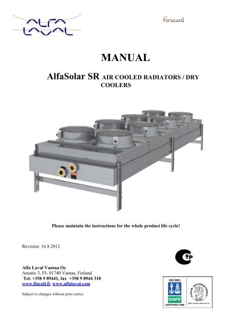
<strong>MANUAL</strong><strong>Alfa</strong>Solar SR AIR COOLED RADIATORS / DRYCOOLERSPlease maintain the instructions for the whole product life cycle!Revision: 16.8.2012<strong>Alfa</strong> <strong>Laval</strong> Vantaa OyAnsatie 3, FI- 01740 Vantaa, FinlandTel. +358 9 89441, fax +358 9 8944 318www.fincoil.fi; www.alfalaval.comSubject to changes without prior notice.
TABLE OF CONTENTTABLE OF CONTENT ....................................................................................................................... 11 PRODUCT SPECIFICATION .................................................................................................... 2GENERAL ..................................................................................................................................................................... 2NOTE ! ...................................................................................................................................................................... 21.1 TECHNICAL DATA ............................................................................................................................................... 21.2 IDENTIFICATION OF PRODUCT ........................................................................................................................ 21.3 PRODUCT SAFETY ............................................................................................................................................... 21.4 TERMS USED IN THE <strong>MANUAL</strong> ........................................................................................................................ 12 TRANSPORT AND STORAGE ................................................................................................. 12.1 PACKING, CONTENTS AND HANDLING OF PACKAGE ................................................................................ 12.2 STORAGE ............................................................................................................................................................... 22.3 TURNING AND LIFTING THE UNIT .................................................................................................................. 32.4 DISCHARGE AND RECYCLING OF PACKING MATERIALS ......................................................................... 43 INSTALLATION INSTRUCTIONS ........................................................................................... 53.1 PLACING ................................................................................................................................................................ 5Placing of a unit with horizontal air flow .................................................................................................................. 5Placing of a unit with vertical air flow ..................................................................................................................... 63.2 INSTALLATION REMARKS ................................................................................................................................ 73.3 SET-UP FOR INSTALLATION ............................................................................................................................. 73.4 TUBE CONNECTIONS .......................................................................................................................................... 8Dry coolers ................................................................................................................................................................ 83.5 FANS AND FAN CONNECTIONS ........................................................................................................................ 83.6 FANS´ POWER VALUES ...................................................................................................................................... 93.7 OPTIONS ................................................................................................................................................................. 9Water spraying system (KW) .................................................................................................................................... 9Stepwise and stepless (SVC) fan speed control ...................................................................................................... 10Vibration dampers (VD).......................................................................................................................................... 113.8. CHECKINGS BEFORE START-UP ................................................................................................................... 114 SERVICE INSTRUCTIONS ..................................................................................................... 124.1 SERVICE INSPECTION ....................................................................................................................................... 124.2 HEAT TRANSFER SECTION .............................................................................................................................. 124.3 HEAT TRANSFER SECTION .............................................................................................................................. 124.4 REPLACING THE FAN BLADE ......................................................................................................................... 134.5 REPLACING THE FAN MOTOR ........................................................................................................................ 135 DISCARDS AND RECYCLING .............................................................................................. 145.1 RECOVERY OF REFRIGERANTS ..................................................................................................................... 145.2 DEMOLISHING THE UNIT ................................................................................................................................. 145.3 MATERIAL RECYCLING AND DISCHARGING ............................................................................................. 146 ADDITIONAL REMARKS ...................................................................................................... 147 TROUBLESHOOTING ............................................................................................................. 158 ELECTRICAL SAFETY CHECKLIST .................................................................................... 178.1 LOCKOUT AND TAGOUT ................................................................................................................................. 178.2 DIAGNOSING A PROBLEM WHERE POWER IS REQUIRED ....................................................................... 178.3 TOOLS AND EQUIPMENT (PPE) ....................................................................................................................... 179 DECLARATION OF CONFORMITY ...................................................................................... 18Declaration by the manufacturer of the component incorporated to the machinery (Directive 2006/42/EC, Annex II,sub.B) ........................................................................................................................................................................... 181
1 PRODUCT SPECIFICATIONGENERALNOTE !Please follow these instructions to guarantee safe and correct installation, service and use ofradiators (SR). Persons, who are responsible for installing, using or servicing <strong>Alfa</strong>Solar radiators,must be familiar with the installation and service instructions. Please do not change or repair theunit without the manufacturer´s permission and instructions! The neglect to follow the instructionsmay result in warranty expiration.<strong>Alfa</strong>Solar SR radiators are designed for outdoor use in commercial and industrial refrigeration plants usingrefrigerants and solutions, which do not corrode copper.To avoid outer corrosion on heat transfer section always make sure that material of fins and heat transfertubes is suitable for ambient conditions. The air may not include any particles, which together withcondensing water or any other solvent might form corrosive combinations on fins or heat transfer tubes.The manual also concerns non-standard models with different specialties and options like double circuiting,forced draught fans (FD), higher mounting legs, etc. In these cases please always check from the deliverydocuments, in which way the difference has to be taken into notice in installation, service and use.1.1 TECHNICAL DATAPlease see the product leaflet for technical data, product designation, performance data, lifting/fixing pointsof fan motors, weights, internal volumes, position of connections!1.2 IDENTIFICATION OF PRODUCTPlease check the identification data on the product nameplate! This nameplateis located at the end with inlet connections. The product nameplate includescontact information of the manufacturer, product designation, number of orderacknowledgement, technical data of fan motor, operating/test pressure,min/max operating temperature, internal volume, weight, month/year ofmanufacture and CE marking.Fig. 1.1: Picture on the left shows the product label.1.3 PRODUCT SAFETYEach fan is equipped with fan guard and a lockable safety switch (except standard units with SVC). The wirespacing in the fan guard and the safety distance of the blade correspond to the safety standard concerningpersons over 14 years. The safety guards are protections from contact only; please do not stand on them!It is not allowed to climb on the coolers. If necessary, e.g. due to service operations, to climb on the unit, thefans have to be electrically isolated and reliably locked into off-position.The units must always be installed in a place with no entrance of outsiders.Please be very careful with lifting and transferring the units packed in an upright position. DANGER OFFALLING, see item 2 TRANSPORT AND STORAGE.2
Before lifting please check from the transport documents or from the product nameplate the unit weight andmake sure that the lifting device, crane or truck are appropriate.The electric connections may be performed by an authorized electrician only.Before starting the installation/service please always read through item 8 SAFETY CHECKLIST OFELECTRICAL INSTALLATIONS.Before starting the service operation make sure that the electrical supply is reliably isolated; use lock-out/tagoutsystem!Before starting the service always check by voltmeter that the unit is electrically isolated and shut off.Before switching on the unit always make sure that everyone is on a safe distance from the unit.The refrigerant recovery of the SR units may be performed by an authorized contractor only.The electric motors may be scrapped by an authorized contractor only.1.4 TERMS USED IN THE <strong>MANUAL</strong>Warning and noteWARNING ! Includes information, the negligence of which might result in accident or fatality.NOTE !Includes information, the negligence of which might cause damage to unit,environment, assembly or service.Models according to air flow direction:Models with vertical air flow, fans in oneor two rows (see fig. 1.3 on the right)Models with horizontal air flow, fans in oneor two rows (see fig. 1.3 on the right)Fig. 1.3 Models according to air flow direction2 TRANSPORT AND STORAGE2.1 PACKING, CONTENTS AND HANDLING OF PACKAGEBefore starting the lifting please make sure that:manual is includednecessary advance control has been madelifting device has been checked and is functioning welldriver has the permission for lifting1
ground under the unit has enough bearing capacitymachine/device is correctly erected and horizontally installedsupport legs are in supporting positionlifting capacity of the device is sufficientoperators know, how to use the lifting device according to operation and safety instructionsthere are no electric or other cables near to the lifting placeworking area of the lifting device is sufficient and safethere are no obstacles or risks on the working areaBoth in upright and horizontal transport position the unit withvertical air flow is from its legs fixed into the wooden flat, legsinstalled in transport position. Lifting /turning lug, turning legand horizontal leg support are delivered loose in the samepackage. Lifting/turning lug and turning leg are included inthe package of the models packed in an upright position only.The unit with horizontal air flow, packed in an uprightposition, is fixed into the wooden flat from a mounting rail.The lifting lug is delivered loose in the same package.When lifting the package by forklift truck, please use thelifting point where the lengthwise centre of gravity is betweenthe forklifts, in the middle. When lifting a long unit, pleaseuse as wide lifting position as possible.Fig. 2.1 On the left: the unit packed in anupside positionOn the right: the unit packed in horizontalpositionNOTE !Be very careful when handling high units. Never place them on inclined or uneven plane due toDANGER OF FALLING!Please check that the unit is tied tightly enough to prevent moving during transport. Take care that theunit is not damaged through binding.2.2 STORAGEThe products may not be stored in humid outdoor spaces, where water may condensate in their fan motors orin the tubing of heat transfer section. The motor bearings may be damaged by the humidity. Long standinghumidity in the tubing of heat transfer section can cause formic acid corrosion. The units shall be stored indry spaces with even temperature. During long term storage the fan motors must be driven for at least 30minutes once a month.If the above mentioned storage conditions cannot be guaranteed, a continuous low voltage must be lead intothe motors to keep their surface temperature higher than the air dew point temperature.In humid conditions, where the unit will not keep dry, some “white rust” can exist on the zinc surface.The units shall be stored fixed on their packing flats.Do not keep the units stored on inclined or uneven plane.2
2.3 TURNING AND LIFTING THE UNITThe <strong>Alfa</strong>Solar radiators are transported in vertical position as standard.The units for horizontal installation (vertical air flow) must be turned at installation.Two turning supports with locking bolts (see figure 2.2) are included in the delivery of the <strong>Alfa</strong>Solarunits.Fig. 2.2 Turning supports (remove locking bolts before installation!)NOTE !Air cooled heat exchangers are fragile products, which makes them extremely sensitive to incorrecthandling during transport and positioning. The instructions given must be strictly complied with in orderto prevent the heat exchanger from being damaged during the lifting procedure.Lifting operations must at all times be carried by qualified personnel using approved lifting equipment.How to turn the unit:1. Lift the unit off the ground.2. Remove the transport pallet.3. Insert the turning support into the leg profile until it reaches the fitting bolts. Place the turning support beneathboth lifting eyes.4. Lock the turning support into the leg with a locking bolt (see figure 2.3).WARNING! Do not stay under the unit being hanged!3
Fig. 2.3 Turning supports placed correctlyNOTE !The minimum length of a lifting chain, when no lifting channel is used = distance of liftingpoints. Please see below table.UnitSRMDistancebetweenliftingpoints AmmUnitweightkgUnitSRDDistancebetweenliftingpoints AmmUnitweightkgUnitSRDDistancebetweenliftingpoints AmmUnitweightkg1A-3 1400 240 2B-3 3600 1300 6B-6 7200 34301A-4 1400 260 2B-4 3600 1600 6C-4 7200 33201B-4 1800 320 2C-4 4200 920 6C-5 8400 35902A-3 2800 480 3B-3 1800 990 6C-6 8400 38602A-4 2800 520 3B-4 1800 1110 7B-3 5400 31902B-4 3600 640 3C-4 2100 1370 7B-4 5400 34603A-3 1400 720 4B-3 3600 1490 7B-5 5400 37303A-4 1400 780 4B-4 3600 1670 7B-6 5400 40003B-4 1800 960 4C-4 4200 1830 - - -4A-3 2800 960 5B-3 5400 1980 - - -4A-4 2800 1040 5B-4 5400 2200 - - -4B-4 3600 1280 5C-4 6300 2770 - - -5A-3 4200 1200 6B-3 7200 2730 - - -5A-4 4200 1300 6B-4 7200 2970 - - -5B-4 5400 1600 6B-5 8400 3200 - - -Table. 2.1: Distance between lifting points. It is recommended to use a lifting channel.Models outside this list, non-standard models and copper coil (CU): check the unit weight from the productnameplate!2.4 DISCHARGE AND RECYCLING OF PACKING MATERIALSAll packing materials are suitable eitherfor recycling or for energy recovery.4
3 INSTALLATION INSTRUCTIONS3.1 PLACINGAir cooled radiators should be situated so that there is no obstruction to air flow and that no hot airrecirculation will occur.When choosing the installation site, please note that the air flow from the units should be away from windblowing against it. This concerns especially the models with horizontal air flow and with low rpm fans.When necessary, please use fairings.In dimensioning, the actual site temperature in the sun should be noticed. Please also note the effect of snowfor the installation level of the unit.Placing of a unit with horizontal air flow> B/2> BBB> B/2> 2 x BBB> BBB> B/2> B/2Fig.3.1 Placing of a unit with horizontal air flow5
Effect of wind direction> 2 x BB >BPlacing of a unit with vertical air flow> B> B / 2B > A / 4B> B / 2> A / 4 BAAFig. 3.3 Fans in one row, the wall higher than theunit heightFig. 3.4 Fans in two rows, the wall higherthan the unit heightTwo units with fans in one row ( B = 1630 mm ) can be installed side by side (please note the minimumdistances shown in fig. 3.3). The leg height should be checked – when necessary, the units should beinstalled on a platform.If the wall is lower than the unit, the minimum distance between the unit and the wall is 0.5 x the minimumdistance with a higher wall.If the units are surrounded by 3 or 4 walls, the minimum distances are longer and should be checkedaccording to amount of units and their air flow.In exceptional cases please contact the product supplier/manufacturer!6
3.2 INSTALLATION REMARKSBefore installation please check at site possible transport damages, especially those in heat transfersection. The supplier is not responsible for costs caused by equipment broken as result of faultyhandling.Check the bearing capacity of fixing points and support structures before installation (see the unitweights in product leaflets!).To ensure optimum air venting and drainage of dry coolers, the tubes of the heat transfer sectionshould be in horizontal position.Trouble-free operation of the dry coolers provides good air venting of the units. Use the ventingscrews on the headers for air venting of the heat transfer section. Please always follow theinstructions of the refrigerant supplier!Water circulated dry coolers shall be drained, when the ambient temperature is < 0°C. Standard drycoolers are not gravity drained. It is recommended to use frost-proof refrigerants in installations,where the ambient temperature can be lower than 0°C.Please always follow the instructions of the refrigerant supplier in installation, in performing thepressure test, in taking into use, operation and service.All soldering of the heat transfer section is made by hard solder (FOSCO 710/DIN8513/LAg2P).3.3 SET-UP FOR INSTALLATIONThe models with horizontal air flow can be installed directly to the installation site. Just remove the liftinglugs after lifting.When mounting a unit with vertical air flow, the legs are installed in correct height. If the unit is installeddirectly on a plane surface should the height of the legs from the surface to the lower edge of the unit be ca620 mm (see figure!). Please also install the legs´ horizontal supports (see fig. 3, 5).When the unit is installed on a basement, the legs can be installed in steady middle position (ca 420 mm),without any horizontal support (fig. 3.6).Horizontalsupport for legs~620~420Fig. 3.5 Installation with legs directlyFig. 3.6 Installation on basement7
3.4 TUBE CONNECTIONSThe external tubes shall be installed in a way that their weight, vibration or heat expansion will notstrain the tubes of the heat transfer section.Dry coolersVentingFluid inVentingFluid outFluid inDischargeFluid outDischargeFigure 3.9 Model with vertical air flowFigure 3.10 Model with horizontal air flow3.5 FANS AND FAN CONNECTIONSNOTE !Electric connections may be performed by an authorized electrician only.The fans are direct driven axialfans The fan motors are 3-phasesquirrel-cage motors built to theIEC standards, designed foroutdoor use and provided withcondensing water outlets, shaftseals and self-lubricating bearings.The motors are suitable for220...240V/380...420V 50Hzelectric network. Their protectionclass, except for condensing wateroutlet, is IP54 or IP55 as standard.The motors are prewired to thesafety switches (IP65).Please ask the dry coolermanufacturer about the technicaldata of the fan motors!Electric network 220...240V-connectionSafety switchMotor junctionboxYellow-greenBlueBlackElectric network 380...420VY-connectionBrownCoated w ithblack plastictubeFig. 3.11: Fans´ electrical connections: motor junction box andsafety switch8
3.6 FANS´ POWER VALUESThe product nameplate indicates the power values at +20ºC and–30ºC.For defining the set values of the overload protector, the powervalue at other temperatures might be required. It can be nearlylinearly calculated by using above mentioned points. Forexample, the power value corresponding to -10° C can becalculated by multiplying the power value corresponding to+20°C (from product nameplate) by coefficient (k) given in thediagram at–10°C.Fig. 3.12 : Motor power value depending ontemperature3.7 OPTIONSWater spraying system (KW)The water spraying system helps to even out the shortloading peaks in summer time.For the unit with fans in one row one water spray tubingwill be installed. The units with fans in two rows will beequipped with two water spray tubings.The loose tubing together with assembly instructions will bedelivered with the unit.Please assemble the tubing in numerical order and at theplace shown in the figure below. Carefully tighten the jointsand make sure that all nozzles are in the same direction.Turn the tubing to get the nozzle angle to correspond the fanspeed. Check the right nozzle angle in the table at right!Lock the tubing at its place. The water flow is 0,5 l / min forone nozzle, pressure 3 bar.1 Reduction joint 5 End tube2 Water nozzle 6 Distance tube3 T-connector 7 Plug + connector4 Double nipple 8 Clamp/ drill screwNOTE !The nozzles may be blocked up by limey water, which can also form an isolating layeron the surface of the heat transfer section.Wrong pH-value of water may damage the heat transfer section. The pH-value shallvary between 7...8.NOTE !The water tubing may be broken due to freezing water. The tubing shall always bedrained after use by opening end plug (no. 7).9
Stepwise and stepless (SVC) fan speed controlSVC fan speed control has been pre-configured and test run at the factory including test-run of the fans andinspection of the regulator.See the leaflets of <strong>Alfa</strong> <strong>Laval</strong> Vantaa´s Step Control (SC) and SVC!The necessary documentation for the control system is included in the delivery (within the terminal box).The cables corresponding to the EMC standard have been connected to the unit end. Please see thenormative cable lengths in the table 3.1! The lengths might be different when using special equipment orspecial cables. In case the model type is not listed below, please contact to <strong>Alfa</strong> <strong>Laval</strong> Vantaa for info.SRMThe cable lengths of models [m]Fan size ø 1200Fan size ø 900 mmmmCableMCMK,[m]SRDCableMCMK,[m]SRDCableMCMK,[m]1A-3 3 2B-3 15 2B-3 81A-4 4 2B-4 17 2B-4 101B-4 4 2C-4 19 2C-4 112A-3 8 3B-3 27 3B-3 152A-4 9 3B-4 32 3B-4 182B-4 10 3C-4 36 3C-4 193A-3 14 4B-3 42 4B-3 233A-4 16 4B-4 51 4B-4 273B-4 18 4C-4 57 4C-4 304A-3 21 5B-3 60 5B-3 324A-4 26 5B-4 74 5B-4 394B-4 29 5C-4 83 5C-4 445A-3 30 6B-3 82 6B-3 445A-4 37 6B-4 102 6B-4 545B-4 42 6B-5 114 6B-5 60- - 6B-6 102 6B-6 54- - 6C-4 102 6C-4 54- - 6C-5 114 6C-5 60- - 6C-6 114 6C-6 60- - 7B-3 107 7B-3 56- - 7B-4 133 7B-4 70- - 7B-5 133 7B-5 70- - 7B-6 133 7B-6 70Table 3.1 Cable lengths.10
Vibration dampers (VD)The suitability of the elastic vibration dampers, supplied by <strong>Alfa</strong> <strong>Laval</strong> Vantaa, has been ensured.Check the load weight to be damped and make sure that just the right dampers for this load areavailable. Pay attention to the weight distribution of the damping rubber!The vibration dampers are meant for vertical compression load. Check that the ground and thebasement of the unit to be damped are horizontal.When damping group of units, shall both the driving unit and the unit to be operated be placed on asimilar rigid basement.Vibration damper Deflection xx percentage from mmPlease check the ambient conditions at[mm]site:34 LV 10/_ _ 7,5...8 75...80% from 10 mmo Temperatures –35...+65°C 34 LV 16/_ _ 12...12,8 75...80% from 16 mm34 LV 24/_ _ 18...19,2 75...80% from 24 mmo Organic solvents are injurious 34 LV 40/_ _ 30...32 75...80% from 40 mmoOils might damage the damper´srubber partsWhen connecting eg. tubes to the unit to be damped, always use flexible connections to guaranteetrouble-free vibration damping, to prevent transmission of vibration to the tubes and vibration stresson the tubing. After installation please check the correct deflection of the dampers from the table 3.2.Take care that there is margin around the unit to be damped.Please ask the manufacturer for further instructions, when necessary.Table 3.2 Allowed deflection of the vibration damper3.8. CHECKINGS BEFORE START-UPThe heat transfer section has been pressure-tested and the electric safety of the unit has been measured at thefactory. The electric safety checking includes steady-state and insulation resistance measurement of theprotecting cable. The customer has to make all measurements and tests (including grounding resistancemeasurement) which are required in the operating country. Make sure that the unit is firmly in position. Check the fixing of mechanical parts. Check the suitability of the electric network. Check the electrical connections. After electric installations check that the fans rotate properly and that the air flow direction iscorrect. When the fans are running please check that there is no unusual noise or vibration in the unit.11
4 SERVICE INSTRUCTIONSNOTE !The electrical connections may be performed by an authorized electrician only.WARNING ! Before starting the service operations make sure that the unit iselectrically isolated and dead.4.1 SERVICE INSPECTIONTrouble-free operation of <strong>Alfa</strong>Solar SR radiators provides regular service to checkvisual condition of the units and fans, once a monthfixing of the units, fans, fan motors and fan guards, once a monthcleanness and visual condition of the heat transfer section, once a monthWhen the condenser/dry cooler capacity is stepwise controlled by changing the number of fans, therunning order of fans must be changed periodically.correct deflection of vibration dampers, each year (when needed, replace the vibration dampers bynew ones supplied by <strong>Alfa</strong> <strong>Laval</strong> Vantaa Oy)4.2 HEAT TRANSFER SECTIONThe heat transfer section needs regular service if the unit is operated in dirty conditions. The dust gatheredon fins can be vacuum-cleaned (industrial vacuumcleaner)on air inlet side, or the fins can be washedwith water, preferably against the air flow.Washing can be done by running water, withoutusing pressure. Water must be directed onto the heattransfer section, against the air flow direction insidethe unit. The water jet may not be too strong, and itmust be directed perpendicularly to the fins´ side toprevent them bending or damaging Do not use anystrong alkaline detergents/solvents and acids, ordangerous, inflammable or environmentallydangerous detergents!The pH value of the washing water must be between7…8.Figure 4.1 Allowed angle of low pressure cleaningwater jet against the coil materialWARNING ! Before washing the heat transfer section, read the Material Safety Data Sheetof the detergent and follow the manufacturer´s instructions!When vacum-cleaning and washing, use protection glasses, safety gloves, safety shoes andother personal protection!henkilökohtaisia suojaimia.4.3 HEAT TRANSFER SECTIONPlease always check the motors, when performing service operations!Should the fan make any unusual noise, please stop it immediately, and check the fixing of the fan and fanmotor. When necessary, replace the motor by a new spare part motor supplied by <strong>Alfa</strong> <strong>Laval</strong> Vantaa.NOTE !During stand-stills the fans must be operated for 3…4 hours at least once a month.12
4.4 REPLACING THE FAN BLADEWARNING ! Before changing the fan blade make sure that the unit is electrically isolatedand that the motor is dead!Remove the fan guard by unscrewing the fixing screws.Remove the fan blade by unscrewing the locking screw.Pull out the fan blade with an extractor.Clean and lubricate the shaft.Place the new blade into the shaft (do not forget the wedge!).Do not knock the blade into the shaft, the motor bearings easily damage.Stroke at the shaft end HI-TEMP 343 RTV silicone rubber sealing spray,according to the instructions.Place a washer at the shaft end, on the silicone rubber sealing. Lock the blade hubby a fixing screw into the motor axle by using torque strong enough. Whentightening the fixing screw, some sealing compound presses out through thewasher edge and hole. This shows that enough silicone rubber sealing spray hasbeen used.Silicone rubber sealing spray prevents the water running along the joint between the blade hub andthe motor shaft into the motor.Place the fan guard.After installation make a test-run for the fan and check the fan visually.4.5 REPLACING THE FAN MOTORNOTE !The electric motor may be changed by an authorized electrician only.WARNING ! Before changing the fan motor make sure that the unit is electrically isolated andthe motor is dead. Switch off the current from the safety switch and close the switch. (Lockout and Tagout) Remove the fan guard (2) Remove the fan blade (see item 4.4 REPLACING THE FAN BLADE). Open the junction box and make sure that the motor is dead . Remove the electric cable. Unscrew four fixing screws of the fan motors . Lift up the fan motor. Install the new fan motor in reverse order. Install the fan blade (see item 4.4 REPLACING THEFAN BLADE). Check the minimum blade point gap: for fan Ø914 it is3 mm, and for fan Ø1240 the minimum point gap is5 mm. Place the fan guard. After installation make a test-run for the fan to checkcorrect rotation direction and its function in general. Please always use spare part motors supplied by <strong>Alfa</strong> Fig. 4.3 Fan unit :safety switch, :fan<strong>Laval</strong> Vantaa to guarantee their applicability to operating guard :junction box, : fan´s lockingconditions.screw and :motor´s fixing screw13
5 DISCARDS AND RECYCLINGWARNING ! Before discarding and demolishing the unit make sure that the unit is electrically isolatedand dead.5.1 RECOVERY OF REFRIGERANTSNOTE ! The refrigerant recovery of condensers may be performed by an authorized contractor only .The manufacturer´s instructions shall always be followed in handling and recovery of therefrigerants.NOTE !In demolishing the unit and in recovery, recycling and discarding of refrigerants,components and materials shall the local, national and international regulations befollowed.5.2 DEMOLISHING THE UNITRemove the unit from the installation site and transfer it to the place of demolishing. Please followthe instructions for lifting the unit.Turn the unit with horizontal air flow into horizontal position by paying attention to the liftinginstructions.Remove the fans, fan motors and cables.Remove the fan plate, legs and side plates.Remove the headers from the heat transfer section by cutting off the connection tubes.5.3 MATERIAL RECYCLING AND DISCHARGING Sheet metals, Fe + Zn – to steel scrap Heat transfer section, Cu-tube / Al--fin– to mixed copper scrap Header, Cu – to copper scrap Fan collar / motor bracket, Fe + Zn – to steel scrap Fan guard, Fe + Zn to steel scrap Motors recycling / scrapping (authorized contractor). Safety switches, cables recycling / scrapping (authorized contractor) Water jet tubing, Cu – to copper scrap6 ADDITIONAL REMARKSNOTE !Venting/draining valve of SR standard radiators is not adapted for heat transfer fluidsbased on potassium formiate; DANGER OF LEAKAGE!When using heat transfer fluids based on potassium formiate please always checkfrom the documentation that the piping system and venting/draining valves of the heattransfer section are adapted for the heat transfer fluid in question.Please follow the instructions of the heat transfer fluid supplier at installation,pressure-testing, starting-up, operation and maintenance.14
7 TROUBLESHOOTINGTrouble Reason What to doShort of capacity Refrigerant flow too low Check the valves/filters!Leakage in system / coil blockThe wrong flow direction in thecircuitingAir in systemFan/fans do not operate.Heat transfer section blocked up/dirtyIncoming air flow too lowWrong fan rotation directionInlet air too warmCheck the connections, brazings in heat transfersection and the tubing. When there is leakage inthe heat transfer section, please take contact withthe manufacturer for further repair instructions!See chapter 3.4 Tube ConnectionVentilate the system!Localize the problem, repair it or change the fanunit.Vacuum-clean/ wash the heat transfer sectionCheck the minimum distance between the unit andthe hinderances (see item 3.1 Location)Make sure that there are no obstacles for the airflow.Wrong phase sequence. Change the connection onmotor coupling or from the switch board.Check the location of the units (item 3.1). Shadethe unit from the sun! Heat transfer capacity can beincreased by water jet system.Vibration in the unit Broken fan Repair/ change the fan!Damaged vibration dampers Install new vibration dampers, check the correct…Fan does not start Fan is frozen in the fan collar Remove iceThe fuse has blown outReplace the fuseOverload releaseCheck and reset from the overload release switch!Wrong supply voltageWrong connectionCheck that the supply voltage corresponds to thevalue marked on the motor sign.Check the connections from the item ”Motorconnections” and from the product nameplate.Break in coil or in control circuitIf the switch is in off-position, there will bebumbling noise. Check the slack line switches!Check that the line switches close.Mechanical failureCheck that the fan motor and fan blade rotatefreely. Check the bearing and lubrication!Short circuit in coilCan be indicated by a blown-out fuse. The motorhas to be replaced.One phase in the motor can be Check the connection!broken.Fan stops. Voltage break Blown-out fusesLow voltageCheck that the voltage given the productnameplate is followed. Check the connections!Trouble Reason What to do15
Fan starts, then stops Failure in supply voltage Check the loose connections, fuses and controlcircuit.Fan does not reach themaximum speedWrong fan motor typeToo low voltage at the fan motorterminals because of voltagedrop.Ask the supplier about a correct type of fan.Use higher voltage or a starter transformer. Checkthe connections and the correct cable size.Broken rotorCheck eventual breaks in short-circuiting ring.Generally, a new rotor or motor is neededMotor takes high amp. Too low voltage Check the size of cables on basis of voltage drop.Too low supply voltageCheck the supply voltageWrong rotation direction Wrong sequence of phases Change the connection on motor coupling or fromswitchboard..Fan motor overheating. Motor body or cooling openingsmay be dirty or blocked-up,Clean the motor and and ensure trouble-free aircirculation.therefore hindering proper motorventilation.One motor phase may be open. Check the connection.Earth faultIdentify and repairAsymmetric supply voltage to Check the cables and connections.motor terminalVibrating fan Loosen motor fixing Tighten the fixing screws and check the alignmentUnbalanced fan blade/Fan blades Balance the blade or change it.misalignedFaulty bearingsChange the bearings3-phase motor running as single Check the connectionsphaseToo big axial playCheck the bearingsAbrasive noise in fanFan blade is chafing against fancollar.Motor ventilator is chafingagainst the cover.Check the motor centering and fixing.Repair the fan/cover.Exceptionally heavy noiseof runningVentilator hits on insulation.Motor has got loose from itsfixing.Air gap not centralized.Prevent the touch.Tighten the fixing bolts and rebalance the fan.Check steering turning and bearings.NOTE !The motor may be discharged and assembled by a skilled mechanician only byusing proper tools and approach. The repair work shall be performedaccording to the standard IEC-60079-19.Under guarantee period the faulty motor must always be returned to thesupplier (do not demolish it!).Please always use the spare part motor supplied by <strong>Alfa</strong> <strong>Laval</strong> Vantaa toguarantee its applicability to operating conditions.16
8 ELECTRICAL SAFETY CHECKLISTAll service, maintenance, repair, controls and installation employees must have this list with them at everyjob and read through it before they start the job.These are the minimum requirements. If you cannot meet these requirements, you cannot start the work8.1 LOCKOUT AND TAGOUT1. Notify affected persons of the shut down.2. Shut down the equipment by the normal process.3. Disconnect and lock and tag all energy sources.4. Released any stored energy (capacitors, transformers, etc.).5. All employees working on the equipment must have theirown personal lock in placetulee olla oma lukitus asetettuna paikoilleen.6. Prior to servicing equipment a check must be made with a”proximate voltage sensor” to ensure that the frames orcontrol enclosures of equipment being serviced are notenergized.7. Check that circuit-testing devices are workingLockout/TagoutVerify with a testingdevice8. Verify the absence of electrical current or voltage with a circuit-testing device; use insulated glovesand an insulated mat.9. Notify affected persons of the return of electrical power.8.2 DIAGNOSING A PROBLEM WHERE POWER IS REQUIRED1. Remove all conductive clothing or accessories.2. Do not use any conductive equipment or tools.3. Use insulated tools and safety glasses4. Do Not work on electrical circuits greater then 600 voltsunless you have received specific training5. Suspend work or have a shelter during adverse weatherconditions.6. Use a certified insulated mat to stand on while doing thetesting.7. Use certified electrical insulated gloves while doing thetesting.8. After diagnostic work is completed and service work isrequired you must complete logout and tagout.UseinsulatedtoolsUseGFCI8.3 TOOLS AND EQUIPMENT (PPE)Ensure that electrical equipment you are working on isgrounded.Ensure that electrical power tools are double insulatedor have a ground plug.Use Ground Fault Circuit Interrupters (GFCI).Inspect power tools, insulated hand tools and electricalcords for damageDamaged tools and cords shall not be used.Do not use conductive equipment e.g. metal ladders.Wear PPE17
9 DECLARATION OF CONFORMITYDECLARATION BY THE MANUFACTURER OF THE COMPONENT INCORPORATEDTO THE MACHINERY (DIRECTIVE 2006/42/EC, ANNEX II, SUB.B)ALFA LAVAL VANTAA OYAnsatie 3, FI-01740 Vantaa, Finlandherewith declares that the componentSJ, SCA, SCAL, SCCL, SEpL, SX, SC air cooled condenserSJG, SCAG, SCCG, SEpG, SXG, SD, SR air cooled dry coolerwhich is not able to function independently is intended to be incorporated into machineryor to be assembled with other machinery to constitute machinery covered by Directive2006/42/EC and changes related to it and with national implementing legislation meantmachinery.By designing of the component the following directives have been applied:2006/42/EC, 2004/108/EC, 97/23/ECand the following harmonized standards have been applied:ISO 12100:2010, SFS-EN ISO 13857, SFS-EN 14276-2+A1,SFS-EN 60204-1, SFS-EN, 61000-6-1, SFS-EN 61000-6-3,SFS-EN 61000-6-4and furthermore declares that is not allowed to put the machinery into service until themachinery into which it is to be incorporated or of which it is to be a component has beenfound and declared to be in conformity with the provisions of Directive 2006/42/EC andwith national implementing legislation including the machinery referred to in thisdeclaration.Vantaa, May 25, 2012Silja BeierschoderQuality Manager18