6.4 Clamp Mechanism Maintenance and Replacement<strong>8530</strong> <strong>Shatterbox</strong>All <strong>Shatterbox</strong>es have clamp levers that are anchored to the capsule retainer by yokes. Incurrent <strong>Shatterbox</strong> models (8500, 8515, <strong>8530</strong>), the yokes are attached with Allen bolts insertedfrom the top, so they can be tightened easily if the yokes become loose. Instructions are givenhere for tightening and replacing yoke bolts, and for replacing clamp arms and levers.If one of these bolts breaks and cannot be removed from the capsule retainer, or you arerepairing an earlier model <strong>Shatterbox</strong> with the yoke bolts inserted from beneath, call ourService Department for advice and parts availability. Contact information is in Section 12.0.The <strong>Shatterbox</strong> clamp mechanism is anchored to the capsule retainer by yokes: the long yoke(Diagram A, Item 19) holds the clamp arm (Diagram A, Item 14), and the short yoke (Diagram A,Item 12) holds the clamp lever assembly (Diagram A, Item 13). Each yoke is attached to thecapsule retainer by two Allen bolts (Diagram A, Item 10). If a yoke loosens, the bolts must betightened. To do this, remove the C-clip (Diagram A, Item 18) from one end of the pin (DiagramA, Item 17) that holds the clamp arm or lever, and push the pin out from that end. Use a 5/32-inch Allen wrench to tighten the loose bolts; you may wish to remove the bolts, clean them,and apply a locking agent before tightening them.Clamp arms and clamp levers are replaced in a similar way, by pushing the pin out of the yoke,removing the old arm or lever, replacing it, re-inserting the pin, and holding the pin in placewith a C-clip.6.5 Tightening or Replacing the YokesAll but a few of the early <strong>Shatterbox</strong>es have a long yoke (Diagram A, item 19) and swing shortyoke (Diagram A, item 12) that are fastened to the capsule retainers by Allen bolts insertedfrom above. If these bolts loosen, they can be tightened with an Allen wrench after removingthe pin holding the clamp arm or lever. To do this, remove one of the C-clips (Diagram A, item18) holding the pin (Diagram A, item 17) in place, and push the pin out from that end. In theunlikely event that the bolts shear and cannot be removed from above, or if you have one ofthose early <strong>Shatterbox</strong>es with the bolts inserted from below, it will be necessary to remove thefunnel to gain access to the underside of the capsule retainer. After detaching the uppersection of the mechanism (Diagram A, item 18 from item 22), invert it and remove the eccentricarm (Diagram B, item 35) by first taking out the small setscrew from the large slotted setscrew(Diagram B, item 27) and removing it. Then pull the funnel straight off the shaft. Wheninstalling either yoke, first clean the yoke and its mounting bolts to remove all traces of oil, andtreat each bolt with a locking agent to prevent loosening after assembly. When replacing thefunnel and eccentric arm make sure that the long side of the eccentric arm and the funnelcounterweight (Diagram A, item 9) are on the same side of the funnel, otherwise the gyratingmotion of the <strong>Shatterbox</strong> will be unbalanced.Page 18 of 28 <strong>SPEX</strong> <strong>SamplePrep</strong> LLC January 2010
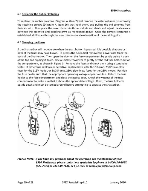
6.6 Replacing the Rubber Columns<strong>8530</strong> <strong>Shatterbox</strong>To replace the rubber columns (Diagram A, item 7) first remove the older columns by removingthe retaining screws (Diagram A, item 26) that hold them, and pulling the old columns fromtheir sockets. Then place the new columns in those sockets and check and adjust the clearancebetween the eccentric and coupling arms as mentioned above. Once the correct clearance isestablished, drill holes through the new columns to allow insertion of the retaining pins.6.6 Changing the FusesIf the <strong>Shatterbox</strong> will not operate when the start button is pressed, it is possible that one orboth of the fuses may have blown. To access the fuses, first remove the power cord from theback of the <strong>Shatterbox</strong>. Then open the door on the fuse compartment by gently prying it openat the top and flipping it down. Use a small screwdriver to gently pry the red fuse holder out ofthe compartment, as shown in Figure 3. Remove the fuses and check them using a continuitytester. If either fuse is blown or defective, replace both with 3AG 10-amp, 230V slow-blowfuses for the 115V model, or 3AG 5-amp, 230V slow-blow fuses for the 230V model. Positionthe fuse holder such that the appropriate operating voltage appears on top. Return the fuseholder to the fuse compartment and close the access door. Check the window of the fusecompartment to make sure that it shows the appropriate voltage. If not, the fuse holder isupside down and must be turned around before attempting to operate the <strong>Shatterbox</strong>.PLEASE NOTE: If you have any questions about the operation and maintenance of your<strong>8530</strong> <strong>Shatterbox</strong>, please contact our specialists by phone at 1-800 LAB-<strong>SPEX</strong>(522-7739) or 732-549-7144, or by e-mail at sampleprep@spexcsp.com.Page 19 of 28 <strong>SPEX</strong> <strong>SamplePrep</strong> LLC January 2010