INSTRUCTIONS MANUAL - Alfa Laval - ABC
INSTRUCTIONS MANUAL - Alfa Laval - ABC
INSTRUCTIONS MANUAL - Alfa Laval - ABC

Create successful ePaper yourself
Turn your PDF publications into a flip-book with our unique Google optimized e-Paper software.
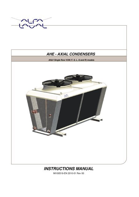
AHE - AXIAL CONDENSERS<strong>Alfa</strong>V Single Row VCM (T, S, L, Q and R) models<strong>INSTRUCTIONS</strong> <strong>MANUAL</strong>IM100519-EN 2010-01 Rev 00
Index• To the User ................................................................................. 3• System Warranty ....................................................................... 3• Safety ......................................................................................... 4• General Description .................................................................. 6Codification Way: ...................................................................... 6Product Range: ......................................................................... 7Reception ................................................................................... 8Storage ....................................................................................... 8• Provisions for Mounting ........................................................... 8Layout ......................................................................................... 8Bases .......................................................................................... 9Lifting Procedure ..................................................................... 10• Mounting .................................................................................. 11Vibration isolators ................................................................... 11Piping Connections................................................................. 12Electrical options ..................................................................... 13• Operation ................................................................................. 14Starting the Condenser .......................................................... 14• Maintenance ............................................................................. 15Periodic preventive controls .................................................. 15Cleaning the equipment ......................................................... 15Tools and accessories for maintenance ............................. 16Troubleshooting: ..................................................................... 16Disassembling the fan motor ................................................ 17Replacement of Fan Motor .................................................... 17How to contact <strong>Alfa</strong> <strong>Laval</strong>The contact information for each country is constantly updated in our website.Visit www.alfalaval.com to get this information.TH E TECHNICAL INFORMATION SUPPLIED AND OTHER MINOR CHANGES CAN BE MODIFY WITHOUT NOTIFICATION2
SafetyThe hazardous operations and other important information are emphasized in this section. The warningsare highlighted by means of special signs.Always read this manual before using the equipment!ATTENTION!people.BE CAREFUL!NOTE!Indicate that special procedures must be followed to avoid serious injuries toIndicate that special procedures should be followed to avoid serious damages tothe equipment.Indicate important information to simplify the operations or to make them moreunderstandable.Warning signs:In this page all the warning signs of this manualare summarizedGeneral precaution signDanger loads in movement signDanger parts in movement signElectrical danger signImportant information4
Pay attention to the following instructions to avoid serious injuriesto people and / or damages to the equipment.Operation for the transportation of the equipmentLifting OperationATTENTION!Before lifting the equipment• Attach the belts or hooks, only to the provided elements theequipment is equipped with.• Be sure that the belts or the slings with hooks will lift the equipment ina balanced way.Installation and maintenance operationsATTENTION!Before performing any maintenance operation, the power supply from thegeneral board should be switched off, and the safety switch should be in theOFF position to avoid accidents.ATTENTION!For no reason, a person should walk or step over the equipment, sincebesides the damage, it can generate an accident or a risky situation.ATTENTION!Whenever Fans maintenance task should be carry out, be sure they are notrunning and the security switch is in the OFF position. When the operation iscompleted, place back the corresponding protection.5
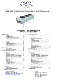
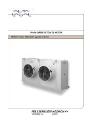
General DescriptionThanks to the combination of the innovative waviness of the fins (designed by <strong>Alfa</strong> <strong>Laval</strong>) and the use of copperpipes for fluid flow, the heat exchanger guarantees an excellent heat transfer.The heat exchanger is built with aluminum sheets and copper tubes that goes together to the collectors, 2.1 mm.is the standard space between fins.The fan motors are class IP 54 according to DIN 40050.The cabinet is built in galvanized steel sheet, pre-painted with an epoxy finish (RAL9002).Separated fan sections are provided.Codification Way:Code <strong>Alfa</strong>V Single Row Condenser6
Product Range:7
ReceptionThe equipment is normally shipped as it is, without any kind of pallet and wrapped with nylon.The condition of the unit should be verified at the moment of reception: the equipment left the factory in perfectcondition; eventual damages should be claimed immediately to the transportation company in writing in theDocument of Delivery before being signed. <strong>Alfa</strong> <strong>Laval</strong> or its Agents should be informed as soon as possible aboutthe significanceof the damage. The Client should complete a written report including photographs concerning each relevantdamage.StorageIf the equipment has to be stored before its installation (one or more months) it is convenient to take the followingprecautions:• Leave the equipment in its packing.• Store it indoors, in a room with adequate conditions, temperature (15 to 25 º C) and humidity (50 to 70%).• In an environment without corrosive liquids or vapors.Provisions for MountingLayoutThe following aspects should be considered before mounting:• Verify the structure supporting capacity regarding the weight of the equipment.• Avoid the installation in closed locations.• When walls are present, follow the distances recommended by <strong>Alfa</strong> <strong>Laval</strong>.8
• Special care should be taking in following the minimum distances recommended, particularly in cases forinstallations with two or more units in areas with strong winds.BasesFan Diameter A [mm] B [mm] C [mm]800mm 800 1000 500910mm 900 1100 500To avoid the oxidation of the equipment's legs, it is recommended to lean them on concrete bases (one base foreach leg) of about 4 inches (10 cm.) high and 2 inches (5 cm.) exceeding the equipment leg.Verify that the lifting components support the equipment weight plus 10%, beforeperforming any lifting task.9
Lifting Procedure10
MountingVibration isolatorsFor active and passive isolation of vibrations and reducing noise transmission, <strong>Alfa</strong> <strong>Laval</strong> strictly recommends theinstallation of anti-vibration dampers.MATERIALIsolator: Natural rubber 60° ShA..Frame: Galvanized steel, with yellow Zinc treatment.Install the anti-vibration attachment between the equipment and the base. (For Horizontal mounting)Mounting schemeFanDiameterCod.60626227Cod.60626031ScrewWeightminWeightmaxM10 - 200daNM12 210da 335daN N11
Piping ConnectionsCondensers:The equipment is delivered with the followingconnections BW Type Cooper tube connection forwelding.The following diagram shows the recommendedinstallation:1. Anti-vibration device.2. Silencer.3. Condenser.4. Liquid receiver.5. Thermal expansion valve.6. Evaporator.7. Compressor.ImportantSize the pipes to minimize the pressure drop and to obtain the coolant speed valuesto assure the oil drifting. In the drive line, between the compressor and the condenser,install an anti vibration device (1) and a silencer (2) to reduce the noise and vibrationtransmission along the line.Be sure that the line for liquid should have a minimum gradient of 1%, between theliquid discharge and the receiver.Important!Before making the connections, verify the presence of thepreloaded nitrogen for the dry maintenance of the circuit. In themulti- circuit condensers the refrigerating lines goes from the LEFTto the RIGHT (H version) or from above to down (V version).Welding the pipes:To weld the external piping to the equipment,(cooper pipes) an overlapped welding is suggested,for the double purpose of assuring the staunchnessand reducing the breaking risks in the welded area,generated by inducted vibrations.If the diameter of the pipes don’t allow this solution,special female threaded unions should be used.12
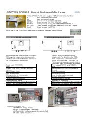
Before making the welding, disassembly the cap-label of the ½ ”gasvalve and eliminate the preloaded nitrogen completely.Electrical optionsAttention:To carry out safe maintenance operations, an ON / OFF Switch should beinstalledclose to the equipment.Safety switch ON / OFFAuxiliary contacts: 2Rated current: 16 AVoltage protection: 600 voltsCable: VDE 7030Protection class: IP 65GroundingAttention: The ground connection is required by law.The ground connection should be made through a cable from the motor's frame to the equipment structure andfrom structure to the plant ground.Attention:Ground resistance should be lower than 3 ohmsElectrical fan motorThe fan motors have the following specifications:• Type: Induction squirrel cage• Protection type: IP 54• Insulation type: F class• S1: Continuous duty• Sealed ball bearings for thermal range from –40 to 100°C• Connectiono 3 Phase – 400 V + - 10% 50 Hz.o Single phase - 230 V + - 10% 50 Hz.13
OperationStarting the Condenser• Carry out a vacuum phase by connecting to the coupling for equipment loading.• Load the system with cooling gas.• Start the system and make sure that there are no gas leaks.ShutdownWhen the unit should be emptied for maintenance or when the system is not in use, the following procedureshould be performed:• Isolate the equipment.• Collect the cooling liquid.• Disconnect the circuit and flush the equipment with nitrogen.When not in use, leave the equipment loaded with dry nitrogen.For the correct operation of the equipment, <strong>Alfa</strong> <strong>Laval</strong> original spares should beused.Attention!: Before attempting any maintenance operation, makesure that the power supply is properly disconnected.Attention: Before attempting to make any maintenance, the powersupply should be turned off from the sectional board. For furthersecurity, the operator can also turn the switch ON / OFF to theOFF position to avoid accidents.14
MaintenancePeriodic preventive controlsEvery three months the following controls should be performed:• Check the equipment fastening.• Verify that the electric connection terminal studs are properly tight, to avoid losses and wear due tosparks.• Verify the good condition of the wiring (it should not have cuttings or deterioration signs).• Check the electrical resistance of the ground connection (ohms).• Use an ammeter to check that the current absorbed is equal to or slightly lower than the rated value whenthe fan(s) work(s) at rated speed.If the equipment should remain without operation for long periods(three or more months), it is advisable to operate the fan(s), atleast once per month, during 3 to 4 hours each time.Cleaning the equipmentTo guarantee the thermal efficiency of the equipment, it is necessary to eliminate the dirt deposited in the coils, onthe suction side. A low pressure water jet or non aggressive liquids can be used.A cleaning is recommended every three months, but this frequency should be defined according with theenvironment where the equipment is installed.15
Tools and accessories for maintenance• Open end or combination wrenches kit (millimeters), (sizes from 10 to 20mm)• Open end or combination wrench kit (inches), (sizes from ½” to 2”)• Adjustable wrench (3” opening)• Oxyacetylene welding equipment• Current clamp tester• VoltmeterTroubleshooting:PROBLEM POSSIBLE CAUSE SOLUTIONCondensation pressure too highAir flow to condenser blockedby dirt on the coil with finsDefective fanWrong air flow directionthrough the coilClean the coil with water and adegreaser or non corrosive liquidReplaceInvert the rotating direction of thefan, switching two of the threephasesCondensation pressure too low Air temperature too low Adjust the condenser pressureregulationExcessive air flow through thecondenserFans not running Faulty motor ReplaceLine voltage lower thantolerance limitsCheck the voltage value betweenphases with a voltmeter.Lack of a phaseMeasure the voltage betweenphases, check the power supplylineOverloaded motorCheck with an AmmeterFan break Blockage or shocked Replace16
Disassembling the fan motorAttention: Before attempting to make any maintenance, the powersupply should be turned off from the sectional board. For furthersecurity, the operator can also turn the switch ON / OFF to theOFF position to avoid accidents.• Remove the fan protecting grid.• Loose the fastening stud bolts and remove the impeller, if necessary disassemble the whole group.• Disconnect the motor wires.• Remove the bolts that hold the group to the frame support.• If damaged, replace the impeller for a new one.• To facilitate the installation, before mounting the impeller, lubricate the shaft.• Place the impeller in position and tight the stud bolts.• Clean the inner side of the grid and mount it.Replacement of Fan MotorControl the correct operation of the electric fans periodically. In the event of electric or mechanical failures, themotor should be replaced as follows:• Make sure that the power supply has been switched off, by placing the security switch in the OFFposition.• Then, open the electric motor derivation box, disconnect and remove the electric wires.• Unscrew the fastening screws in the grid.• Loose the screws that hold the motor to the support and remove the impeller group- motor.• Place the impeller in the new motor shaft and install it.• Place the protection grid.• Make the electric connection.• Check the correct rotating direction.17