Chapter 3 Case Study
Chapter 3 Case Study
Chapter 3 Case Study

Create successful ePaper yourself
Turn your PDF publications into a flip-book with our unique Google optimized e-Paper software.
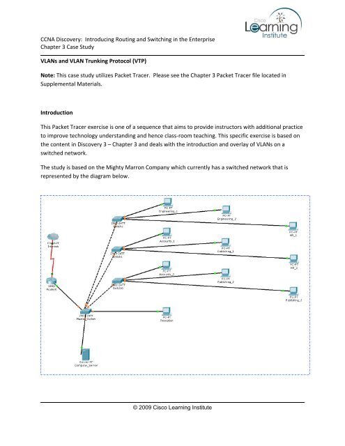
CCNA Discovery: Introducing Routing and Switching in the Enterprise<strong>Chapter</strong> 3 <strong>Case</strong> <strong>Study</strong>VLANs and VLAN Trunking Protocol (VTP)Note: This case study utilizes Packet Tracer. Please see the <strong>Chapter</strong> 3 Packet Tracer file located inSupplemental Materials.IntroductionThis Packet Tracer exercise is one of a sequence that aims to provide instructors with additional practiceto improve technology understanding and hence class‐room teaching. This specific exercise is based onthe content in Discovery 3 – <strong>Chapter</strong> 3 and deals with the introduction and overlay of VLANs on aswitched network.The study is based on the Mighty Marron Company which currently has a switched network that isrepresented by the diagram below.© 2009 Cisco Learning Institute
CCNA Discovery: Introducing Routing and Switching in the Enterprise<strong>Chapter</strong> 3 <strong>Case</strong> <strong>Study</strong>The Mighty Marron CompanyThe Company switched network is a single IP subnet (address: 192.168.100.0/24) and consequently, allusers in a single broadcast domain. However, you understand that this is not the most efficient use ofthe installed switch capabilities, as well as having negative security implications since all Companydepartments share a common switched domain.You know that the Cisco switches installed as part of the network support advanced VLAN capability,and you decide that you will update the network to take advantage of this.Task:You are required to setup separate VLANs for each of the four departments within the company withoutrequiring any physical rewiring of the current network. Users are required to be able to communicatewith each other, both within and between their respective VLANs. In addition, you will set up a VTPsystem between the switches.Detailed Instructions:The Company has four departments spread across a three story building. They are:• Engineering• Human Resources• Accounts• PublishingYou will set up the following VLANs for the various departments.EngineeringHumanResourcesAccounts Publishing NativeVLAN # 102 104 106 110 1NetAddress192.168.102.0/24 192.168.104.0/24 192.168.106.0/24 192.168.110.0/24 192.168.100.0/24© 2009 Cisco Learning Institute
CCNA Discovery: Introducing Routing and Switching in the Enterprise<strong>Chapter</strong> 3 <strong>Case</strong> <strong>Study</strong>The respective PC addresses to be assigned are as follows:Engineering Human Resources Accounts Publishing#1 192.168.102.100 192.168.104.100 192.168.106.100 192.168.110.100#2 192.168.102.101 192.168.104.101 192.168.106.101 192.168.110.101#3 192.168.104.102 192.168.110.102*Note that the Reception PC connected to the master switch is considered as part of the HR VLAN(HR#3).VTP SetupThe master switch is to be set up as the VTP server with a password cisco and domain name company.All other switches are to be set as VTP clients.The switch native VLAN addresses are set as:SwitchAddressMaster 192.168.100.13Ground Floor 192.168.100.12First Floor 192.168.100.11Second Floor 192.168.100.10(These instructions are repeated in the Packet Tracer file).After completing the switch and router configurations, ensure you can communicate between any twohost machines. Also ensure any host can reach the Web server at 192.168.100.50 and the (simulated)“WAN Interface” on the gateway router at 50.50.50.1.© 2009 Cisco Learning Institute