if sufficient web was present <strong>to</strong> transfer shear loads. InASTM C90-11b, these requirements were replaced witha single minimum web thickness (0.75 in., 19.1 mm),regardless of unit width. The equivalent web thicknesswas replaced with a normalized web area, a measure ofthe area of web contact with the face shells per squarefoot of wall (see Table 2).In 2000, the Type I (moisture-controlled) and TypeII (non moisture-controlled) unit designations wereremoved from C90. The designations were withdrawnbecause they were difficult <strong>to</strong> effectively use and enforce,and because of newly developed concrete masonry crackcontrol provisions. The new crack control guidelines arebased on anticipated <strong>to</strong>tal volume changes, rather than onthe specified moisture contents that formed the basis forType I requirements. Control joint criteria can be foundin References 5 and 6. For more detailed information onremoval of the Type designations, see the Frequently AskedQuestions section of the NCMA website (http://www.ncma.org/resources/design/Technical FAQ).Physical RequirementsPhysical requirements prescribed by ASTM C90 includedimensional <strong>to</strong>lerances, minimum face shell and web thicknessesfor hollow units, minimum strength and maximumabsorption requirements, and maximum linear shrinkage.Overall unit dimensions (width, height and length) canvary by no more than ± 1 / 8 in. (3.2 mm) from the standardspecified dimension. Exceptions are faces of split-face unitsand faces of slump units which are intended <strong>to</strong> provide arandom surface texture. In these cases, consult local suppliers<strong>to</strong> determine achievable <strong>to</strong>lerances. Molded featuresTable 2—ASTM C90-11b Minimum Face Shell &Web Requirements for Hollow Units (ref. 3) ANominalwidth ofunit, in.(mm)3 (76.2)&4 (102)Face shellthickness,min., in.(mm) B, CWebthicknessC in.(mm)WebsNormalizedweb area,min., in. 2 /ft 2(mm 2 /m 2 ) D3/ 4 (19) 3/ 4 (19) 6.5 (45.14)6 (152) 1 (25) 3/ 4 (19) 6.5 (45.14)8 (203) & 1 1 / 4 (32) 3/ 4 (19) 6.5 (45.14)greaterAAverage of measurements on a minimum of 3 units whenmeasured as described in Test Methods C140 (ref. 4).BFor units with split surfaces, a maximum of 10% of thesplit surface may have thickness less than those shown,but not less than 3 / 4 in. (19 mm). When the units are <strong>to</strong> besolid grouted, the 10% limit does not apply and Footnote Cestablishes a thickness requirement for the entire face shell.CWhen the units are <strong>to</strong> be solid grouted, minimum faceshell and web thickness shall be not less than 5 / 8 in. (16 mm).DMinimum normalized web area does not apply <strong>to</strong> theportion of the unit <strong>to</strong> be filled with grout. The length of thatportion shall be deducted from the overall length of the unitfor the calculation of the minimum web cross-sectional area.such as rib and scores must be within ± 1 /16 in. (1.6 mm) ofthe specified dimension and within ± 1 /16 in. (1.6 mm) ofthe specified placement on the mold. For dry-stack masonryunits, the physical <strong>to</strong>lerances are typically limited <strong>to</strong> ± 1 /16in. (1.6 mm), which precludes the need for mortaring,grinding of face shell surfaces or shimming <strong>to</strong> even outcourses during construction (ref. 7).Minimum face shell and web thicknesses are thosedeemed necessary <strong>to</strong> obtain satisfac<strong>to</strong>ry structural and nonstructuralperformance. Note that although there are someunique face shell thickness requirements for split-facedunits (see Table 2 footnote B), ground-face units (i.e., thoseground after manufacture) must meet the face shell thicknessrequirements contained in the body of Table 2. In addition<strong>to</strong> minimum permissible web thicknesses for individualwebs, the specification also requires a minimum <strong>to</strong>tal webcontact area with face shells per square foot of wall area.When evaluating this normalized web area, the portion ofa unit <strong>to</strong> be filled with grout is exempted. This provisionavoids excluding units intentionally manufactured withreduced webs, including bond beam units and open-endblock, where grout fulfills the structural role of the web.A solid unit is one with a net cross-sectional area inevery plane parallel <strong>to</strong> the bearing surface of at least 75%of the gross cross-sectional area measured in the sameplane. Minimum face shell and web thicknesses are notprescribed for solid units.The net area used <strong>to</strong> determine compressive strengthis the “average” net area of the unit, calculated from theunit net volume based on tests described in ASTM C140(ref. 4). Gross and net areas are shown in Figure 1.Net area compressive strength is used for engineeredmasonry design, taking in<strong>to</strong> account the mortar bedded andgrouted areas. Gross area compressive strength is still usedfor empirically designed masonry (IBC Section 2109).Maximum permissible water absorption is shown inTable 3. Absorption is a measure of the <strong>to</strong>tal water required<strong>to</strong> fill all voids within the net volume of concrete. It is determinedfrom the weight-per-unit-volume difference betweensaturated and oven-dry units. Aggregates with relatively largeGross area* (shaded) = width (actual) x length (actual)Net area* (shaded) =net volume (actual)height (actual)= (% solid) x (gross area)* For design calculations, a masonry element's sectionproperties are based upon minimum specified dimensionsinstead of actual dimensions.Figure 1—Gross and Net Areas2 NCMA TEK 1-1F
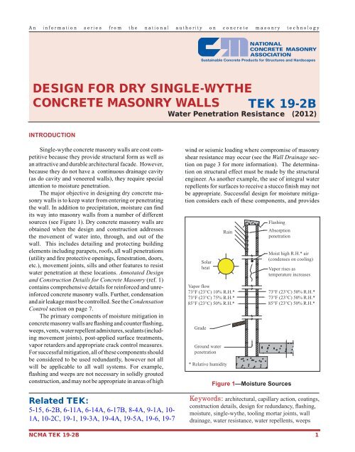
An information series from the national authority on concrete masonry technologyDESIGN FOR DRY SINGLE-WYTHECONCRETE MASONRY WALLS TEK 19-2BWater Penetration Resistance (2012)INTRODUCTIONSingle-wythe concrete masonry walls are cost competitivebecause they provide structural form as well asan attractive and durable architectural facade. However,because they do not have a continuous drainage cavity(as do cavity and veneered walls), they require specialattention <strong>to</strong> moisture penetration.The major objective in designing dry concrete masonrywalls is <strong>to</strong> keep water from entering or penetratingthe wall. In addition <strong>to</strong> precipitation, moisture can findits way in<strong>to</strong> masonry walls from a number of differentsources (see Figure 1). Dry concrete masonry walls areobtained when the design and construction addressesthe movement of water in<strong>to</strong>, through, and out of thewall. This includes detailing and protecting buildingelements including parapets, roofs, all wall penetrations(utility and fire protective openings, fenestration, doors,etc.), movement joints, sills and other features <strong>to</strong> resistwater penetration at these locations. Annotated Designand Construction Details for Concrete <strong>Masonry</strong> (ref. 1)contains comprehensive details for reinforced and unreinforcedconcrete masonry walls. Further, condensationand air leakage must be controlled. See the CondensationControl section on page 7.The primary components of moisture mitigation inconcrete masonry walls are flashing and counter flashing,weeps, vents, water repellent admixtures, sealants (includingmovement joints), post-applied surface treatments,vapor retarders and appropriate crack control measures.For successful mitigation, all of these components shouldbe considered <strong>to</strong> be used redundantly, however not allwill be applicable <strong>to</strong> all wall systems. For example,flashing and weeps are not necessary in solidly groutedconstruction, and may not be appropriate in areas of highRelated TEK:5-15, 6-2B, 6-11A, 6-14A, 6-17B, 8-4A, 9-1A, 10-1A, 10-2C, 19-1, 19-3A, 19-4A, 19-5A, 19-6, 19-7wind or seismic loading where compromise of masonryshear resistance may occur (see the Wall Drainage sectionon page 3 for more information). The determinationon structural effect must be made by the structuralengineer. As another example, the use of integral waterrepellents for surfaces <strong>to</strong> receive a stucco finish may notbe appropriate. Successful design for moisture mitigationconsiders each of these components, and providesSolarheatVapor flow73°F (23°C) 10% R.H.*73°F (23°C) 75% R.H.*85°F (23°C) 50% R.H.*GradeGround waterpenetrationRain* Relative humidityFlashingAbsorptionpenetrationMoist high R.H.* air(condenses on cooling)Vapor rises astemperature increasesFigure 1—Moisture Sources73°F (23°C) 50% R.H.*73°F (23°C) 50% R.H.*85°F (23°C) 50% R.H.*Keywords: architectural, capillary action, coatings,construction details, design for redundancy, flashing,moisture, single-wythe, <strong>to</strong>oling mortar joints, walldrainage, water resistance, water repellents, weepsNCMA TEK 19-2B 1