for redundancy of protection, also known as a "belt andsuspenders" approach.This TEK provides a brief over<strong>view</strong> of the issues <strong>to</strong>consider when designing single wythe walls for waterpenetration resistance. The information presented is notmeant <strong>to</strong> be comprehensive. Where appropriate, references<strong>to</strong> more detailed sources are provided.SOURCES OF WATER IN WALLSDriving RainAlthough concrete masonry units and mortar generallydo not allow water <strong>to</strong> pass through quickly, raincan pass through if driven by a significant force. Crackscaused by building movements, or gaps between masonryand adjoining building elements are common points ofwater entry. If rain enters a wall other than by way of theroof or at element interfaces (such as penetrations andwindow openings), it often can be traced <strong>to</strong> the masonryunit-mortar interface.Capillary ActionUntreated masonry materials (without a compatibleintegral water repellent and/or post-applied surfacetreatment) typically take on water through absorption,adsorption and/or capillary forces. The amount of waterdepends on the characteristics of the masonry and mortar.Integral water repellents greatly reduce the absorptionand adsorption characteristics of the units and mortar,but may not be able <strong>to</strong> prevent all moisture migration ifthere is a significant head pressure of approximately 2 in.water (51 mm) or more. Post-applied surface treatmentsreduce moisture penetration of masonry at the treatedsurface as well, but have little effect on the interior ofthe units.Water VaporWater as vapor moves through a wall either via airleakage or by diffusion (from higher <strong>to</strong> lower: relativehumidity, pressure and/or temperature). As air cools, itbecomes more saturated, and when it reaches the dewpoint temperature the water vapor will condense in<strong>to</strong>liquid form. See the Condensation Control section onpage 7 for more information.Ground WaterProtecting below-grade walls from water entryinvolves installing a barrier <strong>to</strong> water and water vapor.Below grade moisture tends <strong>to</strong> migrate from the dampsoil <strong>to</strong> the drier area inside the basement. An imperviousbarrier on the exterior wall surface can prevent moistureentry. The barrier is part of a comprehensive system <strong>to</strong>prevent water penetration, which includes proper wallconstruction and the installation of drains, gutters, andproper grading (location of finished grade as well as gradesloping away from the building). Landscaping can alsocontribute <strong>to</strong> water ponding adjacent <strong>to</strong> the foundationwall and/or <strong>to</strong> insufficient drainage. IBC Section 1805contains requirements for dampproofing and water proofingfoundations. More detailed information for concretemasonry foundation walls can be found in PreventingWater Penetration in Below-Grade Concrete <strong>Masonry</strong>Walls, TEK 19-3A (ref. 2).DESIGN CONSIDERATIONSWhen designing for moisture mitigation in walls,three levels of defense should be considered: surfaceprotection (properly constructed mortar joints, surfacewater repellents, surface coatings), internal protection(integral water repellents), and drainage/drying (flashing,weeps, vents). The most successful designs oftenprovide redundancy among these three levels. Thisredundant design approach helps ensure that the wallremains free of moisture problems even if one of thedefense mechanisms is breached. Flashing and weeps,for example, provide a backup in case surface coatingsare not reapplied as needed or leaks develop around windowsor other openings. The following sections discussthe individual mechanisms in more detail.Physical Characteristics of the UnitsOpen-textured concrete masonry units possessinglarge voids tend <strong>to</strong> be more permeable than closedtexturedunits. The texture can be affected by aggregategradation, water content of the concrete mix, amoun<strong>to</strong>f cement in the mix, other materials in the mix suchas admixtures, and the degree of compaction achievedduring molding. These fac<strong>to</strong>rs can also affect capillaryaction and vapor diffusion characteristics. Units shouldbe aged at least 21 days if possible before installation <strong>to</strong>reduce the chance of shrinkage cracks at the mortar-unitinterface.Smooth-faced units facilitate mortar joint <strong>to</strong>oling,so will generally result in a more water resistant wall, asopposed <strong>to</strong> fluted units which are more difficult <strong>to</strong> <strong>to</strong>oland therefore the most susceptible <strong>to</strong> leakage. Horizontaleffects such as corbels and ledges that may hold waterare more prone <strong>to</strong> water penetration.Integral Water RepellentsThe use of integral water repellents in the manufactureof concrete masonry units can greatly reducethe wall's absorption characteristics. When using unitswith an integral water repellent, the same manufacturer'swater repellent for mortar must be incorporated in the2 NCMA TEK 19-2B
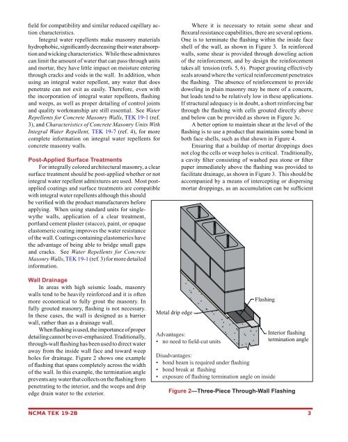
field for compatibility and similar reduced capillary actioncharacteristics.Integral water repellents make masonry materialshydrophobic, significantly decreasing their water absorptionand wicking characteristics. While these admixturescan limit the amount of water that can pass through unitsand mortar, they have little impact on moisture enteringthrough cracks and voids in the wall. In addition, whenusing an integral water repellent, any water that doespenetrate can not exit as easily. Therefore, even withthe incorporation of integral water repellents, flashingand weeps, as well as proper detailing of control jointsand quality workmanship are still essential. See WaterRepellents for Concrete <strong>Masonry</strong> Walls, TEK 19-1 (ref.3), and Characteristics of Concrete <strong>Masonry</strong> Units WithIntegral Water Repellent, TEK 19-7 (ref. 4), for morecomplete information on integral water repellents forconcrete masonry walls.Post-Applied Surface TreatmentsFor integrally colored architectural masonry, a clearsurface treatment should be post-applied whether or notintegral water repellent admixtures are used. Most postappliedcoatings and surface treatments are compatiblewith integral water repellents although this shouldbe verified with the product manufacturers beforeapplying. When using standard units for singlewythewalls, application of a clear treatment,portland cement plaster (stucco), paint, or opaqueelas<strong>to</strong>meric coating improves the water resistanceof the wall. Coatings containing elas<strong>to</strong>merics havethe advantage of being able <strong>to</strong> bridge small gapsand cracks. See Water Repellents for Concrete<strong>Masonry</strong> Walls, TEK 19-1 (ref. 3) for more detailedinformation.Where it is necessary <strong>to</strong> retain some shear andflexural resistance capabilities, there are several options.One is <strong>to</strong> terminate the flashing within the inside faceshell of the wall, as shown in Figure 3. In reinforcedwalls, some shear is provided through doweling actionof the reinforcement, and by design the reinforcementtakes all tension (refs. 5, 6). Proper grouting effectivelyseals around where the vertical reinforcement penetratesthe flashing. The absence of reinforcement <strong>to</strong> providedoweling in plain masonry may be more of a concern,but loads tend <strong>to</strong> be relatively low in these applications.If structural adequacy is in doubt, a short reinforcing barthrough the flashing with cells grouted directly aboveand below can be provided as shown in Figure 3c.A better option <strong>to</strong> maintain shear at the level of theflashing is <strong>to</strong> use a product that maintains some bond inboth face shells, such as that shown in Figure 4.Ensuring that a buildup of mortar droppings doesnot clog the cells or weep holes is critical. Traditionally,a cavity filter consisting of washed pea s<strong>to</strong>ne or filterpaper immediately above the flashing was provided <strong>to</strong>facilitate drainage, as shown in Figure 3. This should beaccompanied by a means of intercepting or dispersingmortar droppings, as an accumulation can be sufficientWall DrainageIn areas with high seismic loads, masonrywalls tend <strong>to</strong> be heavily reinforced and it is oftenmore economical <strong>to</strong> fully grout the masonry. Infully grouted masonry, flashing is not necessary.In these cases, the wall is designed as a barrierwall, rather than as a drainage wall.When flashing is used, the importance of properdetailing cannot be over-emphasized. Traditionally,through-wall flashing has been used <strong>to</strong> direct wateraway from the inside wall face and <strong>to</strong>ward weepholes for drainage. Figure 2 shows one exampleof flashing that spans completely across the widthof the wall. In this example, the termination angleprevents any water that collects on the flashing frompenetrating <strong>to</strong> the interior, and the weeps and dripedge drain water <strong>to</strong> the exterior.Metal drip edgeAdvantages:• no need <strong>to</strong> field-cut unitsFlashingDisadvantages:• bond beam is required under flashing• bond break at flashing• exposure of flashing termination angle on insideInterior flashingtermination angleFigure 2—Three-Piece Through-Wall FlashingNCMA TEK 19-2B 3