to view article - Sutter Masonry
to view article - Sutter Masonry
to view article - Sutter Masonry

You also want an ePaper? Increase the reach of your titles
YUMPU automatically turns print PDFs into web optimized ePapers that Google loves.
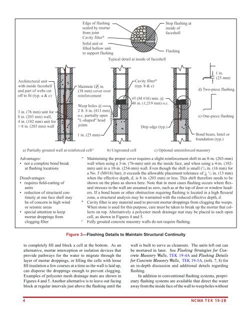
Edge of flashingsealed by mortarfrom jointCavity filter BSolid unit orfilled hollow unit<strong>to</strong> support flashingTypical detail at inside of faceshellS<strong>to</strong>p flashing atinside offaceshellFlashingArchitectural unitwith inside faceshelland part of webs cu<strong>to</strong>ff <strong>to</strong> fit (typ. a & c)3 in. (76 mm) unit for8 in. (203 mm) wall,4 in. (102 mm) unit for> 8 in. (203 mm) wallMaintain 1 1 2 in.(38 mm) cover overreinforcementWeep holes @2 ft. 8 in. (813 mm)o.c. partially open"L-shaped" headjointsCavity filter B(typ. b & c)#5 (M #16) min. @48 in. (1,219 mm) o.c.Drip edge (typ.)1 in.(25 mm)d) Two-piece flashinge) One-piece flashing1 in. (25 mm)Bond beam, lintel orfoundation (typ.)a) Partially grouted wall at reinforced cell Ab) Ungrouted cell c) Optional unreinforced masonryAdvantages:• not a complete bond breakat flashing locationsDisadvantages:• requires field-cutting ofunits• reduction of structural continuityat one face shell maybe of concern in high windor seismic areas• special attention <strong>to</strong> keepmortar droppings fromclogging filterAMaintaining the proper cover requires a slight reinforcement shift in an 8-in. (203-mm)wall when using a 3-in. (76-mm) unit on the inside face, and when using a 4-in. (102-mm) unit in a 10-in. (254-mm) wall. Even though the shift is small ( 5 / 8 in. (16 mm) fora No. 5 (M#16) bar), it exceeds the allowable placement <strong>to</strong>lerance of + 1 / 2 in. (13 mm)when the effective depth, d, is 8 in. (203 mm) or less. This shift therefore needs <strong>to</strong> beshown on the plans as shown here. Note that in most cases flashing occurs where flexuralstresses in the wall are assumed as zero, such as at the <strong>to</strong>p of door or window headers.If a bond beam or other obstruction requiring flashing is located in a high flexuralzone, a structural analysis may be warranted with the reduced effective depth, d.BCavity filter is any material used <strong>to</strong> prevent mortar droppings from clogging the weeps.When s<strong>to</strong>ne is used for this purpose, care must be taken <strong>to</strong> break up the mortar that collectson <strong>to</strong>p. Alternatively a polyester mesh drainage mat may be placed in each opencell, as shown in Figures 4 and 5.CFully grouted concrete masonry walls do not require flashing.Figure 3—Flashing Details <strong>to</strong> Maintain Structural Continuity<strong>to</strong> completely fill and block a cell at the bot<strong>to</strong>m. As analternative, mortar interception or isolation devices thatprovide pathways for the water <strong>to</strong> migrate through thelayer of mortar droppings, or filling the cells with loosefill insulation a few courses at a time as the wall is laid up,can disperse the droppings enough <strong>to</strong> prevent clogging.Examples of polyester mesh drainage mats are shown inFigures 4 and 5. Another alternative is <strong>to</strong> leave out facingblock at regular intervals just above the flashing until thewall is built <strong>to</strong> serve as cleanouts. The units left out canbe mortared in later. See Flashing Strategies for Concrete<strong>Masonry</strong> Walls, TEK 19-4A and Flashing Detailsfor Concrete <strong>Masonry</strong> Walls, TEK 19-5A, (refs. 7, 8) foran in-depth discussion and additional details regardingflashing.In addition <strong>to</strong> conventional flashing systems, proprietaryflashing systems are available that direct the wateraway from the inside face of the wall <strong>to</strong> weep holes without4 NCMA TEK 19-2B