Modular-Instruments-Seminar - National Instruments Germany GmbH
Modular-Instruments-Seminar - National Instruments Germany GmbH
Modular-Instruments-Seminar - National Instruments Germany GmbH

You also want an ePaper? Increase the reach of your titles
YUMPU automatically turns print PDFs into web optimized ePapers that Google loves.
<strong>National</strong> <strong>Instruments</strong><br />
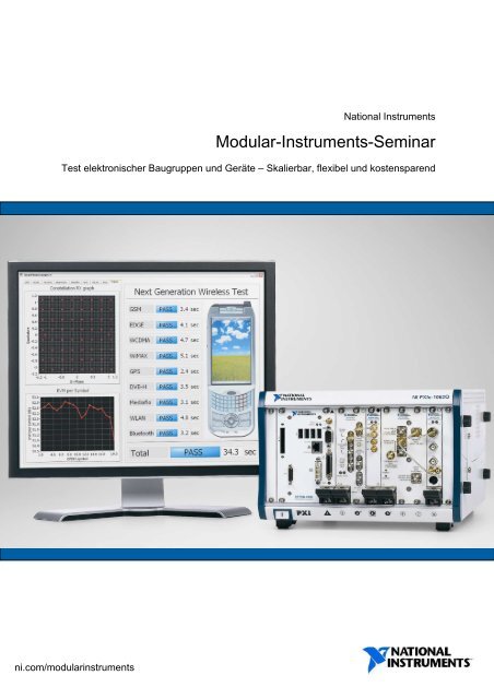
<strong>Modular</strong>-<strong>Instruments</strong>-<strong>Seminar</strong><br />
Test elektronischer Baugruppen und Geräte – Skalierbar, flexibel und kostensparend<br />
ni.com/modularinstruments
Urheberrecht<br />
Copyright © 2009 <strong>National</strong> <strong>Instruments</strong> Corporation. Alle Rechte vorbehalten. Druckfehler, Irrtümer und Änderungen<br />
vorbehalten.<br />
Laut Urheberrecht darf diese Unterlage nicht ohne vorherige Genehmigung von <strong>National</strong> <strong>Instruments</strong> Corporation auf<br />
irgendeine Art elektronisch oder mechanisch – einschließlich Fotokopien, Aufnahmen, Speichern auf einem<br />
Datenwiedergewinnungssystem oder Übersetzung – ganz oder in Teilen vervielfältigt oder übertragen werden.<br />
Warenzeichen<br />
ActiveMath, Analysis Advisor, AutomationView, AutomationWeb, BioBench, BridgeVIEW, CodeBuilder, CodeLink, CompactDAQ,<br />
Compact FieldPoint, CompactRIO, ComponentWorks, Citadel, CVI, CVI logo, DASYLab, DataSocket, DAQAnalyzer, DAQArb,<br />
DAQCard, DAQ Designer, DAQ<strong>Instruments</strong>, DAQMeter, DAQScope, DAQPad, DAQPnP, DAQSourceCode, DAQ-STC, DAQValue,<br />
DAQWare, EagleWare, FieldPoint, Flex ADC, FlexFrame, FlexMotion, HiQ, HiQ-Script, HotPnP, HS488, IMAQ, InsideVIEW,<br />
Instrumentation Studio, Instrumentation Newsletter, InstrumentationWeb, Instrupedia, IVI, LabSuite, LabVIEW, Lookout,<br />
LabWindows/CVI, MANTIS, Measure, Measurement Ready logo, Measurement Suite, Micro GPIB, MIGA, MITE, <strong>National</strong><br />
<strong>Instruments</strong>, <strong>National</strong> <strong>Instruments</strong> logo, natinst.com, ni.com, NAT4882, NAT7210, NAT9914, NI-488, NI-488M, NI-488.2, NI-<br />
488.2M, NI-CAN, NI-DAQ, NI DeveloperSuite, NI-DNET, NI-DSP, NI-FBUS, NI-IMAQ, NI-SHEll, NI-PGIA, NI-VISA, NI-VXI, NIWeek,<br />
PXI, PXI logo, PXI Configurator, RTSI, SCXI, SignalExpress, SmartCode, Spectrum Ware, StillColor, Take Measurements Not<br />
Estimates, TestStand, The Software is the Instrument, The Virtual Instrumentation Company, TIC, T&M Explorer, TNT4882,<br />
TNT4882C, TN4882I, Turbo-488, ValueMotion,VI UserNet, VirtualBench, VMEpc, VXI Integrator, VXIpc, VXIupdate, World Wide<br />
Instrumentation, Your Measurement and Automation Superstore sowie andere Namen, Logos, Icons und Marken, die Produkte<br />
von <strong>National</strong> <strong>Instruments</strong> kennzeichnen, sowie Services und Dienstleistungen hierin sind entweder Warenzeichen oder<br />
registrierte Warenzeichen von <strong>National</strong> <strong>Instruments</strong> und können nicht ohne die schriftliche Genehmigung von <strong>National</strong><br />
<strong>Instruments</strong> verwendet werden.<br />
MATLAB® und Simulink® sind registrierte Warenzeichen von The MathWorks, Inc. Tektronix® und Tek sind registrierte<br />
Warenzeichen von Tektronix, Inc. Andere Produkt- und Firmennamen sind die Warenzeichen oder Handelsbezeichnungen der<br />
jeweiligen Unternehmen.<br />
NIs Internetpräsenz:<br />
E-Mail: support@ni.com<br />
FTP: ftp.ni.com<br />
Web-Adresse: ni.com<br />
Support: ni.com/support<br />
Deutschland: ni.com/germany<br />
info.germany@ni.com<br />
Österreich: ni.com/austria<br />
ni.austria@ni.com<br />
Schweiz: ni.com/switzerland<br />
ni.switzerland@ni.com<br />
Kontaktaufnahme mit NI per Telefon, Fax oder Post:<br />
<strong>National</strong> <strong>Instruments</strong> <strong>Germany</strong> <strong>GmbH</strong><br />
Konrad-Celtis-Str. 79<br />
81369 München<br />
Tel.: +49 89 7413130<br />
Fax: +49 89 7146035<br />
<strong>National</strong> <strong>Instruments</strong> Ges.m.b.H.<br />
Plainbachstr. 12<br />
A-5101 Salzburg-Bergheim<br />
Tel.: +43 662 457990-0<br />
Fax: +43 662 457990-19<br />
<strong>National</strong> <strong>Instruments</strong> Switzerland Corp.<br />
Austin, Zweigniederlassung Ennetbaden<br />
Sonnenbergstr. 53<br />
CH-5408 Ennetbaden<br />
Tel.: +41 56 2005151<br />
Fax: +41 56 2005155<br />
<strong>National</strong> <strong>Instruments</strong> Firmenhauptsitz<br />
11500 N Mopac Expwy, Austin, TX 78759-3504, USA – Tel.: +1 512 683-0100<br />
1<br />
<strong>National</strong> <strong>Instruments</strong> – CER Region <strong>Modular</strong>-<strong>Instruments</strong>-<strong>Seminar</strong>
Ihr <strong>National</strong> <strong>Instruments</strong> Team in Deutschland, Österreich und der Schweiz<br />
Hauptniederlassung Deutschland<br />
Konrad-Celtis-Str. 79<br />
D-81369 München Rolf Oechsler (PLZ 66, 69, 74-79)<br />
Tel.: +49 89 7413130 mobil: +49 (0)175 2625160<br />
Fax: +49 89 7146035 rolf.oechsler@ni.com<br />
info.germany@ni.com<br />
ni.com/germany Benjamin Michel (PLZ 66, 69, 74-79)<br />
mobil: +49 (0)151 15134872<br />
Vertriebsleiter NI <strong>Germany</strong> benjamin.michel@ni.com<br />
Georg Plaßwilm<br />
mobil: +49 (0)171 6526470 Philippe Götz (PLZ 70-73)<br />
georg.plasswilm@ni.com mobil: +49 (0)175 2231839<br />
philippe.goetz@ni.com<br />
Vertriebsgebiet Nord/Ost<br />
Vertriebsleiter: Thomas Rönpage Peter Griese (PLZ 86-89)<br />
mobil: +49 (0)171 4720866 mobil: +49 (0)171 7509127<br />
thomas.roenpage@ni.com peter.griese@ni.com<br />
Bernhard Raabe (PLZ 19-29 und 38) Büro Stuttgart<br />
mobil: +49 (0)171 7746806 Tel.: +49 711 72876200<br />
bernhard.raabe@ni.com Fax: +49 711 72876230<br />
Jörgen Etter (PLZ 01-05, 08-18) Hauptniederlassung Österreich<br />
mobil: +49 (0) 170 4542170 Plainbachstraße 12<br />
joergen.etter@ni.com A-5101 Salzburg-Bergheim<br />
Tel.: +43 662 457990-0<br />
Udo Henkelmann (PLZ 06-07, 30-32, 34, 37, 39, 98-99) Fax: +43 662 457990-19<br />
mobil: +49 (0)175 2236142 ni.austria@ni.com<br />
udo.henkelmann@ni.com ni.com/austria<br />
Vertriebsgebiet West Vertriebsgebiet NI Austria<br />
Vertriebsleiter: Markus Heinze Vertriebsleiter: Günther Stefan (PLZ 4500-6999)<br />
mobil: +49 (0)151 12107312 mobil: +43 (0)676 845391200<br />
marcus.heinze@ni.com guenther.stefan@ni.com<br />
Carsten Sprung (PLZ 35, 41, 50-54, 56, 57) Paul Schmitzberger (PLZ 1000-4499, 7000-7299)<br />
mobil: +49 (0)170 5616179 mobil: +49 (0) 676845391300<br />
carsten.sprung@ni.com paul.schmitzberger@ni.com<br />
Rolf Kall (PLZ 35, 41, 50-54, 56-57) Helmut Wurm (PLZ 7300-9999)<br />
mobil: +49 (0)175 7247971 mobil: +43 (0)676 845391400<br />
rolf.kall@ni.com helmut.wurm@ni.com<br />
Daniel Hermyt (PLZ 33, 35, 40-54. 56-59)) Evrem Yarkin (PLZ 6700-6900)<br />
mobil: +49 (0) 160 9358025 mobil: +41 (0)76 3145132<br />
daniel.hermyt@ni.com evrem.yarkin@ni.com<br />
Vertriebsgebiet Südost Hauptniederlassung Schweiz/Liechtenstein<br />
Vertriebsleiter: Markus Kötterl CH-5408 Ennetbaden<br />
mobil: +49 (0)171 9768334 Tel.: +41 56 2005151<br />
markus.koetterl@ni.com Fax: +41 56 2005155<br />
Sonnenbergstraße 53 ni.switzerland@ni.com<br />
ni.com/switzerland<br />
Christian Spiss (PLZ 80-83)<br />
mobil: +49 (0)175 9358025<br />
christian.spiss@ni.com Vertriebsleiter NI Switzerland<br />
Geschäftsführer: Christian Moser<br />
Stefan Henke (PLZ 84-85, 93-94) christian.moser@ni.com<br />
mobil: +49 (0)171 3837854<br />
stefan.henke@ni.com Joël Clerc (PLZ 1000-2999)<br />
mobil: +41 (0)76 3145137<br />
André Saller (PLZ 84-85, 93-94) joel.clerc@ni.com<br />
mobil: +49 (0)170 8575372<br />
andre.saller@ni.com Luca Pretto (PLZ 3000-6999)<br />
mobil: +41 (0)76 3145134<br />
Nikolai Rösch (PLZ 90-92,95,96) luca.pretto@ni.com<br />
mobil: +49 (0) 170 9218228<br />
nikolai.roesch@ni.com Oliver Bruder (8000-8699, 9000-9399, 9999)<br />
mobil: +41 (0)76 3145130<br />
Vertriebsgebiet Südwest oliver.bruder@ni.com<br />
Vertriebsleiter: Christian Gröbmüller<br />
mobil: +49 (0)175 2232584 Evrem Yarkin (PLZ 5000-5900, 7000-7900, 8700-8900, 9400-9499)<br />
christian.groebmueller@ni.com mobil: +41 (0)76 3145132<br />
evrem.yarkin@ni.com<br />
Saso Veskovski (PLZ 36, 55, 60-65)<br />
mobil: +49 (0)171 7650497<br />
saso.veskovski@ni.com<br />
2<br />
<strong>National</strong> <strong>Instruments</strong> – CER Region <strong>Modular</strong>-<strong>Instruments</strong>-<strong>Seminar</strong>
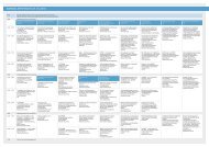
Index<br />
Section 1 5<br />
Section 2 10<br />
Section 3 – The PXI Plattform 24<br />
Section 4 – Designing PXI Systems for Semiconductor Characterization 37<br />
Exampel 1: Transistor Testing 39<br />
Example 2: Voltage Reference Testing 43<br />
Example 3: DC Parametric Measurements 48<br />
Types of Semiconductor Tests<br />
Example 1: Memory Test 58<br />
Example 2: Serializer / Deserializer (SerDes) 65<br />
Example 3: Analog to Digital Converters (ADCs) 71<br />
Example 4: Digital to Analog Converter (DAC) 78<br />
Example 5: AC Parametric Testing 83<br />
Example 6: Amplifier /Attenuator (LNA) 87<br />
Example 7: Direct Quadrature Modulator 91<br />
Section 5 – Unique Implementations for System Test 102<br />
3<br />
<strong>National</strong> <strong>Instruments</strong> – CER Region <strong>Modular</strong>-<strong>Instruments</strong>-<strong>Seminar</strong>
4<br />
<strong>National</strong> <strong>Instruments</strong> – CER Region <strong>Modular</strong>-<strong>Instruments</strong>-<strong>Seminar</strong>
Before we we get get into what tools and and techniques techniques NI can offer, let’s let’s first first address address some challenges that most<br />
everyone in in the industry industry is is facing. facing. Since Since our our audience audience today today may may contain a a diverse diverse crowd crowd from very<br />
different areas areas of of the the industry, it’s important to to realize that we continue continue to see see some some pervasive<br />
pervasive<br />
challenges and needs to which NI can offer unique sol solutions, utions, and this applies to applications from design<br />
and validation, all the way through manufacturing and production test.<br />
<strong>National</strong> <strong>Instruments</strong> – CER Region<br />
5<br />
<strong>Modular</strong>- -<strong>Instruments</strong>-<strong>Seminar</strong>
The single single largest largest trend that we continue to to see see is is that the cost of of test test is is simply simply too too high. high. Although the<br />
cost of manufacturing semiconductor components and ICs ICs has been driven down by technological<br />
advancements (most notably in manufacturing and fabrication), the cost of of test equipment equipment and test<br />
test<br />
systems has remained relatively constant, so as a percentage of total cost, the cost of test is<br />
skyrocketing. This This trend is affecting everyone everyone from from design to manufacturing manufacturing as teams teams are having to work<br />
work<br />
together to solve this complex issue.<br />
There are are actually actually quite quite a a few few new new techniques techniques that that people are using using such as Design for Test (DFT) (DFT) and<br />
and<br />
Design ign for for Manufacturability Manufacturability which are helping to reduce costs costs through innovations innovations in in design. Today,<br />
Today,<br />
we’ll be focusing more more on on the test systems themselves (as opposed to techniques techniques used throughout the<br />
design cycle) in order to find solutions to this pervasive problem from a test-focused focused approach.<br />
I’m sure most of of you you have have already already heard heard of PXI PXI (PCI (PCI Extensions for for Instrumentation) Instrumentation) as NI’s NI’s primary<br />
primary<br />
platform for test equipment, and indeed PXI is is going going to to hold a lot of answers to reducing test costs in<br />
terms of instruments ruments as as well well as ownership costs, flexibility, future development and and reuse. Lowering Lowering the<br />
the<br />
cost of test will be a theme throughout today’s presentation.<br />
<strong>National</strong> <strong>Instruments</strong> – CER Region 6<br />
<strong>Modular</strong>- -<strong>Instruments</strong>-<strong>Seminar</strong>
Another trend trend that is gaining more attention is the increase in in global global design and and manufacturing. There Th<br />
are many complex issues surrounding this topic. From a product development standpoint standpoint it is is important<br />
important<br />
for design design engineers, test test engineers, engineers, and managers managers to be able to to support support their product designs and test<br />
systems around the world. If you’re designing a device that will be manufactured on the other side of the<br />
world, you need to understand how the test systems are used so so that that you you understand how it it impacts impacts the<br />
yield rate and quality of your device. This reinforces the need to more closely link link design and an<br />
test<br />
systems.<br />
NI provides worldwide support and and services services to meet the the needs of our our customers customers with with direct operation in<br />
in<br />
more than 40 countries. In addition to local support as well as online resources,<br />
NI has developed global relationships with many industry partners that give our customers a complete<br />
spectrum of solutions.<br />
<strong>National</strong> <strong>Instruments</strong> – CER Region 7<br />
<strong>Modular</strong>- -<strong>Instruments</strong>-<strong>Seminar</strong>
Another big big trend that is accompanying the increasing costs and globalization in in the the semiconductor<br />
industry is is the the movement movement toward combined architectures such as as system on on a a chip and and system in a<br />
package designs. designs. The The idea idea is that the more functionality that can can be be integrated integrated into into single single chip chip or<br />
or<br />
package, the cheaper and more efficient it can be. The end end result result is is that that the the complexity complexity of of a a single<br />
single<br />
component or device is increasing – and this is trend really applies to consumer electronics all the way<br />
down to wafer-level design.<br />
At the highest level, the easiest example is a cell-phone, cell phone, which now houses video, audio, rf signals for<br />
both phone conversations as well as internet, as well as digita digital l communication, memory, blue-tooth, blue<br />
infrared and the list goes on. Obviously, the complexity of testing a cell-phone cell phone is drastically higher than<br />
testing single-purpose devices.<br />
As these multi-purpose purpose devices devices have become increasingly prevalent, semiconductor semiconducto designs have begun<br />
incorporating multiple multiple integrated integrated circuit circuit components components onto a a single die (or chip) whereas whereas before before they<br />
would’ve been been distinct units that could’ve been tested separately separately and and assembled onto a single PCB. PCB. Now<br />
Now<br />
that they are part of the same chip, access to each each section of of the the system (on the the chip) is is limited limited and the<br />
trend has been to to move move toward toward functional functional testing of of the the entire chip as opposed opposed to to individual component<br />
component<br />
test. This poses new problems for traditional test approaches.<br />
<strong>National</strong> <strong>Instruments</strong> – CER Region 8<br />
<strong>Modular</strong>- -<strong>Instruments</strong>-<strong>Seminar</strong>
For both of the cases described above, we’ll see how PXI is going to provide some very unique benefits<br />
over existing solutions due to its extreme diversity of instrumentation and the way in which the<br />
instruments can be integrated together.<br />
9<br />
<strong>National</strong> <strong>Instruments</strong> – CER Region <strong>Modular</strong>-<strong>Instruments</strong>-<strong>Seminar</strong>
Now, before we go into depth h on the types of tests that can be be performed, performed, the hardware, and and the<br />
implementation of low-cost cost systems, let’s also quickly quickly introduce NI as a a company company so that everyone everyone is<br />
is<br />
familiar with our vision.<br />
NI continues it’s track record of delivering pioneering engi engineering neering products to deliver productivity to<br />
engineers and scientists across the world.<br />
For those of of you you who who are not familiar with NI, we are a company with with over over 25 25 years years in in the measurement<br />
and automation industry. We are an engineering company committed tto<br />
o providing the most productive<br />
tools to engineers engineers all over the world. Our heavy heavy investment investment in in R&D allows NI to provide provide a a steady stream<br />
stream<br />
of cutting edge products products to fill the ever changing and demanding demanding needs needs that that engineers engineers face today. As you<br />
can see from our r financial results, NI has been able to to achieve achieve a long term term track record record of of growth, and<br />
and<br />
we have done this thru our unique approach to solving engineers problems - this approach is called<br />
Virtual Instrumentation.<br />
<strong>National</strong> <strong>Instruments</strong> – CER Region 10<br />
<strong>Modular</strong>-<strong>Instruments</strong>-<strong>Seminar</strong>
Since it was founded in 1976, <strong>National</strong> <strong>Instruments</strong> has achieved constant growth. NI strives to provide<br />
innovative, computer-based based products for customers to develop higher higher-quality quality systems and products<br />
within a shorter timeframe, in in order to improve our our everyday life. To achieve this goal, <strong>National</strong> Natio<br />
Instrument invests invests a a large large part part of of its total total revenue in R&D. Therefore, Therefore, NI NI can provide provide the the newest<br />
newest<br />
technology trends trends for industrial applications, meeting the constantly growing growing needs needs of its its customers.<br />
<strong>National</strong> <strong>Instruments</strong> has more than 5,000 employees who work in five development centers and over<br />
40 branch offices around around the world as well as in the two production sites in Europe and the USA.<br />
<strong>National</strong> <strong>Instruments</strong> sells its its products products to a broad base base of more than 25,000 25,000 customers in over over 90<br />
90<br />
countries. Customers mers work work in all all areas areas of of industry and research and use use the range range of more more than than 1,500<br />
1,500<br />
products for an extensive variety of applications.<br />
With full full schedules, schedules, limited technical resources or other bottlenecks you might might want technical technical or<br />
personal consultation or services in the area of system integration. In that case case <strong>National</strong> <strong>National</strong> <strong>Instruments</strong>’<br />
customers benefit from from the Alliance Partner Program, an international network network of of experts, experts, engineering<br />
engineering<br />
consultants and system integrators who are happy to contribute their expertise. exp<br />
<strong>National</strong> <strong>Instruments</strong> – CER Region 11<br />
<strong>Modular</strong>- -<strong>Instruments</strong>-<strong>Seminar</strong>
We want our employees to feel good – the fact that NI has been named one of the 100 best companies<br />
to work for in America for the past ten years by FORTUNE magazine, proves that we are successful in<br />
providing a great place to work. NI <strong>Germany</strong> was voted among the best 50 places to work for in <strong>Germany</strong><br />
in 2004, 2005, 2008 and 2009.<br />
12<br />
<strong>National</strong> <strong>Instruments</strong> – CER Region <strong>Modular</strong>-<strong>Instruments</strong>-<strong>Seminar</strong>
<strong>National</strong> <strong>Instruments</strong> transforms the way engineers engineers and scientists scientists around around the the world world design, prototype,<br />
prototype,<br />
and deploy systems for test, control, and embedded design applicat applications. ions. Using NI open graphical<br />
programming software and modular hardware, customers at more more than 25,000 companies annually<br />
simplify development, development, increase productivity, and dramatically dramatically reduce reduce time to market. From From testing testing next-<br />
next<br />
generation gaming systems to creating breakthrough medical devices, NI customers continuously<br />
develop innovative technologies that impact millions of people.<br />
Over the last last 20 20 years LabVIEW has earned a strong reputation as the software tool for creating<br />
measurement solutions. LabVIEW users have an advantage of traditional text based programmers by<br />
reducing development time, and taking advantage of functionality that is pre pre-built built for test and control<br />
applications. This This enables users to reduce development time by by up to 40% 40% and and easily easily creat create creat complex<br />
data acquisition and and control applications which previously required extensive knowledge of software<br />
software<br />
design.<br />
<strong>National</strong> <strong>Instruments</strong> – CER Region 13<br />
<strong>Modular</strong>- -<strong>Instruments</strong>-<strong>Seminar</strong>
<strong>National</strong> <strong>Instruments</strong> is is fortunate to assist more more than than 25,000 different companies each year in selecting<br />
the optimal solution for their test and measurement needs. NI continuously monitors the latest latest trends<br />
trends<br />
and challenges challenges in in the industry through working with more than 90% 90% of the Fortune 500 500 manufacturing<br />
companies.<br />
<strong>National</strong> <strong>Instruments</strong> – CER Region 14<br />
<strong>Modular</strong>- -<strong>Instruments</strong>-<strong>Seminar</strong>
<strong>National</strong> <strong>Instruments</strong> – CER Region 15<br />
<strong>Modular</strong>- -<strong>Instruments</strong>-<strong>Seminar</strong>
That platform is Graphical System Design. Graphical System Design provides a strong development<br />
platform for at least the next 30 years – empowering engineers and scientists to accelerate their<br />
development process – whether it be an industrial machine or complex test system – with an open,<br />
intuitive platform. From design – including algorithm, filter, and simulation design – to prototype with<br />
tightly integrated integrated hardware and software with with I/O I/O all the way to to deploy deploy to to the factory floor or or a final<br />
embedded product.<br />
<strong>National</strong> <strong>Instruments</strong> – CER Region 16<br />
<strong>Modular</strong>- -<strong>Instruments</strong>-<strong>Seminar</strong>
Virtual Instrumentation, at the most basic level, is the cconcept<br />
oncept of having software define the<br />
functionality of hardware. In this manner, measurement, analysis, and presentation presentation are are not not propriety propriety or<br />
or<br />
fixed, but but open and and customizable. This is reflected in the model model above, above, where the three main steps steps are<br />
Acquire, Analyze, and Present – and where the analysis and presentation presentation are user user-defined user and flexible.<br />
This software-defined defined flexibility is one of the key benefits of virtual instrumentation.<br />
instrumentation.<br />
Now, for virtual instrumentation to be successful, a strong software archite architecture cture and easy easy-to-use tools<br />
are essential.<br />
<strong>National</strong> <strong>Instruments</strong> – CER Region 17<br />
<strong>Modular</strong>- -<strong>Instruments</strong>-<strong>Seminar</strong>
And indeed, all of the challenges that we’ve described require a test platform platform that can can keep pace with<br />
new innovations and changes. The platform must include rapid rapid test development tools tools adaptable<br />
enough to be used throughout the product development flow. flow. The need to to get get products products to volume<br />
quickly and manufacture them efficiently requires high-throughput high throughput test. To test the complex<br />
multifunction products products that that consumers demand requires precise, precise, synchronized measure measurement<br />
measure<br />
capabilities. And as you incorporate innovations to differentiate your your products, your test system must<br />
quickly adapt to test the new features.<br />
Virtual instrumentation instrumentation is an innovative solution to to these challenges. Virtual instrumentation combines<br />
rapid d development software and modular, flexible hardware to create user user-defined defined test systems. Virtual<br />
instrumentation delivers:<br />
• Intuitive software tools for rapid test development<br />
• Fast, precise modular I/O based on innovative commercial technologies<br />
• A PC-based ased platform with integrated synchronization for high accuracy accuracy and throughput<br />
<strong>National</strong> <strong>Instruments</strong> – CER Region 18<br />
<strong>Modular</strong>- -<strong>Instruments</strong>-<strong>Seminar</strong>
What is NI LabVIEW? LabVIEW is a highly highly productive graphical development development environment with the<br />
performance and flexibility of a programming language, as well as high-level high functionality ctionality and<br />
configuration utilities designed specifically for measurement and automation applications.<br />
In general-purpose purpose programming programming languages, the the code is as much of a concern as as the the application. application. You<br />
You<br />
must pay close attention to the syntax (commas, periods, semicolons, square brackets, curly brackets,<br />
round brackets, and so on). In contrast, with with LabVIEW LabVIEW you use icons to represent represent functions, and and you you wire<br />
them together to to determine the flow flow of data through your your program, similar similar to to creating flowcharts. It It has<br />
all the breadth and depth of a general-purpose general purpose programming language, but it is easy to use, increasing<br />
your productivity by decreasing the time required to develop your applications.<br />
You can easily divide measurement and automation application into tthree<br />
hree main parts: acquisition,<br />
analysis, and and presentation of data. LabVIEW provides a seamless way way to acquire your data, perform<br />
necessary analysis analysis on that data, and present the information in a chosen format. Throughout the<br />
seminar, we touch upon each of these three components of a measurement and automation application.<br />
Each program in LabVIEW is called called a virtual virtual instrument, or or VI. The VI VI serves as the primary primary building block<br />
block<br />
of a LabVIEW application, and and you you can can use use it it to to modularize modularize your code for for efficient design, clear and<br />
concise documentation, and simplified maintenance.<br />
<strong>National</strong> <strong>Instruments</strong> – CER Region 19<br />
<strong>Modular</strong>- -<strong>Instruments</strong>-<strong>Seminar</strong>
Just as measurement hardware has evolved over the years to become more more powerful powerful and easier to use,<br />
so has software. Express technology in LabVIEW is designed specifically for the the purpose pur<br />
of helping<br />
engineers be be more more productive, without removing functionality. functionality. Express VIs VIs are are available in in LabVIEW 7<br />
Express and later to streamline your application development. There There are over over 40 40 Express Express VIs included included in<br />
LabVIEW that enable you to create ccomplete<br />
omplete measurement programs in minutes. These VIs were created<br />
for the the most most frequently frequently built built applications applications with your your productivity productivity and efficiency needs needs in mind. mind. The The power<br />
you have with Express VIs is found in the property pages for for each each that you you can individ<br />
individually customize<br />
simply by double-clicking clicking them. This will significantly reduce the number of objects objects on on your your Block<br />
Block<br />
Diagram and the time needed to add additional functionality. Additionally, Additionally, hundreds hundreds of of Standard VIs are<br />
are<br />
available from the All Functions Pale Palette, tte, making LabVIEW a complete programming language.<br />
Express VIs for for <strong>Modular</strong> <strong>Instruments</strong> allow you you to quickly quickly configure common common configuration parameters<br />
such as sample rate, triggering, and more. In addition, these Express VIs allow you to acquire or or generate genera<br />
signals directly directly from from the the interactive interactive configuration panel, panel, so so you you can can rapidly rapidly develop your measurement<br />
measurement<br />
tasks. The The Instrument Instrument I/O I/O Assistant Assistant is designed to make make direct direct communication with your traditional<br />
instruments more productive. With the new DAQ Assistant, you can quickly configure your data<br />
acquisition tasks tasks to to include include custom custom timing, timing, scaling, scaling, triggering, and more with no no programming. Tasks Tasks that<br />
previously took from 5–10 10 standard VIs with manually-wired manually wired parameters now take only a single,<br />
interactive VI that can automatically generate low-level low level data acquisition LabVIEW code.<br />
<strong>National</strong> <strong>Instruments</strong> – CER Region 20<br />
<strong>Modular</strong>- -<strong>Instruments</strong>-<strong>Seminar</strong>
LabVIEW is ideally suited for acquiring, analyzing, and presenting data regardless of whether that data is<br />
acquired from a traditional instrument or a data acquisition board. LabVIEW provides tools for<br />
integrating a wide range of instrument control buses, including PCI, PXI, GPIB, USB, serial, Ethernet, and<br />
VXI. After acquiring the raw data, LabVIEW has the tools for parsing, analyzing, and presenting the data.<br />
With the new Instrument I/O Assistant, you can communicate directly with your GPIB, Ethernet, USB,<br />
serial, PXI, and VXI instruments. You can use this interactive wizard to prototype your instrument control<br />
system, take quick measurements, and even develop simple instrument drivers.<br />
In addition to providing direct I/O support for just about any instrument that supports a programmatic<br />
interface, <strong>National</strong> <strong>Instruments</strong> has over 1,400 LabVIEW instrument drivers. An instrument driver is a<br />
LabVIEW VI library that contains high-level VIs that allow you to control a specific instrument or family of<br />
instruments.<br />
21<br />
<strong>National</strong> <strong>Instruments</strong> – CER Region <strong>Modular</strong>-<strong>Instruments</strong>-<strong>Seminar</strong>
Although we’ve we’ve seen many users see see dramatic dramatic benefits benefits from moving moving to to LabVIEW, we also understand<br />
understand<br />
that many companies have already heavily invested in text text-based based languages in regards reg to both existing<br />
code and programmers.<br />
LabWindows /CVI /CVI is based on on open open ANSI C standards, standards, thus shielding you you from the proliferation of<br />
software and network technology. One of the industry industry-leading leading test packages, LabWindows/CVI has<br />
continued to innovate throughout its more than 15 year histor history. y. The latest version, 7.0, introduced a<br />
new integrated workspace environment optimized for large project development, development, new user interface<br />
interface<br />
capabilities, and new Express technology-driven technology measurement assistants.<br />
<strong>National</strong> <strong>Instruments</strong> – CER Region 22<br />
<strong>Modular</strong>- -<strong>Instruments</strong>-<strong>Seminar</strong>
We’ve seen virtual instrumentation help engineers and scientists from all disciplines and all ages focus<br />
on their application, not our software. Initially, the concept of virtual instrumentation instrumentation was was targeted at<br />
automated test, but but has has since since expanded expanded rapidly rapidly in the fields of of design design and control. Toda Today, we’ll be<br />
discussing recent advancements virtual instrumentation for automated test.<br />
<strong>National</strong> <strong>Instruments</strong> – CER Region 23<br />
<strong>Modular</strong>- -<strong>Instruments</strong>-<strong>Seminar</strong>
Now that we’re familiar with the software strategy strategy that NI provides, provides, let’s let’s quickly quickly take a a look look at how the<br />
the<br />
PXI platform fits into this architecture before we begin designing des systems.<br />
<strong>National</strong> <strong>Instruments</strong> – CER Region 24<br />
<strong>Modular</strong>- -<strong>Instruments</strong>-<strong>Seminar</strong>
At the heart heart of of our our message message of of virtual instrumentation, is the fact that that software software is is essential essential to to the<br />
the<br />
success of any any automated test system. Furthermore, the software software can’t just just be an afterthought in a a test<br />
strategy, but it should be the backbone of the system.<br />
A well-integrated integrated software strategy strategy must take into into consideration every layer of of software, software, including<br />
measurement and control control services, services, application application development environments, and system management<br />
software. The integrated software plat platform form from <strong>National</strong> <strong>Instruments</strong> provides a modular suite of<br />
software tools optimized for test integration integration with design and enterprise tools. The flexible software<br />
platform also allows you you to choose the software development development environment that that best fits the needs need of<br />
your application application and developer developer by by offering offering three three approaches approaches to test software development: development: Graphical,<br />
ANSI C, or .NET.<br />
<strong>National</strong> <strong>Instruments</strong> – CER Region 25<br />
<strong>Modular</strong>- -<strong>Instruments</strong>-<strong>Seminar</strong>
PXI (PCI eXtensions for Instrumentation) is a rugged PC PC-based based platform for measurement and<br />
automation systems. PXI combines PCI el electrical-bus bus features with the rugged, modular, Eurocard<br />
mechanical-packaging packaging of CompactPCI, then adds adds specialized synchronization synchronization buses and key key software<br />
software<br />
features. This makes it both a high-performance high<br />
and low-cost cost deployment platform for measurement<br />
and automation utomation systems. These These systems serve serve applications such as manufacturing test, test, military and<br />
aerospace, machine monitoring, automotive, and industrial test.<br />
Developed in in 1997 and and launched launched in in 1998, 1998, PXI was was introduced introduced as as an an open open industry standard to meet the<br />
the<br />
increasing demands demands of of complex instrumentation systems. Today, PXI is governed by the the PXI PXI Systems<br />
Systems<br />
Alliance (PXISA), (PXISA), a group of more than than 65 65 companies chartered to to promote the PXI standard, standard, ensure<br />
ensure<br />
interoperability, and maintain the PXI specification. For more information on the PXISA, including the PXI<br />
specification, refer to the PXISA Web site at www.pxisa.org.<br />
The chassis chassis provides provides the the rugged and modular packaging for the system. system. Chassis Chassis generally range in size<br />
size<br />
from four slots to 18 slots and are also available with special features such as DC power supplies and<br />
integrated signal conditioning. The chassis contains the high-performance high performance PXI backplane, which includes<br />
the PCI bus bus and timing timing and and triggering buses. These timing and and triggering buses enable users users to to develop<br />
systems for applications requiring precise synchronization. For more more information information on the the functionality of<br />
the PXI timing timing and triggering buses, buses, refer to to the the PXI Hardware Hardware Specification Specification at at www.pxisa.org/specs.htm.<br />
www.pxisa.org/specs.htm.<br />
<strong>National</strong> <strong>Instruments</strong> – CER Region 26<br />
<strong>Modular</strong>- -<strong>Instruments</strong>-<strong>Seminar</strong>
As defined by the PXI Hardware Specification, all PXI chassis contain a system controller slot located in<br />
the leftmost slot of the chassis (slot 1). Controller options include remote control from a standard<br />
desktop PC or a high-performance embedded control with either a Microsoft operating system (such as<br />
Windows 2000/XP) or a Real-Time operating system (such as LabVIEW Real-Time).<br />
27<br />
<strong>National</strong> <strong>Instruments</strong> – CER Region <strong>Modular</strong>-<strong>Instruments</strong>-<strong>Seminar</strong>
PXI is is a a platform platform with with a breadth breadth of of functionality, functionality, including modules for analog and digital I/O, I/O, high-speed high<br />
instrumentation, vision, motion, and numerous bus interfaces. Over 1,000 PXI modules are available<br />
from the 70+ members of the PXISA. On average, <strong>National</strong> <strong>Instruments</strong> release a new new PXI PXI product product each<br />
each<br />
week.<br />
<strong>National</strong> <strong>Instruments</strong> – CER Region 28<br />
<strong>Modular</strong>- -<strong>Instruments</strong>-<strong>Seminar</strong>
For a modular instrumentation architecture such as PXI, a key requirement is to have have a bus that is<br />
is<br />
capable apable of keeping up up with with the the throughput throughput needs needs of all all modules. PXI is based on two main underlying<br />
underlying<br />
technologies – PCI and PCI express. Both of these busses busses offer higher higher bandwidth bandwidth and lower lower latency latency than<br />
any other standard instrumentation bus.<br />
Moving forward, , NI will continue to support and innovate on the PXI platform –<br />
as well as PXI modules.<br />
both on PXIe modules<br />
<strong>National</strong> <strong>Instruments</strong> – CER Region 29<br />
<strong>Modular</strong>- -<strong>Instruments</strong>-<strong>Seminar</strong>
Two main factors that generally characterize the performance of a bus bus are are latency latency and bandwidth.<br />
bandwidth.<br />
Latency is a measure of how long it takes ffor<br />
or a device to reply to a request. Bandwidth is a measure of<br />
how much data can be transferred across the bus in a given amount of time. It is the combination of<br />
latency and and bandwidth bandwidth which will affect affect the speed of of your your measurement system. This graph shows the<br />
performance tradeoffs of of using the system system bus bus or or a peripheral bus. The The best latency and bandwidth<br />
performance occurs on system busses such as PCI/PXI and PCIe/PXIe.<br />
<strong>National</strong> <strong>Instruments</strong> – CER Region 30<br />
<strong>Modular</strong>- -<strong>Instruments</strong>-<strong>Seminar</strong>
Another important important note note is that with the introduction of PCI PCI Express, engineers engineers now h<br />
have a bus option<br />
that provides provides each each device device with with its its own own dedicated data pipeline. Thus, Thus, as as multiple multiple PCI Express devices are<br />
are<br />
added to to a system, the total bus throughput scales linearly. This This is is especially especially noteworthy for applications<br />
such as RF record & playback ack or high high-channel channel count continuous audio acquisition where multiple devices<br />
need a high-throughput throughput communication line to the host PC.<br />
NI offers a wide range of of PXI PXI chassis and PXI instrumentation as well well as PXIe/PXI hybrid chassis and and PXIe<br />
PXIe<br />
instrumentation.<br />
<strong>National</strong> <strong>Instruments</strong> – CER Region 31<br />
<strong>Modular</strong>- -<strong>Instruments</strong>-<strong>Seminar</strong>
Yet another key key advantage advantage of the PXI platform platform is is the timing timing and and synchronization that it offers. offers. Shown<br />
Shown<br />
above is the routing diagram for triggers in an 8-slot 8 slot PXIe hybrid chassis. You can see that alone, the PXI<br />
specification calls for a 10 MHz clock routed to all modules as well as a 8 TTL trigger lines and a star<br />
trigger line that offers matched trace lengths. To To add to to that, the PXIe spec provides a 100 100 MHz<br />
differential clock clock for for lower lower noise noise and higher higher rates rates as as well as a a synchronization signal signal for t tthat<br />
clock.<br />
Finally, the PXIe specification calls for three sets of differential star triggers.<br />
• PXIe timing and synchronization offers the following benefits:<br />
• higher frequencies on star trigger lines – now up to 3 GHz<br />
• Synchronize mixed modules – SYNC 100 synchs 10 and 100 MHz clocks<br />
• Synchronize mixed chassis – use CLK 10 and then sync 100<br />
• Synch PXI Express chassis – use sync 100 which sends out a low freq pulse that aligns the 10 and<br />
100 Mhz clocks within a chassis – use across multiple chassis.<br />
<strong>National</strong> <strong>Instruments</strong> – CER Region 32<br />
<strong>Modular</strong>- -<strong>Instruments</strong>-<strong>Seminar</strong>
As a result lt of the platform advantages advantages of of PXI, PXI, it it has has become become the fastest growing platform/standard platform/standard in in the<br />
the<br />
test industry. Frost and Sullivan has predicted that it it continue continue to grow grow at at its current pace pace of 23% 23% CAGR<br />
through 2011.<br />
<strong>National</strong> <strong>Instruments</strong> – CER Region 33<br />
<strong>Modular</strong>-<strong>Instruments</strong>-<strong>Seminar</strong>
One of the reasons the platform has see such success and such a high growth rate of available modules<br />
and revenue is industry-wide wide participation in in the PXI Systems Systems Alliance, Alliance, the governing governing body that manages<br />
the PXI specification. specification. Today there are over over 65 companies in the PXI PXI Systems Systems Alliance, Alliance, including LeCroy,<br />
Teradyne, Virginia Virginia Panel, Panel, JTAG, JTAG, and and <strong>National</strong> <strong>Instruments</strong>, as well well as other PXI vendors vendors and system<br />
integrators. Of Of course, course, this is only a partial list of members, and and a complete complete list list can be found at<br />
www.pxisa.org.<br />
<strong>National</strong> <strong>Instruments</strong> – CER Region 34<br />
<strong>Modular</strong>- -<strong>Instruments</strong>-<strong>Seminar</strong>
Here are some of the modules we’ll see throughout today’s examples examples and and demonstrations - you can see<br />
how typical components of semiconductor test systems exist in the PXI form form-factor. factor. We’ll focus on how<br />
to combine these elements to accomplish certain tasks, and the benefits of the PXI architecture in each<br />
of these applications.<br />
<strong>National</strong> <strong>Instruments</strong> – CER Region 35<br />
<strong>Modular</strong>-<strong>Instruments</strong>-<strong>Seminar</strong>
Another way way to visualize the diversity of these modules is is on on this graph of Resolution vs. Frequency. You<br />
can see here that in terms of analog instrumentation instrumentation there there are are categories for for high-resolution high DC,<br />
precision audio and video at higher frequencies, and finally high-speed high speed digitizers and RF measurements<br />
at the right end end of the spectrum. We’ll talk about each of of these components in depth depth as they apply to<br />
to<br />
areas of semiconductor test.<br />
<strong>National</strong> <strong>Instruments</strong> – CER Region 36<br />
<strong>Modular</strong>- -<strong>Instruments</strong>-<strong>Seminar</strong>
Which brings us to our next section on on designing PXI systems for Semiconductor Characterization. In In the<br />
next hour and 30 minutes, we will discuss the four major groups groups of tests tests and how to choose choose hardware<br />
and build test systems using PXI, focusing on a few particular exam examples ples for each category of test.<br />
<strong>National</strong> <strong>Instruments</strong> – CER Region 37<br />
<strong>Modular</strong>-<strong>Instruments</strong>-<strong>Seminar</strong>
The first first type of test that we will look look into is is DC test. test. This category category of tests is is arguably arguably the most common,<br />
as every every device or system requires some some sort of power to operate, operate, which which ultimately influences influences its<br />
its<br />
performance. We’ll be looking into a few examples from discrete discrete components all all the way up to high high pin<br />
pincount<br />
integrated integrated circuits circuits (ICs), to show how PXI systems systems can be designed for for these these applications applications in order<br />
order<br />
to offer lower cost and increased flexibility.<br />
<strong>National</strong> <strong>Instruments</strong> – CER Region 38<br />
<strong>Modular</strong>- -<strong>Instruments</strong>-<strong>Seminar</strong>
The first example ample we’ll look at is a very basic one – the transistor. Transistors are obviously the building<br />
blocks of pretty much every digital digital IC IC that’s that’s out out there, there, but but they also come as discrete (not-integrated)<br />
(not<br />
components that need to be tested. They come in two ma major flavors – BJTs and FETs, both of which share<br />
very similar characteristics. characteristics. Basically, Basically, they allow current to to flow flow through through them them when when a a current current is is applied<br />
applied<br />
to the the base (of BJTs) or or a a voltage voltage is is applied applied to the gate (of FETs). Now, although these components are<br />
both common and and straightforward, testing testing them is a large large concern, especially especially for variants variants of these<br />
these<br />
devices.<br />
<strong>National</strong> <strong>Instruments</strong> – CER Region 39<br />
<strong>Modular</strong>-<strong>Instruments</strong>-<strong>Seminar</strong>
The classic classic test test that that is is performed on transistors transistors is is IV characterization. IV testing on transistors tr requires a<br />
couple of key capabilities:<br />
1. Ability bility to SOURCE SOURCE a a constant constant current current (for BJTs) or constant voltage (for FETs) on an output<br />
channel.<br />
2. Ability to SWEEP SWEEP a a voltage voltage through a a specified specified range on on ANOTHER output channel.<br />
3. Ability to MEASURE resulting current as voltage is swept.<br />
Aside from the need d for multiple channels, diode characterization is the same in in terms of of the<br />
requirement to sweep and measure. This type of testing (IV Characterization) is performed on a wide<br />
variety of devices such as LEDs, transistors, and a variety of other electronic components.<br />
<strong>National</strong> <strong>Instruments</strong> – CER Region 40<br />
<strong>Modular</strong>- -<strong>Instruments</strong>-<strong>Seminar</strong>
For the BJT BJT example example shown, shown, one one instrument that that you you could make use of in the PXI form factor is the PXI-<br />
PXI<br />
4110 programmable power supply. Shown above are the high high-level level specs of the module.<br />
For this application, using the PXI power supply offers offe three main benefits:<br />
1. The PXI PXI bus offers MUCH lower latency than GPIB or LAN, LAN, so sweep sweep operations operations (that are<br />
software defined) can be completed in a fraction of the the time as with with traditional traditional instruments.<br />
(zone.ni.com/devzone/cda/tut/p/id/3487 – Diode Testing with the PXI-4110 4110 – Increasing Speed<br />
by 45x).<br />
2. For even further increased speed, many customers prefer to use use parallel parallel test test architectures.<br />
Thanks to to the modular nature of PXI, you you can actually actually put up up to 17 17 power power supply modules in a<br />
a<br />
single 19” 3U PXI chassis. sis. If you don’t need need parallel parallel channels, channels, a a single PXI power power supply supply will will still<br />
still<br />
offer drastically reduced footprint compared to traditional traditional power power supplies.<br />
supplies.<br />
3. The additional 20 mA current range on the PXI PXI-4110 4110 is very unique for a power supply in its price<br />
range. ge. For For a similar cost to other power supplies, the 4110 offers offers as much much as three orders of<br />
magnitude improvement in current measurement resolution.<br />
<strong>National</strong> <strong>Instruments</strong> – CER Region 41<br />
<strong>Modular</strong>- -<strong>Instruments</strong>-<strong>Seminar</strong>
This test not not only only applies to transistors, but but also also to diodes and many other semiconductor components.<br />
zone.ni.com/devzone/cda/tut/p/id/3487 ne.ni.com/devzone/cda/tut/p/id/3487 (Diode Testing with the PXI PXI-4110 – Increasing Speed by 45x)<br />
zone.ni.com/devzone/cda/tut/p/id/6856 (FET Testing with the PXI-4130) PXI<br />
<strong>National</strong> <strong>Instruments</strong> – CER Region 42<br />
<strong>Modular</strong>- -<strong>Instruments</strong>-<strong>Seminar</strong>
Another example example that can also also make use of precision precision DC measurements measurements is a voltage reference. refer The<br />
voltage reference is is one of of the the most most common common components found found in measurement equipment and<br />
control systems systems due due to to the the need need to compare signals to a a precisely known known level. Voltage references references satisfy<br />
satisfy<br />
this need by outputting constant values that vary only slightly due to changes in temperature, input<br />
voltage and the passage of time – factors that may substantially affect other circuit components.<br />
Related Reading – zone.ni.com/devzone/cda/tut/p/id/6147<br />
<strong>National</strong> <strong>Instruments</strong> – CER Region 43<br />
<strong>Modular</strong>- -<strong>Instruments</strong>-<strong>Seminar</strong>
When testing a component such as a voltage re reference, ference, it is important to make sure that the accuracy of<br />
your measurement measurement equipment is is substantially substantially larger larger than than the accuracy of of the component being<br />
measured. If this criterion is not satisfied, measurement error can be significantly caused caused by both the<br />
the<br />
device evice under test and the test equipment, making it impossible to know the true source source of error.<br />
error.<br />
Because of this, the concept of Test Accuracy Accuracy Ratio Ratio (TAR) is employed to to illustrate the the relative accuracy<br />
of the measurement equipment and the component under ttest.<br />
TAR =Desired Accuracy Accuracy of of the the Component Component Under Test / Accuracy Accuracy of of Measurement Measurement Equipment<br />
Equipment<br />
Acceptable values values for Test Accuracy Ratio range range from from 4 4 and above depending on on the the test test being<br />
performed and the test certainty that is required.<br />
<strong>National</strong> <strong>Instruments</strong> – CER Region 44<br />
<strong>Modular</strong>- -<strong>Instruments</strong>-<strong>Seminar</strong>
A great product t to use for voltage reference testing is the PXI PXI-4071 4071 FlexDMM, as it offers the industry’s<br />
best accuracy on a 7 ½- digit DMM in ANY form factor. This is essential for for testing voltage references,<br />
because most systems require a Test Accuracy Ratio (TAR) greater than 4x in order to ensure valid data.<br />
Thankfully, the PXI-4071 4071 will be more accurate over a 2-year 2 year cycle than any other 7½-digit 7½ DMM is during<br />
its first year.<br />
Another very unique feature of the PXI PXI-4071 4071 FlexDMM is “digitizer mode”. As a digital multimeter, multi the<br />
PXI-4071 4071 FlexDMM delivers fast and accurate 7½ 7½- digit DC voltage and current, resistance measurements<br />
and true-rms rms AC voltage and current. In the high high-voltage voltage isolated digitizer mode, the FlexDMM can<br />
acquire both AC and DC-coupled coupled voltage and current waveforms up to ±1000 V and ±3 A input at a<br />
maximum sample rate rate of of 1.8 1.8 MS/s. MS/s. This This “digitizer “digitizer mode” mode” can be very useful for for measuring transient<br />
waveforms from a variety of sources including high-voltage high signals.<br />
<strong>National</strong> <strong>Instruments</strong> – CER Region 45<br />
<strong>Modular</strong>-<strong>Instruments</strong>-<strong>Seminar</strong>
Here’s an example of a system configuration for testing voltage references, where the Voltage Input for<br />
the reference is provided by the PXI PXI-4110 4110 programmable power supply, and can be swept through a<br />
number of points to characterize characterize the the line line regulation of the the reference. In this setup, the the PXI-4071 PXI<br />
measures the output of the reference with it’s industry industry-leading accuracy.<br />
Some key benefits of the PXI system shown are:<br />
1. Best Accuracy on any 7½-digit 7½ DMM – the 4071 is more accurate over a 2-year 2 period than any<br />
other 7½-digit digit DMM is in its first year. This accuracy is more than adequate to test the majority<br />
of references out there.<br />
2. The Digitizer Digitizer mode mode on this DMM can be used to measure any high-frequency high frequency / time-domain<br />
time<br />
characteristics of this reference. One example example would would be to apply apply input input power power the the re reference in a<br />
step fashion, and watch watch how how the the output output behaves behaves at a high sample sample rate. rate. This test is is very<br />
very<br />
commonly performed on DC DC-DC converters.<br />
3. The source and the high-accuracy<br />
accuracy DMM are integrated and controlled by the same PXI system. If<br />
multiple measurements are required, the same system can be used with redundant hardware or<br />
with high-density density switching to maximize channel channel-count.<br />
<strong>National</strong> <strong>Instruments</strong> – CER Region 46<br />
<strong>Modular</strong>- -<strong>Instruments</strong>-<strong>Seminar</strong>
It is important to note that a key consideration for lowering test cost in multi-channel multi channel systems is<br />
switching as opposed to using ng instruments in parallel. In situations where cost is a primary concern,<br />
switching is the ideal solution for channel expansion.<br />
NI offers a very large large variety of PXI switches switches offering offering High Voltage, Voltage, High Bandwidth, Bandwidth, High Current and<br />
High Channel Count. There re are over 150 switch topologies available in the PXI form-factor, form including<br />
matrix, multiplexer and SPST switch configurations from high-power high power DC to 26 GHz RF.<br />
<strong>National</strong> <strong>Instruments</strong> – CER Region 47<br />
<strong>Modular</strong>- -<strong>Instruments</strong>-<strong>Seminar</strong>
The final final set of DC test that that we will will look at is DC DC Parametric Measurements on packaged packaged ICs. IC DC<br />
parametric measurements are a crucial step in both validation and and production of packaged chips, as they<br />
yield crucial information on the internal structure of semiconductor chips.<br />
Examples of DC parametric tests are Power consumption, voltage thresho thresholds lds (input and output), and<br />
current thresholds (input and output)<br />
<strong>National</strong> <strong>Instruments</strong> – CER Region 48<br />
<strong>Modular</strong>- -<strong>Instruments</strong>-<strong>Seminar</strong>
One of of the first DC DC tests often performed on a a chip prior to to parametric measurements measurements is is “opens “opens and<br />
shorts” test. It is a prime example of what structural test is all about, about, as the crucial piece of information is<br />
internal connectivity. There are a few possible scenarios which which could cause failures failures for for this test.<br />
1. Shorted connection connection (shown (shown at at left). left). This This is is where where two pins are internally shorted in in the chip chip (or<br />
(or<br />
shorted on a PCB) as a result of a manufacturing defect. The negative consequences of this are<br />
obvious.<br />
2. Another scenario scenario is is an “complete open”, where there is no valid valid connection between an I/O pin<br />
and the internal chip circuitry – possibly the result of bond-wire wire being broken.<br />
3. Another more re subtle scenario is a “resistive open”, where there is a a fault in in the the semiconductor<br />
semiconductor<br />
material, but it isn’t fully fully broken, broken, so some current can still flow. Although Although this this may may not not fail fail a<br />
a<br />
cursory test, it will cause problems with high-speed high data transmission or r high-current high sourcing<br />
under final use.<br />
<strong>National</strong> <strong>Instruments</strong> – CER Region 49<br />
<strong>Modular</strong>- -<strong>Instruments</strong>-<strong>Seminar</strong>
Here we we can can see see a a simplified simplified version version of the internal circuitry of a typical typical CMOS CMOS chip (this (this will not not be the<br />
the<br />
same for every chip). The The chip ( ( or “die” prior to packaging) is shown as the dashed green box. Looking at<br />
a single pin pin on the package, it is important to know that there are are protection diodes on the the die that<br />
that<br />
protect the internal chip circuitry from hazardous voltages. A typical opens/shorts test on on a a CMOS chip<br />
uses knowledge of these protection diodes to ccheck<br />
for faults.<br />
Circled in in red red are the the crucial crucial connections connections that that we want to check, check, as as these these are are the the most likely likely place of<br />
failure in many chips. This is where bond-wires bond connect the bond-pads pads on the die to the pins on the<br />
package. To test for a valid connection we need to essentially perform a diode test though both of these<br />
connections.<br />
A typical device to to do such a test, which is also useful for a variety variety of other other tests, tests, is is an an SMU. SMU. The The steps to<br />
to<br />
complete an opens/shorts test with an SMU are as follows:<br />
1. Force e a small current in the positive direction from from SMU SMU (into the the I/O I/O pin) to to check check the the upper<br />
upper<br />
“VDD diode”<br />
2. Measure resultant voltage (Short = 1.5 V)<br />
3. Force a small current in the negative direction from the SMU (out of the I/O I/O pin) to check the<br />
t<br />
lower “VSS diode”.<br />
4. Measure resultant voltage (Short > = –0.2 V; Open
The PXI module of choice for performing this type of test is the PXI PXI-4130 4130 Power SMU (Source Measure<br />
Unit). This module provides the ability to source both positive and nnegative<br />
egative currents and measure the<br />
resulting voltage voltage all all on on 1 1 module, module, which greatly simplifies opens/shorts test. Furthermore, Furthermore, it provides an<br />
additional “utility “utility channel” channel” which provides power power supply supply functionality at up up to to 6V and and 1A for sourcing<br />
sourcing<br />
the VDD of a chip while the SMU channel channel measures measures other other DC DC parameters. A A key key benefit of using using this<br />
module is its combination of of an an SMU SMU together with with a a general purpose purpose power power supply on the same cost<br />
cost<br />
efficient module.<br />
In addition to opens and shorts test, there are many DC parametric semiconductor tests that can be<br />
simplified by the flexibility of this this SMU. SMU. Its ability to source source positive positive and and negative negative voltages and currents<br />
while precisely measuring resulting values is key to this this flexibility. flexibility. In In addition addition the ability of of this this module to<br />
sink (or dissipate) current is essential for testing parameters parameters such such as as output output short circuit circuit currents and<br />
and<br />
leakage currents from VDD.<br />
<strong>National</strong> <strong>Instruments</strong> – CER Region 51<br />
<strong>Modular</strong>- -<strong>Instruments</strong>-<strong>Seminar</strong>
In order to gain access to each pin on a high high-pin-count count integrated circuit, a switching matrix is an ideal<br />
means ans of attaining connectivity while saving on instrument costs. The PXI-2535, PXI 2535, for instance, is a 4x136<br />
low-noise noise matrix, allowing the SMU channel of the PXI-4130 PXI 4130 SMU to be connected to up to up to 136<br />
different pins on an IC either individually (for per-pin per n parametric tests) or simultaneously.<br />
This Matrix is is based based on recent advancements in FET switch technology, technology, so it is able to provide low-noise,<br />
low<br />
unlimited lifetime and high switching speeds all with the same module.<br />
<strong>National</strong> <strong>Instruments</strong> – CER Region 52<br />
<strong>Modular</strong>- -<strong>Instruments</strong>-<strong>Seminar</strong>
A very common DC parameter that is te tested sted after opens/shorts test is power consumption. The goal of<br />
power consumption tests is to check the current draw from the VDD VDD terminal terminal of of a device in a variety of<br />
of<br />
device states. Such as:<br />
• After being reset, which checks for Gross IDD, the first test to verify overall functionality.<br />
• In Standby Standby Mode, Mode, which which checks for Static IDD in in order to characterize characterize power power consumption when<br />
when<br />
off, or inactive. Currents can be in the uA level and below for this test.<br />
• In multiple quiescent logic states, which checks for IDDQ – a more rigorous test of the low-power low<br />
performance of a chip. Again, currents can be in the uA level and below.<br />
• While Active, which checks for Dynamic IDD, the operating power.<br />
If the device is drawing too much power in any of these states, that’s a big clue that there’s a structural<br />
issue inside the chip, and that it should not be used in a a final environment as as it has the potential to<br />
to<br />
damage other components. components. As As can can be be seen seen from from this this set set of of tests, the the SMU SMU in in this this scenario must act as a<br />
constant voltage source rce while measuring the the current current draw, draw, which which can be down to nA-level nA for static and<br />
IDDQ tests. In this case the flexibility and precision of the PXI PXI-4130 4130 SMU are important benefits.<br />
<strong>National</strong> <strong>Instruments</strong> – CER Region 53<br />
<strong>Modular</strong>- -<strong>Instruments</strong>-<strong>Seminar</strong>
Input leakage is another important DC parametric test that is performed to characterize chips. When a<br />
digital pin pin on a a CMOS CMOS part part is is configured as an input, ideally it should should have an an infinite infinite impedance (i.e., no<br />
no<br />
current should flow into it or out of it). In actuality, an input will have a very large (but (but finite) impedance.<br />
impedance.<br />
Leakage kage test test characterizes how close to ideal an an input input is by by measuring the the small small amount amount of of current current that<br />
that<br />
flows when a voltage is applied to the input pin.<br />
For in the input leakage high test, the SMU channel of the PXI-4130 PXI 4130 is connected to a digital input pin<br />
and set to 3.3 V (or a logic-high), high), which which will will result result in in a very very small small leakage leakage current current flowing to the VSS<br />
terminal of the chip. This This current current is usually on the order of a a tens to to hundreds of nA, but should should never be<br />
be<br />
more than tens of µA – if too high a leakage current is detected, this indicates a structural fault within<br />
the chip.<br />
Similarly, to test for input leakage low, the SMU channel is set to 0 V (or a logic-low) logic low) which will cause a<br />
small leakage current to flow from the VDD of the chip and out of the input pin. In this case, the SMU<br />
channel of the PXI-4130 4130 is sinking current as it is dissipating power from from an external source (in this case<br />
the VDD of the chip). This This sinking sinking capability capability is is a key benefit of of using an an SMU for DC DC parametric test.<br />
test.<br />
<strong>National</strong> <strong>Instruments</strong> – CER Region 54<br />
<strong>Modular</strong>- -<strong>Instruments</strong>-<strong>Seminar</strong>
Yet another common mmon DC DC parametric parametric test test that that can make make use use of of the diverse features of of an SMU is is voltage<br />
voltage<br />
input threshold testing. testing. Here, the DUT is conditioned to to behave behave as a logical “OR” “OR” of of all all of of its its digital digital inputs<br />
and send the result to a single output pin. In this manner, the DUT provides feedback of what it “sees”<br />
on its inputs.<br />
Then, the SMU channel on the PXI-4130 PXI 4130 can be used to sweep a voltage starting and 0 and moving up in<br />
precise increments increments to to characterize characterize at exactly which which voltage the the DUT recognizes a logic-high logic<br />
on one of its<br />
input pins. In In this this manner, the Input Voltage High Threshold Threshold (or (or VIH) VIH) can can be be determined. determined. Similarly Similarly the<br />
the<br />
Voltage Input Input Low (or (or VIL) can be characterized by by sweeping sweeping voltage voltage starting at at VDD and stepping down<br />
in small increments until a low is seen on the DUT’s output.<br />
<strong>National</strong> <strong>Instruments</strong> – CER Region 55<br />
<strong>Modular</strong>-<strong>Instruments</strong>-<strong>Seminar</strong>
To demonstrate how these DC parametric tests can be performed on an integrated integrated circuit circuit using PXI<br />
PXI<br />
hardware and LabVIEW, we have connected a PXI High High-Speed Speed Digital Board as well as both channels on<br />
the PXI-4130 4130 Power SMU to an Altera FGPA for testing.<br />
<strong>National</strong> <strong>Instruments</strong> – CER Region 56<br />
<strong>Modular</strong>- -<strong>Instruments</strong>-<strong>Seminar</strong>
The next next category category we’ll we’ll look into is another cornerstone of of testing semiconductor devices devices – digital test.<br />
Although there there are are many discrete analog analog and and rf rf semiconductor semiconductor components that that don’t don’t have have digital<br />
inputs or outputs on them, the vvast<br />
ast majority of semiconductor devices do have digital I/O. Often, when<br />
people refer to “semiconductor “semiconductor test” test” they they are actually referring to “digital “digital semiconductor test” test” and more<br />
more<br />
specifically “IC test”.<br />
<strong>National</strong> <strong>Instruments</strong> – CER Region 57<br />
<strong>Modular</strong>- -<strong>Instruments</strong>-<strong>Seminar</strong>
The first digital component we’ll look at is a memory chip which can be found as a standalone<br />
component as well as as in in a a variety variety of of processors, processors, microcontrollers, microcontrollers, and and ASICs. A A memory memory test test is a common<br />
common<br />
way to test test the the reliability of of any any component component that stores digital digital data. data. The test test usually usually involves writing<br />
known n data values to the memory device and then then reading reading those values values back back out out to to characterize characterize the<br />
device’s access time and reliability.<br />
<strong>National</strong> <strong>Instruments</strong> – CER Region 58<br />
<strong>Modular</strong>- -<strong>Instruments</strong>-<strong>Seminar</strong>
A crucial piece of documentation for any memory chip is is its its timing timing diagram, diagram, which shows the clocking,<br />
control and data requirements equirements for how the memory can be written and read.<br />
On this particular diagram, the listed times stand for the following:<br />
Write cycle<br />
AS/H – address setup/hold<br />
DV – data valid<br />
WPL – write pulse length<br />
DS/H – data setup/hold=<br />
Read cycle<br />
ACC – access time<br />
OE – output enable<br />
OFF – Off<br />
<strong>National</strong> <strong>Instruments</strong> – CER Region 59<br />
<strong>Modular</strong>- -<strong>Instruments</strong>-<strong>Seminar</strong>
Timing diagrams diagrams can can be be interpreted interpreted to execute a write or or read read operation. operation. Here, the steps to write write to to this<br />
particular memory chip are:<br />
1. Drive the address line and wait for a minimum setup time<br />
2. Assert the write enable signal and wait for a minimum time before the data can be read by the<br />
chip<br />
3. Write the data value and wait for a minimum setup time<br />
4. Deassert the the write write enable signal to latch the the data into memory while continuing to hold the the data<br />
data<br />
constant for a minimum of the data hhold<br />
time.<br />
<strong>National</strong> <strong>Instruments</strong> – CER Region 60<br />
<strong>Modular</strong>- -<strong>Instruments</strong>-<strong>Seminar</strong>
Memory tests can yield yield crucial crucial information about both both the timing parameters parameters and and functionality of a<br />
a<br />
memory chip. In order to perform perform this test, a digital instrument is is required which which has high high-speed clocking<br />
capabilities as well as configurable edge placement and source timing.<br />
<strong>National</strong> <strong>Instruments</strong> – CER Region 61<br />
<strong>Modular</strong>- -<strong>Instruments</strong>-<strong>Seminar</strong>
<strong>National</strong> <strong>Instruments</strong> 6552 and and 6551 6551 devices devices are 100 and 50 MHz digital digital waveform generator/analyzers,<br />
respectively, for characterizing, validating, and testing digital electronics. These devices feature 20<br />
channels with per-cycle, per-channel channel bidirectional control and deep onboard memory for linking and<br />
looping complex patterns. You can program the voltage levels on on these these devices devices with with 10 10 mV mV resolution<br />
resolution<br />
between –2.0 and 5.5 V.<br />
The new NI-HSDIO HSDIO driver has strengthened the hardware features of all new and existing<br />
NI 6552 and NI 6551 digital waveform generator/analyzers. Along Along with expanding expanding the the bidirectional<br />
bidirectional<br />
support of these boards by offering per-cycle per and per-channel channel direction control, NI NI-HSDIO adds the<br />
capability to perform on-the-fly fly hardware comparison of expected expected data data with with the the acquired acquired response data.<br />
data.<br />
These new features features provide provide an affordable affordable solution solution to applications applications such such as as bit error rate tests (BERTs),<br />
functional testing of memory chips, I2C communication, and many othe other r digital stimulus-response<br />
stimulus<br />
applications.<br />
<strong>National</strong> <strong>Instruments</strong> – CER Region 62<br />
<strong>Modular</strong>- -<strong>Instruments</strong>-<strong>Seminar</strong>
A key benefit of NI-HSDIO HSDIO products is data delay. delay. NI digital waveform waveform generator/analyzers have three<br />
internal independent delay mechanisms, one for dynamic generation, one for dynamic acquisition, acquisition and<br />
one for the exported Sample clock. The delay mechanisms are capable of delaying the data and clock<br />
positions by up to to one full Sample clock clock period, period, in in steps of of 1/256 of the Sample clock clock period, for a<br />
resolution of 40 ps when running at the maximum rate of the board. board<br />
<strong>National</strong> <strong>Instruments</strong> – CER Region 63<br />
<strong>Modular</strong>- -<strong>Instruments</strong>-<strong>Seminar</strong>
Here, we we will will show show how how memory memory testing can be be performed performed with LabVIEW and and a PXI high high-speed digital I/O<br />
board. We will perform a series of of tests tests to characterize characterize the memory’s validity. validity. A key benefits of of the PXI<br />
digital board for this application is its ability to synchronize with other PXI digital modules with down to<br />
picoSecond-level skew.<br />
<strong>National</strong> <strong>Instruments</strong> – CER Region 64<br />
<strong>Modular</strong>- -<strong>Instruments</strong>-<strong>Seminar</strong>
Although many many ASICs and digital ICs must eventually deal deal with with data data in in parallel form, form, most most high-speed high<br />
transmission busses use serial communication. A SerDes (Seriali (Serializer zer / Deserializer) is a basic digital<br />
component found in communications busses that serves to act as a series-to-parallel series parallel and parallel parallel-to<br />
series translation between digital ICs and busses.<br />
<strong>National</strong> <strong>Instruments</strong> – CER Region 65<br />
<strong>Modular</strong>- -<strong>Instruments</strong>-<strong>Seminar</strong>
Bit error rate (BER) is the ratio of erroneous erroneous bits to total bits transmitted, received, or processed over<br />
some stipulated period. Transmission BER expresses the number of erroneous erroneous bits bits received divided by<br />
the total number of bits transmitted.<br />
A key requirement for any Bit Error Rate Test is the ability to compar compare e expected response data with<br />
actual acquired acquired response data. However, when data rates rates are high, this can pose a challenge for some<br />
systems.<br />
<strong>National</strong> <strong>Instruments</strong> – CER Region 66<br />
<strong>Modular</strong>- -<strong>Instruments</strong>-<strong>Seminar</strong>
In a a typical typical application, we we first first write write stimulus data to our DUT’s inputs to to invoke invoke a response. response. We read<br />
the data a back from the memory device and check that it was correctly stored and then retrieved. In<br />
order to to do do this this we we use use our our other other new logic states, H’s H’s and L’s. L’s. This tells the the digital digital board to to now acquire<br />
the data that the memory chip is outputting and compare it with the data that we expect. Notice that<br />
our pattern of 1’s and 0’s is the same as our pattern of of H’s and L’s, which indicates indicates that we expect to<br />
acquire the same data that we wrote to the memory chip.<br />
Finally we can look at what the actual data is that we acquire from the memory chip. Everywhere an H or<br />
L appears appears in our our stimulus stimulus data data means that that we are acquiring acquiring that data. Every Every H H means means that we we should<br />
acquire a 1 1 if if everything everything is is working working properly and every L L means we should read a 0.<br />
For this example, you ou can see that we have received one one error. We expected to to read read a a logic logic-low (0), but<br />
the memory chip returned a 1.<br />
In order order to detect this error, historically we had to create a software solution. All of the data would be<br />
be<br />
acquired and fetched into the PC’ PC’s s memory. The rate at which data could be read into PC memory was<br />
significantly limited by the PCI bandwidth and PC dependent issues. If the full rate of the board was<br />
needed, say say 100 MHz, then typically we would only be be able able to compare 1 out of every every 5 or or so samples …<br />
which meant meant you you missed over over 80% 80% of the data and the tests tests were were incomplete. The new hardware<br />
features of the NI 655x devices provide us a way to command our digital board – on a per clock cycle<br />
<strong>National</strong> <strong>Instruments</strong> – CER Region 67<br />
<strong>Modular</strong>- -<strong>Instruments</strong>-<strong>Seminar</strong>
asis and at the full data rate of the device – when to generate data, when to tristate its output, and<br />
when to acquire and compare data.<br />
68<br />
<strong>National</strong> <strong>Instruments</strong> – CER Region <strong>Modular</strong>-<strong>Instruments</strong>-<strong>Seminar</strong>
sine.ni.com/cs/app/doc/p/id/cs-806<br />
sine.ni.com/cs/app/doc/p/id/cs--701<br />
Now, let’s look at a demo. demo. This program was created created with the LabVIEW graphical graphical programming<br />
environment vironment and the <strong>National</strong> <strong>Instruments</strong> HSDIO hardware driver. The<br />
PXI-6552 6552 FPGA hardware is programmed to compare the acquired response response data data to to the expected values<br />
values<br />
and keep keep track of all errors. Finally, Finally, the the record of these errors are read from the PXI PXI-6552 PXI and displayed<br />
in the LabVIEW application.<br />
Now, let’s run the application. Notice Notice that that the number of samples compared increases at<br />
100 MS/s, MS/s, while while the the number number of errors and Bit Error Error Rate remain remain constant. constant. This reflects that our DUT is<br />
functioning flawlessly. ly. To To make this test more interesting, interesting, we are are using a custom DUT DUT on which errors<br />
errors<br />
can be induced based based on on a a hardware hardware signal. signal. We We will will now induce errors to to demonstrate demonstrate the the on-the-fly on<br />
comparison functionality of the NI-6552 NI – as you can see, the number of errors ors detected by the NI-6552 NI<br />
matches the number of induced errors in the DUT. Furthermore, the the comparison tests done by the 6552<br />
also return return information on the exact location of the error in the received bit stream as well as the<br />
channel on which it occurred. d. Using this information we we compile statistics statistics to characterize characterize the the behavior behavior of<br />
our DUT.<br />
<strong>National</strong> <strong>Instruments</strong> – CER Region 69<br />
<strong>Modular</strong>- -<strong>Instruments</strong>-<strong>Seminar</strong>
The next type of test we will explore is analog and mixed mixed-signal signal measurements. Due to the prevalence of<br />
digital ICs, many engineers do not immediately associate an analog alog measurements with semiconductor test,<br />
but there are a large amount of analog and mixed-signal mixed signal semiconductor components and devices<br />
available which require high-frequency frequency and and high resolution analog analog test. test. Furthermore, Furthermore, with with the industry<br />
industry<br />
trending toward mixed-signal signal ASICs and System-On-Chip System (SoC) designs – there is a growing need for<br />
mixed-signal signal capability integrated with digital and DC test.<br />
<strong>National</strong> <strong>Instruments</strong> – CER Region 70<br />
<strong>Modular</strong>- -<strong>Instruments</strong>-<strong>Seminar</strong>
A very common analog component which is especially prevalent on instrumentation is the analog to<br />
to<br />
digital converter ter (or ADC). ADC). ADCs must must be be tested tested for a a variety variety of factors including frequency<br />
characteristics as well as linearity. Typical tests include:<br />
• Signal to Noise Ratio (SNR)<br />
• Total Harmonic Distortion (THD)<br />
• Spurious Free Dynamic Range (SFDR)<br />
• Integral Non-Linearity<br />
• Differential Non-Linearity Linearity<br />
<strong>National</strong> <strong>Instruments</strong> – CER Region 71<br />
<strong>Modular</strong>- -<strong>Instruments</strong>-<strong>Seminar</strong>
The digital digital representation of the data returned by an ADC ADC is not always always ideal, and as as a result there there are are a<br />
variety of methods methods to to characterize characterize aspects of an an ADCs ADCs quality. quality. In In particular, for for high high-resolution high ADCs,<br />
frequency-domain omain measurements are the preferred method of characterizing characterizing quality. quality. A A few few common<br />
frequency-domain tests are:<br />
THD<br />
To determine the total amount of nonlinear distortion, also known as as total harmonic distortion (THD), a<br />
system introduces, measure the ampli amplitudes tudes of the harmonics the system introduces relative to the<br />
amplitude of the fundamental frequency. You usually report report the results results of of a THD measurement measurement in terms<br />
terms<br />
of the highest order harmonic present in the measurement, such as THD through through the the seventh seventh harmonic. harm<br />
SNR<br />
The signal-to-noise noise ratio (SNR) is the ratio of the desired signal amplitude amplitude to to the the noise signal amplitude amplitude at<br />
a given point in time. SNR is expressed as 20 times the the logarithm of the amplitude ratio, or 10 times the<br />
the<br />
logarithm of the power ratio. SNR is usually expressed in in dB dB and in terms terms of peak peak values for impulse<br />
impulse<br />
noise and root-mean-square square values for random noise. noise. In defining defining or specifying the the SNR, specify the signal<br />
and noise characterizations, for example, peak peak-signal-to-peak-noise ratio to avoid oid ambiguity.<br />
<strong>National</strong> <strong>Instruments</strong> – CER Region 72<br />
<strong>Modular</strong>- -<strong>Instruments</strong>-<strong>Seminar</strong>
SFDR<br />
Spurious free dynamic range (SFDR) is the usable dynamic range before spurious noise interferes with or<br />
distorts the fundamental signal. SFDR is expressed as the ratio in amplitude between the fundamental<br />
signal and the largest harmonically or non-harmonically related spur from DC to the full Nyquist<br />
bandwidth (half the sampling rate). A spur is any frequency bin on a from a Fourier transform of the<br />
analog signal. SFDR is expressed in dBc.<br />
73<br />
<strong>National</strong> <strong>Instruments</strong> – CER Region <strong>Modular</strong>-<strong>Instruments</strong>-<strong>Seminar</strong>
Another common way to characterize the perf performance ormance of an ADC is to find its Integral Non-linearity Non (INL)<br />
and Differential Non-Linearity(DNL).<br />
Linearity(DNL).<br />
INL error is described as the deviation, in Least Significant Bits (LSB), of an actual transfer transfer function<br />
(shown is red) from a straight line (shown in purpl purple). e). In this demo we use best straight-line straight INL, which<br />
provides information information about offset and gain error, plus the position of of the transfer function.<br />
function.<br />
DNL error is defined as the difference between an an actual actual step height of a DAC (shown in red) and the<br />
ideal value alue of 1LSB (shown in green). Therefore if the step width width or or height height is is exactly<br />
exactly<br />
1 LSB, then the DNL-error error is zero.<br />
<strong>National</strong> <strong>Instruments</strong> – CER Region 74<br />
<strong>Modular</strong>- -<strong>Instruments</strong>-<strong>Seminar</strong>
Performing a ADC quality test requires the ability to generate both high high-resolution resolution and high-speed high sine<br />
patterns and ramps. The steps to perform this test are as follows:<br />
1. Apply power using an SMU or programmable power supply.<br />
2. Stimulate DUT with Sine Wave or Ramp from Signal Generator.<br />
3. Read corresponding digital data using HSDIO.<br />
4. Analyze for quality.<br />
<strong>National</strong> <strong>Instruments</strong> – CER Region 75<br />
<strong>Modular</strong>- -<strong>Instruments</strong>-<strong>Seminar</strong>
The PXI module of choice for providing providi the analog stimulus to ADCs is a high-speed speed function generator.<br />
For instance, the PXI-5406 5406 can generate sine waves up to to 40 MHz with with 16 bit resolution.<br />
resolution.<br />
<strong>National</strong> <strong>Instruments</strong> PXI signal signal generators generators also also include include versatile versatile arbitrary arbitrary waveform generators, such as<br />
the NI 5421, 5421, as well as RF vector signal generators. generators. Whether generating simple simple sine and clock clock signals or<br />
or<br />
complex I/Q modulated communications waveforms, the the broad NI offering offering of signal signal generators can<br />
improve your prototyping and test systems by offerin offering world-class class generation performance and higher<br />
system throughput.<br />
<strong>National</strong> <strong>Instruments</strong> – CER Region 76<br />
<strong>Modular</strong>- -<strong>Instruments</strong>-<strong>Seminar</strong>
Passband flatness is a crucial specification of of arbitrary waveform waveform generators that that specifies specifies the limits<br />
within which the amplitude of a signal varies across a given frequency frequency range. range. Idea Ideally Idea a signal generator<br />
would have 0 dB passband flatness throughout its entire entire bandwidth. bandwidth. As As the the graph graph above illustrates, illustrates, the<br />
the<br />
NI 5421 guarantees a passband flatness flatness of 1 dB dB for all signals between DC and 40 MHz. Moreover, we<br />
see that the typical operation results in passband flatness of better better than than 0.2 0.2 dB dB up to 40 MHz. Note Note that<br />
that<br />
for some some test applications, passband flatness is a crucial specification. specification. For example, example, when characterizing<br />
characterizing<br />
the performance of an analog filter, the accuracy of the characterization test can only be as accurate as<br />
the passband flatness of of the signal generator and digitizer digitizer used for conducting the the test.<br />
test.<br />
SFDR is is a a second second crucial crucial specification specification that that can can be be used to characterize the dynamic dynamic performance performance of of a<br />
signal generator. SFDR specifies the relationship between the amplitude of the fundamental frequency<br />
frequency<br />
being generated and and the the amplitude amplitude of the most prominent harmonic. In an ideal world, the frequency<br />
domain of of a pure analog analog signal will have all power power concentrated at at the desired desired frequency. However, due<br />
to noise and non-linearity linearity of components, even the best signal generators will will also also generate generate frequency<br />
content at harmonics (or multiples) of the desired tone. For many applications applications requiring requiring a clean sinusoid,<br />
sinusoid,<br />
it is important that a signal generator nerator has good SFDR performance. For For ADC characterization, characterization, it is<br />
important to to measure the harmonic imperfections of the ADC. ADC. Thus, Thus, it it is is crucial crucial that that the stimulus stimulus to to the<br />
the<br />
DUT be has spectrally pure as possible.<br />
<strong>National</strong> <strong>Instruments</strong> – CER Region 77<br />
<strong>Modular</strong>- -<strong>Instruments</strong>-<strong>Seminar</strong>
Similar to testing an ADC, a DAC requires high-speed and high-resolution resolution instrumentation. In the case of<br />
a DAC, analog acquisition is required before analysis can be performed.<br />
<strong>National</strong> <strong>Instruments</strong> – CER Region 78<br />
<strong>Modular</strong>- -<strong>Instruments</strong>-<strong>Seminar</strong>
The PXI PXI module module of of choice for performing quality test on on a digital digital to to analog converter converter is is a high<br />
high-resolution<br />
digitizer or r dynamic signal analyzer.<br />
<strong>National</strong> <strong>Instruments</strong> high-resolution resolution digitizers use the the latest latest technologies to to make make high-dynamic-range,<br />
high<br />
low-distortion distortion measurements with wide bandwidth.<br />
• Up to 24-bit resolution<br />
• Deep onboard memory – up to 512 MB per channel<br />
• Tight multi-module module synchronization<br />
• Up to –120 120 dBc typical spurious spurious-free dynamic range (SFDR)<br />
<strong>National</strong> <strong>Instruments</strong> sound and vibration hardware features 24 24-bit bit ADCs at sampling rates up to 204.8<br />
kS/s for flexible, accurate measurements. Hardware offerings include:<br />
• High-density density modules with 16 simultaneous 24 24-bit bit analog inputs in a single PXI slot, up to 272<br />
channels in a single PXI chassis, or more than 13,000 synchronized synchronized inputs in a distributed PXI<br />
system. Modules sample at 204.8 kS/s and include up to four gain ranges selectable by channel.<br />
• High-Performance Performance modules with a 118 dB dynamic range and six six gain gain settings from ±316 mV to<br />
±42 V, sampling up to 204.8 kS/s.<br />
<strong>National</strong> <strong>Instruments</strong> – CER Region 79<br />
<strong>Modular</strong>- -<strong>Instruments</strong>-<strong>Seminar</strong>
The <strong>National</strong> <strong>Instruments</strong> PXI-5922 5922 is a dual-channel dual flexible-resolution resolution digitizer with the highest<br />
resolution and highest dynamic range of any digitizer on the market. The NI PXI PXI-5922 5922 can trade sampling<br />
rate for for resolution resolution anywhere anywhere from from 24 bits at at rates rates up to to 500 kS/s kS/s to 16 bits at 15 15 MS/s. This This unparalleled<br />
unparalleled<br />
flexibility and resolution are achie achieved ved with the development of NI Flex II ADC technology, which uses an<br />
enhanced multibit delta-sigma sigma converter and patented techniques techniques for for linearization. By combining the<br />
the<br />
PXI-5922 5922 with software such as LabVIEW, you you can create numerous different different types types of of inst instruments, such<br />
as DC DC and rms voltmeters, voltmeters, audio analyzers, frequency frequency counters, spectrum analyzers, IF IF digitizers, and and I/Q<br />
modulation analyzers, with measurement performance that that exceeds exceeds that of of high<br />
high-end traditional<br />
instruments with similar functionality.<br />
<strong>National</strong> <strong>Instruments</strong> – CER Region 80<br />
<strong>Modular</strong>- -<strong>Instruments</strong>-<strong>Seminar</strong>
Let’s take a look at at the the hardware hardware setup setup that that will will be used in this particular particular DAC Testing application. application. We<br />
will use a PXI-based based test test system system consisting consisting of a chassis, controller controller and and two instruments. instruments. The The instruments<br />
we will employ are a NI PXI-6552 6552 High Speed Digital I/O card capable of simultaneously generating and<br />
acquiring digital waveforms at up to 100 MHz, and an NI PXI-5122 PXI 5122 High Speed Digitizer capable of<br />
acquiring data at up to 100 MS/s. We will use the NI PXI-6552 PXI 6552 High Speed Digital I/O card to send a 12-bit 1<br />
digital ramp ramp signal signal to our our DAC. DAC. The The DAC DAC will will convert convert this digital ramp ramp into into a corresponding analog voltage<br />
ramp which will then be measured by the NI PXI PXI-5122 5122 High Speed Digitizer. To check if our DAC is<br />
performing as we expect it to, we will calcula calculate te the INL and DNL of the received analog signal.<br />
<strong>National</strong> <strong>Instruments</strong> – CER Region 81<br />
<strong>Modular</strong>- -<strong>Instruments</strong>-<strong>Seminar</strong>
Beyond individual instrumentation benefits offered by by NI NI digitizers, their PXI PXI form-factor form also yields<br />
unique advantages over traditional instrumentation, including:<br />
• Higher measurement throughput due tto<br />
the PXI bus.<br />
• Tight multi-module module synchronization and channel correlation.<br />
• Integrated software for analysis.<br />
• Smaller footprint with availability for highly-dense highly multi-channel channel configurations.<br />
• The ability to stream data at up to 1GB/s from a single module using PXI Express.<br />
<strong>National</strong> <strong>Instruments</strong> – CER Region 82<br />
<strong>Modular</strong>- -<strong>Instruments</strong>-<strong>Seminar</strong>
On high-speed speed digital ICs, rise time can change as a result of improper improper impedance impedance of the p pp-channel<br />
of the<br />
output buffer transistor of a digital line. This can have have drastic effects on on signal signal integrity if the the oscillations<br />
oscillations<br />
are enough to change hange the logic threshold of the signal.<br />
Time-domain domain transient transient characteristics characteristics are also often tested on a a wide wide range of other devices including<br />
DC-DC DC converters, a variety of DACs, and even power supplies.<br />
<strong>National</strong> <strong>Instruments</strong> – CER Region 83<br />
<strong>Modular</strong>-<strong>Instruments</strong>-<strong>Seminar</strong>
For these time-domain domain transient signals, a hig high-speed speed digitizer with adequate signal bandwidth is<br />
essential for accurate characterization. You can tightly synchronize NI high high-speed speed digitizers with other NI<br />
digitizers, signal generators, or digital waveform generator/analyzers to build mixed mixed-signal mixed systems or<br />
high-channel-count count systems. NI high-speed high digitizers offer:<br />
• Up to 2 GS/s real-time time sampling rate.<br />
• Up to 20 GS/s equivalent equivalent-time sampling (ETS) for repetitive signals.<br />
• Picosecond-level level synchronization accuracy with T-Clock. T<br />
• Deep onboard memory up to 1 GB.<br />
• Multiple-record record mode for retriggered acquisitions .<br />
• Wide range of triggering including video triggering.<br />
<strong>National</strong> <strong>Instruments</strong> – CER Region 84<br />
<strong>Modular</strong>-<strong>Instruments</strong>-<strong>Seminar</strong>
An important technology offered by mixed mixed-signal instruments in the PXI form-factor factor is NI TClk. TClk<br />
provides a high level of synchronization between instruments by sending a slower clock signal relative to<br />
triggers and eventsto align sample sample clocks and and keep keep them aligned over over time. time. The figure shows a a timing<br />
timing<br />
diagram of of two synchronized devices with and without without TClk. You can can see that that without without TClk, the master<br />
device starts starts at at A, A, and and the the slave starts at B. With TClk, TClk, both both the the master master and and slave start start together together at A.<br />
A.<br />
With TClk, TClk, a a PXI PXI module module generates a local copy of the the TClk TClk signal signal by by dividing down the sample clock to to a<br />
a<br />
frequency low enough to reliably ssend<br />
end and receive triggers. If the sample clocks on different modules are<br />
at different frequencies, TClk is the greatest common factor factor of of those those frequencies frequencies (up to a maximum maximum of of 5<br />
5<br />
MHz). The master device pulses a trigger line synchronous to the TClk falling edge to generate a start<br />
trigger. All receiving devices, including the master device itself, receive the trigger pulse and start start on the<br />
the<br />
next rising edge of the TClk. Because the TClk period is is 200 200 ns or greater, there is sufficient sufficient time time for the<br />
the<br />
trigger pulse to propagate to all devices before the next rising edge. This This ensures ensures that multiple multiple devices<br />
devices<br />
can react to to the same trigger signal in the same sample clock period. This method results results in a a channel-to- channel<br />
channel skew of typically 400 to 500 ps. To achieve even less skew, you can calibrate out the skew<br />
between TClk signals by by adjusting adjusting the SMC devices’ sample clock delays with with 10 10 ps ps resolution resolution and and using using a<br />
multichannel, high-bandwidth bandwidth oscilloscope for alignment.<br />
zone.ni.com/devzone/cda/tut/p/id/3675<br />
<strong>National</strong> <strong>Instruments</strong> – CER Region 85<br />
<strong>Modular</strong>- -<strong>Instruments</strong>-<strong>Seminar</strong>
The final category tegory of test that is becoming more and more prevalent on on semiconductor semiconductor devices is RF<br />
measurements. Not only are more and more RF ICs emerging, emerging, but but RF RF is is also also making making its its way onto an<br />
an<br />
increasing number of System-on on-Chip(SoC) and System-in-Package(SiP) devices.<br />
<strong>National</strong> <strong>Instruments</strong> – CER Region 86<br />
<strong>Modular</strong>-<strong>Instruments</strong>-<strong>Seminar</strong>
An RF Amplifier or Attenuator (also referred to as an LNA or Low-Noise Low Noise Amplifier) is a common<br />
component in any RF communications system system due due to the need need to to amplify signal levels. levels. In addition addition to<br />
to<br />
much needed amplification, LNAs can also introduce compression which manifests itself as distortion in<br />
the frequency domain. Since LNAs can distort both phase and amplitude, a non-linear non linear system is created<br />
introducing unwanted unwanted harmonics. Although many many of of these harmonics harmonics are are often often filtered, filtered, in-band<br />
in<br />
harmonics cannot not be, so they must be measured and minimized.<br />
<strong>National</strong> <strong>Instruments</strong> – CER Region 87<br />
<strong>Modular</strong>- -<strong>Instruments</strong>-<strong>Seminar</strong>
Intermodulation distortion distortion (IM3) is a common specification that is used to to express express the linearity linearity of an an RF<br />
RF<br />
system by quantifying the level of third order distortion products relative to the power of the pr primary pr<br />
signal.<br />
A simple way to specify third order distortion products is with a two two-tone tone intermodulation test. This test<br />
generates two two tones tones of the same power level but with individual frequencies frequencies (typically within within a few<br />
hundred kilohertz). Since there is non-linearity linearity within the system, the two tones will be visible at the<br />
output along with their respective distortion products. These distortion products products are closely closely related to<br />
to<br />
the frequencies of the signal of interest and can be visualized in the figure sho shown. wn.<br />
<strong>National</strong> <strong>Instruments</strong> – CER Region 88<br />
<strong>Modular</strong>- -<strong>Instruments</strong>-<strong>Seminar</strong>
For RF analysis and characterization, the PXI module of choice is the NI PXI-5661 PXI 5661 2.7GHz vector signal<br />
analyzer. NI NI RF signal analyzers provide an an up up to to 2.7 GHz frequency frequency range, 32, 64 64 or or 256 MB memory, 20<br />
20<br />
MHz bandwidth, and superior software analysis capabilities through LabVIEW. The PXI-5661 PXI also<br />
supports multi-record record triggering on an an Edge Edge or IQ power level for repetitive signal signal capture capture similar to to an<br />
an<br />
oscilloscope. Finally it also performs digital digital equalization equalization in hardware hardware further reducing software<br />
processing rocessing time in the the control. control. All All of of these these elements elements combined give this product the the power to stream RF<br />
RF<br />
data at a very low cost with off the shelf SATA and IDE drives.<br />
<strong>National</strong> <strong>Instruments</strong> – CER Region 89<br />
<strong>Modular</strong>- -<strong>Instruments</strong>-<strong>Seminar</strong>
The <strong>National</strong> <strong>Instruments</strong> <strong>Instruments</strong> Spectral Spectral Measurements Measurements Toolkit Toolkit provides provides a set set of of flexible spe spectral spe<br />
measurements in LabVIEW and LabWindows/CVI, including power spectrum, peak peak power power and and frequency,<br />
frequency,<br />
in-band power, adjacent-channel channel power, and occupied bandwidth, as well well as as 3D spectrogram<br />
capabilities. In addition, the Spectral Measurements Toolkit contains VIs and functions for performing<br />
modulation-domain domain operations such as passband (IF) to baseband<br />
(I-Q) conversion, I-Q Q to IF conversion, and generation/analysis generation/analysis of of analog modulated signals. The<br />
combination of these optimized algorithms and the GHz pro processing cessing of your PC delivers unmatched<br />
measurement throughput.<br />
The Spectral Spectral Measurements Toolkit can can be be used used with with a variety of of NI NI hardware including the the PXI-5660 PXI RF<br />
vector signal analyzer, digitizers, and other modular hardware, as well as third-party third party stand stand-alone<br />
instruments.<br />
<strong>National</strong> <strong>Instruments</strong> – CER Region 90<br />
<strong>Modular</strong>- -<strong>Instruments</strong>-<strong>Seminar</strong>
Another RF RF semiconductor component component that that is is important important in in many test systems is a direct direct quadrature<br />
modulator which takes a high-frequency frequency oscillator, and baseband I and Q signals as as inputs and returns an<br />
upconverted RF signal.<br />
<strong>National</strong> <strong>Instruments</strong> – CER Region 91<br />
<strong>Modular</strong>- -<strong>Instruments</strong>-<strong>Seminar</strong>
In a QM-modulated modulated system, quadrature error, also also referred referred to to as quadrature skew, describes a complex<br />
complex<br />
signal impairment impairment such that the I and Q components are not not perfectly perfectly orthogonal. Quadrature error can<br />
be either positive or negative, with the sign indicating the orientation of the error.<br />
Quadrature skew is typically observed in the LO splitter, which divides divides the LO into an an in-phase in and a<br />
quadrature-phase phase signals. While an ideal system would would result in each of of these these being exactly 90 90 degrees<br />
degrees<br />
out of phase, some systems ystems specify up to 3 degrees degrees or or more of skew. For For lower order modulation<br />
schemes, quadrature quadrature skew has relatively little affect affect on system throughput. However, However, like like other sources<br />
sources<br />
of error, higher order modulation schemes such as<br />
64-QAM are significantly impaired. mpaired.<br />
<strong>National</strong> <strong>Instruments</strong> – CER Region 92<br />
<strong>Modular</strong>-<strong>Instruments</strong>-<strong>Seminar</strong>
IQ gain gain imbalance refers to a difference in scaling between between the the I and Q components components of of IQ data. When<br />
When<br />
expressed in in dB, dB, I/Q I/Q gain gain imbalance can be either either positive or negative, with with the the sign sign indicating which<br />
which<br />
component has been impaired.<br />
IQ gain imbalance alance is caused by amplitude errors in in the the DAC’s or because because of inconsistencies between each<br />
of the analog mixers. Again, for higher order modulation schemes such as 64 64-QAM QAM IQ gain imbalance of<br />
even a few dB can prevent proper demodulation of the signal. This is illustrated in the figure above.<br />
<strong>National</strong> <strong>Instruments</strong> – CER Region 93<br />
<strong>Modular</strong>- -<strong>Instruments</strong>-<strong>Seminar</strong>
Testing a component such as a Direct Quadrature Modulator requires requires Instrumentation Instrumentation hardware to<br />
Generate the Local Oscillator as well as the Baseband I I and Baseband Q signals. signals. For For this application, application, the<br />
the<br />
instrument of choice for the LO would be the 5650/1/2 which can provide CW signals up to 6.6GHz.<br />
For a complete listing of of NI’s NI’s hardware hardware for for RF RF and and wireless test, please visit ni.com/modularinstruments.<br />
<strong>National</strong> <strong>Instruments</strong> – CER Region 94<br />
<strong>Modular</strong>- -<strong>Instruments</strong>-<strong>Seminar</strong>
<strong>National</strong> <strong>Instruments</strong> – CER Region 95<br />
<strong>Modular</strong>- -<strong>Instruments</strong>-<strong>Seminar</strong>
Emerging technologies require a flexible and easily exp expandable andable platform to keep pace with changing RF<br />
standards and and requirements. requirements. Through the power of <strong>National</strong> <strong>Instruments</strong> <strong>Instruments</strong> RF RF software<br />
software - the Modulation<br />
and Spectral Spectral Measurements Measurements toolkits for for <strong>National</strong> <strong>National</strong> <strong>Instruments</strong> <strong>Instruments</strong> LabVIEW and LabWindows/CVI<br />
LabWindows/CVI – the PXI<br />
RF platform provides rovides you with access access to to customizable functionality not available in traditional<br />
traditional<br />
instrumentation.<br />
The <strong>National</strong> <strong>Instruments</strong> Modulation Toolkit extends the built-in built in analysis capability of LabVIEW with<br />
functions and tools for signal generation, analysis, vi visualization, sualization, and processing of standard and custom<br />
digital and and analog modulation modulation formats. The <strong>National</strong> <strong>Instruments</strong> Digital Filter Design Design Toolkit extends<br />
extends<br />
LabVIEW with functions and interactive tools for design, analysis, and implementation of digital filters. filter<br />
The <strong>National</strong> <strong>Instruments</strong> <strong>Instruments</strong> LabVIEW LabVIEW Signal Processing Toolkit is a a suite suite of software software tools, tools, example<br />
example<br />
programs, and utilities for time-frequency frequency analysis, time-series time series analysis, and wavelets.<br />
<strong>National</strong> <strong>Instruments</strong> – CER Region 96<br />
<strong>Modular</strong>- -<strong>Instruments</strong>-<strong>Seminar</strong>
<strong>National</strong> <strong>Instruments</strong> – CER Region 97<br />
<strong>Modular</strong>- -<strong>Instruments</strong>-<strong>Seminar</strong>
<strong>National</strong> <strong>Instruments</strong> – CER Region 98<br />
<strong>Modular</strong>- -<strong>Instruments</strong>-<strong>Seminar</strong>
Supported Signal Characteristics<br />
• Customizable frame, sub sub-frame, burst, and gap spacing<br />
• Channel bandwidth: 1.25 to 28 MHz<br />
• Modulation schemes: BPSK, QPSK, 16-QAM, 16 and 64-QAM<br />
• Supported coding rates: ½, 2/3, 3/4<br />
• Cyclic prefix ratios: 1/32, 1/16, 1/8, and ¼<br />
Fixed WiMAX generation signal types<br />
• Time Division Duplex (TDD): Downlink and Uplink<br />
• Frequency Division Duplex Downlink (FDD-DL) (FDD<br />
• Frequency Division Duplex Uplink (FDD-UL) (FDD<br />
• Configurable preamble and base station ID<br />
<strong>National</strong> <strong>Instruments</strong> – CER Region 99<br />
<strong>Modular</strong>- -<strong>Instruments</strong>-<strong>Seminar</strong>
A real-world world communication link contains a physical channel over over which which the the transmission transmissi will occur.<br />
Examples of of physical physical channel channel include, include, but are not limited to, to, air air (wireless), (wireless), fiber optic, optic, copper. copper. Source<br />
coding block block typically typically involves involves data compression. For example, example, the ATSC standard for digital video<br />
broadcast (DVB) specifies MPEGII encoding enc for the image to be transmitted. A-law, law, Mu-law, Mu JPEG,<br />
A-87.6 87.6 are are examples examples of of other other types of compression algorithms commonly commonly used used in source coding. Channel<br />
coding block block typically typically involves involves adding redundant bits to the the data stream to to increase the receiver’s recei<br />
susceptibility to noise and interference in the channel. channel. The The ATSC ATSC standard standard specifies Reed Solomon Solomon and<br />
Trellis coding as as channel channel coding blocks. 802.15.4 standard standard specifies differential encoding encoding and bit to chip<br />
chip<br />
mapping to add redundancy. The output of the channel coding block is still a series of 0s and 1s. The next<br />
block in the chain is the modulation block which converts the bits into an in in-phase phase (I) and quadraturephase<br />
(Q) data. This block typically typically also involves the step of pulse shaping to reduce inter-symbol<br />
interference and reduce bandwidth. The next block in the link involves an an analog analog upconversion to the the RF<br />
RF<br />
frequency at at which the the signal is transmitted. A mirror image image of of these these steps steps is is repeated at the receiver<br />
side.<br />
<strong>National</strong> <strong>Instruments</strong> – CER Region 100<br />
<strong>Modular</strong>-<strong>Instruments</strong>-<strong>Seminar</strong>
<strong>National</strong> <strong>Instruments</strong> – CER Region 101<br />
<strong>Modular</strong>- -<strong>Instruments</strong>-<strong>Seminar</strong>
This brings us to our final final section section on designing PXI systems for for semiconductor validation. Here, we will<br />
will<br />
look at architectural and platform-level platform level solutions for emerging test needs and how PXI can provide<br />
unique implementations for solving these needs.<br />
<strong>National</strong> <strong>Instruments</strong> – CER Region 102<br />
<strong>Modular</strong>-<strong>Instruments</strong>-<strong>Seminar</strong>
With the growing presence ce of SoC and SiP architectures, there is an increased burden on chip test<br />
test<br />
solutions to be be very very flexible flexible in order order to accommodate new tests. tests. In In addition addition new systems systems must must have<br />
diverse measurement capabilities including digital, DC, mixed mixed-signal signal and RF capabilities. capabi Finally, new<br />
systems must be geared toward functional test solutions as opposed opposed to the the structural structural analysis analysis and<br />
discrete characterization that is common on component test.<br />
<strong>National</strong> <strong>Instruments</strong> – CER Region 103<br />
<strong>Modular</strong>-<strong>Instruments</strong>-<strong>Seminar</strong>
Traditional approaches to testing these new complex designs leave room for improvement. In the case of<br />
ATE solutions, solutions, initial initial costs costs can be very high and support contracts contracts can can push push these costs costs even further,<br />
making it tough for low-volume volume components to be tested in a cost cost-effective effective manner. Additionally, ATE<br />
testers are specialized for common components, but integrating integrating customized measurements measurements can be<br />
difficult.<br />
An alternate to ATE solutions is building a custom system with stand stand-alone alone instruments, however, this<br />
can have its own issues. Most notably, a lack of integration coupled wit with low-speed speed busses make some<br />
applications very tough to accomplish and leave others without an answer.<br />
<strong>National</strong> <strong>Instruments</strong> – CER Region 104<br />
<strong>Modular</strong>- -<strong>Instruments</strong>-<strong>Seminar</strong>
PXI is is becoming becoming increasingly increasingly utilized utilized for semiconductor validation validation on new new ICs ICs that incorporate incorporate unique<br />
measurement needs.<br />
In addition to the capabilities ies and advantages that we’ve we’ve already already shown, this section will be focused on<br />
solution-based based approaches to solving evolving test needs.<br />
<strong>National</strong> <strong>Instruments</strong> – CER Region 105<br />
<strong>Modular</strong>- -<strong>Instruments</strong>-<strong>Seminar</strong>
A unique benefit offered by NI in the PXI form-factor form is easily-programmable programmable FPGAs that can be targeted<br />
with NI LabVIEW. EW. Using the same graphical programming paradigm as all LabVIEW platforms platforms you can<br />
quickly and easily easily configure your FPGA application and and take full advantage advantage of of the the parallel programming<br />
and timing structures that graphical dataflow programming offers.<br />
In this manner, manner, standard and custom protocols can be developed and and implemented implemented in in a very very short<br />
short<br />
amount of time to realize intelligent communication with hardware.<br />
<strong>National</strong> <strong>Instruments</strong> – CER Region 106<br />
<strong>Modular</strong>- -<strong>Instruments</strong>-<strong>Seminar</strong>
Digital protocols are used used in in a a wide wide variety of applications to communicate communicate between different<br />
different<br />
components on a plug-in in board or within a computer, or to connect different subsystems subsystems within a car car or<br />
or<br />
an airplane. They are are used used to transfer audio from your DVD DVD player player to your stereo or to to pass the<br />
information from the touchpad on your laptop to the mothe motherboard rboard and processor. Being able to read,<br />
write and monitor such protocols is a critical part of many many test test applications applications to verify verify and control the<br />
operation of different components as well as their interfaces.<br />
Some of these interfaces have commercial off-the-shelf off shelf hardware that may be purchased, but many<br />
times these communication interface devices require require custom hardware hardware to to be be built.<br />
built.<br />
<strong>National</strong> <strong>Instruments</strong> – CER Region 107<br />
<strong>Modular</strong>- -<strong>Instruments</strong>-<strong>Seminar</strong>
The term term “protocol “protocol aware ATE” ATE” has has been a hot topic, and was mentioned heavily at at the 2007 ITC<br />
(international test conference) ce) that focuses on semiconductor test. test. There There has been a a call call in the industry<br />
for a a better way way to to intelligently intelligently communicating communicating with with chips and and ICs ICs instead of simply simply sending sending pre-saved<br />
pre<br />
vectors and performing pass-fail fail analysis on returned responses.<br />
<strong>National</strong> <strong>Instruments</strong> – CER Region 108<br />
<strong>Modular</strong>- -<strong>Instruments</strong>-<strong>Seminar</strong>
<strong>National</strong> <strong>Instruments</strong> – CER Region 109<br />
<strong>Modular</strong>- -<strong>Instruments</strong>-<strong>Seminar</strong>
<strong>National</strong> <strong>Instruments</strong> – CER Region 110<br />
<strong>Modular</strong>- -<strong>Instruments</strong>-<strong>Seminar</strong>
<strong>National</strong> <strong>Instruments</strong> – CER Region 111<br />
<strong>Modular</strong>- -<strong>Instruments</strong>-<strong>Seminar</strong>
<strong>National</strong> <strong>Instruments</strong> – CER Region 112<br />
<strong>Modular</strong>- -<strong>Instruments</strong>-<strong>Seminar</strong>
<strong>National</strong> <strong>Instruments</strong> – CER Region 113<br />
<strong>Modular</strong>- -<strong>Instruments</strong>-<strong>Seminar</strong>
.<br />
<strong>National</strong> <strong>Instruments</strong> – CER Region 114<br />
<strong>Modular</strong>- -<strong>Instruments</strong>-<strong>Seminar</strong>
There are are 2 2 main main methods methods for programming digital digital protocols protocols using LabVIEW FPGA. The The first is is directly<br />
directly<br />
programming LabVIEW code using state-machines state machines or sequential code to execute the required patterns.<br />
<strong>National</strong> <strong>Instruments</strong> – CER Region 115<br />
<strong>Modular</strong>- -<strong>Instruments</strong>-<strong>Seminar</strong>
The second method uses UML-stan standard state-chart chart models to represent the protocol, which can then be<br />
directly converted to LabVIEW code and targeted to the FPGA on on-board board a PXI module. This represents a<br />
incredibly quick, but but powerful way to transition directly from from a custom protocol’s doc documentation to a<br />
working communication with intelligent capabilities.<br />
<strong>National</strong> <strong>Instruments</strong> – CER Region 116<br />
<strong>Modular</strong>-<strong>Instruments</strong>-<strong>Seminar</strong>
A quick example of a common protocol that can be implemented in this this method is SPI. Note Note that SPI SPI is<br />
not a standard, standard, but it is a protocol that was established by Motorola. It can be used us<br />
to talk to just about<br />
any type of peripheral from converters and and sensors sensors to to EEPROMs. However, SPI SPI tends to be be used more<br />
with the streaming type type of of devices devices such such as as ADCs and and codecs due to to its its high high performance.<br />
performance.<br />
SPI is a 4-write write serial communication interface used by may ICs. It stands for Serial Peripheral Interface<br />
and it is a synchronous, full-duplex duplex bus. This means that with each clock transition, data is sent to and<br />
received from the device at the same time. time. It can run at highs speeds in in the 10s of MHz MHz.<br />
MHz<br />
<strong>National</strong> <strong>Instruments</strong> – CER Region 117<br />
<strong>Modular</strong>- -<strong>Instruments</strong>-<strong>Seminar</strong>
We’ve already seen how PXI has a diversity of mixed mixed-signal signal instrumentation for analog and RF signals. A<br />
key benefit to to this modular hardware is is that there there are complimentary software solutions for for specific<br />
specific<br />
functional tests. In particular, there are software solutions for audio analysis, video measurements, and<br />
RF analysis and modulation modulation that compliment compliment the the PXI hardware. hardware. These software software packages offer offer the ability<br />
to use ready-to-run run solutions as well as customizing your own analysis.<br />
<strong>National</strong> <strong>Instruments</strong> – CER Region 118<br />
<strong>Modular</strong>- -<strong>Instruments</strong>-<strong>Seminar</strong>
NI provides Sound nd and and vibration analysis software, including both interactive, interactive, configuration-based<br />
configuration<br />
software and <strong>National</strong> <strong>National</strong> <strong>Instruments</strong> LabVIEW analysis VIs, for for audio audio measurements, fractional fractional-octave<br />
fractional<br />
analysis, frequency analysis, transient analysis, and order tracking.<br />
With the Sound and and Vibration Vibration Assistant, Assistant, you you can continually continually interact with with live data data to to modify modify analysis<br />
analysis<br />
settings dynamically while logging data to disk for more analysis later. The software includes support for<br />
for<br />
power spectra, ANSI and IEC octave analysis, sound and vibration level, order tracking, time data<br />
recording, Universal File Format (UFF58) file I/O, and report generation.<br />
NI LabVIEW analysis analysis VIs VIs are are available available for for noise, vibration, vibration, and harshness harshness (NVH); machine condition<br />
monitoring; and audio test applicat applications. Express VIs and more than 50 ready-to-run run LabVIEW example<br />
code bases are also also included included to to shorten shorten time to first first measurement. measurement. Frequency Frequency analysis, analysis, transient<br />
transient<br />
analysis, and and order tracking are among the the available available functions for developing developing a custom applicat application applicat in<br />
LabVIEW.<br />
<strong>National</strong> <strong>Instruments</strong> – CER Region 119<br />
<strong>Modular</strong>-<strong>Instruments</strong>-<strong>Seminar</strong>
Functionality – VI Count<br />
Scaling, Calibration & Limit Testing – 13<br />
UFF58 File I/O – 18<br />
Weighting, Integration, & Generation – 8<br />
Sound & Vibration Level – 16<br />
Octave Analysis – 14<br />
Frequency & Transient Analysis – 49<br />
Swept Sine – 41<br />
Distortion & Single Tone Measurements – 17<br />
Order Analysis Pre-processing & Level – 7<br />
Tachometer Processing – 7<br />
Order Analysis – 18<br />
Fault Detection & Order Utilities – 9<br />
Order Data & Waterfall Displays – 10<br />
TOTAL – 227<br />
120<br />
<strong>National</strong> <strong>Instruments</strong> – CER Region <strong>Modular</strong>-<strong>Instruments</strong>-<strong>Seminar</strong>
MicroLEX Systems (now acquired by NI) created VideoMASTER to lower the cost of both analog and<br />
digital video video test. Besides costing less than many video test test solutions, solutions, VideoMASTER VideoMASTER leverages leverages the the high<br />
high<br />
throughput and and low low latency latency of of the PXI PXI bus to help reduce test test times. For For example, example, the the time to acquire ac a<br />
signal from from the the Composite Composite video, Component video, and HDMI HDMI outputs outputs of of a product product (set-top (set box, DVD<br />
player, and so so on) on) and and perform an an entire entire set of common measurements can be as short short as as six to eight<br />
seconds. Many consumer electronics products includ include e both audio and video outputs; since<br />
VideoMASTER is is built on the PXI platform, you can expand your your test test capabilities to include audio audio in<br />
in<br />
addition to to analog analog and digital video analysis. You can even add video video generation functionality if the<br />
application requires ires it. To view a comprehensive demonstration of the VideoMASTER VideoMASTER analog analog and and digital<br />
digital<br />
video analysis analysis platform, platform, watch watch the the “Analog and Digital Video Measurements” Measurements” webcast. (available (available at<br />
ni.com/videotest)<br />
VideoMASTER offers an efficient and modern way of test testing ing video products in manufacturing or in the<br />
development lab.<br />
Example 1: : Test of Composite video (CVBS) can be done in 2.5 2.5–3 3 sec. (incl. Color Bar, Bar Line Time,<br />
Horizontal timing, Dif. Gain & Diff. Phase, K-Factor, K Factor, Multiburst and Noise Spectrum).<br />
Example 2: : Test of Component video (CAV) can be done in 4–6 4 6 sec. (incl. Color Bar, Horizontal timing, K-<br />
K<br />
Factor, Multiburst and Noise Spectrum).<br />
<strong>National</strong> <strong>Instruments</strong> – CER Region 121<br />
<strong>Modular</strong>- -<strong>Instruments</strong>-<strong>Seminar</strong>
Example 3 Test of three different outputs of one UUT, CVBS & CAV and HDMI (digital) for features like<br />
above, can be done completely in about 6–8 sec.<br />
122<br />
<strong>National</strong> <strong>Instruments</strong> – CER Region <strong>Modular</strong>-<strong>Instruments</strong>-<strong>Seminar</strong>
The VideoMASTER VideoMASTER analog video analysis suite from microLEX Systems is is built on the PXI platform. platform. It It uses<br />
uses<br />
the PXIe-5122 100 MS/s, 14-bit bit digitizer for acquisition of Composite,<br />
S-Video Video or Component Video signals. Once you have acquired the data, you can use the configurationbased<br />
environment environment to to easily select test steps from a a comprehensive library of measurements, or you you can<br />
can<br />
create custom measurements for your signal. While you configure configure measurement measurement steps in LabVIEW, you yo<br />
can create a test test sequence sequence using using the the NI TestStand test test executive to manage all all of of the measurements for<br />
for<br />
the test unit. unit. You You can also also add quantitative quantitative limits to each step to provide provide pass/fail criteria. In addition, addition, NI<br />
TestStand gives you easy access to test data and reporting.<br />
ni.com/swf/demos/us/modularinstruments/analogvideo/<br />
<strong>National</strong> <strong>Instruments</strong> – CER Region 123<br />
<strong>Modular</strong>- -<strong>Instruments</strong>-<strong>Seminar</strong>
The VideoMASTER VideoMASTER digital video analysis analysis suite suite from from microLEX Systems Systems is is also also built on the the PXI platform. platform. It<br />
It<br />
uses the PXI SPX-I I module for serial-to-parallel serial conversion of HDMI or DVI signals and the PXI-6542 PXI 100<br />
MHz high-speed speed digital interface for acquisition of of the color data. Once you have acquired acquired the data, you<br />
you<br />
can use the configuration-based based environment to easily easily select test steps steps from a a comprehensive comprehensive library library of<br />
of<br />
measurements, or you ou can create custom measurements for your your signal. While While you you configure<br />
configure<br />
measurement steps in LabVIEW, you can can create create a a test test sequence using the NI TestStand test executive to<br />
to<br />
manage all of of the measurements for the test test unit. unit. You can also also add quantitative quantitative lim<br />
limits to each step to<br />
provide pass/fail criteria. In addition, NI TestStand gives you you easy easy access access to to test data and reporting.<br />
When we we are are testing testing digital video, video, we we are are not not as as concerned concerned with with things things we would would normally normally care care about about in<br />
digital signal testing (things s like those in digital parametric parametric testing). testing). Instead, Instead, we we are are more more concerned with<br />
functional test test parameters, which are are more more descriptive descriptive of what what our our eyes see see when when we we see the video<br />
displayed on the TV screen.<br />
Functional test of digital video may typically fo focus on:<br />
Performance of traditional characteristics of video, as as in analog Component (Color Bar,<br />
K-Factor, Factor, Multiburst, Noise, etc.).<br />
The purpose purpose of the functional functional test test is is to to check for performance degradation due to:<br />
<strong>National</strong> <strong>Instruments</strong> – CER Region 124<br />
<strong>Modular</strong>- -<strong>Instruments</strong>-<strong>Seminar</strong>
Internal signal processing:<br />
Up scaling (higher resolution than incoming signal)<br />
Down scaling (lower resolution than incoming signal)<br />
Format scaling (3:4 to 16:9, 14:9, etc.)<br />
Picture improvement algorithms<br />
Noise interference<br />
Delay testing, etc.<br />
125<br />
<strong>National</strong> <strong>Instruments</strong> – CER Region <strong>Modular</strong>-<strong>Instruments</strong>-<strong>Seminar</strong>
<strong>National</strong> <strong>Instruments</strong> – CER Region 126<br />
<strong>Modular</strong>- -<strong>Instruments</strong>-<strong>Seminar</strong>
<strong>National</strong> <strong>Instruments</strong> – CER Region 127<br />
<strong>Modular</strong>- -<strong>Instruments</strong>-<strong>Seminar</strong>
The AmFax PXI-5020 5020 GSM/EDGE meas measurement urement suite is a highly optimized platform for accurately testing<br />
GSM & & EDGE EDGE enabled enabled devices. devices. The software provides a highly integrated integrated set set of measurement measurement routines<br />
routines<br />
that can can be be integrated integrated into the manufacturing process process or utilised in development. The soft software soft<br />
algorithms are based on the powerful PXI platform with the NI PXI PXI-5660 5660 RF Signal Analyzer and NI PXI-<br />
5671 RF Signal Generator solutions. This low-cost low cost platform provides one of the most optimised data<br />
transfer architectures available, ideal for reducin reducing g test times and minimizing investment. The robust PXI<br />
product portfolio also makes it easy to address non non-RF RF testing requirements, including electrical and<br />
audio performance. The AmFax PXI-5020 PXI 5020 software is designed to both integrate seamlessly into the<br />
<strong>National</strong> <strong>Instruments</strong>’ off-theshelf, theshelf, TestStand test executive, via via Custom Custom Step Step Types, Types, and also as ActiveX<br />
modules for use with most industry standard standard ADE’s available on on the the market. market. A A run-time run interface for<br />
stand alone bench testing is also provided. The algorithms provided are optimized for speed to reduce<br />
test time and are are verified verified for their accuracy. Moreover, the adjustable pass/fail limits for each each test are<br />
are<br />
factory set set to the the necessary GSM/EDGE specification recommendations. The software software contains<br />
automated routines for for self self calibration calibration to ease introduction into the test environment environment and simplify<br />
support.<br />
<strong>National</strong> <strong>Instruments</strong> – CER Region 128<br />
<strong>Modular</strong>- -<strong>Instruments</strong>-<strong>Seminar</strong>
Formats Supported<br />
• GSM - 450/480/750/850<br />
• PGSM - 900<br />
• EGSM - 900<br />
• RGSM - 900<br />
• DCS - 1800<br />
• PCS - 1900<br />
Call Processing<br />
• Via Emergency or Test Mode<br />
• RF or RS232 Interface<br />
Transmitter Tests<br />
• Frequency Error<br />
• Transmit Power<br />
• Phase Error<br />
• Peak<br />
• RMS<br />
• Error vs. Bit Position<br />
• Power vs. Time<br />
• Output RF Emissions<br />
• Switching<br />
• Modulation<br />
• Spurious Emissions<br />
Receiver Tests<br />
• Nominal Error Rate<br />
• Residual Bit Error Rate (Ib, II)<br />
• Frame Erasure Rate<br />
• Intermodulation<br />
• Bit Error Histogram<br />
129<br />
<strong>National</strong> <strong>Instruments</strong> – CER Region <strong>Modular</strong>-<strong>Instruments</strong>-<strong>Seminar</strong>
VISN RFID RFID toolset toolset for for LabVIEW is a software package testing testing radio radio frequency identification identification (RFID)<br />
(RFID)<br />
interrogators and and tags by using <strong>National</strong> <strong>Instruments</strong> RF hardware modules. This This toolset suppor<br />
supports high<br />
frequency (HF) and ultra high frequency (UHF) RFID RFID standards. standards. For For UHF RFID, RFID, you you have have two hardware<br />
hardware<br />
options, host host based based and and IF IF RIO RIO based. The host based option uses uses NI NI vector signal generator generator (NI (NI-5671) (NI<br />
and analyzer (NI- 5660) hardware as RF instrumen instruments, ts, and uses host controller, such as PXI embedded<br />
controller, as the the command generator and response analyzer. This This host based based option supports supports both both HF<br />
and UHF UHF RFID RFID standards. However, the UHF standard standard (EPC class 1 1 generation generation 2) 2) requires requires real real-time<br />
communication tion between the interrogator and and tag to complete the query sequence, so you you need the the IF<br />
IF<br />
RIO (NI-5640R) 5640R) based option to do do the full query sequence. This IF IF RIO RIO based based option uses the on-board on<br />
FPGA to do the real-time time handshake, and uses the host controller to do the post analysis.<br />
Note: VI Services Services does provide provide other products but keep in in mind that that this company company does not not pursue<br />
pursue<br />
integration outside outside of of China. China. It is best to have a customer customer purchase purchase their turn turn key key solutions solutions like the RFID<br />
RFID<br />
toolkit.<br />
<strong>National</strong> <strong>Instruments</strong> – CER Region 130<br />
<strong>Modular</strong>- -<strong>Instruments</strong>-<strong>Seminar</strong>
<strong>National</strong> <strong>Instruments</strong> – CER Region 131<br />
<strong>Modular</strong>- -<strong>Instruments</strong>-<strong>Seminar</strong>
A prime example of how the software-defined software defined approach to testing a device can save on cost. In the case<br />
of testing a cell-phone phone which communicates communicates with with a variety of wireless protocols, protocols, there there is is either either a choice<br />
choice<br />
to have a dedicated instrument for each type of test or to use a single piece of hardware that can be<br />
configured via software software to do all tests. Here, Here, PXI PXI can serve as an RFID tester, a power meter, a a radio<br />
tester, a spectrum analyzer, a WLAN tester and and a a GSM tester tester for for a a fraction fraction of of the price and and in in a fraction<br />
of the space as traditional solutions.<br />
This concept applies not only to to RF RF measurements, measurements, but but to any type of test that can can leverage leverage the the same<br />
same<br />
hardware front-end end along with customized analysis software.<br />
<strong>National</strong> <strong>Instruments</strong> – CER Region 132<br />
<strong>Modular</strong>-<strong>Instruments</strong>-<strong>Seminar</strong>
The final unique benefit that we’re going to hit on today is the complete test platform offered by NI.<br />
We’ve seen how PXI offers many benefits in regards to cost, speed, speed, size, and versatility, but it is is just just one<br />
one<br />
form-factor factor that that fits into the larger vision of virtual instrumentation. instrumentation. Integration Integration of of I/O modu<br />
modules with<br />
hardware platforms, platforms, driver layers, application software such as as LabVIEW, and and Test Test Management<br />
Software such as as NI NI TestStand TestStand is ultimately what makes a test test system most most successful.<br />
successful.<br />
By modularizing you test programs, you can use the system management software to call/perform the<br />
specific functions. Then if changes in software or hardware are required, you you are able able to to easily isolate<br />
the components that need to be changed. The system management layer layer allows you to call these<br />
program, manage various user levels, log log and manage data, data, and generate generate reports.<br />
<strong>National</strong> <strong>Instruments</strong> – CER Region 133<br />
<strong>Modular</strong>- -<strong>Instruments</strong>-<strong>Seminar</strong>
Awarded Test Product of the Year by readers of Test & Measurement World magazine, <strong>National</strong><br />
<strong>Instruments</strong> TestStand is off-the-shelf<br />
test management software used by 15 of the top 15 electronics<br />
manufacturers worldwide for rapid test system development and scalability (Electronic (Electronic Business Business 300,<br />
2006). NI TestStand TestStand delivers delivers a a modular modular test test architecture architecture with a graphical sequence sequence editor, an open<br />
language interface for automating tests written in any language, multithreaded sequence execution,<br />
flexible reporting, and and robust robust database connectivity for today’s automated prototype, validation, validation, and<br />
manufacturing test systems. Using NI TestStand TestStand you immediately eliminate hundreds of of hours hours from from your<br />
development time while le maintaining complete complete control over the environment to modify components components to<br />
to<br />
match your exact needs. Through unparalleled integration integration with the leading test development development languages<br />
and innovative technology technology including autoscheduling and user interface controls for developing custom<br />
operator interfaces in minutes, NI TestStand TestStand reduces reduces test system development effort by 75 percent.<br />
<strong>National</strong> <strong>Instruments</strong> – CER Region 134<br />
<strong>Modular</strong>- -<strong>Instruments</strong>-<strong>Seminar</strong>
Building and maintaining in-house house test executive software software can can be daunting. The The operator operator interface,<br />
sequence development environment<br />
environment, , database integration, and interface with various test development<br />
languages are just a few of the factors you must must consider when determining the amount of of development<br />
time and cost associated with building your own in-house test executive.<br />
Fortunately, NI I TestStand provides many off-the-shelf off shelf features and a development framework that helps<br />
you build your test systems 75 percent faster. faster. NI TestStand is is also designed with with your your unique<br />
requirements in mind for custom operator interfaces, custom reports, and ccustom<br />
ustom tests. The bottom<br />
line: NI TestStand TestStand saves you time and money money by providing the core functionality you would otherwise<br />
have to rely on on someone someone else else within your organization organization to design, code, maintain, and support.<br />
<strong>National</strong> <strong>Instruments</strong> – CER Region 135<br />
<strong>Modular</strong>-<strong>Instruments</strong>-<strong>Seminar</strong>
Another key care-about about for automate automated d test systems, especially in a production setting, is parallel test. NI<br />
TestStand now provides both an auto-scheduler auto scheduler and test sequence profiler to speed the execution and<br />
analysis of your parallel test system.<br />
<strong>National</strong> <strong>Instruments</strong> – CER Region 136<br />
<strong>Modular</strong>-<strong>Instruments</strong>-<strong>Seminar</strong>
Today, we’ve seen a variety of ways in wh which ich the PXI platform can be used to reduce the cost of<br />
semiconductor test test in in addition addition to to adding new new capabilities. capabilities. Thank Thank you for attending the<br />
NI semiconductor validation seminar – for more information please visit:<br />
ni.com/semiconductor or contact your loc local field engineer with more questions.<br />
<strong>National</strong> <strong>Instruments</strong> – CER Region 137<br />
<strong>Modular</strong>- -<strong>Instruments</strong>-<strong>Seminar</strong>
<strong>National</strong> <strong>Instruments</strong> – CER Region 138<br />
<strong>Modular</strong>- -<strong>Instruments</strong>-<strong>Seminar</strong>
<strong>National</strong> <strong>Instruments</strong> – CER Region 139<br />
<strong>Modular</strong>- -<strong>Instruments</strong>-<strong>Seminar</strong>
<strong>National</strong> <strong>Instruments</strong> – CER Region 140<br />
<strong>Modular</strong>- -<strong>Instruments</strong>-<strong>Seminar</strong>
<strong>National</strong> <strong>Instruments</strong> – CER Region 141<br />
<strong>Modular</strong>- -<strong>Instruments</strong>-<strong>Seminar</strong>
<strong>National</strong> <strong>Instruments</strong> – CER Region 142<br />
<strong>Modular</strong>- -<strong>Instruments</strong>-<strong>Seminar</strong>
<strong>National</strong> <strong>Instruments</strong> – CER Region 143<br />
<strong>Modular</strong>- -<strong>Instruments</strong>-<strong>Seminar</strong>
<strong>National</strong> <strong>Instruments</strong> – CER Region 144<br />
<strong>Modular</strong>- -<strong>Instruments</strong>-<strong>Seminar</strong>
<strong>National</strong> <strong>Instruments</strong> – CER Region 145<br />
<strong>Modular</strong>- -<strong>Instruments</strong>-<strong>Seminar</strong>
Literatur:<br />
Aktuelle Veröffentlichungen:<br />
1. Rahman Jamal: Green Engineering – Technologien für ressourcenschonende Anwendungen in:<br />
elektrotechnik 6/2008, Seite 15<br />
2. Rahman Jamal: Green Engineering: Messtechnik im Wandel in: Markt& Technik 24/2008, Seite<br />
24.<br />
3. Rahman Jamal: Grüne Technik rechnet sich in: Technische Rundschau 11/2008, Seite 65-66.<br />
4. Rahman Jamal: Die Technik wird grün in: :K 05/2008, Seite 30-31<br />
5. Ronald Heinze: Green Engineering in: etz 09/2008, Seite 3<br />
6. Heiner Illig: Kostengünstige und zuverlässige funkgestützte Messtechnik in: polyscope 17/2008,<br />
Seite 18-20<br />
7. Heiner Illig: Weniger ist manchmal mehr – die WiFi-/WLAN-Datenerfassungsgeräte von NI in:<br />
MSR 10/2008, Seite 24-25<br />
8. Klaus Dinnes: Die Anwendung machts aus: Das passende Bussystem für Ihre<br />
Digitizer/Oszilloskop-Anwendung in: Polyscope 11/2008, Seite 20-21.<br />
9. Klaus Dinnes: Das passende Bussystem für Ihre Digitizer/Oszilloskop-Anwendung in: elektronik<br />
industrie 5/2008, Seite 48-50<br />
10. Ralf Müller: Aussagekräftige Messergebnisse für die Automobilentwicklung in: SPS Automotive,<br />
Seite 50-53<br />
11. Christoph Landmann, FlexRIO – Automated Test neu definiert, in: Elektronik Informationen<br />
03/2009<br />
12. Todd Dobberstein: Neue CompactRIO-Systeme für die Maschinensteuerung und als Zielplattform<br />
im Serieneinsatz in: etz 12/2007, Seite 10-11<br />
13. Rahman Jamal, Christoph Landmann: Parallele Welten sicher beherrschen in: Elektronik Messen<br />
& Testen 2007, Seite 50-53<br />
Aktuelle Bücher:<br />
1. Rahman Jamal, Hans Jaschinski, „Virtuelle Instrumente in der Praxis – Begleitband zum Kongress<br />
VIP 2008“, 2008 Hüthig Verlag<br />
2. Reinhard Lerch: Elektrische Messtechnik, 4. Auflage 2008, Springer Verlag<br />
3. Bernward Mütterlein: Handbuch für die Programmierung mit LabVIEW, 1. Auflage 2007, Elsevier<br />
Verlag<br />
4. Josef Kolerus: Zustandsüberwachung von Maschinen, 4. Auflage 2008, Expert Verlag<br />
146<br />
<strong>National</strong> <strong>Instruments</strong> – CER Region <strong>Modular</strong>-<strong>Instruments</strong>-<strong>Seminar</strong>