MORE CO\TROLThere's the sound: big, forward, solid - the classicJBL voicing of the Control 1 and Control 5 nowmade even more revealing through the latest driverand enclosure technologyThe Control 10 is a compactthree -way monitor featuring the latest generation25 mm pure titanium dome -weeter combinedwith powerful 300 mm and 125 mm cone drivers,all critically matched for broad dispersion andhigh power handling. Its enclosure is molded fromhigh impact syrene, extensively cross -braced anddamped for minimal cabinet resonances.There's the sheer versatiliy:JBL Control 10rugged and portable, the Control 10 adapts to awide range of monitoring applications. It's easily wall or stand mountable withaccessory hardware. It's small enough to place at the mixing desk. And becauseit's magnetically shielded, the Control 10 won't interfere with video monitors ordesk metering.The corners are rounded and trimmed with rubber strippingto protect supporting furniture. The anthracite gray finish is scratch resistant,and a wire mesh grille guards the drivers from accidental damage. There's evena convenient carrying handle.Control 10 loudspeakers are ideal utiliy systems, durableenough to serve in small sound reinforcement anddiscotheque as well as monitoring applications.The Control 10 - the latest in the JBL Control :18LSeries. It gives you more control.-.AUSTRIA: Hi Fi Stereo Center, Münchner Bundesstra0e 42, 5013 BELGIUM. IrtItronics NV SA, Rue de la aidée straet 29. 8 -L. DENMARK: -. - ri0C0 Aarhus CUNITED KINGDOM: Harman (Audio) UK Ltd, Unit B, Mill Street 2 rgl k, _t' 5DD. FINLAND: Studiovox KY Atomitie 5C. 00370 tir, FRANCE ,0lr H u5- du Maréchal deLattre de Tassigny 94127 Fontenay s /Bois Cedex. GREECE: Lyric Hi Fi, 7 Stournara St., 10683 Athens. HOLLAND: AEG Nederland NV. Aletta, Jr, c BP Amsterc,: ICELAND: Stems Danielsson. Skulagata 61.Ltd., PO Box 5066. 125 Reykjavik. ISRAEL: Sikma Trade International Linear Italian SPA Via Echad Hearn St., 66541 Tel Awv ITALY: '. ano. Neby Ryenbergvn A:l 19 NORWAY io, A /S. 70. Oslo bPORTUGAL: Valentim de Carvalho Ci SARL, Rua Nova do Almada, 95-99, 1200 Lisboa. SPAIN: EAR PRO, Sant Gervasi de Cassoles. 17 08022 Bo,: SWEDEN: Seplon Electronic AB. Box 4048. 5421 04 VastraFrolunda. SWITZERLAND: Musica AG, Ramistra0e 42, 8024 Zurich, WEST GERMANY: Harman Deutschland GmbH, Hünderstrasse 1, 7100 Heilbronn.
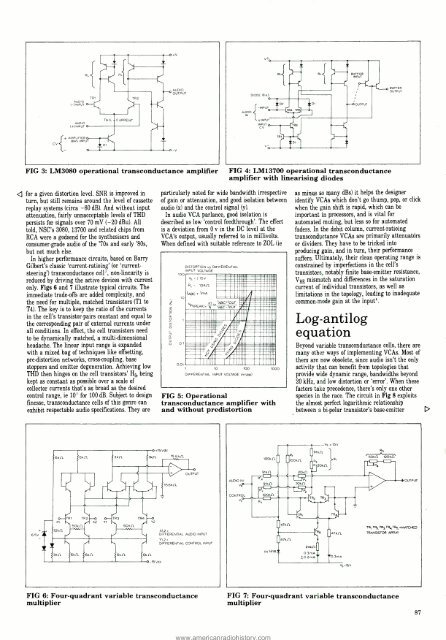
:AUDIO(- )INPUTTRITR2AUDIOOUTPUTAUDIO( +)INPUTTAILCURRENTVAMPLIFINPIERBIAS UTFIG 3: LM3080 operational transconductance amplifierQ for a given distortion level. SNR is improved inturn, but still remains around the level of cassettereplay systems (circa 60 dB). And without inputattenuation, fairly unnacceptable levels of THDpersists for signals over 70 mV (-20 dBu). Alltold, NSC's 3080, 13700 and related chips fromRCA were a godsend for the synthesisers andconsumer -grade audio of the '70s and early '80s,but not much else.In higher performance circuits, based on BarryGilbert's classic `current -ratioing' (or `current -steering') transconductance cell', non -linearity isreduced by driving the active devices with currentonly. Figs 6 and 7 illustrate typical circuits. Theimmediate trade -offs are added complexity, andthe need for multiple, matched transistors (T1 toT4). The key is to keep the ratio of the currentsin the cell's transistor -pairs constant and equal tothe corresponding pair of external currents underall conditions. In effect, the cell transistors needto be dynamically matched, a multi -dimensionalheadache. The linear input range is expandedwith a mixed bag of techniques like offsetting,pre -distortion networks, cross -coupling, basestoppers and emitter degeneration. Achieving lowTHD then hinges on the cell transistors' life beingkept as constant as possible over a scale ofcollector currents that's as broad as the desiredcontrol range, ie 10' for 100 dB. Subject to designfinesse, transconductance cells of this genre canexhibit respectable audio specifications.rThey are3k11i156kf7.particularly noted for wide bandwidth irrespectiveof gain or attenuation, and good isolation betweenaudio (x) and the control signal (y).In audio VCA parlance, good isolation isdescribed as low `control feedthrough'. The effectis a deviation from 0 v in the DC level at theVCA's output, usually referred to in millivolts.When defined with suitable reference to ZOL (ieDISTORTION vs DIFFERENTIALINPUT VOLTAGE100V515VD1..di0.01FIG 4: LM13700 operational transconductanceamplifier with linearising diodesM11111111..1R( = 10Kf1nnnn IIABC 1mAIN1111__UII/ /E11111 IKT 1ABC+,OUTVIN(PEAK (nE.`snnusac:'iiii'ABC -,OUTí wo 11momnB11.i11111111i1111P111111-M"::::: ":: -FAUNMOM 4'Ó IáAIIIM1111111.: :=I IM..IIIi1Ì 2 Inu .unn1MmI iM11111111111111111111M1111111110 100DIFFERENTIAL INPUT VOLTAGE (rnVpp)1000FIG 5: Operationaltransconductance amplifier withand without predistortion+15Vdc_15.6kROUTPUTas minus so many dBs) it helps the designeridentify VCAs which don't go thump, pop, or clickwhen the gain shift is rapid, which can beimportant in processors, and is vital forautomated muting, but less so for automatedfaders. In the debit column, current -ratioingtranscondtictance VCAs are primarily attenuatòrsor dividers. They have to be tricked intoproducing gain, and in turn, their performancesuffers. Ultimately, their clean operating range isconstrained by imperfections in the cell'stransistors, notably finite base -emitter resistance,VBE mismatch and differences in the saturationcurrent of individual transistors, as well aslimitations in the topology, leading to inadequatecommon -mode gain at the input'.Log -antilogequationBeyond variable transconductance cells, there aremany other ways of implementing VCAs. Most ofthen are now obsolete, since audio isn't the onlyactivity that can benefit from topologies thatprovide wide dynamic range, bandwidths beyond20 kHz, and low distortion or 'error'. When thesefactors take precedence, there's only one otherspecies in the race. The circuit in Fig 8 exploitsthe almost perfect logarithmic relationshipbetween a bi -polar transistor's base -emitterRSw501,(7 12Okf1OUTP,D6.5VTR3TR4X2 Ti Y25Okf7)(¿2DIFFERENTIAL AUDIO INPUTY1,2DIFFERENTIAL CONTROL INPUTI47kf724kf71TR,, TR, TRATR, TRS MATCHEDTRANSISTOR ARRAY6kR15 ddc0.3mÁ+02mÁVS-15VFIG 6: Four -quadrant variable transconductancemultiplierFIG 7: Four- quadrant variable transconductancemultiplier87
- Page 1:
June 1989STUDIOAND BROADCAST ENGINE
- Page 4 and 5:
Sony Broadcast& CommunicationsBroad
- Page 6 and 7:
NEUTRIKSWISSconnectorsFed up with w
- Page 8 and 9:
lLET USINTRODUCE YOUTO A FRIENDTHE
- Page 10 and 11:
®XSP56001R20B77G8824Ur*.......t+00
- Page 12 and 13:
MUSIC i RECORDINGLA B NEWSTelephone
- Page 14 and 15:
C/)WDudderidgeacquires FocusritePhi
- Page 16 and 17:
GLW Enterprisesacquires HarrisonSys
- Page 18 and 19:
AgenciesSynton of Holland have sign
- Page 20 and 21:
C :SOUND© GraphicAudio EditingFirs
- Page 22 and 23:
ContractsThe Home Service has recei
- Page 24 and 25:
1Soundlab active audio splitterSoun
- Page 26 and 27:
42'21 111H1H-"b9I Illlllll IIIIIIII
- Page 28 and 29:
The DC 24 MultiLFunctionDy, ñíami
- Page 30 and 31:
AlbRTW digital masteringsystemRTW h
- Page 32 and 33:
The round the world round of round
- Page 34 and 35:
,14GENELi CFINLAND, 7htaantie 17, P
- Page 36 and 37:
SolidStatelogic G Series NewsReal W
- Page 38 and 39:
SolidStateLogicNew Purpose - built,
- Page 40 and 41:
SolidStateLogicDi 'tal Audio NewsDi
- Page 42 and 43:
SolidStateLogicCompany NewsExpansio
- Page 44 and 45:
REPORTER JOURNALISTPRO -CASSETTE RE
- Page 46 and 47: THE ADVANTAGES of a STUDIOCONDENSER
- Page 48 and 49: AES HAMBURG=BY ANDY ROSE, DIRECTOR,
- Page 50 and 51: 1n seems easy enough,al sampling to
- Page 52 and 53: 14e last count the number ofBrent r
- Page 54 and 55: cthe question `What if we swapped t
- Page 56 and 57: aFIG 5Appearancehead finding audio
- Page 58 and 59: AKGacousCicsADVANCEDMICROPHONETECHN
- Page 60 and 61: 'Recently a few dealers have compla
- Page 62 and 63: tWl £Na«uvv«««:w,p/ N.»iH{t.M
- Page 64 and 65: Film -Tech PAM 42 portable audio mi
- Page 66 and 67: Q Concept, Soundmix and Multimix. H
- Page 68 and 69: d include from Cutec a switchable 1
- Page 70 and 71: d of broadcast NAB cartridge machin
- Page 72 and 73: 4GOLD LINEumaJAPORTABLE RTA1/3 OCTA
- Page 74 and 75: efflefingSoundtracs FMB series mixi
- Page 76 and 77: Auio...if you don't see what you wa
- Page 78 and 79: -nvasigh Midl'ladP9t/'knnIFveuuenaY
- Page 80 and 81: A STRONG TEAMD&R DAYNERwoinpThis co
- Page 82 and 83: ULTRASOUN DJanet Angus visits a Lon
- Page 84 and 85: The Recognized Standard in Audio Te
- Page 86 and 87: 4 The sample rate converter is used
- Page 88 and 89: www.americanradiohistory.comDSP THE
- Page 90 and 91: INTRODUCINGOUR NEWM0DEIrTèP325THE
- Page 92 and 93: VCASINVESTIGATEDPART ONEBen Duncan
- Page 94 and 95: Q root extractor or exponentiator.
- Page 98 and 99: Q voltage (VBE) and collector curre
- Page 100 and 101: '2)1)2). t)YJÌr2lYlá)`tÌ :% i) _
- Page 102 and 103: SINE WAVE1 2 3 4 5 6 7FREQUENCYSQUA
- Page 104 and 105: The studio was dark except for the
- Page 106 and 107: capacitance is fired by grounding.S
- Page 108 and 109: IZWQ U_VW1--Fostex D-20A technical
- Page 110 and 111: function by the toggle switch label
- Page 112 and 113: Other indicatorsand switchesThe maj
- Page 114 and 115: ConceptualdCDCfg114111wR-aatojuiai
- Page 116 and 117: Details of the Fostex DAT and timec
- Page 118 and 119: BSS DPR -502A user report on a MIDI
- Page 120 and 121: preserve the full sound of the drum
- Page 122 and 123: www.americanradiohistory.comSoundcr
- Page 124 and 125: the EQ section. It can be switched
- Page 126 and 127: AND BROADCAST ENGINEERINGYOUR SINGL
- Page 128 and 129: S1TUATIGIOACANTSALES ENGINEERWith B
- Page 130 and 131: RVICESSI TUATIONS VOCAwPORKY'S MAST
- Page 132 and 133: INDEX TO ADVERTISERSAbacusAdams Smi
- Page 134: REALISEYOURASPIRATIONSSTUDER'S COST