OBSAH
Inalfa Event Series Spoilers - Donmar
Inalfa Event Series Spoilers - Donmar
- No tags were found...

You also want an ePaper? Increase the reach of your titles
YUMPU automatically turns print PDFs into web optimized ePapers that Google loves.
Inalfa Event Spoiler Series Installation and Service ManualB. PrefaceB.1 Event Spoiler Operating InstructionsThe Event Spoiler can be operated in two modes Continuous and One Touch .Continuous mode allows the Event Spoiler to be operated by holding down the operating switch in either direction.Releasing the switch will stop the glass panel immediately.One Touch mode allows the Event Spoiler to be operated without holding the operating switch down and can becanceled by any switch activation.• To Open, tap the operating switch on the backside of the switch marked with a white spot. The glass panel will go to afully opened vent position. A second tap will fully open the roof. If desired, the sunshade can be closed in this position• To Close, tap the operating switch on the front side of the switch. The glass panel will move to the fully opened ventposition. A second tap will fully close the roof.Additional FeaturesAuto Close function allows the sunroof to close automatically when switching off the vehicles ignition. During the AutoClose function, simply depress the switch to cancel, this will return the glass panel to the position it was in prior to the start ofthe Auto Close function, depressing the switch again will reactivate the Auto Close.Protective Stop Position: The Event Spoiler Sunroof is also protected against obstructions fixated on top of the car. If theglass panel hits a hard object it will stop moving immediately, this is a new stop position. After taking the object from the roofof the car bring the roof to the full open position and hold the switch for five (5) seconds, the glass panel will move to theoriginal fully open position.B.2 Initialization ProcedureTo initialize, the following closed position must be defined.Turn on ignitionIn the closed position operate the front button of the switch until the relay clicking noise is noticed (Max 5 seconds).To complete the initalization process, the glass panel must be moved to the fully opened position using OneTouch mode.3 Preface
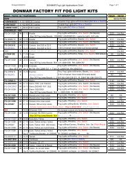
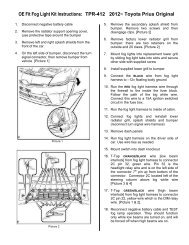
Inalfa Event Spoiler Series Installation and Service ManualC. Installation Instructionswww.inalfasunroofs.comC.1 Determine ApplicationDetermine the application by referring to the Assist Program or the Application Chart for thatparticular vehicle.Consideration should be given to dome lights and ribbed formed roof skins.If you are unsure of an application and you have access to the vehicle; the headliner mayneed to be removed if the vehicle is unfamiliar.C.2 Pre Installation InspectionBefore you proceed, check to insure that you have all the components for a completeinstallation. Also, insure that none of the components have been damaged in shipping.Check for the following:Spoiler, Sunshade, Louver, Substrate, Hardware BagAt this time, using a 12v power source, test the functionality of the sunroof unit.Note: Leave the glass panel in the closed position during installation.Do not remove the motor.To initialization the SCU see 'Initialization Procedure ' in the Preface Section.C.3 Vehicle Prep for InstallationDisconnect the negative side of the batteryProtective Covers (Interior)Place protective covers on the following:CarpetingSteering WheelInstrument PanelSeatsRemoval of Interior TrimRemove the following items:Sun visors / Retaining ClipsDome LampsCoat HooksProtective Covers (Exterior)Place protective covers on the following:HoodDoorsDeck LidExterior GlassRear of RoofClean Exterior4 Installation Instructions
Inalfa Event Spoiler Series Installation and Service ManualC. Installation InstructionsC.7 Mainframe / Clamp Frame Installation cont.Optional Method:Apply a 1/4" bead of non-corrosive silicone to the underside of the mainframe. Care shouldbe taken to insure a continuous bead.Position the mainframe into the roof opening from the outside of the vehicle.Clean off any excess silicone around the frame edge.C.7.2 Install the Mainframe to the Trim RingFrom inside the vehicle raise the clamping frame to the Mainframe. Attach the front of theclamping frame around the motor, then attach to the mainframe.Position the rear portion of the clamp frame to mounting frame and attach the retainingscrews.Insert shim at the rear of the opening, to insure proper spacing between the glass and themainframe, approximately 1/8" (3.30mm) thick.Caution: Over tightening the screws will cause the roof skin distortion and undertightening could cause improper compression.7 Installation Instructions
Inalfa Event Spoiler Series Installation and Service ManualC. Installation InstructionsC.9 Substrate Prep.C.9.1 Removing the Sunshade from the substratePull the sunshade forward. Using a hook tool release the side blocks on one side, lift andpull the sunshade from the guides.Tape the track guides with masking tape to avoid prolonged clean up.Pre spray glue to the leading edge for headliner retention.C.9.2 Substrate mountingInstall substrate to the mainframe using a T-20 torque bit driver.Install all 10 T-20 substrate retaining screws.9 Installation Instructions
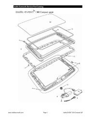
Inalfa Event Spoiler Series Installation and Service ManualC. Installation InstructionsC.10 Wrapping the SunshadeCut a 24 x 30 inch piece of headliner material and spray, with trim adhesive, the backsideand edges of the sunshade panel. Place the shade panel off to the side and spray the restof the headliner material with trim adhesive.Spray glue to the face side of the sunshade and headliner material.Return the shade panel to the glued side of the headliner material then turn the shade panelwith the headliner material over. Starting in the center smooth and pull the fabric from thecenter to the outer edges.Turn the shade panel over and adhere the material to the side edges as shown. Trim awayany extra material.Wrap the material over the rear and front edge of the sunshade.Trim material from the shade slide block holes and louvers for the shade handle.Install the handle with provided press nuts (4).Finished product10 Installation Instructions
Inalfa Event Spoiler Series Installation and Service ManualC. Installation InstructionsC.11 Wrapping the HeadlinerTrim the factory hardboard headliner; allowing for substrate clearance.Measure enough material to cover the headliner board.Apply trim adhesive to the back side of the new headliner material Allow 5 - 10 minutes forboth glues surfaces to set-up. (Glued surfaces will feel tacky to the touch)Use Headliner Material that meets FMVSS 302 Specification (Flammability)Trim the excess material around the outer edge, visors, consoles and handles of theheadliner board.Install the headliner into the vehicle.Pull the switch harness through he switch opening and connect the switch.Insert the switch into the substrate.Install the visors and retaining clips; insuring that the headliner is properly positioned.C.12 Wrapping Opening.Pre glue the headliner material in the area to be wrapped.Cut relief cuts in all four corners.Caution: Do not over cut the material for it may show.Pull and tack the headliner material to the leading edge.11 Installation Instructions
Inalfa Event Spoiler Series Installation and Service ManualC. Installation InstructionsC.12 Wrapping Opening Cont.Trim the headliner material leaving enough material for wrapping the leading edge.Tuck the material using a tucking tool.Complete interior build up.C.13 Sunshade InstallationPlace the Event Spoiler unit into the open position.From outside of the vehicle, position the sunshade clips into the track guides.Pull the sunshade forward to insure proper function.Cycle the Event Spoiler to test for proper function.Clean the interior of the vehicle.Water test the Event Spoiler.12 Installation Instructions
Inalfa Event Spoiler Series Installation and Service ManualNotes:13 Notes
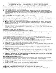
Inalfa Event Spoiler Series Installation and Service Manual14 inalfa EVENT 300 Compact QF
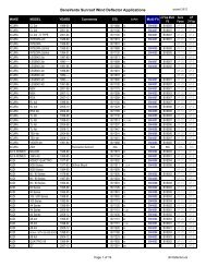
Inalfa Event Spoiler Series Installation and Service ManualIndex No Description Repair Code Part Number1 Trim Ring Assy w/ Fastening Clips TR300 2400444A702 Main Frame w/ Mechanism MF300QF 3800202A703 Clamp Frame w/ Trim Ring Brackets CF300QF 3800203A704 Locking Slider LH LSL 4110115A705 Locking Slider RH LSR 4110116A706 Set of Fastening Clips FC300 4180165C007 Screw Kit SK300 4180170A118 Wiring Harness Electronic WHE300 4200089A119 Motor Assy Electronic MTR300QF 5380040A7010 SCU SCU300QF 6070016A7011 Main Seal MS300QF 7400673A7012 Operating Switch OS300QF 8050050A7013 Glass Assy GA300QF 8840191A70Not shown on diagram:Butyl Seal BUTY 10800040A70Fitting Hardware Kit Electronic HKE300 4180172A11Set of Trim Ring Brackets4180171A1115 inalfa EVENT 300 Compact QF
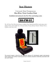
Inalfa Event Spoiler Series Installation and Service Manual16 inalfa EVENT 450 QF
Inalfa Event Spoiler Series Installation and Service ManualIndex No Description Repair Code Part Number1 Trim Ring Assy w/ Fastening Clips TR450QF 2400443C002 Wind Deflector Assy N/A3 Main Frame w/ Mechanism MF450QF 3800197C004 Clamp Frame w/ Trim Ring Bkts CF450QF 3800198C005 Locking Slider LH LSL 4110115A706 Locking Slider RH LSR 4110116A707 Screw Kit SK450QF 4180163A118 Set of Fastening Clips FC450QF 4180165C009 Wiring Harness Electronic WHE450QF 4200089A1110 Motor Assy Electronic MTR450QF 5380040A7011 SCU SCU450QF 6070016A7012 Main Seal MS450QF 7400672A7013 Rollo Assy RA450QF 7500012A7014 Operating Switch OS450QF 8050050A7015 Glass Assy GA450QF 8840190A70Not shown on diagram:Butyl Seal BUTY 10800040A70Fitting Hardware Kit Electronic HKE450QF 4180168A1117 inalfa EVENT 450 QF
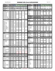
Inalfa Event Spoiler Series Installation and Service ManualOE/FF18 inalfa EVENT 450 OE
Inalfa Event Spoiler Series Installation and Service ManualOE/FFIndex No Description Repair Code Part Number1 Wrap Frame Assy WFA450OE 3800199A702 Wind Deflector Assy N/A3 Main Frame w/ Mechanism MF450OE 3800201A704 Clamp Frame Assy CF450OE 3800200C005 Locking Slider LH LSL 4110115A706 Locking Slider RH LSR 4110116A707 Screw Kit SK450OE 4180166A118 Wrap Frame Screws WFS450 4180167A119 Wiring Harness Electronic WHE450OE 4200089A1110 Motor Assy Electronic MTR450OE 5380040A7011 SCU SCU450OE 6070016A7012 Main Seal MS450OE 7400672A7013 Rollo Assy RA450OE 7500012A7014 Locking Strip LS450OE 7980003A7015 Operating Switch OS450OE 8050050A7016 Glass Assy GA450OE 8840190A7017 Protection Pads PP450OE 6100003A7018 Switch Plate Assy SPA450OE 6400308A70Not shown on diagram:Butyl Seal BUTY 10800040A70Fitting Hardware Kit Wrap Electronic HKE450OE 4180169A1119 inalfa EVENT 450 OE
Inalfa Event Spoiler Series Installation and Service Manual20 inalfa EVENT 450 HS
Inalfa Event Spoiler Series Installation and Service ManualIndex No Description Repair Code Part Number1 Cover-Assy P177 H/S CA450HS 2400479E412 Wind Deflector Assy N/A3 Main Frame w/ Mechanism HS MF450SS 3800206A704 Clamp Frame Assy CF450OE 3800200C005 Locking Slider LH LSL 4110115A706 Locking Slider RH LSR 4110116A707 Screw Kit SK450HS 4180166A118 Fastener Bag FB450HS 4180191C009 Wiring Harness Electronic WHE450HS 4200089A1110 Motor Assy Electronic MTR450SS 5380040A7011 SCU SCU450SS 6070016A7012 Main Seal MS450SS 7400672A7013 Operating Switch OS450SS 8050050A7014 Glass Assy GA450SS 8840190A7015 Panel-P177 Hardshade PHS450SS 6200970C4116 H/ware Bag Sunshade Spring HBSSP450HS 4180173A1117 Louver-Assy P177 H/S LA450HS 4980004A70Not shown on diagram:Butyl Seal BUTY 10800040A70Fitting Hardware Kit Wrap Electronic HKE450OE 4180169A11Kit-Base P177 H/S KHS450SS 4730156A00Kit-Base P177 Trim KT450SS 4730215A00Screw-P177 Hardshade SCR450HS 7310118A7021 inalfa EVENT 450 HS
Inalfa Event Spoiler Series Installation and Service ManualF. Service Set InstructionsF.1 Glass PanelRemoval:Cycle the glass panel into the open position. Allowing access to the four (4) T-25 torxscrews.Remove four (4) T-25 torx screws, save for new glass installation.Remove the Glass Panel.Install:Install the new glass panel using the existing four (4) T-25 glass screws. Apply a threadlock material before reattaching the screws.F.2 Sunshade Panel (450 HS only)Removal:Cycle the glass panel to full slide open position.Pull the sunshade forward.With a hook tool release the side blocks from one side, lift and pull the sunshade from thesunroof housing.Wrap the new sunshade with matching headliner material(see C10. Wrapping the Sunshade)Install:With the sunshade in position, insert the sliding blocks on one side, pull opposite thesliding blocks inward and engage into the mechanism guides.Re-install the Glass Panel (see D.2.1).F.3 Wind Deflector (450 series only)RemovalOpen the Glass Panel.Remove the plastic WD cover at the rear end of each WD spring.Deflect the wind deflector rearward and up to release from the mechanism guide.22 Service Guide
Inalfa Event Spoiler Series Installation and Service ManualF. Service Set InstructionsF.3 Wind Deflector cont.InstallInsert the wind deflector arms into slots in the mechanism guide.Pivot the wind deflector forward and downRe-attach the plastic wind deflector covers by snapping them into position.Close the glass panel to check for proper function.F.4 Locking SlidersRemovalRemove Glass Panel (see D.2.1)Remove both locking sliders from the mechanism by sliding it to the front. Ifat one side the locking slider is not broken break the part as shown in image.InstallSlide the new locking slider from the front side in abackwards movement on the mechanism.Click the front hook of the locking slider on the mechanism.Prior to re-installing the glass panel, fully cycle the mechanism. Return the mechanism tothe full open position afterwards.Re-install the Glass Panel (See D.2.1)F.5 Mechanism LH/RHRemovalRemove Glass Panel (see D.2.1).Remove the Headliner substrate assembly.Remove the motor connector from the SCU.Remove the clamp frame and motor; take the frame assembly out of the vehicle and laythe frame assembly upside down on a bench.Clean the roof skin of the vehicle23 Service Guide
Inalfa Event Spoiler Series Installation and Service ManualF. Service Set InstructionsF.5 Mechanism LH/RHRemoval continuedRemove the four plastic pop rivet caps using a hook tool.(450 Series only)Drill out the four rivets, retaining the mechanism guides to the mainframe.(450 Series only)Remove the mechanism guide and drive cable center plate T-25 torx screws.Remove the drive cable from the mainframe.Lift the guide and cable mechanism from the mainframe.InstallReplacement component.Position the new mechanism assemblies, drive cables and tubes. Ensure themechanisms are in the fully closed position. Align the drive tubes and return tubescorrectly.Apply super glue along the sides of each of the four tubes; bonding the tubes to theframe.Re-install the guide screws and the Drive Cable Center Plate.Re-install the frame assembly in the vehicle and mount clamp frame(See- C7 Mainframe / Clamp Frame Installation)Re-install the motor, ensure the mechanisms still are in the full closed position (lockingsliders fully forwards) and re-connect the connector to the SCU.Cycle the unit, checking for correct operation and alignment.Re-install the glass panel (See D.2.1)Re-install the substrate and headliner or trim ring(See- C.9.2 Substrate mounting.)24 Service Guide
Inalfa Event Spoiler Series Installation and Service ManualF. Service Set InstructionsF.6 Motor Removal / InstallTools required to remove the SCU & motor.1For 450 HS use the Scuw Driver tool.Disengage the switch from the headliner/trim ring.2Using a hook tool pull the material from backside of the hardboard. (450HS only)3 4Carefully peel back the headliner material to gain access to the attachment screws.(450 HS only)5Remove the T-25 screws retaining the bezel to the mainframe. (450 HS only)6Remove enough screws so the bezel can be deflected downwards, to gain access to themotor assembly. (450 HS only)725 Service Guide
Inalfa Event Spoiler Series Installation and Service ManualF. Service Set InstructionsF.6 Motor Removal / Install cont.Remove the motor from the mainframe by removing the three(3) T-25 screws.8Retain the three(3) T-25 screws for the motor replacement.9Remove the motor assembly.Re-install the motor following steps 10 thru 1.10Re-install the headliner.F.7 SCU Removal and ReplaceFollow the motor removal procedure steps 1 thru 7.Disengage the SCU from the mainframe.Unplug the harness connector from the SCU.Unplug the motor connector from the SCU and replace the SCU.Follow the removal procedures for reattaching the SCU and motor assembly.Re-install the headliner.Tuck the headliner material into position.26 Service Guide
Inalfa Event Spoiler Series Installation and Service ManualF. Service Set InstructionsF.8 Seal RemovalRemovalCycle the Glass Panel to full slide open position.Using a screwdriver, lift the seal section from the mainframe.Remove the seal section from the mainframe.Clean and remove any excess silicone from the seal retaining channel.InstallApply a 3mm bead of silicon adhesive in the outer corner of the frame groove.Apply an additional bead of silicon adhesive in the inner corner of the groove along thefront of the frame.Insert the new seal, starting in the four corners. equally dividing the seal.Insert the Seal in between the corners. Ensure that the seal is not pulled out or presseddown in the corners. Cycle the glass panel during the mounting of the seal; to achieveeasy access.Cycle the glass panel to closed position and allow for a minimal of 4 hours currying time.27 Service Guide
Inalfa EVENT Installation Manual and Service ManualG. Trouble Shooting GuideMechanical FailuresProblem Possible Cause SolutionPanel misaligned LH/RH Timing of drive cables incorrect Re-time drive cablesGlass panel stopping prematurely. Obstacle in mechanism or guide rail Remove obstacleCable ratchetingCheck the motor and cable tube atmotor bracket and motor insertAlign cable tube to motor bracket and reinstallmotor properly.Electrical FailuresProblem Possible Cause SolutionOperating of the sunroof is possible, noauto close, no one touchSCU makes clicking noise but panel willnot movePanel is sliding too slowly. With a 13.5vpower supply, the panel should not takemore than 7sec. To close from fullyopened position.SCU in degraded mode due tomalfunctionLow voltageWeak batteryMisaligned panel creating dragWeak motorDirty mechanismRefer to B.2. Re-initilization ProcedureCheck power supplyChange or replace motorClean and grease mechanism or replace.Rattling NoiseProblem Possible Cause SolutionHardshade Loose attachment screws Tighten all T-25 attachment screwsSunshade rattling Check for felt pads on sunshade Add felt pads to sunshadeRattle in motor area Loose screws on motor Tighten screws or replaceWind NoiseProblem Possible Cause SolutionExcessive wind noise when the panel is inthe closed positionPanel seal not tight to glass panelLocking slider broken, replace Locking SliderSeal deformed, replace sealWater LeaksProblem Possible Cause SolutionWater coming through panel openingarea or headliner wetPanel seal not tight to glass panelLocking slider broken, replace Locking SliderSeal deformed or damaged, replace seal28 Trouble Guide
Inalfa EVENT Installation Manual and Service ManualG. Trouble Shooting GuideTesting Electrical ComponentsMake sure that during the test of electrical components the Inalfa EVENT Spoiler is connected to a 12V source.If the roof is installed in a car, the battery needs to be connected and operable. During test period, the ignition/accessory switch mustbe on. This test can be accomplished with a voltage meter or test light.Inspect and make sure that the fuses are not blown.Cable harness and motor inspection requires the removal of the headliner.Wire Harness SCU to BatteryConnector Power on wire if ignition is off Power on wire if ignition is onWire number 1 (red) 12V 12VWire number 2 (black) Ground GroundWire number 3 (blue) 0V 12VMotorDisconnect the motor wire from the SCU. If the mechanism is jammed remove the motor from the frame. Use a double wire ofsufficient length, connect directly to battery and inspect the motor for proper operation in both directions. This is done by reversing theconnection of the double wire. The motor has an inbuilt thermal cut-out device that automatically switches the motor off during periodsof overload. After a cooling down period the motor will function properly.SCUTesting is covered in the electronic trouble chart. The following failures could be a result of a defective SCUNo action on continues operationOne Touch operation inoperativeAuto Close function inoperativeNo action on continues operationOne Touch operation inoperativeAfter replacing the SCU, the SCU must then be re-initialized. Proceed with the electronic trouble chart if the problem is not solved byinitialization.Re-initialization of the SCUTo re-initialize, the following closed position must be defined.Turn on ignition.In the closed position operate the front button of the switch until the relay clicking noise is noticed (Max 5 seconds).To complete the reinitalization process, the glass panel must be moved to the fully opened position using One Touch mode.29 Trouble Guide
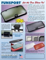
Inalfa EVENT Installation Manual and Service ManualH. Trouble ChartIs the motor running withignition switched on?no Is the switch illuminated? no Is the fuse of the red contact yes Has the fuse been replaced yes(ignition contact switched on).wire blown? ignition contactbefore?switched onFuse smaller than 20amps?yesMount a fuse of 20amps (red)yes yes no no noReplace FuseShort circuit in wire harness,replace wire harnessPower (12v) on red contactwire of SCU?noBreak or bad contact in wireharness between fuse andSCU, replace wire harnessor solve bad connection.yes Disconnect motor from yes Re-connect motor connector yesSCU. Check the correctto SCU and replace switch.functioning of the motor by Is the roof functioning normal?connecting the motor wiresnoto a separate power source.Is the motor functioning inboth directions?nonoRemove motor fromsunroof frame. Is the motorfunctioning in bothdirections?noMotor broken, replacemotor.yesSCU failure, replace SCUMechanical problem. Checkmechanism for obstruction orfailureSwitch failureIs the fuse of the blue ignitioncontact switched onyesHas the fuse been replacedbefore?yes Fuse smaller than 5 amps?yesMount a fuse of 5 amps (blue)noReplace switch, problemsolved?yesnoReplace FuseSwitch failurenoShort circuit in wireharness, replace wireharnessnoPower (12v) on blue contactwire of SCU?noBreak or bad contact in wireharness between fuse andSCU, replace wire harness orsolve bad connection.yesBreak or bad contact in flatcable between fuse andSCU, replace wire harnessor solve bad connection.30 Trouble Chart
Inalfa EVENT Installation Manual and Service ManualH. Trouble ChartIs the motor runningin both directions?yesnoDisconnect motor from SCU.Check the correct functioning ofthe motor by connecting themotor wires to a separate powersource.Is the motor functioning in bothdirections?yesyesRe-connect motor connectorto SCU and replace switch.Is the roof functioningnormal?nonoSCU failure, replace SCUSwitch failurenoRemove motor from sunroofyesframe. Is the motor functioning inboth directions?Mechanical problem. Checkmechanism for obstructionor failurenoMotor broken, replace motor.yes no Is the motor running for only a yes yesshort time after operating theswitch?Is the motor runningnormal?yesMotor connector not properlymounted. Removeconnector and mountproperly. Problem solved?noProblem solvedReplace motorIs the one touchfunctioning?yesnoRe-initialize SCU by running thesunroof to closed position andkeep-on pushing the switch. After3 seconds the SCU confirms reinitializationby kicking back.Problem solved?yesProblem solvednoReplace SCUIs it possible to openthe roof in itsmaximum openedposition?yesnoRe-initialize SCU by running thesunroof to closed position andkeep-on pushing the switch. After3 seconds the SCU confirms reinitializationby kicking back.Problem solved?yesProblem solvednoCan the sunroof be placed in allpositions using the manualoverride on the motor?noMechanical problem. Obstructionor failure of mechanism. Removeobstruction or solve failure.yesBlue wire is not connectedvia ignition. Search foranother contact wire which isswitched by the ignitioncontact.31 Trouble Chart
Inalfa EVENT Installation Manual and Service ManualH. Trouble ChartThe roof isexperiencing falsereversal during onetouch or auto closeoperationnoRe-initialize SCU by running thesunroof to closed position andkeep-on pushing the switch. After3 seconds the SCU confirms reinitializationby kicking back.Problem solved?yesProblem solvedyesnoFalse reversal also occurs duringone touch closing motion?yes Sunroof does not close also yes Remove glass panel and nonot after completing the 5 test the sunroof. Problemretry closing motionssolved?Obstacle in mechanism.nonoHigh resistance ofmechanism whereby the antitrap protection is activated.Clean and lubricatemechanism with Molycoatbased grease.False reversal only occurs duringauto-closeyesHigh resistance ofmechanism whereby the antitrap protection is activated.Clean and lubricatemechanism with Polycoatbased grease.Is the auto closefunctioning?noyesElectronics Fully Tested and Okay.Remaining problems are not causedby the SCU, Motor, Wire harness orSwitch. Please continue with themechanical trouble shooting guide.Power (12v) on blue wire SCUwith ignition off?noReplace SCUyesBlue wire is not connectedvia ignition. Search foranother contact wire which isswitched by the ignitioncontact.32 Trouble Chart
Inalfa Event Spoiler Series Installation and Service ManualI. Inspection SheetAn inspection report will help reduce the number of complaints from your customer. Be sure the vehicle is clean and the OwnersManual is placed in the glove box prior to delivery.Inspection SheetSerial #:Date:Yr/Make/Model:Inspection by:VH#:Dealer:Mileage:Installation by:Stock #: VIN #:Type of Roof: Wind Deflector: Yes NoPower Wires: Hot Switched Switch Location:Cut line:Headliner Used:Inspection before InstallOK REJECT REJECTION OK'd1. Examine entire vehicle for dents, dings and scratches2. Check all electrical functions of vehicle3. Sign off on inspection form Initial:4. If defects are found contact sunroof manager or sales Dealer initial:manager and have them sign off on our inspectionreport.In-process inspection (Before Headliner)1. Wiring glued and taped correctly2. Check for correct wiring procedure and functionality3. Check dome light for proper functions4. Note defect and report to installer and supervisor5. After correction, re-inspect and sign form Initial:Inalfa Event Spoiler Series Installation and Service ManualOK REJECT REJECTION OK'd33 Inspection Sheet
Inalfa Event Spoiler Series Installation and Service ManualI. Inspection SheetInspection SheetFinal Inspection1. Water test Event Spoiler2. All plastic trim and components are properly installed?3. Top of roof is cleaned and waxed?4. Interior is cleaned of debris and glue (metal shavings in seat crevice)?5. Check for any tools left in car6. Roof operates properly:Roof closes from open with one touchRoof closes from vent with one touchRoof closes from open with auto closeRoof closes from vent with auto closeRoof auto-reverses from vent to closeRoof auto-reverses from open to close7. Interior lights work:8. Glass panel is clean:InsideOutside9. Test drive:No wind noiseNo rattles with roof shutNo rattles with roof open10. Make sure switch is secure.OK REJECT REJ OKED34 Inspection Sheet