LonWorks Nodes - Douglas Lighting Control
LonWorks Nodes - Douglas Lighting Control
LonWorks Nodes - Douglas Lighting Control
- No tags were found...

Create successful ePaper yourself
Turn your PDF publications into a flip-book with our unique Google optimized e-Paper software.
or computer have to be<br />
self-configured networks.<br />
Choose one node to be the<br />
network manager with this<br />
switch.<br />
SELECT<br />
MASTER<br />
SWITCH<br />
A<br />
ON<br />
OVERRIDE<br />
OFF<br />
OVERRIDE<br />
non-polarized, 78Kbps)<br />
B<br />
= H<br />
+ A HJEBEA @<br />
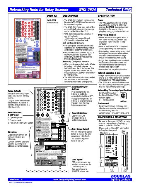
Networking Node for Relay Scanner<br />
Relay Outputs<br />
24 output terminals (12 per<br />
side), are provided for relay<br />
control.<br />
<strong>Douglas</strong> 2-wire switches can<br />
be connected in parallel to<br />
permit individual control of a<br />
relay by switch.<br />
Select Buttons<br />
& LED's for:<br />
1) Operating mode<br />
2) Program mode<br />
3) Flick Warn before OFF Option<br />
Directions<br />
Directions are printed on<br />
keypad for handy user<br />
reference.<br />
<strong>Control</strong>s on WNX-2624 are<br />
used for reviewing node<br />
address and switch codes.<br />
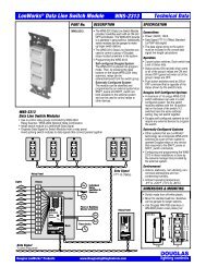
PART No.<br />
WNX-2624<br />
Network Node<br />
DESCRIPTION<br />
WNX-2624<br />
<br />
The WNX-2624 Network Node permits<br />
<strong>Douglas</strong> WRS-2224 Relay Scanners to<br />
be networked together.<br />
<br />
The WNX-2624 Node uses state-of-theart<br />
<strong>LonWorks</strong>® networking technology<br />
and is LonMark® certified (3.1).<br />
■<br />
WNX-2624 nodes can be networked in<br />
one of 2 methods.<br />
1) Self-configured network (default)<br />
2) Externally configured network<br />
Self-Configured Networks<br />
<br />
Self-configured networks are ideal for<br />
expanding the number of relay outputs<br />
controlled by a scanner switch input.<br />
<br />
When networked, the switch input of a<br />
scanner has global reach and can<br />
control any quantity of relay outputs<br />
throughout the system.<br />
Externally Configured Networks<br />
<br />
Other control systems that use <strong>LonWorks</strong><br />
technology can digitally integrate the<br />
WNX-2624 as a part of that system. This<br />
requries that the other system has the<br />
necessary features, software and interface<br />
for lighting control.<br />
<br />
The WNX-2624 node is LonMark certified,<br />
and will accept all the <strong>LonWorks</strong><br />
commands relevent for lighting control.<br />
Individual Output<br />
Buttons<br />
In operating mode, use<br />
buttons to switch the<br />
connected relay ON or OFF.<br />
In programming mode, use<br />
buttons to enter or remove<br />
the relay from the input<br />
being programmed.<br />
Override Buttons<br />
Use ON and OFF<br />
override buttons to<br />
switch relay groups.<br />
Relay Group Select<br />
Use the relay group select<br />
button to choose the relay<br />
group input 1,2,3,4 or 5.<br />
The selected input will<br />
have its led ON.<br />
6.5"<br />
(165)<br />
Technical Data<br />
SPECIFICATION<br />
Power<br />
<br />
The WNX-2624 network node obtains<br />
power from the host WRS-2224 relay<br />
scanner. CAUTION: Always disconnect<br />
24VAC from the scanner prior to<br />
plugging/unplugging the WNX-2624 unit.<br />
Wire Type & Method<br />
<br />
<strong>Nodes</strong> are connected together with a 2-<br />
wire cable. Use 16 AWG, twisted pair,<br />
unshielded cable. Stranded or solid<br />
conductor.<br />
<br />
Refer to "INSTALLATION - <strong>LonWorks</strong><br />
Data Signal Wiring" for more details.<br />
<br />
Free topology network wiring is supported.<br />
Data signal can be wired with branches<br />
and tees. Overall network wire length<br />
should not exceed 1650 feet (500m).<br />
<br />
Longer data signal lengths are possible if<br />
devices are connected in a serial bus.<br />
Optionally a repeater can be used to<br />
increase data signal length.<br />
<br />
Connections are not polarity sensitive.<br />
Network Operation & Size<br />
<br />
Simple basic networks are self-configured<br />
and up to 24 nodes can exist in a system<br />
(WNX-2624 and WNS-2308 nodes).<br />
<br />
The WNX-2624 and WNS-2308 nodes<br />
can also be integrated into other systems<br />
that use the <strong>LonWorks</strong> technology.<br />
Networking Technology Specification<br />
<br />
<strong>LonWorks</strong>® technology<br />
LonMark® Certified (V3.1).<br />
<br />
Network signal:<br />
FTT-10 Transceiver.<br />
Environment<br />
<br />
Environment: Indoors, stationary, nonvibrating,<br />
non-corrosive atmosphere and<br />
non-condensing humidity.<br />
<br />
Ambient temp: +15°to +120°F (-10° to +50°C)<br />
DIMENSIONS & MOUNTING<br />
<br />
Be sure to disconnect 24VAC from relay<br />
scanner before plugging/unplugging<br />
network node into scanner.<br />
<br />
Mount node to 35mm DIN rail installed<br />
in <strong>Douglas</strong> relay panel. Side<br />
Plan View<br />
View<br />
1 1<br />
2<br />
3 3<br />
4<br />
5 5<br />
6<br />
7 7<br />
8<br />
9 9<br />
10<br />
11 11<br />
12<br />
2<br />
4<br />
6<br />
8<br />
10<br />
12<br />
14<br />
16<br />
18<br />
20<br />
22<br />
24<br />
WRS-2224<br />
Relay<br />
Scanner<br />
13<br />
15<br />
17<br />
19<br />
21<br />
23<br />
13<br />
14<br />
15<br />
16<br />
17<br />
18<br />
19<br />
20<br />
21<br />
22<br />
23<br />
24<br />
W B<br />
1<br />
2<br />
3<br />
Sw B<br />
Inputs 45<br />
B<br />
w<br />
.<strong>Douglas</strong>LIghting<strong>Control</strong>s.comwww.<strong>Douglas</strong><strong>Lighting</strong><strong>Control</strong>s.com<br />
Data Signal<br />
FTT-10 transceivers are<br />
used to communicate the<br />
<strong>LonWorks</strong> protocol.<br />
Data signal cable is<br />
#16AWG, twisted pair,<br />
2.5"<br />
(64)<br />
SERVICE &<br />
ERASE<br />
NET MANAGER SELECT<br />
Networks without a scheduler<br />
LOOK-UP BUTTONS<br />
(Self-configured networks only)<br />
NODE ADDRESS SWITCH CODE<br />
WNX-2624<br />
Network Node<br />
ON<br />
OFF<br />
4.0"<br />
(103)<br />
LON WORKS<br />
NETWORK SIGNAL<br />
(FTT-10A Transceiver,<br />
1.75"<br />
(45)<br />
Interfaces 3.1<br />
C-3-1,2,3,4 -Systems, <strong>LonWorks</strong> Products<br />
www.<strong>Douglas</strong><strong>Lighting</strong><strong>Control</strong>s.com
FLICK<br />
PGM<br />
Networking Node with 8 Inputs<br />
Hardware & Switching Mode Options<br />
The table below is printed on the<br />
membrane key pad for easy reference.<br />
(The WNS-2308 is shown with the peelaway<br />
description label applied)<br />
Below is a reprint of the table to show the<br />
different hardware types and switching<br />
modes available from the keypad of the<br />
WNS-2308.<br />
In many cases, other systems are<br />
integrated with a contact closure. Use the<br />
table to determine the appropriate<br />
hardware type for the control supplied.<br />
Sw Mode<br />
. . O<br />
O<br />
. E? <br />
Hardware Type<br />
) + <br />
) + . .<br />
) + + . .<br />
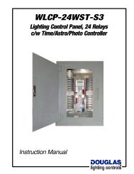
PART No.<br />
WNS-2308<br />
Eight Input Node<br />
DESCRIPTION<br />
WNS-2308<br />
<br />
The WNS-2308 Input Node provides<br />
EIGHT inputs that can control any group<br />
of relays in a <strong>Douglas</strong> system using<br />
networked WRS-2224 scanners.<br />
<br />
The inputs of the WNS-2308 can each be<br />
configured to be compatible with a variety<br />
of hardware types and can be configured<br />
to operate in a specific manner. The<br />
default configuration is: <strong>Douglas</strong> 2wire<br />
relay switch operating in the ON/OFF<br />
mode. Please refer to the table below for<br />
the complete list of hardware types and<br />
switch modes available.<br />
<br />
The WNS-2308 uses state-of-the-art<br />
<strong>LonWorks</strong> ® networking technology and<br />
LonMark certified control objects for<br />
lighting control.<br />
<br />
The WNS-2308 Input Node can be<br />
used in one of 2 methods:<br />
1) Self configured Network (default)<br />
2) Externally configured Network<br />
Self-Configured Networks<br />
<br />
Use in a self cofigured network to add<br />
inputs.<br />
Externally configured networks<br />
<br />
Other controls systems that use<br />
<strong>LonWorks</strong> technology can digitally<br />
integrate the WNS-2308 as a part of<br />
the other system.<br />
Master Switch<br />
Override Buttons<br />
Use input buttons A<br />
to H to switch inputs<br />
ON/OFF.<br />
Led's show status of<br />
relay group<br />
assigned to the<br />
input.<br />
Technical Data<br />
SPECIFICATION<br />
Power<br />
<br />
24VAC, 100mA<br />
Wire Type & Method<br />
<br />
<strong>Nodes</strong> are connected together with a 2-<br />
wire cable. Use 16 AWG, twisted pair,<br />
unshielded cable. Stranded or solid<br />
conductor.<br />
<br />
Refer to "INSTALLATION - <strong>LonWorks</strong><br />
Data Signal Wiring" for more details.<br />
<br />
Free topology network wiring is supported.<br />
The data signal can be wired with tees and<br />
branches. Overall network wire length<br />
should not exceed 1650 feet (500m).<br />
<br />
Longer data signal lengths are possible if<br />
devices are connected in a serial bus.<br />
Optionally, a repeater can be used to<br />
increase data signal length.<br />
<br />
Connections are not polarity sensitive.<br />
Network Operation & Size<br />
<br />
Simple basic networks are self-configured<br />
and up to 24 nodes can exist in a system.<br />
(WNX-2624 and WNS-2308 nodes).<br />
<br />
The WNX-2624 and WNS-2308 nodes<br />
can also be integrated into larger systems<br />
that use the <strong>LonWorks</strong> technology.<br />
Networking Technology Specification<br />
<br />
<strong>LonWorks</strong> ® technology<br />
LonMark ® Compliant<br />
<br />
Network signal:<br />
FTT-10 Transceiver.<br />
Environment<br />
<br />
Environment: Indoors, stationary, nonvibrating,<br />
non-corrosive atmosphere and<br />
non-condensing humidity.<br />
<br />
Ambient temp: +15° to +120°F (-15° to +50°C)<br />
DIMENSIONS & MOUNTING<br />
<br />
The WNS-2308 mounts to 35mm DIN rail<br />
in <strong>Douglas</strong> relay panel.<br />
Plan View<br />
Side<br />
View<br />
6 E A K J<br />
6 E A K J . E? <br />
, A = O . .<br />
, A = O . . . E? <br />
, A = O <br />
0 K I A A A F E C <br />
9 E 5 A JHO <br />
4 A C K = H . .<br />
4 A @ . .<br />
Sw Mode<br />
) + + . . <br />
) + + A<br />
) + + . . A<br />
) + + A <br />
) + + A . .<br />
, K C = I M EHA 5 M EJ? D<br />
, + 2 I . . A C <br />
, + 2 I A C . .<br />
, + 5 J= JK I 5 EC = <br />
, EI = > A @<br />
Hardware Type<br />
Select Buttons<br />
& LEDs for:<br />
1) Program mode<br />
2) Hardware options<br />
3) Input switching mode settings<br />
including the flick warn option.<br />
4) Input # and unit ID settings<br />
Directions<br />
Basic programming<br />
directions are printed<br />
on keypad for handy<br />
user reference.<br />
Detailed directions for<br />
specialized settings<br />
are in user manual.<br />
Data Signal<br />
FTT-10 transceivers are<br />
used to communicate the<br />
<strong>LonWorks</strong> protocol.<br />
Wiring is simple 16AWG<br />
twisted pair, unshielded<br />
wire, stranded or solid.<br />
6.5"<br />
(165)<br />
WNS-2308<br />
Network Node with<br />
8 Inputs<br />
NODE<br />
ID<br />
INPUTS<br />
B<br />
D<br />
F<br />
H<br />
INPUT<br />
CODE<br />
A<br />
C<br />
E<br />
G<br />
4.0"<br />
(103)<br />
B<br />
W<br />
B<br />
A B cg<br />
Data<br />
Signal<br />
1.75"<br />
(45)<br />
Interfaces 3.2<br />
C-3-1,2,3,4 -Systems, <strong>LonWorks</strong> Products<br />
www.<strong>Douglas</strong><strong>Lighting</strong><strong>Control</strong>s.com
A<br />
B<br />
C<br />
D<br />
E<br />
F<br />
G<br />
H<br />
NODE<br />
FLICK PGM<br />
INPUT<br />
ID CODE<br />
B<br />
A B cg<br />
FLICK<br />
WARN<br />
OPTION<br />
SERVICE &<br />
ERASE<br />
PROGRAM<br />
MODE<br />
1<br />
13<br />
2 14<br />
3<br />
15<br />
4 16<br />
5<br />
17<br />
6 18<br />
7<br />
19<br />
8 20<br />
9<br />
21<br />
10 22<br />
11<br />
23<br />
12 24<br />
NORMAL<br />
MODE<br />
NET MANAGER SELECT<br />
Networks without a scheduler<br />
or computer have to be<br />
self-configured networks.<br />
Choose one node to be the<br />
network manager with this<br />
switch.<br />
SELECT<br />
MASTER<br />
SWITCH<br />
FLICK<br />
WARN<br />
OPTION<br />
ON<br />
OVERRIDE<br />
OFF<br />
OVERRIDE<br />
LOOK-UP BUTTONS<br />
(Self-configured networks only)<br />
NODE ADDRESS SWITCH CODE<br />
ON<br />
OFF<br />
LON WORKS<br />
NETWORK SIGNAL<br />
(FTT-10A Transceiver,<br />
non-polarized, 78Kbps)<br />
A<br />
B<br />
= H<br />
+ A HJEBEA@<br />
PROGRAM<br />
MODE<br />
NORMAL<br />
MODE<br />
NET MANAGER SELECT<br />
Networks without a scheduler<br />
or computer have to be<br />
self-configured networks.<br />
Choose one node to be the<br />
network manager with this<br />
switch.<br />
SELECT<br />
MASTER<br />
SWITCH<br />
ON<br />
OVERRIDE<br />
OFF<br />
OVERRIDE<br />
LOOK-UP BUTTONS<br />
(Self-configured networks only)<br />
NODE ADDRESS SWITCH CODE<br />
ON<br />
OFF<br />
(FTT-10A Transceiver,<br />
non-polarized, 78Kbps)<br />
A<br />
B<br />
= H<br />
+ A HJEBEA @<br />
FLICK<br />
WARN<br />
OPTION<br />
SERVICE &<br />
ERASE<br />
PROGRAM<br />
MODE<br />
1<br />
13<br />
2 14<br />
3<br />
15<br />
4 16<br />
5<br />
17<br />
6 18<br />
7<br />
19<br />
8 20<br />
9<br />
21<br />
10 22<br />
11<br />
23<br />
12 24<br />
NORMAL<br />
MODE<br />
NET MANAGER SELECT<br />
Networks without a scheduler<br />
or computer have to be<br />
self-configured networks.<br />
Choose one node to be the<br />
network manager with this<br />
switch.<br />
SELECT<br />
MASTER<br />
SWITCH<br />
ON<br />
OVERRIDE<br />
OFF<br />
OVERRIDE<br />
LOOK-UP BUTTONS<br />
(Self-configured networks only)<br />
NODE ADDRESS SWITCH CODE<br />
ON<br />
OFF<br />
LON WORKS<br />
NETWORK SIGNAL<br />
(FTT-10A Transceiver,<br />
non-polarized, 78Kbps)<br />
A<br />
B<br />
= H<br />
+ A HJEBEA@<br />
A<br />
B<br />
C<br />
D<br />
E<br />
F<br />
G<br />
H<br />
NODE<br />
FLICK<br />
INPUT<br />
PGM ID CODE<br />
B<br />
A B cg<br />
FLICK<br />
WARN<br />
OPTION<br />
SERVICE &<br />
ERASE<br />
PROGRAM<br />
MODE<br />
1<br />
13<br />
2 14<br />
3<br />
15<br />
4 16<br />
5<br />
17<br />
6 18<br />
7<br />
19<br />
8 20<br />
9<br />
21<br />
10 22<br />
11<br />
23<br />
12 24<br />
NORMAL<br />
MODE<br />
NET MANAGER SELECT<br />
Networks without a scheduler<br />
or computer have to be<br />
self-configured networks.<br />
Choose one node to be the<br />
network manager with this<br />
switch.<br />
SELECT<br />
MASTER<br />
SWITCH<br />
ON<br />
OVERRIDE<br />
OFF<br />
OVERRIDE<br />
LOOK-UP BUTTONS<br />
(Self-configured networks only)<br />
NODE ADDRESS SWITCH CODE<br />
ON<br />
OFF<br />
LON WORKS<br />
NETWORK SIGNAL<br />
(FTT-10A Transceiver,<br />
non-polarized, 78Kbps)<br />
A<br />
B<br />
= H<br />
+ A HJEBEA@<br />
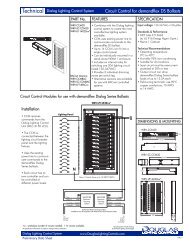
<strong>Douglas</strong> <strong>LonWorks</strong> Products<br />
Technical Data<br />
Lights<br />
Data Signal<br />
Terminator<br />
- Optional<br />
- Install near<br />
center of<br />
data signal<br />
WNT<br />
2999<br />
Input <strong>Nodes</strong><br />
Used for simple hardwired<br />
connections to networked inputs<br />
Data<br />
Signal<br />
A B cg<br />
Relay Panel<br />
Relays<br />
4<br />
4<br />
4<br />
4<br />
4<br />
4<br />
4<br />
4<br />
4<br />
4<br />
4<br />
4<br />
WNS-2308<br />
Network Node with<br />
8 Inputs<br />
INPUTS<br />
Data<br />
Signal<br />
1<br />
2<br />
3<br />
4<br />
5<br />
6<br />
7<br />
8<br />
9<br />
10<br />
1<br />
2<br />
3<br />
4<br />
5<br />
6<br />
7<br />
8<br />
9<br />
10<br />
11<br />
12<br />
1<br />
2<br />
3<br />
4<br />
5<br />
6<br />
7<br />
8<br />
9<br />
10<br />
11<br />
12<br />
13<br />
14<br />
15<br />
16<br />
17<br />
18<br />
19<br />
20<br />
21<br />
22<br />
23<br />
24<br />
WRS-2224<br />
Relay<br />
Scanner<br />
SERVICE &<br />
ERASE<br />
Sw<br />
Inputs<br />
WNX-2624<br />
Network Node<br />
13<br />
14<br />
15<br />
16<br />
17<br />
18<br />
19<br />
20<br />
21<br />
22<br />
11<br />
23<br />
12<br />
24<br />
W B<br />
WRS-2224<br />
Relay<br />
1<br />
2<br />
Scanner 3<br />
Sw B<br />
Inputs 45<br />
B<br />
WNX-2624<br />
Network Node<br />
Scanner/Node<br />
Combination<br />
13<br />
14<br />
15<br />
16<br />
17<br />
18<br />
19<br />
20<br />
21<br />
22<br />
23<br />
24<br />
W B<br />
1<br />
2<br />
3<br />
B 45<br />
B<br />
LON WORKS<br />
NETWORK SIGNAL<br />
Self-managed systems<br />
of up to 24 nodes can exist<br />
W<br />
B<br />
WTP-4408<br />
WTP-<br />
A B C D<br />
1 2 3<br />
Esc 1 2 3<br />
4 5 6<br />
4408<br />
47 58 69<br />
7 0 8 9<br />
0<br />
Sensor<br />
Sensor<br />
Telephone Interface<br />
Dial-in to actuate any of the<br />
256 relay groups ON or OFF.<br />
WTI-2331<br />
Clr<br />
W<br />
B12345678<br />
1<br />
2<br />
3<br />
4<br />
5<br />
6<br />
7<br />
8<br />
9<br />
10<br />
Scanner<br />
Node<br />
13<br />
14<br />
15<br />
16<br />
17<br />
18<br />
19<br />
20<br />
21<br />
22<br />
11<br />
23<br />
12<br />
24<br />
W B<br />
WRS-2224<br />
Relay<br />
1<br />
2<br />
Scanner 3<br />
Sw B<br />
Inputs 45<br />
B<br />
WNX-2624<br />
Network Node<br />
WNS-2308<br />
Network Node with<br />
8 Inputs<br />
INPUTS<br />
Data<br />
Signal<br />
W B<br />
5 M<br />
5 M<br />
Building<br />
Automation<br />
Contact<br />
Interfaces<br />
Individual<br />
Relay<br />
Switches &<br />
Sensors<br />
Floor or Building<br />
Master switches<br />
Time clocks<br />
Optional Integrated Systems<br />
<strong>Douglas</strong> <strong>LonWorks</strong> products are compliant to LonMark standards.<br />
Larger systems that use <strong>LonWorks</strong> technology can integrate <strong>Douglas</strong><br />
relay panels as a part of the larger system. The PC computer and<br />
integration process is performed by the suppliers of integrated systems.<br />
1<br />
2<br />
3<br />
4<br />
5<br />
6<br />
7<br />
8<br />
9<br />
10<br />
13<br />
14<br />
15<br />
16<br />
17<br />
18<br />
19<br />
20<br />
21<br />
22<br />
11<br />
23<br />
12<br />
24<br />
W B<br />
WRS-2224<br />
Relay<br />
1<br />
2<br />
Scanner 3<br />
Sw B<br />
Inputs 45<br />
B<br />
5 M<br />
5 M<br />
Data Signal<br />
#16 AWG, twisted pair, no shield<br />
WNX-2624<br />
Network Node<br />
CONNECTIONS<br />
<strong>Douglas</strong> relays and switches can be easiliy networked by using<br />
relay scanners equipped with network nodes. Local switches and<br />
sensors are still connected directly to relays and system wide<br />
switches/timers are connected to the inputs of the scanner/node<br />
combination.<br />
For system wide control of relays, connect a standard <strong>Douglas</strong> 2-<br />
wire switch and/or timer output to a scanner input. By using the<br />
membrane buttons built into the scanners, the relays controlled by<br />
an input are easily selected or de-selected.<br />
Each input of a scanner is unique. That is, input 1 of scanner 1<br />
can be set to control relays connected to scanners 1,2,3 etc.<br />
Input 1 of scanner 2 can be set to control a different group of<br />
relays that are connected to scanners 1,2,3 etc.<br />
By attaching a WNX-2624 network node to a WRS-2224 relay<br />
scanner, a simple, self-managed network can be established.<br />
The WNX-2624 nodes are connected together with a nonpolarized<br />
data signal that can be connected to the devices in<br />
either way.<br />
Total data signal length should not exceed 1650 feet (500m). If<br />
longer lengths are required (to a maximum of 7000 ft./2700m),<br />
wire the data signal from node-to-node in sequence (no tees or<br />
branches) or use a repeater.<br />
The WNX-2624 Scanner Node is LonMark certified to ensure<br />
reliable, predictable operation with other control systems that<br />
integrate <strong>Douglas</strong> relay panels as a part of their system.<br />
APPLICATION<br />
Simple, Self-configured Networks<br />
A self configured network only requires the network nodes to be<br />
plugged into the relay scanners and connected together via data<br />
signal. For one of the network nodes, set the network manager<br />
switch to "ON" and ensure that the rest of the switches are OFF.<br />
The node with the switch set to ON performs the network<br />
manager functions of configuration and address assignment.<br />
Use the membrane key pads built into the scanners to set which<br />
relays are controlled by an input. Any relay output that is part of<br />
the network can be programmed to an input.<br />
Each relay scanner has 5 inputs and 24 relay outputs. If additional<br />
inputs are required at a location, use the WNS-2308 EIGHT Input<br />
Networking Node.<br />
A self-configured system can support up to 24 nodes. This<br />
provides over 500 relay outputs and 120 inputs.<br />
The flick warn and time out options supported by a stand-alone<br />
WRS-2224 Relay Scanner are also supported on the selfconfigured<br />
network. If the input has an option selected with the<br />
keypad of the WRS-2224, the system wide relay group will have the<br />
same feature. The WNS-2308 also supports the flick warn feature.<br />
The WNS-2308 unit has additional features that allow the inputs to<br />
accept control from devices that do not use the <strong>Douglas</strong> 2wire<br />
switching method. Contact closures of maintained or momentary<br />
nature are easily interfaced to the WNS-2308.<br />
Externally Configured Networks<br />
<strong>Douglas</strong> <strong>LonWorks</strong> based products can be configured and<br />
controlled by an external host system that uses the <strong>LonWorks</strong><br />
standards. For programming and operating details of such<br />
systems, please refer to the documentation of the host system.<br />
Interfaces 3.3<br />
C-3-1,2,3,4 -Systems, <strong>LonWorks</strong> Products<br />
www.<strong>Douglas</strong><strong>Lighting</strong><strong>Control</strong>s.com
<strong>Douglas</strong> <strong>LonWorks</strong> Products<br />
APPLICATION (continued)<br />
Integrated Systems<br />
The <strong>LonWorks</strong> technology used by the <strong>Douglas</strong> Scanner/Node<br />
combination is a non-proprietary, open-architecture standard for<br />
building control networks. Other <strong>LonWorks</strong> based systems can<br />
incorporate a <strong>Douglas</strong> lighting control panel as a part of the other<br />
system provided the other system supports lighting controls.<br />
<strong>LonWorks</strong>® TECHNOLOGY<br />
To integrate different manufacturers devices and systems at a<br />
network level demands that common standards are in place today<br />
and in the future. The <strong>LonWorks</strong> technology provides a stable,<br />
common and open networking standard.<br />
<strong>Douglas</strong> <strong>Lighting</strong> <strong>Control</strong>s is a LonMark<br />
partner and we have developed our <strong>LonWorks</strong><br />
products to comply to the LonMark certification<br />
standards for open systems. This ensures our<br />
customers reliable and predictable<br />
performance when integrating <strong>Douglas</strong> product<br />
with other systems.<br />
Basics for Systems Integrators<br />
For building control designs that wish to take advantage of<br />
integrated systems, <strong>Douglas</strong> products can be integrated as a part<br />
of a greater system that uses the <strong>LonWorks</strong> network platform.<br />
LNS plugins are available for control and configuration of the<br />
objects listed in the table below. The LNS plug-ins are written in<br />
Visual Basic and are designed to plug-in to the LNS software<br />
engine used by many <strong>LonWorks</strong> Integrators.<br />
For more information visit: www.<strong>Douglas</strong><strong>Lighting</strong><strong>Control</strong>s.com<br />
LonMarked Variables used by <strong>Douglas</strong> Products<br />
Functional Profile (Object)<br />
Network Variable & Type<br />
<strong>Lighting</strong> Panel <strong>Control</strong>ler (LPC) nviGroup/nvoGroupFb<br />
(This object receives group commands, SNVT_Scene<br />
activates relay groups and returns<br />
status on relay groups.<br />
The trigger would be from a Scene Panel Object.)<br />
Scene Panel<br />
nvoScene/nviScenFb<br />
(This object issues group commands SNVT_Scene<br />
and receives the relay group status.<br />
The typical destination would be an LPC Object)<br />
Actuator (24 objects per node) nviLampValue/nvoLampValueFb<br />
(This object receives commands from a SNVT_Switch<br />
switch to activate a relay and returns status.<br />
The typical trigger would be from a Switch Object.)<br />
Switch (5 objects per node)<br />
(This object issues commands to activate<br />
a relay or other On/Off devices. The typical<br />
destination would be an Actuator Object).<br />
Note:<br />
nvoSwitch<br />
SNVT_Switch<br />
Self-managed systems only use the <strong>Lighting</strong> Panel <strong>Control</strong>ler Object and<br />
the Scene Panel Object. The Actuator and Switch Object are provided to<br />
permit outside systems to operate individual relays.<br />
Technical Data<br />
INSTALLATION<br />
System ID's and Configuration<br />
The nodes used in either self-configured or integrated systems<br />
each have a unique ID. Self-configured systems use the facilities<br />
of one of the nodes to assign ID#s. This node is called the<br />
network manager and has the network manager switch set to<br />
"ON". Once assigned, ID#s are permanently stored in the node<br />
and can only be changed with a special procedure.<br />
When a WNX-2624 or WNS-2308 Node is first used it does not<br />
have a system ID. When it is connected to a self-configured<br />
system the system will recognize that the node is present and has<br />
no ID. The network manager node will then assign to the node an<br />
available ID (a number from 1 to 24).<br />
If all of the nodes of a self-configured system need network IDs,<br />
the ID numbering process may take a few minutes. Once<br />
assigned, the ID numbers are retained indefinitely. Adding new<br />
nodes in the future causes the auto ID process to occur for the<br />
added nodes.<br />
Integrated systems assign ID numbers with the system manager<br />
used by the integrated system. When a node is configured by an<br />
outside, integrated system, the network manager switch of the<br />
node is automatically disabled to prevent any network<br />
management conflicts with the integrated system manager.<br />
<strong>LonWorks</strong> Data Signal Wiring<br />
The <strong>Douglas</strong> network nodes use FTT-10 transceivers to carry the<br />
<strong>LonWorks</strong> Data Signal. The FTT-10 transceiver is well suited for<br />
a building environment. It is robust, has a great deal of noise<br />
immunity and supports free topology installation.<br />
The FTT-10 transceivers (FTT = Free Topology Transceiver)<br />
support "free topology" wiring. Free topology allows the installer<br />
to branch and "T" the data signal as required. In addition, the data<br />
signal has no polarity and connections can be made to devices in<br />
either direction. As a comparison, RS-485 transceiver systems<br />
can only be wired as a bus (nodes wired in succession with no<br />
branches in wire) and the wire pair is polarity sensitive.<br />
Data Signal total wire lengths:<br />
- Free topology connections: 1650 feet (500meters) maximum.<br />
- Serial bus connections: 7000 feet (2700 meters) maximum.<br />
(FTT-10 wired as a bus has improved range)<br />
Data Signal Polarity: None<br />
<strong>Douglas</strong> nodes can be connected to the wire pair in either way.<br />
Wire Type: #16 AWG, twisted pair, no shield, solid or stranded.<br />
(Example: Belden #8471)<br />
Other wire types can be used, however results will vary depending<br />
upon the wire type and gauge. Please contact factory for<br />
information about different wire types.<br />
Do not install the data signal in close proximity (less than 3") to<br />
higher voltage cables and conduit.<br />
If longer data signal wiring lengths are needed, use a repeater<br />
(contact factory).<br />
WLP-2999 Termination Unit<br />
The WLP-2999 Terminator unit helps provide additional noise<br />
immunity for the Data Signal wiring. The device is recommended,<br />
but is optional and lack of use will not affect warranty. Best results<br />
are obtained if the terminator can be installed at approximately the<br />
physical center of the network wiring.<br />
Interfaces 3.4<br />
C-3-1,2,3,4 -Systems, <strong>LonWorks</strong> Products<br />
www.<strong>Douglas</strong><strong>Lighting</strong><strong>Control</strong>s.com