MC-6000 Networked Lighting Control MC-6000 Technical Data
MC-6000 Networked System - Douglas Lighting Control
MC-6000 Networked System - Douglas Lighting Control
- No tags were found...

You also want an ePaper? Increase the reach of your titles
YUMPU automatically turns print PDFs into web optimized ePapers that Google loves.
1<br />
2<br />
4<br />
8<br />
16<br />
32<br />
64<br />
AB<br />
A BC D<br />
<strong>MC</strong>-<strong>6000</strong> <strong>Networked</strong> <strong>Lighting</strong> <strong>Control</strong><br />
<strong>MC</strong>-<strong>6000</strong><br />
<strong>Technical</strong> <strong>Data</strong><br />
Interface Connector<br />
Interface modules are mounted<br />
on a DIN rail located in between<br />
the relays. Successive units plug<br />
into the connectors to form<br />
a complete interface assembly.<br />
Error LED<br />
(also on <strong>MC</strong>-6416 & <strong>MC</strong>-6210)<br />
Panel Bus Indicators<br />
(also on <strong>MC</strong>-6416 & <strong>MC</strong>-6210)<br />
Interfaces 5.1<br />
C-5-1,2,3,4 -<strong>MC</strong>-<strong>6000</strong> System<br />
On<br />
Panel Bus<br />
Activity<br />
Status LED<br />
Blinking = OK<br />
Panel Bus<br />
Activity<br />
Panel Bus<br />
Activity<br />
Status LED<br />
Blinking = OK<br />
Reset<br />
Off<br />
Status LED<br />
Blinking = OK<br />
PART No.<br />
<strong>MC</strong>-<strong>6000</strong> System<br />
• <strong>MC</strong>-6210 CPU<br />
• <strong>MC</strong>-6308 Input<br />
• <strong>MC</strong>-6416 Output<br />
Relay Outputs<br />
128<br />
Panel<br />
Bus<br />
System ID of<br />
Panel <strong>Control</strong> Card<br />
Sum of dip sws in ON position<br />
equals card ID.<br />
Panel<br />
Bus<br />
Panel Bus<br />
Terminate sw is<br />
off except on last<br />
unit it is on. Last<br />
unit must be a<br />
<strong>MC</strong>-6416 unit.<br />
Output Card#<br />
Utility Switch Inputs<br />
Panel<br />
Bus<br />
Input Card#<br />
OFF ON<br />
<strong>Data</strong> Signal<br />
A B<br />
<strong>MC</strong>-6416 16 Output Card<br />
A B<br />
1<br />
2<br />
All<br />
3<br />
OFF<br />
4 lighting controls<br />
Panel<br />
Bus<br />
OFF ON<br />
OFF ON<br />
Relay Outputs<br />
Card Power White<br />
(24 vac) Blue<br />
All<br />
ON<br />
<strong>MC</strong>-6308 8 Input Card<br />
Return Blue (Input 5 to 8)<br />
8<br />
7<br />
6<br />
5<br />
Return Blue (Input 1 to 4)<br />
4<br />
3<br />
2<br />
1<br />
Card Power White<br />
1<br />
2 (24 vac) Blue<br />
3<br />
4<br />
5<br />
A B C D<br />
6<br />
7<br />
8 lighting controls<br />
Test<br />
Signal<br />
<strong>MC</strong>-6210 -A -N<br />
Panel <strong>Control</strong> Card<br />
V#<br />
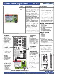
<strong>MC</strong>-6210 Panel <strong>Control</strong> Cards<br />
• The <strong>MC</strong>-6210 panel control card operates<br />
slave cards <strong>MC</strong>-6416 Relay Output<br />
Card(s) and <strong>MC</strong>-6308 Input Card(s).<br />
Connect slave cards to the <strong>MC</strong>-6210 card<br />
with the panel bus. Each slave card has a<br />
card# that identifies it to the <strong>MC</strong>-6210.<br />
<strong>MC</strong>-6210-A Stand Alone Model<br />
• The <strong>MC</strong>-6210-A panel control card is a<br />
stand-alone card designed to be<br />
programmed with the KB-3031 keypad<br />
that plugs into the "Handheld Keypad"<br />
receptacle on this card.<br />
• The <strong>MC</strong>-6210-A cannot be networked to<br />
other <strong>MC</strong>-6210-A cards.<br />
<strong>MC</strong>-6210-N Network Model<br />
• The <strong>MC</strong>-6210-N panel control card is a<br />
networkable card that can be attached to<br />
other cards and ultimately to a PC. The<br />
PC is only required to program the card.<br />
During running mode, the card operates<br />
without the need of the PC.<br />
All ON & OFF<br />
• The All ON & All OFF buttons to<br />
the right switch all of the relays<br />
connected to Output cards<br />
attached to this card.<br />
• The All ON & All OFF buttons on<br />
the individual <strong>MC</strong>-6416 Relay<br />
Output cards switch relays<br />
attached to that card only.<br />
<strong>Data</strong><br />
Signal<br />
Activity<br />
All<br />
ON<br />
All<br />
OFF<br />
Card Power White<br />
(24 vac) Blue<br />
lighting controls<br />
Handheld<br />
Keypad KB-3031<br />
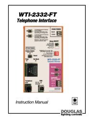
DESCRIPTION<br />
<br />
The <strong>MC</strong>-<strong>6000</strong> System is a full featured<br />
lighting control system that can be<br />
networked to include relay panels,<br />
dimming panels, and PC computers.<br />
<br />
The <strong>MC</strong>-<strong>6000</strong> System is typically used<br />
for complex or larger scale projects. It is<br />
ideal for office towers, shopping<br />
centers, stadiums, and institutional<br />
buildings.<br />
<br />
Each relay panel is equipped with an<br />
<strong>MC</strong>-<strong>6000</strong> interface unit. The unit<br />
contains all of the programs and<br />
functions assigned to it in its on-board<br />
memory. This ensures speedy response<br />
to user inputs.<br />
<br />
The <strong>MC</strong>-<strong>6000</strong> interface units installed in<br />
each of the panels are networked<br />
together with a 2-wire data signal. A PC<br />
connected to the data signal is used to<br />
program the system, retrieve logging<br />
information and to manually switch and<br />
monitor any relay or groups of relays in<br />
the system.<br />
<br />
An <strong>MC</strong>-<strong>6000</strong> interface unit can also be<br />
used in the stand alone <strong>MC</strong>-<strong>6000</strong>A<br />
format. Programming is accomplished<br />
with the hand held unit KB-3031.<br />
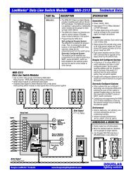
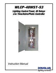
<strong>MC</strong>-<strong>6000</strong> Panel Interface Units<br />
<strong>MC</strong>-<strong>6000</strong> interface assemblies consist of a CPU unit that has Input and Output<br />
modules plugged into it. <strong>MC</strong>-<strong>6000</strong> interface assemblies are networked to form a<br />
building wide lighting control system. Programming and monitoring is done with a PC.<br />
Reset Button<br />
Reset button for re-booting interface.<br />
System Address Setting<br />
Each <strong>MC</strong>-6210 CPU has a unique<br />
address that identifies it to the<br />
lighting control system. Up to 249<br />
<strong>MC</strong>-6210 units can exist in a network.<br />
<strong>Data</strong> Signal<br />
The <strong>MC</strong>-<strong>6000</strong> system uses an RS-485<br />
data signal. Wire is a twisted, sheilded<br />
pair with a ground wire.<br />
Twisted pair<br />
Ground wire<br />
White<br />
Blue<br />
<strong>MC</strong>-6416<br />
Output Module<br />
Relay Power<br />
(24 vac)<br />
<strong>MC</strong>-6308<br />
Input Module<br />
<strong>MC</strong>-6210<br />
CPU Module<br />
Relay Outputs<br />
16 relay outputs (8 per side)<br />
that operate Douglas<br />
2-wire relays.<br />
On-board Overrides<br />
ON and OFF scan buttons<br />
provide All ON and All OFF<br />
override control of relays<br />
connected to the module.<br />
Inputs<br />
8 switch inputs compatible<br />
with Douglas relay switches<br />
or with contact closures.<br />
Address Switch<br />
(also on <strong>MC</strong>-6416 unit)<br />
Each module has an address<br />
switch that uniquely identifies it<br />
to the <strong>MC</strong>-6210 CPU card.<br />
Brief System Description<br />
A brief description of the system<br />
exists on the label to familiarize<br />
service personnel with the basic<br />
function of the <strong>MC</strong>-<strong>6000</strong> unit.<br />
24VAC Power<br />
Connections for 24VAC Power.<br />
<strong>MC</strong>-<strong>6000</strong>A Option<br />
The <strong>MC</strong>-<strong>6000</strong> interface unit can<br />
be used in a stand-alone format.<br />
Plug the KB-3031 hand unit into<br />
this connector.<br />
www.Douglas<strong>Lighting</strong><strong>Control</strong>s.com<br />
SPECIFICATION<br />
Inputs & Outputs<br />
<br />
Modular construction. Input and Output<br />
units plug into the host CPU unit to form<br />
an <strong>MC</strong>-<strong>6000</strong> interface unit.<br />
<br />
The <strong>MC</strong>-6210 CPU can host up to 8<br />
<strong>MC</strong>-6308 Switch Input units (64 inputs<br />
total) and 4 <strong>MC</strong>-6416 Relay Output<br />
units (64 outputs total).<br />
<br />
An <strong>MC</strong>-6308 Input unit has 8 inputs<br />
compatible with Douglas relay switches<br />
or momentary/maintained contacts.<br />
<br />
An <strong>MC</strong>-6416 Output unit has 16 outputs<br />
compatible with all models of Douglas<br />
2-wire relay.<br />
<br />
<strong>MC</strong>-<strong>6000</strong> interface units are networked<br />
with a 2-wire, RS-485 signal. Up to 249<br />
interface units can exist in a network.<br />
Programming <strong>Control</strong>s<br />
<br />
Programming the lighting control<br />
system is done with a remote PC<br />
connected to system's data signal. The<br />
<strong>MC</strong>-<strong>6000</strong> system software runs on<br />
Windows 95/98, NT, Win2000 or XP<br />
operating systems.<br />
<br />
Software features include:<br />
- relay group assignments<br />
- weekly & holiday time schedules<br />
- switch input & time schedule functions<br />
- switch configuration options include<br />
on/off, flick-warn, time-out, delay-off<br />
and priority masking. Options are<br />
viewed and set with the PC software.<br />
<br />
Central software graphic manual<br />
override available with the central<br />
software modules.<br />
<br />
All programs (except building graphic)<br />
are resident in the <strong>MC</strong>-<strong>6000</strong> panel<br />
interfaces, not the PC. Relay panels<br />
function even when the PC is off-line.<br />
<br />
Programming is not lost when power is<br />
turned off to an <strong>MC</strong>-<strong>6000</strong> interface.<br />
<br />
Memory capacity for definitions for each<br />
<strong>MC</strong>-<strong>6000</strong> interface are:<br />
- Individual adjustment for each input<br />
and/or schedule (Flick-warn: 0-99min,<br />
Time-out: 0-999min, Delay-off: 0-99).<br />
- 128 input programs<br />
- 128 holidays<br />
- Date/Time<br />
- Date: YY-MM-DD<br />
- Time: HH-MM (24 hour format)<br />
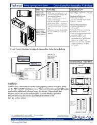
DIMENSIONS & MOUNTING<br />
<br />
Each <strong>MC</strong>-<strong>6000</strong><br />
interface consists of a<br />
CPU unit, input and<br />
output modules.<br />
<br />
The interfaces are<br />
installed in between<br />
the 2 rows of relays in<br />
the panel on a 35mm<br />
DIN rail.<br />
4.0"<br />
(102)<br />
Output<br />
<strong>MC</strong>-6416<br />
Input<br />
<strong>MC</strong>-6308<br />
CPU<br />
<strong>MC</strong>-6210<br />
3.5"<br />
(89)<br />
3.5"<br />
(89)<br />
6.5"<br />
(165)
<strong>MC</strong>-<strong>6000</strong> <strong>Networked</strong> <strong>Lighting</strong> <strong>Control</strong><br />
<strong>MC</strong>-<strong>6000</strong><br />
<strong>Technical</strong> <strong>Data</strong><br />
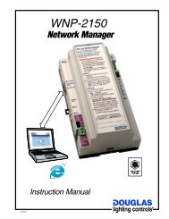
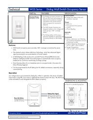
Office Floor - Reflected Ceiling Plan<br />
Office<br />
Office Office Office<br />
Sw<br />
Office<br />
Sw<br />
Office<br />
Sw<br />
Sw<br />
N.W.<br />
Quadrant<br />
BBE? A<br />
Stores<br />
0 = <br />
Sw<br />
A I<br />
Sw<br />
E> H= HO<br />
+ 4 -<br />
Office Office Office<br />
Sw<br />
Sw<br />
5 M<br />
2 D J ? F O<br />
Sw<br />
2 HE JA HI<br />
Local<br />
Switches<br />
Connect direct<br />
to the relay<br />
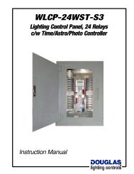
CONNECTIONS<br />
Individual, Master and Central <strong>Control</strong><br />
To switch only an individual relay, connect the Douglas wall switch<br />
directly to the relay. Response is instant, wiring is simple and no<br />
programming required.<br />
Master control of several relays is accomplished by connecting<br />
the Douglas wall switch to an input of the <strong>MC</strong>-6308. Program the<br />
input to switch any relay or group of relays in the system.<br />
Other devices such as key switches, photosensors and contacts<br />
from other devices or systems can also be connected to an <strong>MC</strong>-<br />
6308 input to actuate a relay or group of relays (not shown).<br />
The outputs of the <strong>MC</strong>-6416 control and monitor the state of the<br />
relay connected to an output. The <strong>MC</strong>-6210 holds the programs<br />
and provides the link to the rest of the lighting control system.<br />
9 D EJA<br />
Relay Panel<br />
Relay<br />
Group<br />
1<br />
<strong>Lighting</strong> Circuit<br />
NW Priv Office<br />
Transformer<br />
24VAC<br />
W<br />
B<br />
Relays<br />
Transformer<br />
W 24VAC<br />
B<br />
Relays<br />
H<br />
Breaker<br />
Lights<br />
1<br />
NW Priv Office<br />
1<br />
Library<br />
1<br />
Library<br />
1<br />
NW Priv Office<br />
1<br />
NW Priv Office<br />
1<br />
5<br />
5<br />
NW Priv Office<br />
Hall<br />
Hall<br />
1<br />
2<br />
3<br />
4<br />
5<br />
6<br />
7<br />
8<br />
W<br />
B<br />
Panel<br />
Bus<br />
<strong>MC</strong>-6416<br />
Output<br />
Panel<br />
Bus<br />
Unit<br />
Address<br />
1, 2, 3 or 4<br />
9<br />
10<br />
11<br />
12<br />
13<br />
14<br />
15<br />
16<br />
Wh<br />
Bu<br />
5<br />
5<br />
5<br />
Elevator Lobby<br />
Mens WC<br />
Ladies WC<br />
1<br />
2<br />
3<br />
4<br />
5<br />
6<br />
7<br />
8<br />
W<br />
B<br />
Panel<br />
Bus<br />
<strong>MC</strong>-6416<br />
Output<br />
Panel<br />
Bus<br />
Panel<br />
Bus<br />
Panel<br />
Bus<br />
Unit<br />
Address<br />
1, 2, 3 or 4<br />
<strong>MC</strong>-6308<br />
Input<br />
9<br />
10<br />
11<br />
12<br />
13<br />
14<br />
15<br />
16<br />
Wh<br />
Bu<br />
1<br />
2<br />
3<br />
4<br />
Bu<br />
5678<br />
Bu<br />
Wh<br />
Bu<br />
Unit Address<br />
1,2,3,4,5,6,7or8<br />
Master Switch Station<br />
NW<br />
Quad<br />
SW<br />
Quad<br />
NE<br />
Quad<br />
SE<br />
Quad<br />
NE<br />
Quad<br />
SE<br />
Quad<br />
Panel<br />
Bus<br />
Core<br />
& Hall<br />
Core<br />
& Hall<br />
System<br />
Address<br />
(1 to 255)<br />
<strong>MC</strong>-6210<br />
CPU<br />
W<br />
24VAC<br />
Power<br />
<strong>Data</strong> Signal<br />
-RS-485 Signal<br />
-Twisted, sheilded pair conductors<br />
and ground wire<br />
Twisted pair<br />
Ground wire<br />
<strong>Data</strong><br />
Signal<br />
Unit<br />
Power<br />
Wh<br />
Bu<br />
Interfaces 5.2<br />
C-5-1,2,3,4 -<strong>MC</strong>-<strong>6000</strong> System<br />
www.Douglas<strong>Lighting</strong><strong>Control</strong>s.com
<strong>MC</strong>-<strong>6000</strong> <strong>Networked</strong> <strong>Lighting</strong> <strong>Control</strong><br />
<strong>MC</strong>-<strong>6000</strong><br />
<strong>Technical</strong> <strong>Data</strong><br />
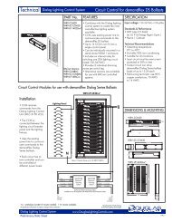
CONNECTIONS & PROGRAMMING<br />
Typical Scheduling<br />
Scheduled switching of lighting circuits will yield significant energy<br />
savings. A common application is to schedule periodic OFF<br />
signals during unoccupied hours to ensure lights are OFF.<br />
Install wall switches to provide for occupant override. This can be<br />
either individual switches connected directly to the relays and/or<br />
master switches connected to the <strong>MC</strong>-<strong>6000</strong> interface.<br />
Program periodic OFF signals (typically 2 hours) during<br />
unoccupied hours. The interface can be set to provide a "Flickwarn<br />
before OFF" prior to executing an off schedule.<br />
Programming ON signals is optional; better energy savings result<br />
if lights are turned ON manually by wall switch(es).<br />
Schedules have a variety of features that can be applied to suit<br />
any situation. Schedules can be set to be only operational for<br />
certain times of the year (eg: XMas shopping hours), can be set to<br />
disable switches for certain time periods during the day (prevents<br />
nuisance switching) and can be set to occur at different times on<br />
different days.<br />
Master Switch Inputs<br />
The input is configured to be compatible with the device<br />
connected to it. The default configuration is a Douglas 2-Wire<br />
relay switch. To change the configuration of the input use the<br />
software on the PC to access the input and select a different<br />
option. Configuration options available are:<br />
1) Douglas Relay Switch (ON & OFF)<br />
2) Douglas Relay Switch (OFF & ON)<br />
3) 24V Contact*: ON signal on closure, OFF signal on opening<br />
4) 24V Contact*: ON signal on closure, NOTHING on opening<br />
5) 24V Contact*: NOTHING on closure, OFF signal on opening<br />
6) 24V Contact*: OFF signal on closure, ON signal on opening<br />
7) 24V Contact*: OFF signal on closure, NOTHING on opening<br />
8) 24V Contact*: NOTHING on closure, ON on opening<br />
* 24V Contact is a dry contact that passes a 24VAC signal.<br />
With the PC computer, define a group of relays and assign that<br />
group a name. Then for the switch input, assign the relay group<br />
name to respond to that input. You can also assign the same relay<br />
group name to a schedule to automate the relay group.<br />
PC Interface<br />
The actual software that runs the lighting control system resides in<br />
the <strong>MC</strong>-6210 CPU Modules that are installed in the relay panels.<br />
The <strong>MC</strong>-6210 Modules run independently and do not require that<br />
a PC is connected to the system.<br />
The PC user interface permits query and adjustment of programs<br />
resident in the <strong>MC</strong>-6210's. The PC can also be used as a switch<br />
station that displays the true state of the relays and groups and<br />
permits real-time switching of any relay or group of relays in the<br />
system. Standard switching interface is tabular in design and<br />
graphical interfaces are also supported as an option.<br />
Logging and trend analysis of when relays are switched is useful<br />
for re-lamping analysis, power analysis and surveillance of actual<br />
usage of lighting circuits.<br />
Graphical interfaces require initial artwork to be done from the<br />
AutoCad files of the project. Drawings are simplified and rebuilt as<br />
required to form an underlay for lamp symbols and switch icons<br />
imposed on top. The lamps and switches are interactive with the<br />
system and will display the true state of the relays and will switch<br />
in real time by clicking on switch icons. Zoom features permit<br />
drill down to localized areas. Thus there are usually several<br />
graphic screens required for a project.<br />
The <strong>MC</strong>-<strong>6000</strong> software runs on Windows NT, WIndows 2000,<br />
Windows XP, or Windows Vista equipped PCs. To connect to the<br />
system, an RS-485 interface to Comm port or USB port card is<br />
provided (laptop or desktop versions).<br />
PC Interface<br />
<strong>Control</strong> and Programming<br />
Relay Panel<br />
Relay Panel<br />
<strong>MC</strong>-<br />
6210<br />
<strong>MC</strong>-<br />
6210<br />
Interfaces 5.3<br />
C-5-1,2,3,4 -<strong>MC</strong>-<strong>6000</strong> System<br />
www.Douglas<strong>Lighting</strong><strong>Control</strong>s.com
<strong>MC</strong>-<strong>6000</strong> <strong>Networked</strong> <strong>Lighting</strong> <strong>Control</strong><br />
<strong>MC</strong>-<strong>6000</strong><br />
<strong>Technical</strong> <strong>Data</strong><br />
<strong>MC</strong>-<strong>6000</strong> SYSTEM FEATURES<br />
Standard Hardware Features<br />
Desktop PC and/or Laptop operator's terminal<br />
True relay status (monitoring of each relay coil)<br />
Local/master low voltage switch capability<br />
Pre-wired relays and programmable inputs<br />
Battery backed up memory / time clock<br />
UL listed / CSA approved<br />
Standard Software Features<br />
Operates on Windows 95/98, NT, Win2000 or XP Systems<br />
Time event scheduling<br />
Manual override control (masking, ON/OFF and flick)<br />
Holiday and special day scheduling<br />
Occupancy warning (remote supervision)<br />
Power usage logging<br />
Peak demand monitoring<br />
Total energy consumption record<br />
Tenant billing<br />
Lamping<br />
Optional Features<br />
Laptop operator's terminal<br />
Custom graphics for manual control<br />
Telephone override<br />
Event printer<br />
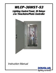
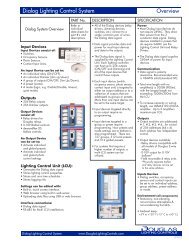
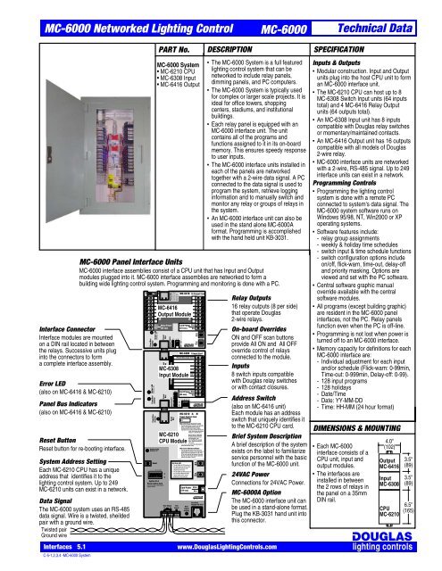
INSTALLATION<br />
The Douglas relays are factory installed and pre-wired to the <strong>MC</strong>-<br />
<strong>6000</strong> interface outputs in the relay panel. To network the panels,<br />
run the the 2 wire data signal in a serial line from panel to panel.<br />
The data signal is standard RS-485 signal that requires a twisted<br />
#20 AWG wire pair in a cable with a foil shield.<br />
Connect standard Douglas 2-wire switches direct to relays to<br />
operate individual lighting relays. Connect Douglas 2-wire<br />
switches to contact inputs to operate relay groups. Use #18 AWG<br />
solid conductor for switch connections.<br />
Install switches at convenient locations and program master<br />
switches and schedules as required with the PC.<br />
Optional telephone interface permits occupants to switch lights via<br />
telephone. User dials in and enters passcode to switch lights.<br />
PC<br />
Computer<br />
2<br />
2<br />
Typical One-line Diagram of <strong>MC</strong>-<strong>6000</strong> System<br />
1 st Floor<br />
<strong>Lighting</strong><br />
<strong>Control</strong><br />
Panel<br />
LC-001<br />
30 th Floor<br />
<strong>Lighting</strong><br />
<strong>Control</strong><br />
Panel<br />
LC-030<br />
<strong>MC</strong>-<strong>6000</strong><br />
Floors<br />
5 to 29<br />
4 th Floor<br />
<strong>Lighting</strong><br />
<strong>Control</strong><br />
Panel<br />
LC-004<br />
<strong>MC</strong>-<strong>6000</strong><br />
3 rd Floor<br />
<strong>Lighting</strong><br />
<strong>Control</strong><br />
Panel<br />
LC-003<br />
<strong>MC</strong>-<strong>6000</strong><br />
2 nd Floor<br />
<strong>Lighting</strong><br />
<strong>Control</strong><br />
Panel<br />
LC-002<br />
<strong>MC</strong>-<strong>6000</strong><br />
2<br />
4<br />
3<br />
2<br />
2<br />
Exterior<br />
Photocell<br />
Interior<br />
Photocell<br />
Occupancy<br />
Detector<br />
1 device Local<br />
Switch Station<br />
Time-out Switch<br />
12 Master Switch Station<br />
<strong>MC</strong>-<strong>6000</strong><br />
13<br />
2<br />
2<br />
Optional<br />
Telephone<br />
Interface<br />
Interfaces 5.4<br />
C-5-1,2,3,4 -<strong>MC</strong>-<strong>6000</strong> System<br />
www.Douglas<strong>Lighting</strong><strong>Control</strong>s.com