Proper Testing of Protection Systems Ensures Against ... - CacheFly
Proper Testing of Protection Systems Ensures Against ... - CacheFly
Proper Testing of Protection Systems Ensures Against ... - CacheFly
- No tags were found...

Create successful ePaper yourself
Turn your PDF publications into a flip-book with our unique Google optimized e-Paper software.
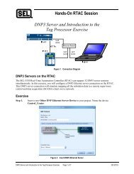
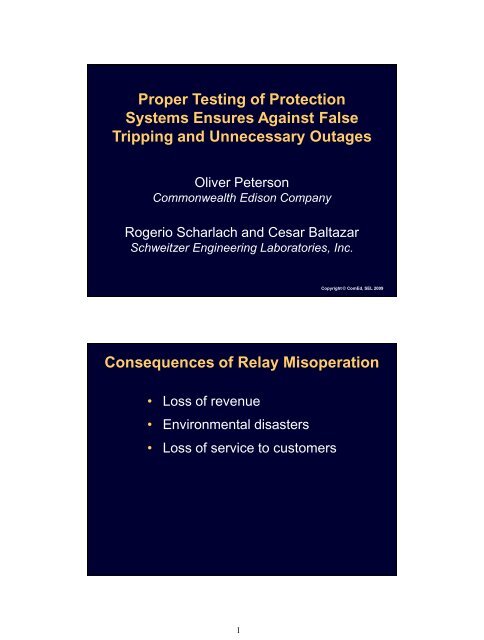
<strong>Proper</strong> <strong>Testing</strong> <strong>of</strong> <strong>Protection</strong><br />
<strong>Systems</strong> <strong>Ensures</strong> <strong>Against</strong> False<br />
Tripping and Unnecessary Outages<br />
Oliver Peterson<br />
Commonwealth Edison Company<br />
Rogerio Scharlach and Cesar Baltazar<br />
Schweitzer Engineering Laboratories, Inc.<br />
Copyright © ComEd, SEL 2009<br />
Consequences <strong>of</strong> Relay Misoperation<br />
• Loss <strong>of</strong> revenue<br />
• Environmental disasters<br />
• Loss <strong>of</strong> service to customers<br />
1
Possible Causes <strong>of</strong> Relay Misoperation<br />
• Incorrect CT ratio<br />
• Incorrect primary polarity orientation<br />
• Incorrect wiring<br />
• Incorrect relay settings<br />
• Poor CT performance<br />
Commissioning Activities<br />
• CT testing<br />
Ratio, polarity, and saturation<br />
Dielectric insulation<br />
• Wiring checks<br />
• Relay testing<br />
• Trip checks<br />
• In-service tests<br />
2
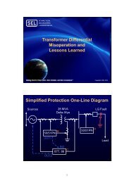
Commissioning<br />
Work Division<br />
87<br />
Three-Phase Primary Injection Benefits<br />
• Test is executed prior to energization<br />
• No load is necessary<br />
• Test can be interrupted at any time<br />
• Test quantities can be calculated<br />
3
Three-Phase Primary Injection Planning<br />
• Safety<br />
• Procedures<br />
• Impact on other protection schemes<br />
• Test equipment<br />
• Calculation <strong>of</strong> test values<br />
Three-Phase Primary Injection Execution<br />
• Personnel – two or more testers required<br />
• Reduced-voltage power supply<br />
Auxiliary station power<br />
Three-phase synchronous generator<br />
4
Three-Phase Primary Injection<br />
Analysis <strong>of</strong> Results<br />
• Register primary and secondary values<br />
during test<br />
• Interrogate IEDs for available reports<br />
• Compare actual test values with<br />
calculated values<br />
• Analyze any discrepancies and initiate<br />
corrective actions<br />
Case 1:<br />
Delta-Wye Transformer<br />
5
Zone <strong>of</strong><br />
<strong>Protection</strong><br />
H<br />
X<br />
87GD<br />
87<br />
One-Line<br />
Diagram<br />
Through-Fault Test Execution<br />
Three-Phase Test<br />
H<br />
X<br />
Three-Phase Short<br />
Circuit to Ground<br />
Three-Phase,<br />
Reduced-Voltage<br />
Power Supply<br />
6
Through-Fault Test Execution<br />
Single-Phase Test<br />
H<br />
X1<br />
Single-Phase<br />
Short Circuit to<br />
Ground Applied to<br />
X1 Bushing<br />
Three-Phase,<br />
Reduced-Voltage<br />
Power Supply<br />
• Relay reports<br />
Available Results<br />
Measured primary current<br />
Measured differential quantities – operating<br />
and restraint currents<br />
• Test switch measurements – magnitude<br />
and phase angle<br />
7
Analysis <strong>of</strong> Results<br />
• Stable differential element<br />
• CTs set at correct ratio<br />
• Phasing and polarity<br />
• Correct phase rotation<br />
• Correct compensation settings<br />
Case 2:<br />
Bus Section Through-Fault <strong>Testing</strong><br />
8
138 kV Bus<br />
One-Line Diagram<br />
1<br />
2<br />
TR1<br />
CB<br />
12 kV Bus 1<br />
BT 1-2<br />
CB<br />
12 kV Bus 2<br />
5 6<br />
3 7<br />
4<br />
FDR1<br />
CB<br />
8<br />
FDR2<br />
CB<br />
Test Equipment<br />
• Voltage or current source<br />
• Test grounds<br />
• Power meter<br />
9
Three-Phase<br />
Short to Ground<br />
Current<br />
Flow<br />
TR1<br />
TR1<br />
CB<br />
FDR1<br />
CB<br />
12 kV Bus 1<br />
Test Setup<br />
Bus 1 Bus 2<br />
BT 1-2 CB<br />
FDR2<br />
CB<br />
208 Vac Three-Phase Source<br />
Three-Phase<br />
Short to Ground<br />
12 kV Bus 2<br />
Test Setup<br />
Current<br />
Flow<br />
TR1<br />
TR1<br />
CB<br />
FDR1<br />
CB<br />
Bus 1 Bus 2<br />
BT 1-2 CB<br />
FDR2<br />
CB<br />
Current<br />
Flow<br />
208 Vac Three-Phase Source<br />
10
Results<br />
• With known primary current source,<br />
secondary currents can be calculated<br />
• Calculated values are compared to<br />
actual test results<br />
• Phase angle is verified against known<br />
voltage reference and compared to<br />
approved three-line schematic<br />
Questions?<br />
11