INSTALLATION & SERVICING MANUAL BENSON PV TUBULAR CABINET HEATER
DONOTUSE Benson PV Range Mar2011 issue11 - AmbiRad
DONOTUSE Benson PV Range Mar2011 issue11 - AmbiRad
- No tags were found...

You also want an ePaper? Increase the reach of your titles
YUMPU automatically turns print PDFs into web optimized ePapers that Google loves.
installed without the positive connection of<br />
combustion ductwork within a heated space<br />
and where that heated space has a design<br />
air change of less than 0.5 air changes per<br />
hour and that the installer prefers to<br />
mechanically ventilate the heated space<br />
rather than provide ventilation openings then<br />
• The heated space needs to be<br />
mechanically ventilated so that the<br />
design air change is 0.5 air changes<br />
per hour or greater.<br />
• It is a requirement that the mechanical<br />
ventilation shall be of the !input! Type<br />
with either natural or mechanical<br />
extraction.<br />
• Systems of mechanical extraction with<br />
a natural inlet shall not be used.<br />
• It is necessary to provide an automatic<br />
means to safely inhibit heater(s)<br />
operation should mechanical air<br />
supply fail for any reason<br />
2.3.2 Heaters Installed within a Plant<br />
Room or Enclosure.<br />
A plant room means a room housing the<br />
heater plant and probably other items of<br />
building service plant and would generally<br />
have generous space for maintenance.<br />
An enclosure is where the heater is installed<br />
within a compartment or confined area<br />
where space is limited.<br />
Where heaters are installed within a plant<br />
room or enclosure then provision for both<br />
combustion air and / or air for general<br />
ventilation will be required by means of high<br />
and low level ventilation openings (sections<br />
2.3.2.1 and 2.3.2.2 refer to plant room<br />
applications and sections 2.3.2.3 and<br />
2.3.2.4 refer to enclosure applications).<br />
Alternatively the plant room or enclosure<br />
may be mechanically ventilated (section<br />
2.3.2.5 refers)<br />
2.3.2.1 Natural Ventilation Openings<br />
to Plant Rooms for Room Sealed<br />
Heaters<br />
For plant room applications the minimum<br />
free area of ventilation opening will depend<br />
upon whether the heater(s) is installed in<br />
room sealed mode (ie with a positive<br />
connection to atmosphere of both flue and<br />
combustion air).<br />
Or with flue only (ie without the positive<br />
connection to atmosphere of a combustion<br />
air duct)<br />
Where the heater(s) is installed in a plant<br />
room and in room sealed mode (ie with a<br />
positive connection to atmosphere of both<br />
flue and combustion air ) the minimum free<br />
area of ventilation opening needs to be<br />
• At high level 5 cm 2 for each kW of<br />
rated heat input.<br />
• At low level 5 cm 2 for each kW of rated<br />
heat input<br />
The high level ventilation opening should be<br />
sited on an external wall and positioned as<br />
high as is practical and always within the top<br />
15% of the wall height.<br />
The low level natural ventilation opening<br />
should be situated on an external wall and<br />
be within 1000 mm of floor level for natural<br />
gas and ideally at floor level for l.p.g gas<br />
installations but in any event no higher than<br />
250 mm.<br />
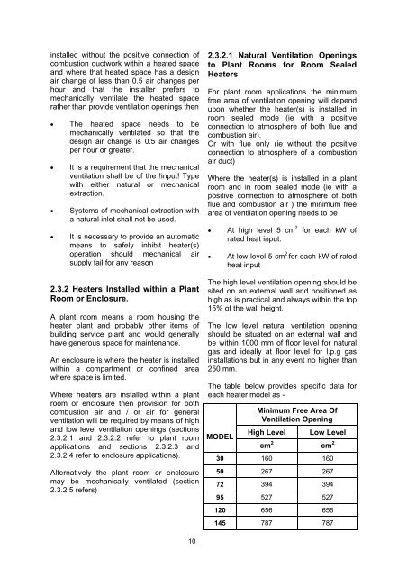
The table below provides specific data for<br />
each heater model as -<br />
MODEL<br />
Minimum Free Area Of<br />
Ventilation Opening<br />
High Level<br />
Low Level<br />
cm 2 cm 2<br />
30 160 160<br />
50 267 267<br />
72 394 394<br />
95 527 527<br />
120 656 656<br />
145 787 787<br />
10