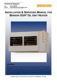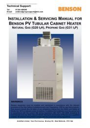
INSTALLATION & SERVICING MANUAL BENSON PV TUBULAR CABINET HEATER
DONOTUSE Benson PV Range Mar2011 issue11 - AmbiRad
DONOTUSE Benson PV Range Mar2011 issue11 - AmbiRad
- No tags were found...

Create successful ePaper yourself
Turn your PDF publications into a flip-book with our unique Google optimized e-Paper software.
cover plate and disconnect the cables.<br />
Remove the screws which secure the unit to<br />
the side of the heater and withdraw the<br />
thermostat complete from the heater.<br />
Check that the bi metal coil and its housing<br />
are secure clean as necessary with a soft<br />
brush.<br />
Flue System<br />
Check that the flue is in good condition, that<br />
it is adequately supported, that there are no<br />
blockages or restrictions.<br />
Check that any joints are properly sealed<br />
preventing an escape of products of<br />
combustion.<br />
Check condensate drain if fitted .<br />
Check for signs of water ingress and any<br />
resultant damage.<br />
Flue Venter<br />
Check that the flue fan is clean and free<br />
from any dust deposits<br />
Differential Air Pressure Switch<br />
Check that the tubes are connected and<br />
clear and free from dust.<br />
Check that they are not kinked or damaged.<br />
Check electrical connections are intact.<br />
Fan and Motor complete<br />
Check that the fan is secure and rotates<br />
freely without excessive play in the shaft.<br />
The fan blades and motor should be<br />
cleaned using a soft brush.<br />
Check that the bearings do not show signs<br />
of excessive wear.<br />
It should be noted that these bearings do<br />
not require lubricating.<br />
Main Fan Motor<br />
Remove access panel. Dust and other<br />
foreign matter should be cleaned by blowing<br />
over with compressed air and through the<br />
use of a soft bristle brush and cloth. Solvent<br />
wipes may be used to remove heavy soiling<br />
from the motor casing.<br />
The electrical connections should be<br />
checked as follows.<br />
The cover to the terminal box should be<br />
removed by undoing the screws, which<br />
secure it.<br />
Check connections for signs of corrosion,<br />
tightness, and ensure that there are no stray<br />
strands which could form a short circuit.<br />
Clean, tighten, and replace as necessary.<br />
Replace cover and secure.<br />
Main Fan<br />
Remove dust and other foreign matter by<br />
blowing off with compressed air or through<br />
the use of a soft bristle brush. Check that<br />
the bearings do not show signs of excessive<br />
wear.<br />
It should be noted that these are sealed<br />
bearings if they are worn the whole fan<br />
assembly will require replacement the<br />
following procedure should be carried out.<br />
(a) Release the tension on the belt(s) and<br />
remove.<br />
(b) Unbolt and remove fan from heater<br />
(c) Remove taperlock and pulley<br />
(d) Fit taperlock and pulley to new fan<br />
(e) Refit fan into heater and bolt in place .<br />
(f) Refit the belts.<br />
(g) Turn by hand to ensure free fan rotation.<br />
Pulleys<br />
Check pulleys for alignment using a straight<br />
edge, if necessary reposition either or both<br />
of the pulleys and the fan motor.<br />
Check for excessive wear within the root<br />
and sides of the grooves, and check for any<br />
other signs of wear or damage, if necessary<br />
replace the pulley as follows.<br />
(a) Release tension on belts and remove.<br />
(b) Release the taper locks by slackening<br />
the securing screws by several complete<br />
turns.<br />
24