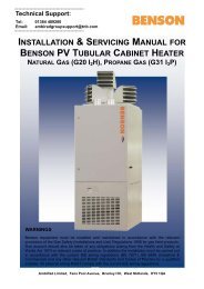
INSTALLATION & SERVICING MANUAL BENSON PV TUBULAR CABINET HEATER
DONOTUSE Benson PV Range Mar2011 issue11 - AmbiRad
DONOTUSE Benson PV Range Mar2011 issue11 - AmbiRad
- No tags were found...
Create successful ePaper yourself
Turn your PDF publications into a flip-book with our unique Google optimized e-Paper software.
2.4 Flue Installation.<br />
An integral flue spigot is fitted to all <strong>PV</strong> Air<br />
Heaters thereby allowing the flue to connect<br />
directly to the heater.<br />
The design of the flue must ensure that it<br />
can be disconnected to allow for cleaning<br />
and servicing. All joints should be sealed<br />
between the sections.<br />
Warning On <strong>PV</strong>72 to 145 a Combustion<br />
Air Plate is supplied as standard this<br />
MUST be fitted in place of the<br />
combustion air spigot if the heater is to<br />
be installed in the flue only option.<br />
It is essential that the products of<br />
combustion are flued to the outside of the<br />
building.<br />
Each heater must have its own separate<br />
flue, with a flue diameter of not less than is<br />
detailed in section 7.2 within this manual.<br />
The flue assembly must comply with all the<br />
relevant regulations regarding height and<br />
materials, and must terminate with an<br />
approved flue terminal.<br />
Care should be taken to ensure that the flue<br />
terminal is not situated in a high pressure<br />
area, the proximity of buildings and other<br />
obstacles which will influence this must be<br />
taken into account, preferably at the design<br />
stage.<br />
All <strong>PV</strong> Heaters are equipped with a built in<br />
flue venter fan which prevents the<br />
re circulation of combustion products,<br />
consequently an external draught diverter,<br />
barometric damper, or anti spillage system<br />
must not be installed. Such devices are<br />
unnecessary on the <strong>PV</strong> range of heaters.<br />
Horizontal flue installations must not<br />
exceed those stated in the following<br />
pages<br />
Each 90 0 bend corresponds to 1Mtr of flue<br />
length<br />
Each 45 0 bend corresponds to 0.8 Mtr of<br />
flue length<br />
In order to provide adequate natural<br />
draught, the minimum length of horizontal<br />
flue must not be less than 1m.<br />
For vertical flue installations the flue should<br />
rise vertically where possible bends should<br />
not exceed 45 0 and the number of bends<br />
should be kept to a minimum.<br />
Maximum vertical flue length must not<br />
exceed that stated in the following pages.<br />
The temperature of the combustion products<br />
can be as high as 170 0 C and therefore tend<br />
to rise naturally within the flue. Unnecessary<br />
bends and restrictions should therefore be<br />
avoided.<br />
Caution<br />
It is imperative that the flue should be<br />
properly sealed where it passes through the<br />
roof, this can best be achieved by using the<br />
approved method of roof flashing plate and<br />
cravat. The flue spigot outlet on all <strong>PV</strong><br />
heaters is in vertical configuration.<br />
Note<br />
It should be noted that claims made under<br />
warranty and attributed to the ingress of<br />
water may not be considered especially if an<br />
approved method of sealing has not been<br />
used, or if the design of the flue has not<br />
made provision for possible condensation<br />
problems.<br />
It is also recommended that BS5854: 1980<br />
and BS5440: parts 1 and 2 are used as a<br />
consultative document when considering<br />
flue requirements.<br />
If terminating through a wall only use<br />
approved horizontal terminals<br />
Provision for the disconnection of the flue for<br />
servicing and inspection purposes must also<br />
be made.<br />
The position of the flue and its terminal<br />
should be such that it does not impair the<br />
combustion process. It should terminate in<br />
an exposed position so as to allow the free<br />
escape of flue gases without risk of their reentering<br />
the building through windows,<br />
ventilation ports etc.<br />
13


