Bul. 440R — Guardmaster® Safety Relays (DI, DIS, and EM ...
Bul. 440R — Guardmaster® Safety Relays (DI, DIS, and EM ...
Bul. 440R — Guardmaster® Safety Relays (DI, DIS, and EM ...

You also want an ePaper? Increase the reach of your titles
YUMPU automatically turns print PDFs into web optimized ePapers that Google loves.
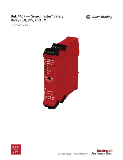
<strong>Bul</strong>. <strong>440R</strong> <strong>—</strong> <strong>Guardmaster®</strong> <strong>Safety</strong><br />
<strong>Relays</strong> (<strong>DI</strong>, <strong>DI</strong>S, <strong>and</strong> <strong>EM</strong>)<br />
Selection Guide
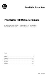
<strong>Bul</strong>letin <strong>440R</strong><br />
Next Generation <strong>Guardmaster®</strong> <strong>Safety</strong> <strong>Relays</strong><br />
<strong>DI</strong>, <strong>DI</strong>S, <strong>and</strong> <strong>EM</strong><br />
Description<br />
The new generation of Guardmaster <strong>Safety</strong> <strong>Relays</strong> address the<br />
broad scope of applications in the intricate safety world with a<br />
h<strong>and</strong>ful of devices. Designed to meet new functional safety<br />
st<strong>and</strong>ards, such as EN ISO 13849-1 <strong>and</strong> EN/IEC 62061, the new<br />
family offers key functions to simplify installation <strong>and</strong> system<br />
complexity.<br />
A broad range of safety devices such as safety interlock switches,<br />
E-stop devices, pressure sensitive safety mats, <strong>and</strong> OSSD devices<br />
such as safety light curtains are all compatible with the same relay<br />
without any additional configuration.<br />
The functionality of two st<strong>and</strong>ard safety relays can be achieved in<br />
one Dual Input (<strong>DI</strong>) relay, allowing connection of two dual channel<br />
input devices into one safety relay.<br />
A TÜV approved single rotary switch sets the required function of<br />
the safety relay <strong>and</strong> eliminates typical redundant switch setting.<br />
Selectable functions include simple logic, reset, <strong>and</strong> timing.<br />
The single-wire safety connection simplifies cascading <strong>and</strong><br />
exp<strong>and</strong>ing safety functions by linking relays with a single-wire<br />
connection. A dynamic signal from device to device provides a<br />
linkage in accordance with SIL3, PL e, allowing easy addition of<br />
extra I / O which can be configured with simple logic combinations.<br />
Flexible AND/OR logic can be configured simply in a single relay or<br />
through a combination of relays via single wire connection.<br />
Features<br />
� Suitable for applications up to PLe, Cat. 4 per ISO 13849-1 <strong>and</strong><br />
SIL 3 per EN/IEC 62061<br />
� Stop Category 0<br />
� One or two dual channel inputs<br />
� Two or three safety contacts<br />
� One auxiliary contact<br />
� Cross fault monitoring<br />
� Rotary switch configures auto./manual or monitored manual reset<br />
� Same rotary switch configures AND/OR logic of input to device<br />
� Removable terminals<br />
� Can be used with interlocks, light curtains, safety mats, E-stops,<br />
<strong>and</strong> SensaGuards<br />
� Single-wire safety output connects to single-wire safety input<br />
relays while maintainging SIL 3, PLe<br />
Functional <strong>Safety</strong> Data ✶<br />
Note: For up-to-date information, visit http://www.ab.com/safety/<br />
http://www.ab.com/safety/<br />
PFHD: 9.2 x 10⁻¹⁰h<br />
MTTFd: 631 years<br />
Suitable for performance levels Ple (according to ISO 13849-1:2006)<br />
<strong>and</strong> for use in SIL CL3 systems (according to IEC 62061) depending<br />
on the architecture <strong>and</strong> application characteristics<br />
✶ Usable for ISO 13849-1:2006 <strong>and</strong> IEC 62061. Data is based on the<br />
following assumptions:<br />
- Mission time/Proof test interval of 20 years<br />
- Functional test at least once within six-month period<br />
2<br />
Visit our website: www.ab.com/catalogs<br />
Publication 800B-SG001A-EN-E<br />
Specifications<br />
<strong>Safety</strong> Ratings<br />
EN/IEC 60204-1, ISO 13849-1, EN ISO 12100,<br />
St<strong>and</strong>ards<br />
IEC 61508<br />
<strong>Safety</strong> Classification PLe per ISO 13849-1, SIL CL3 per IEC 61508<br />
CE Marked for all applicable directives, cULus<br />
Certifications<br />
<strong>and</strong> TÜV<br />
Power Supply<br />
Input Power Entry 24V DC (-15…+10%)<br />
Power Consumption<br />
Inputs<br />
<strong>DI</strong>: 2.5 W<br />
<strong>DI</strong>S: 2 W<br />
<strong>EM</strong>: 3.5 W<br />
<strong>DI</strong>/<strong>DI</strong>S: 2 dual N.C. or 2 dual OSSD, <strong>and</strong> 1<br />
<strong>Safety</strong> Inputs<br />
single-wire safety input<br />
<strong>EM</strong>: 1 single-wire safety input<br />
Input Simultaneity Infinite<br />
Input Resistance, Max. 900 Ω<br />
Reset<br />
Configured automatic/manual or monitored<br />
manual<br />
Reset Pulse Duration 250 ms…3 s<br />
Power ON Delay Time<br />
Recovery Time<br />
Response Time (St<strong>and</strong>ard<br />
<strong>Safety</strong> Outputs)<br />
Response Time (Single-<br />
Wire <strong>Safety</strong> Outputs)<br />
<strong>DI</strong>/<strong>DI</strong>S: 5.5 s<br />
<strong>EM</strong>: 5.5 s<br />
<strong>DI</strong>/<strong>DI</strong>S: 100 ms<br />
<strong>EM</strong>: 150 ms<br />
<strong>DI</strong>: 35 ms (40 ms with mat input)<br />
<strong>DI</strong>S: 25 ms (30 ms with mat input)<br />
<strong>EM</strong>: 35 ms<br />
<strong>DI</strong>: 25 ms (30 ms with mat input)<br />
<strong>DI</strong>S: 25 ms (30 ms with mat input)<br />
<strong>EM</strong>: 25 ms<br />
Outputs<br />
<strong>Safety</strong> Contacts<br />
<strong>DI</strong>: 2 N.O.<br />
<strong>DI</strong>S: 2 PNP<br />
<strong>EM</strong>: 4 N.O.<br />
Contact Material<br />
<strong>DI</strong>: AgNi + .2μ Au<br />
<strong>EM</strong>: AgNi<br />
Auxiliary Contacts<br />
<strong>DI</strong>/<strong>DI</strong>S: 1 PNP; 50 mA max<br />
<strong>EM</strong>: 1 PNP; 50 mA max<br />
Thermal CurrentIlth <strong>DI</strong>: 1 x 6 A<br />
<strong>EM</strong>: 1 x 8 A<br />
Rated Impulse withst<strong>and</strong><br />
Voltage<br />
2500V<br />
Switching Current @<br />
Voltage, Min.<br />
<strong>DI</strong>/<strong>EM</strong>: 10 mA/10V<br />
Fuses, Output 6 A slow blow or 10 A quick blow<br />
Mechanical Life<br />
Utilization Category<br />
<strong>DI</strong>/<strong>EM</strong>: 10,000,000 operations<br />
Inductive: AC-15<br />
Inductive: DC-13<br />
<strong>DI</strong>: 3 A/250V AC<br />
<strong>EM</strong>: 1.5 A/250V AC<br />
<strong>DI</strong>: 4 A/24V DC (0.1 Hz)<br />
<strong>EM</strong>: 2 A/24V DC<br />
Output Rating<br />
<strong>DI</strong>S: 14, 24: 1.5 A each<br />
34, 44: 0.5 A each<br />
Environmental <strong>and</strong> Physical Characteristics<br />
Enclosure Type Rating/<br />
Terminal Protection<br />
IP40 (N<strong>EM</strong>A 1)/IP20<br />
Operating Temperature<br />
[C (F)]<br />
-5…+55 ° (23…131 °)<br />
Vibration 10…55 Hz, 0.35 mm<br />
Shock 10 g, 16 ms 100 shocks<br />
Mounting 35 mm <strong>DI</strong>N Rail<br />
<strong>DI</strong>: 180 (0.40)<br />
Weight [g (lb)]<br />
<strong>DI</strong>S: 150 (0.33)<br />
<strong>EM</strong>: 225 (0.50)<br />
Terminals Removable (Screw)<br />
Conductor Size, Max. 0.2…2.5 mm2 (24…14 AWG)
Product Selection<br />
Dual Input <strong>Relays</strong><br />
<strong>Bul</strong>letin <strong>440R</strong><br />
Next Generation <strong>Guardmaster®</strong> <strong>Safety</strong> <strong>Relays</strong><br />
Visit our website: www.ab.com/catalogs<br />
Publication 800B-SG001A-EN-E<br />
<strong>DI</strong>, <strong>DI</strong>S, <strong>and</strong> <strong>EM</strong><br />
Relay Type No. of Inputs Inputs <strong>Safety</strong> Outputs Auxiliary Outputs Power Supply Cat. No.<br />
Dual Input (<strong>DI</strong>)<br />
1 N.C., 2 N.C., 2 N.O.<br />
<strong>440R</strong>-D22R2<br />
Dual Input Solid-State Output (<strong>DI</strong>S)<br />
2 Dual Channel OSSD, <strong>Safety</strong><br />
Mat<br />
2 S.S.<br />
1 S.S. 24V<br />
<strong>440R</strong>-D22S2<br />
Expansion Module <strong>Relays</strong><br />
Relay Type No. of Inputs <strong>Safety</strong> Outputs Auxiliary Outputs Power Supply Cat. No.<br />
Expansion Module (<strong>EM</strong>)<br />
1 single-wire<br />
safety<br />
4 N.O. 1 S.S. 24V <strong>440R</strong>-<strong>EM</strong>4R2<br />
LED Indicators<br />
Indicator on<br />
Housing Function LED Color(s)<br />
PWR/FAULT Status <strong>and</strong> Diagnostics Green/Red<br />
IN1 Status of safety output IN1 Green<br />
IN2 Status of safety output IN2 Green<br />
LOGIC IN Status of single wire safety input Green<br />
OUT Status of safety output Green<br />
Configuration<br />
The following procedure sets the logic function of the device.<br />
1. Start configuration/overwrite: with power off, turn rotary switch to<br />
position "0" <strong>and</strong> unit is powered up. After power-up test, "PWR"<br />
LED will flash red.<br />
2. Set configuration: turn rotary switch to desired position. IN1 LED<br />
blinks new setting.<br />
Note: Position is not stored until PWR LED is solid green.<br />
3. Lock in configuration by cycling unit power.<br />
4. Configuration must be confirmed before operation. A white<br />
space on face of device is provided to record unit setting.<br />
Enable program mode Set operation mode<br />
Cycle power to store<br />
Accessories<br />
Logic<br />
The logic between the two safety inputs IN1 (S12, S22) <strong>and</strong> IN2<br />
(S32, S42) <strong>and</strong> the single-wire safety input (L12) can be configured<br />
to the four options shown below, in either manual monitored or<br />
automatic/manual reset configurations (yielding eight settings total).<br />
L12 will only recognize a valid test pattern from the L11 output of a<br />
Guardmaster device. Any other signal to that port will be detected<br />
as a fault. (A high signal is considered to be true in this logic. So if<br />
an input is to be ignored or muted, OR logic should be used).<br />
Note: In case only one safety input is used the second one can be<br />
left open if it is configured for OR. An AND conjunction<br />
requires this input to be wired to S11 <strong>and</strong> S21. In case L12 is<br />
not in use, this input needs to be configured for OR.<br />
Manual Monitored Reset<br />
1 (IN1 OR IN2) OR L12<br />
2 (IN1 AND IN2) OR L12<br />
3 (IN1 OR IN2) AND L12<br />
4 (IN1 AND IN2) AND L12<br />
Description Cat. No.<br />
Bag of 4, 4-pin screw terminals <strong>440R</strong>-ATP4<br />
Automatic / Manual Reset<br />
5 (IN1 OR IN2) OR L12<br />
6 (IN1 AND IN2) OR L12<br />
7 (IN1 OR IN2) AND L12<br />
8 (IN1 AND IN2) AND L12<br />
IN1<br />
IN2<br />
L12<br />
AND/<br />
OR<br />
IN1 = S12, S22<br />
IN2 = S32, S42<br />
AND/<br />
OR<br />
3
<strong>Bul</strong>letin <strong>440R</strong><br />
Next Generation <strong>Guardmaster®</strong> <strong>Safety</strong> <strong>Relays</strong><br />
<strong>DI</strong>, <strong>DI</strong>S, <strong>and</strong> <strong>EM</strong><br />
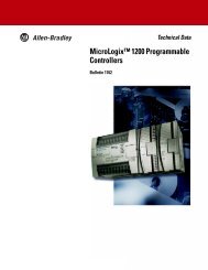
Approximate Dimensions<br />
Dimensions are shown in mm (in.). Dimensions are not intended to be used for installation purposes.<br />
22.5<br />
22.5<br />
(0.88)<br />
4<br />
S12 S22 S32 S42 }X2<br />
A1 A3 S11 S21 }X1<br />
PWR/FAULT<br />
IN1<br />
IN2<br />
LOGIC IN<br />
OUT<br />
L12 L11 Y32 S34<br />
12 14 23 24<br />
<strong>DI</strong><br />
}X3<br />
}X4<br />
119.14<br />
(4.69)<br />
(0.88)<br />
S12 S22 S32 S42 }X2<br />
A1 A2 S11 S21 }X1<br />
PWR/FAULT<br />
IN1<br />
IN2<br />
LOGIC IN<br />
OUT<br />
L12 L11 Y32 S34 }X3<br />
34 44 14 24 }X4<br />
Visit our website: www.ab.com/catalogs<br />
Publication 800B-SG001A-EN-E<br />
22.5<br />
(0.88)<br />
33 34 43 44 }X2<br />
A1 A2 }X1<br />
PWR/FAULT<br />
LOGIC IN<br />
OUT<br />
L12 L11 Y32 }X3<br />
13 14 23 24 }X4<br />
<strong>DI</strong>S <strong>EM</strong><br />
113.6 (4.47)<br />
Side View (<strong>DI</strong>, <strong>DI</strong>S, <strong>and</strong> <strong>EM</strong>)
<strong>Bul</strong>letin <strong>440R</strong><br />
Next Generation <strong>Guardmaster®</strong> <strong>Safety</strong> <strong>Relays</strong><br />
Visit our website: www.ab.com/catalogs<br />
Publication 800B-SG001A-EN-E<br />
<strong>DI</strong>, <strong>DI</strong>S, <strong>and</strong> <strong>EM</strong><br />
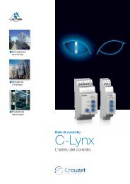
Typical Wiring Diagram<br />
Light Curtain <strong>and</strong> Dual Channel E-stop, Manual Monitored Reset<br />
Here the logic is set to 2 which will AND IN1 <strong>and</strong> IN2. The single wire safety input is set to OR with the st<strong>and</strong>ard safety inputs so the relay<br />
ignores the fact that no input is coming to L12. This logic can be applied to the <strong>DI</strong> <strong>and</strong> <strong>DI</strong>S.<br />
Power<br />
In1<br />
In2<br />
Out<br />
Logic<br />
A2<br />
A1 + -<br />
L12<br />
24V DC<br />
<strong>DI</strong><br />
L11 Y32<br />
S11 S21 S12 S22 S32 S42<br />
PULSE<br />
0<br />
1<br />
IN1<br />
IN2<br />
8<br />
7 6<br />
2<br />
3<br />
4<br />
5<br />
Logic<br />
PLC<br />
Single Channel E-stop, Automatic Reset, Monitoring<br />
Here the logic is set to 5 which will OR all inputs. The device will source its outputs if any input is high. Here S12 <strong>and</strong> S22 are jumpered to<br />
allow for a single-channel source for the one input used.<br />
Power<br />
In1<br />
In2<br />
Out<br />
Logic<br />
E-Stop<br />
K1<br />
OSSD<br />
S34 13 14 23 24<br />
A1 A2<br />
+ -<br />
24V DC<br />
<strong>DI</strong>S<br />
S11 S21<br />
PULSE<br />
0<br />
1<br />
2<br />
3<br />
S12 S22<br />
IN1<br />
S32 S42<br />
IN2<br />
8<br />
7 6<br />
4<br />
5<br />
PULSED<br />
L12 L11 Y32 S34 33 34<br />
14 24<br />
Logic<br />
PLC<br />
E-Stop<br />
K2<br />
K1<br />
K2<br />
Reset<br />
K1<br />
K2<br />
K1<br />
K2<br />
GND<br />
24V DC<br />
L1 L2 L3<br />
M<br />
24V DC<br />
L1 L2 L3<br />
M<br />
GND<br />
5
<strong>Bul</strong>letin <strong>440R</strong><br />
Next Generation <strong>Guardmaster®</strong> <strong>Safety</strong> <strong>Relays</strong><br />
<strong>DI</strong>, <strong>DI</strong>S, <strong>and</strong> <strong>EM</strong><br />
E-stop, <strong>Safety</strong> Mat, Light Curtain <strong>and</strong> Interlock Switch, Monitored Manual Reset<br />
Here the <strong>DI</strong> to the left will AND the IN1 <strong>and</strong> IN2 inputs. The single-wire safety input is ignored. The <strong>DI</strong> on the right will AND IN1, IN2 <strong>and</strong> the<br />
single-wire safety input (L12). For the safety mat input, S11 is wired to S22 <strong>and</strong> S21 is wired to S12 (opposite of st<strong>and</strong>ard switch wiring) so<br />
the relay recognizes that a mat is wired to the input rather than a st<strong>and</strong>ard switch with a cross fault. If the E-stop or the OSSD devices are<br />
tripped all outputs on both relays will turn off. If the mat or interlock switch are tripped only the outputs to K3 <strong>and</strong> K4 will turn off.<br />
Two Dual-Channel E-stops to <strong>DI</strong> Connected to <strong>EM</strong> via Single-Wire <strong>Safety</strong> Connection, Manual Monitored Reset<br />
Here the <strong>DI</strong>S will AND IN1 <strong>and</strong> IN2 while ignoring the single-wire safety input. The single-wire safety output is driving the input of the<br />
expansion module (<strong>EM</strong>) while not using any of the st<strong>and</strong>ard outputs of the base device.<br />
6<br />
Power<br />
In1<br />
In2<br />
Out<br />
Logic<br />
OSSD<br />
A1 A2<br />
+ -<br />
24V DC<br />
<strong>DI</strong><br />
S11 S21<br />
PULSE<br />
Logic 0<br />
1<br />
2<br />
3<br />
8 4<br />
7 6<br />
5<br />
S12 S22<br />
IN1<br />
S32 S42<br />
IN2<br />
L12 L11 Y32 S34 13 14 23 24<br />
A1 A2<br />
+ -<br />
Power<br />
24V DC<br />
In1<br />
<strong>DI</strong>S<br />
In2<br />
Out<br />
Logic<br />
PLC<br />
E-Stop<br />
K1 K2<br />
Reset<br />
S11 S21 S12 S22 S32 S42<br />
IN1<br />
IN2<br />
0<br />
1<br />
A1<br />
LOGIC 2<br />
8<br />
7<br />
6<br />
3<br />
4<br />
5<br />
PLC<br />
Test Out<br />
K1<br />
E-Stop<br />
K2<br />
E-Stop<br />
L12 L11 Y32 S34 33 44 14 24<br />
K1<br />
K2<br />
K3<br />
K4<br />
Power<br />
Logic IN<br />
Out 1<br />
Power<br />
In1<br />
In2<br />
Out<br />
Logic<br />
A2<br />
A1 + -<br />
24V DC<br />
Visit our website: www.ab.com/catalogs<br />
Publication 800B-SG001A-EN-E<br />
<strong>EM</strong><br />
<strong>Safety</strong><br />
Mat<br />
Interlock<br />
A1 A2<br />
+ -<br />
24V DC<br />
<strong>DI</strong><br />
S11 S21<br />
PULSE<br />
Logic 0<br />
1<br />
2<br />
3<br />
8 4<br />
7 6<br />
5<br />
S12 S22<br />
IN1<br />
S32 S42<br />
IN2<br />
L12 L11 Y32 S34 13 14 23 24<br />
33 34 43 44<br />
L12 L11 X32 13 14 23 24<br />
K3 K3<br />
K3 K4<br />
Reset<br />
K1<br />
K2<br />
K3<br />
K4<br />
24V DC<br />
L1 L2 L3<br />
M<br />
GND<br />
24V DC<br />
GND
<strong>Bul</strong>letin <strong>440R</strong><br />
Next Generation <strong>Guardmaster®</strong> <strong>Safety</strong> <strong>Relays</strong><br />
Visit our website: www.ab.com/catalogs<br />
Publication 800B-SG001A-EN-E<br />
Notes<br />
7
Publication 440P-SG001A-EN-P – March 2011 Copyright ©2011 Rockwell Automation, Inc. All Rights Reserved. Printed in USA.