Chapter 8 Lab A Configuring a Site-to-Site VPN Using Cisco IOS and SDM
Chapter 8: Lab A: Configuring a Site-to-Site VPN Using Cisco IOS ...
Chapter 8: Lab A: Configuring a Site-to-Site VPN Using Cisco IOS ...

You also want an ePaper? Increase the reach of your titles
YUMPU automatically turns print PDFs into web optimized ePapers that Google loves.
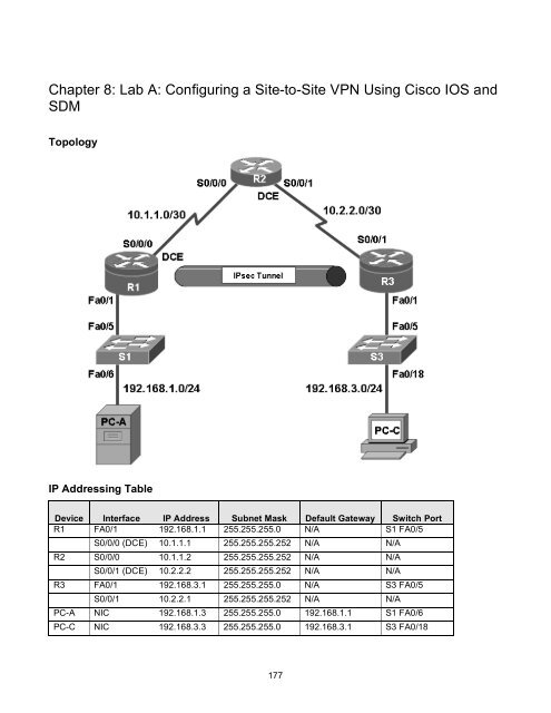
<strong>Chapter</strong> 8: <strong>Lab</strong> A: <strong>Configuring</strong> a <strong>Site</strong>-<strong>to</strong>-<strong>Site</strong> <strong>VPN</strong> <strong>Using</strong> <strong>Cisco</strong> <strong>IOS</strong> <strong>and</strong><br />
<strong>SDM</strong><br />
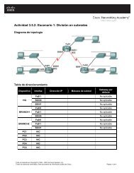
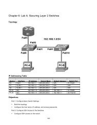
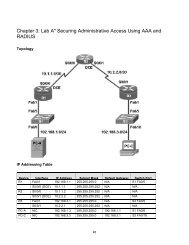
Topology<br />
IP Addressing Table<br />
Device Interface IP Address Subnet Mask Default Gateway Switch Port<br />
R1 FA0/1 192.168.1.1 255.255.255.0 N/A S1 FA0/5<br />
S0/0/0 (DCE) 10.1.1.1 255.255.255.252 N/A N/A<br />
R2 S0/0/0 10.1.1.2 255.255.255.252 N/A N/A<br />
S0/0/1 (DCE) 10.2.2.2 255.255.255.252 N/A N/A<br />
R3 FA0/1 192.168.3.1 255.255.255.0 N/A S3 FA0/5<br />
S0/0/1 10.2.2.1 255.255.255.252 N/A N/A<br />
PC-A NIC 192.168.1.3 255.255.255.0 192.168.1.1 S1 FA0/6<br />
PC-C NIC 192.168.3.3 255.255.255.0 192.168.3.1 S3 FA0/18<br />
177
Objectives<br />
Part 1: Basic Router Configuration<br />
• Configure host names, interface IP addresses, <strong>and</strong> access passwords.<br />
• Configure the EIGRP dynamic routing pro<strong>to</strong>col.<br />
Part 2: Configure a <strong>Site</strong>-<strong>to</strong>-<strong>Site</strong> <strong>VPN</strong> <strong>Using</strong> <strong>Cisco</strong> <strong>IOS</strong><br />
• Configure IPsec <strong>VPN</strong> settings on R1 <strong>and</strong> R3<br />
• Verify site-<strong>to</strong>-site IPsec <strong>VPN</strong> configuration<br />
• Test IPsec <strong>VPN</strong> operation<br />
Part 3: Configure a <strong>Site</strong>-<strong>to</strong>-<strong>Site</strong> <strong>VPN</strong> <strong>Using</strong> <strong>SDM</strong><br />
• Configure IPsec <strong>VPN</strong> settings on R1<br />
• Create a mirror configuration for R3<br />
• Apply the mirror configuration <strong>to</strong> R3<br />
• Verify the configuration<br />
• Test the <strong>VPN</strong> configuration using <strong>SDM</strong><br />
Background<br />
<strong>VPN</strong>s can provide a secure method of transmitting data over a public network, such as the Internet. <strong>VPN</strong><br />
connections can help reduce the costs associated with leased lines. <strong>Site</strong>-<strong>to</strong>-<strong>Site</strong> <strong>VPN</strong>s typically provide a<br />
secure (IPsec or other) tunnel between a branch office <strong>and</strong> a central office. Another common implementation<br />
that uses <strong>VPN</strong> technology is remote access <strong>to</strong> a corporate office from a telecommuter location such as a<br />
small office or home office.<br />
In this lab, you build a multi-router network <strong>and</strong> configure the routers <strong>and</strong> hosts. You use <strong>Cisco</strong> <strong>IOS</strong> <strong>and</strong> <strong>SDM</strong><br />
<strong>to</strong> configure a site-<strong>to</strong>-site IPsec <strong>VPN</strong> <strong>and</strong> test it. The IPsec <strong>VPN</strong> tunnel is from router R1 <strong>to</strong> router R3 via R2.<br />
R2 acts as a pass-through <strong>and</strong> has no knowledge of the <strong>VPN</strong>. IPsec provides secure transmission of<br />
sensitive information over unprotected networks such as the Internet. IPsec acts at the network layer,<br />
protecting <strong>and</strong> authenticating IP packets between participating IPsec devices (peers), such as <strong>Cisco</strong> routers.<br />
Note: The router comm<strong>and</strong>s <strong>and</strong> output in this lab are from a <strong>Cisco</strong> 1841 with <strong>Cisco</strong> <strong>IOS</strong> Release 12.4(20)T<br />
(Advanced IP image). Other routers <strong>and</strong> <strong>Cisco</strong> <strong>IOS</strong> versions can be used. See the Router Interface Summary<br />
table at the end of the lab <strong>to</strong> determine which interface identifiers <strong>to</strong> use based on the equipment in the lab.<br />
Depending on the router model <strong>and</strong> <strong>Cisco</strong> <strong>IOS</strong> version, the comm<strong>and</strong>s available <strong>and</strong> output produced might<br />
vary from what is shown in this lab.<br />
Note: Make sure that the routers <strong>and</strong> the switches have been erased <strong>and</strong> have no startup configurations.<br />
Required Resources<br />
• 3 routers with <strong>SDM</strong> 2.5 installed (<strong>Cisco</strong> 1841 with <strong>Cisco</strong> <strong>IOS</strong> Release 12.4(20)T1 or comparable)<br />
• 2 switches (<strong>Cisco</strong> 2960 or comparable)<br />
• PC-A (Windows XP or Vista)<br />
• PC-C (Windows XP or Vista)<br />
178
• Serial <strong>and</strong> Ethernet cables as shown in the <strong>to</strong>pology<br />
• Rollover cables <strong>to</strong> configure the routers via the console<br />
Part 1. Basic Router Configuration<br />
In Part 1 of this lab, you set up the network <strong>to</strong>pology <strong>and</strong> configure basic settings, such as the interface IP<br />
addresses, dynamic routing, device access, <strong>and</strong> passwords.<br />
Note: All tasks should be performed on routers R1, R2, <strong>and</strong> R3. The procedure for R1 is shown here as an<br />
example.<br />
Step 1: Cable the network as shown in the <strong>to</strong>pology.<br />
Attach the devices shown in the <strong>to</strong>pology diagram, <strong>and</strong> cable as necessary.<br />
Step 2: Configure basic settings for each router.<br />
a. Configure host names as shown in the <strong>to</strong>pology.<br />
b. Configure the interface IP addresses as shown in the IP addressing table.<br />
c. Configure a clock rate for the serial router interfaces with a DCE serial cable attached.<br />
R1(config)#interface S0/0/0<br />
R1(config-if)#clock rate 64000<br />
Step 3: Disable DNS lookup.<br />
To prevent the router from attempting <strong>to</strong> translate incorrectly entered comm<strong>and</strong>s, disable DNS lookup.<br />
R1(config)#no ip domain-lookup<br />
Step 4: Configure the EIGRP routing pro<strong>to</strong>col on R1, R2, <strong>and</strong> R3.<br />
a. On R1, use the following comm<strong>and</strong>s.<br />
R1(config)#router eigrp 101<br />
R1(config-router)#network 192.168.1.0 0.0.0.255<br />
R1(config-router)#network 10.1.1.0 0.0.0.3<br />
R1(config-router)#no au<strong>to</strong>-summary<br />
b. On R2, use the following comm<strong>and</strong>s.<br />
R2(config)#router eigrp 101<br />
R2(config-router)#network 10.1.1.0 0.0.0.3<br />
R2(config-router)#network 10.2.2.0 0.0.0.3<br />
R2(config-router)#no au<strong>to</strong>-summary<br />
c. On R3, use the following comm<strong>and</strong>s.<br />
R3(config)#router eigrp 101<br />
R3(config-router)#network 192.168.3.0 0.0.0.255<br />
R3(config-router)#network 10.2.2.0 0.0.0.3<br />
R3(config-router)#no au<strong>to</strong>-summary<br />
179
Step 5: Configure PC host IP settings.<br />
a. Configure a static IP address, subnet mask, <strong>and</strong> default gateway for PC-A, as shown in the IP<br />
addressing table.<br />
b. Configure a static IP address, subnet mask, <strong>and</strong> default gateway for PC-C, as shown in the IP<br />
addressing table.<br />
Step 6: Verify basic network connectivity.<br />
a. Ping from R1 <strong>to</strong> the R3 Fa0/1 interface at IP address 192.168.3.1.<br />
Were the results successful? _____<br />
If the pings are not successful, troubleshoot the basic device configurations before continuing.<br />
b. Ping from PC-A on the R1 LAN <strong>to</strong> PC-C on the R3 LAN.<br />
Were the results successful? _____<br />
If the pings are not successful, troubleshoot the basic device configurations before continuing.<br />
Note: If you can ping from PC-A <strong>to</strong> PC-C, you have demonstrated that the EIGRP routing pro<strong>to</strong>col is<br />
configured <strong>and</strong> functioning correctly. If you cannot ping but the device interfaces are up <strong>and</strong> IP addresses<br />
are correct, use the show run <strong>and</strong> show ip route comm<strong>and</strong>s <strong>to</strong> help identify routing pro<strong>to</strong>col-related<br />
problems.<br />
Step 7: Configure a minimum password length.<br />
Note: Passwords in this lab are set <strong>to</strong> a minimum of 10 characters but are relatively simple for the benefit<br />
of performing the lab. More complex passwords are recommended in a production network.<br />
Use the security passwords comm<strong>and</strong> <strong>to</strong> set a minimum password length of 10 characters.<br />
R1(config)#security passwords min-length 10<br />
Step 8: Configure the basic console <strong>and</strong> vty lines.<br />
a. Configure a console password <strong>and</strong> enable login for router R1. For additional security, the exectimeout<br />
comm<strong>and</strong> causes the line <strong>to</strong> log out after 5 minutes of inactivity. The logging synchronous<br />
comm<strong>and</strong> prevents console messages from interrupting comm<strong>and</strong> entry.<br />
Note: To avoid repetitive logins during this lab, the exec-timeout can be set <strong>to</strong> 0 0, which prevents<br />
it from expiring. However, this is not considered a good security practice.<br />
R1(config)#line console 0<br />
R1(config-line)#password ciscoconpass<br />
R1(config-line)#exec-timeout 5 0<br />
R1(config-line)#login<br />
R1(config-line)#logging synchronous<br />
b. Configure the password on the vty lines for router R1.<br />
R1(config)#line vty 0 4<br />
R1(config-line)#password ciscovtypass<br />
R1(config-line)#exec-timeout 5 0<br />
R1(config-line)#login<br />
180
c. Repeat these configurations on both R2 <strong>and</strong> R3.<br />
Step 9: Encrypt clear text passwords.<br />
a. Use the service password-encryption comm<strong>and</strong> <strong>to</strong> encrypt the console, aux, <strong>and</strong> vty passwords.<br />
R1(config)#service password-encryption<br />
b. Issue the show run comm<strong>and</strong>. Can you read the console, aux, <strong>and</strong> vty passwords? Why or why not?<br />
________________________________________________________________________<br />
c. Repeat this configuration on both R2 <strong>and</strong> R3.<br />
Step 10: Save the basic running configuration for all three routers.<br />
Save the running configuration <strong>to</strong> the startup configuration from the privileged EXEC prompt.<br />
R1#copy running-config startup-config<br />
Step 11: Save the configuration on R1 <strong>and</strong> R3 for later res<strong>to</strong>ration.<br />
Use HyperTerminal or another means such as copy <strong>and</strong> paste <strong>to</strong> save the R1 <strong>and</strong> R3 running<br />
configurations from Part 1 of this lab <strong>and</strong> edit them so that they can be used <strong>to</strong> res<strong>to</strong>re the routers in Part<br />
3 of the lab <strong>to</strong> configure the <strong>VPN</strong> with <strong>SDM</strong>.<br />
Note: When editing the captured running config text, remove all occurrences of “- - More - -.” Remove<br />
any comm<strong>and</strong>s that are not related <strong>to</strong> the items you configured in Part 1 of the lab, such as the <strong>Cisco</strong> <strong>IOS</strong><br />
version number, no service pad, <strong>and</strong> so on. Many comm<strong>and</strong>s are entered au<strong>to</strong>matically by the <strong>Cisco</strong> <strong>IOS</strong><br />
software. Also replace the encrypted passwords with the correct ones specified previously <strong>and</strong> be sure <strong>to</strong><br />
use the no shutdown comm<strong>and</strong> for interfaces that need <strong>to</strong> be enabled.<br />
Part 2. Configure a <strong>Site</strong>-<strong>to</strong>-<strong>Site</strong> <strong>VPN</strong> with <strong>Cisco</strong> <strong>IOS</strong><br />
In Part 2 of this lab, you configure an IPsec <strong>VPN</strong> tunnel between R1 <strong>and</strong> R3 that passes through R2. You will<br />
configure R1 <strong>and</strong> R3 using the <strong>Cisco</strong> <strong>IOS</strong> CLI. You then review <strong>and</strong> test the resulting configuration.<br />
Task 1. Configure Ipsec <strong>VPN</strong> Settings on R1 <strong>and</strong> R3<br />
Step 1: Verify connectivity from the R1 LAN <strong>to</strong> the R3 LAN.<br />
In this task, you verify that with no tunnel in place, the PC-A on the R1 LAN can ping the PC-C on R3 LAN.<br />
a. From PC-A, ping the PC-C IP address of 192.168.3.3.<br />
PC-A:\>ping 192.168.3.3<br />
b. Were the results successful? _____<br />
If the pings are not successful, troubleshoot the basic device configurations before continuing.<br />
Step 2: Enable IKE policies on R1 <strong>and</strong> R3.<br />
IPsec is an open framework that allows the exchange of security pro<strong>to</strong>cols as new technologies, such as<br />
encryption algorithms, are developed.<br />
181
There are two central configuration elements <strong>to</strong> the implementation of an Ipsec <strong>VPN</strong>:<br />
• Implement Internet Key Exchange (IKE) parameters<br />
• Implement Ipsec parameters<br />
a. Verify that IKE is supported <strong>and</strong> enabled.<br />
IKE Phase 1 defines the key exchange method used <strong>to</strong> pass <strong>and</strong> validate IKE policies between<br />
peers. In IKE Phase 2, the peers exchange <strong>and</strong> match IPsec policies for the authentication <strong>and</strong><br />
encryption of data traffic.<br />
IKE must be enabled for Ipsec <strong>to</strong> function. IKE is enabled by default on <strong>IOS</strong> images with<br />
cryp<strong>to</strong>graphic feature sets. If it is disabled for some reason, you can enable it with the comm<strong>and</strong><br />
cryp<strong>to</strong> isakmp enable. Use this comm<strong>and</strong> <strong>to</strong> verify that the router <strong>IOS</strong> supports IKE <strong>and</strong> that it is<br />
enabled.<br />
R1(config)#cryp<strong>to</strong> isakmp enable<br />
R3(config)#cryp<strong>to</strong> isakmp enable<br />
Note: If you cannot execute this comm<strong>and</strong> on the router, you need <strong>to</strong> upgrade the <strong>IOS</strong> image <strong>to</strong> one<br />
with a feature set that includes the <strong>Cisco</strong> cryp<strong>to</strong>graphic services.<br />
b. Establish an Internet Security Association <strong>and</strong> Key Management Pro<strong>to</strong>col (ISAKMP) policy <strong>and</strong> view<br />
the available options.<br />
To allow IKE Phase 1 negotiation, you must create an ISAKMP policy <strong>and</strong> configure a peer<br />
association involving that ISAKMP policy. An ISAKMP policy defines the authentication <strong>and</strong><br />
encryption algorithms <strong>and</strong> hash function used <strong>to</strong> send control traffic between the two <strong>VPN</strong> endpoints.<br />
When an ISAKMP security association has been accepted by the IKE peers, IKE Phase 1 has been<br />
completed. IKE Phase 2 parameters will be configured later.<br />
Issue the cryp<strong>to</strong> isakmp policy number configuration comm<strong>and</strong> on R1 for policy 10.<br />
R1(config)#cryp<strong>to</strong> isakmp policy 10<br />
c. View the various IKE parameters available using <strong>Cisco</strong> <strong>IOS</strong> help by typing a question mark (?).<br />
R1(config-isakmp)# ?<br />
ISAKMP comm<strong>and</strong>s:<br />
authentication Set authentication method for protection suite<br />
default<br />
Set a comm<strong>and</strong> <strong>to</strong> its defaults<br />
encryption Set encryption algorithm for protection suite<br />
exit<br />
Exit from ISAKMP protection suite configuration mode<br />
group<br />
Set the Diffie-Hellman group<br />
hash<br />
Set hash algorithm for protection suite<br />
lifetime Set lifetime for ISAKMP security association<br />
no<br />
Negate a comm<strong>and</strong> or set its defaults<br />
Step 3: Configure ISAKMP policy parameters on R1 <strong>and</strong> R3.<br />
Your choice of an encryption algorithm determines how confidential the control channel between the<br />
endpoints is. The hash algorithm controls data integrity, ensuring that the data received from a peer has<br />
not been tampered with in transit. The authentication type ensures that the packet was indeed sent <strong>and</strong><br />
signed by the remote peer. The Diffie-Hellman group is used <strong>to</strong> create a secret key shared by the peers<br />
that has not been sent across the network.<br />
182
a. Configure an authentication type of pre-shared keys. Use AES 256 encryption, SHA as your hash<br />
algorithm, <strong>and</strong> Diffie-Hellman group 5 key exchange for this IKE policy.<br />
b. Give the policy a life time of 3600 seconds (one hour). Configure the same policy on R3. Older<br />
versions of <strong>Cisco</strong> <strong>IOS</strong> do not support AES 256 encryption <strong>and</strong> SHA as a hash algorithm. Substitute<br />
whatever encryption <strong>and</strong> hashing algorithm your router supports. Be sure the same changes are made on<br />
the other <strong>VPN</strong> endpoint so that they are in sync.<br />
Note: You should be at the R1(config-isakmp)# at this point. The cryp<strong>to</strong> isakmp policy 10<br />
comm<strong>and</strong> is repeated below for clarity.<br />
R1(config)#cryp<strong>to</strong> isakmp policy 10<br />
R1(config-isakmp)#authentication pre-share<br />
R1(config-isakmp)#encryption aes 256<br />
R1(config-isakmp)#hash sha<br />
R1(config-isakmp)#group 5<br />
R1(config-isakmp)#lifetime 3600<br />
R1(config-isakmp)#end<br />
R3(config)#cryp<strong>to</strong> isakmp policy 10<br />
R3(config-isakmp)#authentication pre-share<br />
R3(config-isakmp)#encryption aes 256<br />
R3(config-isakmp)#hash sha<br />
R3(config-isakmp)#group 5<br />
R3(config-isakmp)#lifetime 3600<br />
R3(config-isakmp)#end<br />
c. Verify the IKE policy with the show cryp<strong>to</strong> isakmp policy comm<strong>and</strong>.<br />
R1#show cryp<strong>to</strong> isakmp policy<br />
Global IKE policy<br />
Protection suite of priority 10<br />
encryption algorithm: AES – Advanced Encryption St<strong>and</strong>ard (256 bit<br />
keys).<br />
Hash algorithm:<br />
Secure Hash St<strong>and</strong>ard<br />
authentication method: Pre-Shared Key<br />
Diffie-Hellman group: #5 (1536 bit)<br />
lifetime:<br />
3600 seconds, no volume limit<br />
Step 4: Configure pre-shared keys.<br />
Because pre-shared keys are used as the authentication method in the IKE policy, configure a key on<br />
each router that points <strong>to</strong> the other <strong>VPN</strong> endpoint. These keys must match for authentication <strong>to</strong> be<br />
successful. The global configuration comm<strong>and</strong> cryp<strong>to</strong> isakmp key key-string address<br />
address is used <strong>to</strong> enter a pre-shared key. Use the IP address of the remote peer, the remote<br />
interface that the peer would use <strong>to</strong> route traffic <strong>to</strong> the local router.<br />
Which IP addresses should you use <strong>to</strong> configure the IKE peers, given the <strong>to</strong>pology diagram <strong>and</strong> IP<br />
addressing table?<br />
________________________________________________________________________________<br />
________________________________________________________________________________<br />
a. Each IP address that is used <strong>to</strong> configure the IKE peers is also referred <strong>to</strong> as the IP address of the<br />
remote <strong>VPN</strong> endpoint. Configure the pre-shared key of cisco123 on router R1 using the following<br />
comm<strong>and</strong>. Production networks should use a complex key. This comm<strong>and</strong> points <strong>to</strong> the remote peer R3<br />
S0/0/1 IP address.<br />
R1(config)#cryp<strong>to</strong> isakmp key cisco123 address 10.2.2.1<br />
183
. The comm<strong>and</strong> for R3 points <strong>to</strong> the R1 S0/0/0 IP address. Configure the pre-shared key on router R1<br />
using the following comm<strong>and</strong>.<br />
R3(config)#cryp<strong>to</strong> isakmp key cisco123 address 10.1.1.1<br />
Step 5: Configure the IPsec transform set <strong>and</strong> life times.<br />
a. The IPsec transform set is another cryp<strong>to</strong> configuration parameter that routers negotiate <strong>to</strong> form a<br />
security association. To create an Ipsec transform set, use the cryp<strong>to</strong> ipsec transform-set tag<br />
parameters. Use ? <strong>to</strong> see which parameters are available.<br />
R1(config)#cryp<strong>to</strong> ipsec transform-set 50 ?<br />
ah-md5-hmac AH-HMAC-MD5 transform<br />
ah-sha-hmac AH-HMAC-SHA transform<br />
comp-lzs IP Compression using the LZS compression algorithm<br />
esp-3des ESP transform using 3DES(EDE) cipher (168 bits)<br />
esp-aes ESP transform using AES cipher<br />
esp-des ESP transform using DES cipher (56 bits)<br />
esp-md5-hmac ESP transform using HMAC-MD5 auth<br />
esp-null ESP transform w/o cipher<br />
esp-seal ESP transform using SEAL cipher (160 bits)<br />
esp-sha-hmac ESP transform using HMAC-SHA auth<br />
b. On R1 <strong>and</strong> R3, create a transform set with tag 50 <strong>and</strong> use an Encapsulating Security Pro<strong>to</strong>col (ESP)<br />
transform with an AES 256 cipher with ESP <strong>and</strong> the SHA hash function. The transform sets must match.<br />
R1(config)#cryp<strong>to</strong> ipsec transform-set 50 esp-aes 256 esp-sha-hmac<br />
R1(cfg-cryp<strong>to</strong>-trans)#exit<br />
R3(config)#cryp<strong>to</strong> ipsec transform-set 50 esp-aes 256 esp-sha-hmac<br />
R3(cfg-cryp<strong>to</strong>-trans)#exit<br />
c. What is the function of the IPsec transform set?<br />
____________________________________________________________________________________<br />
____________________________________________________________________________<br />
d. You can also change the IPsec security association life times from the default of 3600 seconds or<br />
4,608,000 kilobytes, whichever comes first. On R1 <strong>and</strong> R3, set the Ipsec security association life time <strong>to</strong><br />
30 minutes, or 1800 seconds.<br />
R1(config)#cryp<strong>to</strong> ipsec security-association lifetime seconds 1800<br />
R3(config)#cryp<strong>to</strong> ipsec security-association lifetime seconds 1800<br />
Step 6: Define interesting traffic.<br />
To make use of the Ipsec encryption with the <strong>VPN</strong>, it is necessary <strong>to</strong> define extended access lists <strong>to</strong> tell<br />
the router which traffic <strong>to</strong> encrypt. A packet that is permitted by an access list used for defining Ipsec<br />
traffic is encrypted if the Ipsec session is configured correctly. A packet that is denied by one of these<br />
access lists is not dropped, but sent unencrypted. Also, like any other access list, there is an implicit<br />
deny at the end, which, in this case, means the default action is <strong>to</strong> not encrypt traffic. If there is no<br />
Ipsec security association correctly configured, no traffic is encrypted, <strong>and</strong> traffic is forwarded as<br />
unencrypted.<br />
a. In this scenario, the traffic you want <strong>to</strong> encrypt is traffic going from R1’s Ethernet LAN <strong>to</strong> R3’s Ethernet<br />
LAN, or vice versa. These access lists are used outbound on the <strong>VPN</strong> endpoint interfaces <strong>and</strong> must<br />
mirror each other.<br />
b. Configure the IPsec <strong>VPN</strong> interesting traffic ACL on R1.<br />
184
R1(config)#access-list 101 permit ip 192.168.1.0 0.0.0.255 192.168.3.0<br />
0.0.0.255<br />
c. Configure the IPsec <strong>VPN</strong> interesting traffic ACL on R3.<br />
R3(config)#access-list 101 permit ip 192.168.3.0 0.0.0.255 192.168.1.0<br />
0.0.0.255<br />
d. Does IPsec evaluate whether the access lists are mirrored as a requirement <strong>to</strong> negotiate its security<br />
association?<br />
____________________________________________________________________________________<br />
____________________________________________________________________________<br />
Step 7: Create <strong>and</strong> apply a cryp<strong>to</strong> map.<br />
A cryp<strong>to</strong> map associates traffic that matches an access list <strong>to</strong> a peer <strong>and</strong> various IKE <strong>and</strong> Ipsec settings.<br />
After the cryp<strong>to</strong> map is created, it can be applied <strong>to</strong> one or more interfaces. The interfaces that it is<br />
applied <strong>to</strong> should be the ones facing the Ipsec peer.<br />
To create a cryp<strong>to</strong> map, use the global configuration comm<strong>and</strong> cryp<strong>to</strong> map name sequence-num<br />
type <strong>to</strong> enter the cryp<strong>to</strong> map configuration mode for that sequence number. Multiple cryp<strong>to</strong> map<br />
statements can belong <strong>to</strong> the same cryp<strong>to</strong> map <strong>and</strong> are evaluated in ascending numerical order.<br />
Enter the cryp<strong>to</strong> map configuration mode on R1. Use a type of ipsec-isakmp, which means IKE is<br />
used <strong>to</strong> establish Ipsec security associations.<br />
a. Create the cryp<strong>to</strong> map on R1, name it CMAP, <strong>and</strong> use 10 as the sequence number. A message will<br />
display after the comm<strong>and</strong> is issued.<br />
R1(config)#cryp<strong>to</strong> map CMAP 10 ipsec-isakmp<br />
% NOTE: This new cryp<strong>to</strong> map will remain disabled until a peer<br />
<strong>and</strong> a valid access list have been configured.<br />
b. Use the match address access-list comm<strong>and</strong> <strong>to</strong> specify which access list defines which traffic<br />
<strong>to</strong> encrypt.<br />
R1(config-cryp<strong>to</strong>-map)#match address 101<br />
c. To view the list of possible set comm<strong>and</strong>s that you can do in a cryp<strong>to</strong> map, use the help function.<br />
R1(config-cryp<strong>to</strong>-map)#set ?<br />
Identity<br />
Identity restriction.<br />
Ip<br />
Interface Internet Pro<strong>to</strong>col config comm<strong>and</strong>s<br />
isakmp-profile Specify isakmp Profile<br />
nat<br />
Set NAT translation<br />
peer<br />
Allowed Encryption/Decryption peer.<br />
Pfs<br />
Specify pfs settings<br />
security-association Security association parameters<br />
transform-set Specify list of transform sets in priority order<br />
d. Setting a peer IP or host name is required, so set it <strong>to</strong> R3’s remote <strong>VPN</strong> endpoint interface using the<br />
following comm<strong>and</strong>.<br />
R1(config-cryp<strong>to</strong>-map)#set peer 10.2.2.1<br />
e. Hard code the transform set <strong>to</strong> be used with this peer, using the set transform-set tag<br />
comm<strong>and</strong>. Set the perfect forwarding secrecy type using the set pfs type comm<strong>and</strong>, <strong>and</strong> also modify<br />
the default IPsec security association life time with the set security-association lifetime<br />
seconds seconds comm<strong>and</strong>.<br />
R1(config-cryp<strong>to</strong>-map)#set pfs group5<br />
R1(config-cryp<strong>to</strong>-map)#set transform-set 50<br />
185
R1(config-cryp<strong>to</strong>-map)#set security-association lifetime seconds 900<br />
R1(config-cryp<strong>to</strong>-map)#exit<br />
f. Create a mirrored matching cryp<strong>to</strong> map on R3.<br />
R3(config)#cryp<strong>to</strong> map CMAP 10 ipsec-isakmp<br />
R3(config-cryp<strong>to</strong>-map)#match address 101<br />
R3(config-cryp<strong>to</strong>-map)#set peer 10.1.1.1<br />
R3(config-cryp<strong>to</strong>-map)#set pfs group5<br />
R3(config-cryp<strong>to</strong>-map)#set transform-set 50<br />
R3(config-cryp<strong>to</strong>-map)#set security-association lifetime seconds 900<br />
R3(config-cryp<strong>to</strong>-map)#exit<br />
g. The last step is applying the maps <strong>to</strong> interfaces. Note that the security associations (SAs) will not be<br />
established until the cryp<strong>to</strong> map has been activated by interesting traffic. The router will generate a<br />
notification that cryp<strong>to</strong> is now on.<br />
h. Apply the cryp<strong>to</strong> maps <strong>to</strong> the appropriate interfaces on R1 <strong>and</strong> R3.<br />
R1(config)#interface S0/0/0<br />
R1(config-if)#cryp<strong>to</strong> map CMAP<br />
*Jan 28 04:09:09.150: %CRYPTO-6-ISAKMP_ON_OFF: ISAKMP is ON<br />
R1(config)#end<br />
R3(config)#interface S0/0/1<br />
R3(config-if)#cryp<strong>to</strong> map CMAP<br />
*Jan 28 04:10:54.138: %CRYPTO-6-ISAKMP_ON_OFF: ISAKMP is ON<br />
R3(config)#end<br />
Task 2. Verify <strong>Site</strong>-<strong>to</strong>-<strong>Site</strong> IPsec <strong>VPN</strong> Configuration<br />
Step 1: Verify the Ipsec configuration on R1 <strong>and</strong> R3.<br />
Previously, you used the show cryp<strong>to</strong> isakmp policy comm<strong>and</strong> <strong>to</strong> show the configured ISAKMP<br />
policies on the router. Similarly, the show cryp<strong>to</strong> ipsec transform-set comm<strong>and</strong> displays the<br />
configured Ipsec policies in the form of the transform sets.<br />
R1#show cryp<strong>to</strong> ipsec transform-set<br />
Transform set 50: { esp-256-aes esp-sha-hmac }<br />
will negotiate = { Tunnel, },<br />
Transform set #$!default_transform_set_1: { esp-aes esp-sha-hmac }<br />
will negotiate = { Transport, },<br />
Transform set #$!default_transform_set_0: { esp-3des esp-sha-hmac }<br />
will negotiate = { Transport, },<br />
R3#show cryp<strong>to</strong> ipsec transform-set<br />
Transform set 50: { esp-256-aes esp-sha-hmac }<br />
will negotiate = { Tunnel, },<br />
Transform set #$!default_transform_set_1: { esp-aes esp-sha-hmac }<br />
will negotiate = { Transport, },<br />
Transform set #$!default_transform_set_0: { esp-3des esp-sha-hmac }<br />
will negotiate = { Transport, },<br />
186
Use the show cryp<strong>to</strong> map comm<strong>and</strong> <strong>to</strong> display the cryp<strong>to</strong> maps that will be applied <strong>to</strong> the router.<br />
R1#show cryp<strong>to</strong> map<br />
Cryp<strong>to</strong> Map "CMAP" 10 ipsec-isakmp<br />
Peer = 10.2.2.1<br />
Extended IP access list 101<br />
access-list 101 permit ip 192.168.1.0 0.0.0.255 192.168.3.0 0.0.0.255<br />
Current peer: 10.2.2.1<br />
Security association lifetime: 4608000 kilobytes/900 seconds<br />
PFS (Y/N): Y<br />
DH group: group5<br />
Transform sets={<br />
50: { esp-256-aes esp-sha-hmac } ,<br />
}<br />
Interfaces using cryp<strong>to</strong> map MYMAP: Serial0/0/0<br />
R3#show cryp<strong>to</strong> map<br />
Cryp<strong>to</strong> Map "CMAP" 10 ipsec-isakmp<br />
Peer = 10.1.1.1<br />
Extended IP access list 101<br />
access-list 101 permit ip 192.168.3.0 0.0.0.255 192.168.1.0 0.0.0.255<br />
Current peer: 10.1.1.1<br />
Security association lifetime: 4608000 kilobytes/900 seconds<br />
PFS (Y/N): Y<br />
DH group: group5<br />
Transform sets={<br />
50: { esp-256-aes esp-sha-hmac } ,<br />
}<br />
Interfaces using cryp<strong>to</strong> map MYMAP: Serial0/0/1<br />
Note: The output of these show comm<strong>and</strong>s does not change if interesting traffic goes across the<br />
connection. You test various types of traffic in the next task.<br />
Task 3. Verify IPsec <strong>VPN</strong> Operation<br />
Step 1: Display isakmp security associations.<br />
The show cryp<strong>to</strong> isakmp sa comm<strong>and</strong> reveals that no IKE Sas exist yet. When interesting traffic is<br />
sent, this comm<strong>and</strong> output will change.<br />
R1#show cryp<strong>to</strong> isakmp sa<br />
dst src state conn-id slot status<br />
Step 2: Display Ipsec security associations.<br />
The show cryp<strong>to</strong> ipsec sa comm<strong>and</strong> shows the unused SA between R1 <strong>and</strong> R3. Note the number<br />
of packets sent across <strong>and</strong> the lack of any security associations listed <strong>to</strong>ward the bot<strong>to</strong>m of the<br />
output. The output for R1 is shown here.<br />
R1#show cryp<strong>to</strong> ipsec sa<br />
interface: Serial0/0/0<br />
Cryp<strong>to</strong> map tag: CMAP, local addr 10.1.1.1<br />
protected vrf: (none)<br />
187
local ident (addr/mask/prot/port): (192.168.1.0/255.255.255.0/0/0)<br />
remote ident (addr/mask/prot/port): (192.168.3.0/255.255.255.0/0/0)<br />
current_peer 10.2.2.1 port 500<br />
PERMIT, flags={origin_is_acl,}<br />
#pkts encaps: 0, #pkts encrypt: 0, #pkts digest: 0<br />
#pkts decaps: 0, #pkts decrypt: 0, #pkts verify: 0<br />
#pkts compressed: 0, #pkts decompressed: 0<br />
#pkts not compressed: 0, #pkts compr. Failed: 0<br />
#pkts not decompressed: 0, #pkts decompress failed: 0<br />
#send errors 0, #recv errors 0<br />
local cryp<strong>to</strong> endpt.: 10.1.1.1, remote cryp<strong>to</strong> endpt.: 10.2.2.1<br />
path mtu 1500, ip mtu 1500, ip mtu idb Serial0/0/0<br />
current outbound spi: 0x0(0)<br />
inbound esp sas:<br />
inbound ah sas:<br />
inbound pcp sas:<br />
outbound esp sas:<br />
outbound ah sas:<br />
outbound pcp sas:<br />
a. Why have no security associations (SAs) been negotiated?<br />
____________________________________________________________________________________<br />
____________________________________________________________________________<br />
Step 3: Generate some uninteresting test traffic <strong>and</strong> observe the results.<br />
Ping from R1 <strong>to</strong> the R3 S0/0/1 interface IP address 10.2.2.1. Were the pings successful? _____<br />
Issue the show cryp<strong>to</strong> isakmp sa comm<strong>and</strong>. Was an SA created between R1 <strong>and</strong> R3? _____<br />
Ping from R1 <strong>to</strong> the R3 Fa01 interface IP address 192.168.3.1. Were the pings successful? _____<br />
a. Issue the show cryp<strong>to</strong> isakmp sa comm<strong>and</strong> again. Was an SA created for these pings? Why or<br />
why not?<br />
____________________________________________________________________________________<br />
____________________________________________________________________________________<br />
____________________________________________________________________________________<br />
____________________________________________________________________<br />
b. Issue the comm<strong>and</strong> debug eigrp packets. You should see EIGRP hello packets passing between<br />
R1 <strong>and</strong> R3.<br />
R1#debug eigrp packets<br />
EIGRP Packets debugging is on<br />
(UPDATE, REQUEST, QUERY, REPLY, HELLO, IPXSAP, PROBE, ACK, STUB,<br />
SIAQUERY, SIAREPLY)<br />
R1#<br />
*Jan 29 16:05:41.243: EIGRP: Received HELLO on Serial0/0/0 nbr 10.1.1.2<br />
*Jan 29 16:05:41.243: AS 101, Flags 0x0, Seq 0/0 idbQ 0/0 iidbQ<br />
un/rely 0/0 pe<br />
erQ un/rely 0/0<br />
*Jan 29 16:05:41.887: EIGRP: Sending HELLO on Serial0/0/0<br />
*Jan 29 16:05:41.887: AS 101, Flags 0x0, Seq 0/0 idbQ 0/0 iidbQ<br />
un/rely 0/0<br />
R1#<br />
188
*Jan 29 16:05:43.143: EIGRP: Sending HELLO on FastEthernet0/1<br />
*Jan 29 16:05:43.143: AS 101, Flags 0x0, Seq 0/0 idbQ 0/0 iidbQ<br />
un/rely 0/0<br />
R1#<br />
Turn off debugging with the no debug eigrp packets or undebug all comm<strong>and</strong>.<br />
Issue the show cryp<strong>to</strong> isakmp sa comm<strong>and</strong> again. Was an SA created between R1 <strong>and</strong> R3? Why or<br />
why not?<br />
________________________________________________________________________________<br />
________________________________________________________________________________<br />
Step 4: Generate some interesting test traffic <strong>and</strong> observe the results.<br />
a. Use an extended ping from R1 <strong>to</strong> the R3 Fa01 interface IP address 192.168.3.1. Extended ping allows<br />
you <strong>to</strong> control the source address of the packets. Respond as shown in the following example. Press<br />
enter <strong>to</strong> accept the defaults, except where a specific response is indicated.<br />
R1#ping<br />
Pro<strong>to</strong>col [ip]:<br />
Target IP address: 192.168.3.1<br />
Repeat count [5]:<br />
Datagram size [100]:<br />
Timeout in seconds [2]:<br />
Extended comm<strong>and</strong>s [n]: y<br />
Source address or interface: 192.168.1.1<br />
Type of service [0]:<br />
Set DF bit in IP header? [no]:<br />
Validate reply data? [no]:<br />
Data pattern [0xABCD]:<br />
Loose, Strict, Record, Timestamp, Verbose[none]:<br />
Sweep range of sizes [n]:<br />
Type escape sequence <strong>to</strong> abort.<br />
Sending 5, 100-byte ICMP Echos <strong>to</strong> 192.168.3.1, timeout is 2 seconds:<br />
Packet sent with a source address of 192.168.1.1<br />
!!!!!<br />
Success rate is 100 percent (5/5), round-trip min/avg/max = 92/92/92 ms<br />
b. Issue the show cryp<strong>to</strong> isakmp sa comm<strong>and</strong> again.<br />
R1#show cryp<strong>to</strong> isakmp sa<br />
IPv4 Cryp<strong>to</strong> ISAKMP SA<br />
dst src state conn-id slot status<br />
10.2.2.1 10.1.1.1 QM_IDLE 1001 0 ACTIVE<br />
c. Why was an SA created between R1 <strong>and</strong> R3 this time?<br />
____________________________________________________________________________________<br />
____________________________________________________________________________<br />
d. What are the endpoints of the IPsec <strong>VPN</strong> tunnel? ________________________________________<br />
e. Ping from PC-A <strong>to</strong> PC-C. Were the pings successful? _____<br />
f. Issue the show cryp<strong>to</strong> ipsec sa comm<strong>and</strong>. How many packets have been transformed between<br />
R1 <strong>and</strong> R3?<br />
_____________________________________________________________________R1#show cryp<strong>to</strong><br />
ipsec sa<br />
189
interface: Serial0/0/0<br />
Cryp<strong>to</strong> map tag: CMAP, local addr 10.1.1.1<br />
protected vrf: (none)<br />
local ident (addr/mask/prot/port): (192.168.1.0/255.255.255.0/0/0)<br />
remote ident (addr/mask/prot/port): (192.168.3.0/255.255.255.0/0/0)<br />
current_peer 10.2.2.1 port 500<br />
PERMIT, flags={origin_is_acl,}<br />
#pkts encaps: 9, #pkts encrypt: 9, #pkts digest: 9<br />
#pkts decaps: 9, #pkts decrypt: 9, #pkts verify: 9<br />
#pkts compressed: 0, #pkts decompressed: 0<br />
#pkts not compressed: 0, #pkts compr. Failed: 0<br />
#pkts not decompressed: 0, #pkts decompress failed: 0<br />
#send errors 0, #recv errors 0<br />
local cryp<strong>to</strong> endpt.: 10.1.1.1, remote cryp<strong>to</strong> endpt.: 10.2.2.1<br />
path mtu 1500, ip mtu 1500, ip mtu idb Serial0/0/0<br />
current outbound spi: 0xC1DD058(203280472)<br />
inbound esp sas:<br />
spi: 0xDF57120F(3747025423)<br />
transform: esp-256-aes esp-sha-hmac ,<br />
in use settings ={Tunnel, }<br />
conn id: 2005, flow_id: FPGA:5, cryp<strong>to</strong> map: CMAP<br />
sa timing: remaining key lifetime (k/sec): (4485195/877)<br />
IV size: 16 bytes<br />
replay detection support: Y<br />
Status: ACTIVE<br />
inbound ah sas:<br />
inbound pcp sas:<br />
outbound esp sas:<br />
spi: 0xC1DD058(203280472)<br />
transform: esp-256-aes esp-sha-hmac ,<br />
in use settings ={Tunnel, }<br />
conn id: 2006, flow_id: FPGA:6, cryp<strong>to</strong> map: CMAP<br />
sa timing: remaining key lifetime (k/sec): (4485195/877)<br />
IV size: 16 bytes<br />
replay detection support: Y<br />
Status: ACTIVE<br />
outbound ah sas:<br />
outbound pcp sas:<br />
g. The previous example used pings <strong>to</strong> generate interesting traffic. What other types of traffic would result<br />
in an SA forming <strong>and</strong> tunnel establishment?<br />
____________________________________________________________________________________<br />
____________________________________________________________________________________<br />
________________________________________________________________________<br />
190
Part 3. Configure a <strong>Site</strong>-<strong>to</strong>-<strong>Site</strong> IPsec <strong>VPN</strong> with <strong>SDM</strong><br />
In Part 3 of this lab, you configure an Ipsec <strong>VPN</strong> tunnel between R1 <strong>and</strong> R3 that passes through R2. In Task<br />
2, you configure R1 using <strong>Cisco</strong> <strong>SDM</strong>. In Task 3, you mirror those settings <strong>to</strong> R3 using <strong>SDM</strong> utilities. You then<br />
review <strong>and</strong> test the resulting configuration.<br />
Task 1. Res<strong>to</strong>re Router R1 <strong>and</strong> R3 <strong>to</strong> the Basic Settings<br />
To avoid confusion as <strong>to</strong> what was entered in Part 2 of the lab, start by res<strong>to</strong>ring R1 <strong>and</strong> R3 <strong>to</strong> the basic<br />
configuration as described in Part 1 of this lab.<br />
Step 1: Erase <strong>and</strong> reload the router.<br />
a. Connect <strong>to</strong> the router console, <strong>and</strong> enter privileged EXEC mode.<br />
b. Erase the startup config <strong>and</strong> then issue the reload comm<strong>and</strong> <strong>to</strong> restart the router.<br />
Step 2: Res<strong>to</strong>re the basic configuration.<br />
a. When the router restarts, enter privileged EXEC mode with the enable comm<strong>and</strong>, <strong>and</strong> then enter<br />
global config mode. Use the HyperTerminal Transfer > Send File function, copy <strong>and</strong> paste or use another<br />
method <strong>to</strong> load the basic startup config for R1 <strong>and</strong> R3 that was created <strong>and</strong> saved in Part 1 of this lab.<br />
b. Save the running config <strong>to</strong> the startup config for R1 <strong>and</strong> R3 using the copy run start comm<strong>and</strong>.<br />
c. Test connectivity by pinging from host PC-A <strong>to</strong> PC-C. If the pings are not successful, troubleshoot the<br />
router <strong>and</strong> PC configurations before continuing.<br />
Task 2. Configure IPsec <strong>VPN</strong> Settings on R1 <strong>Using</strong> <strong>SDM</strong><br />
Step 1: Configure the enable secret password <strong>and</strong> HTTP router access prior <strong>to</strong> starting <strong>SDM</strong>.<br />
a. From the CLI, configure the enable secret password for use with <strong>SDM</strong> on R1 <strong>and</strong> R3.<br />
R1(config)#enable secret cisco12345<br />
R3(config)#enable secret cisco12345<br />
b. Enable the HTTP server on R1 <strong>and</strong> R3.<br />
R1(config)#ip http server<br />
R3(config)#ip http server<br />
Step 2: Access <strong>SDM</strong> <strong>and</strong> set comm<strong>and</strong> delivery preferences.<br />
a. Run the <strong>SDM</strong> application, or open a browser on PC-A <strong>and</strong> start <strong>SDM</strong> by entering the R1 IP address<br />
192.168.1.1 in the address field.<br />
Note: You might be prompted by Internet Explorer <strong>to</strong> allow ActiveX during several of these steps.<br />
Click Allow.<br />
b. Log in with no username <strong>and</strong> the enable secret password cisco12345.<br />
191
c. In the Authentication Required dialog box, leave the Username field blank <strong>and</strong> enter cisco12345 in the<br />
Password field. Click Yes.<br />
d. If the <strong>IOS</strong> IPS login dialog displays, click the Cancel but<strong>to</strong>n <strong>to</strong> bypass this option.<br />
e. Select Edit > Preferences <strong>to</strong> configure <strong>SDM</strong> <strong>to</strong> allow you <strong>to</strong> preview the comm<strong>and</strong>s before sending them<br />
<strong>to</strong> the router. In the User Preferences window, check the Preview comm<strong>and</strong>s before delivering <strong>to</strong> router<br />
check box <strong>and</strong> click OK.<br />
Step 3: Start the <strong>SDM</strong> <strong>VPN</strong> wizard <strong>to</strong> configure R1.<br />
a. Click the Configure but<strong>to</strong>n at the <strong>to</strong>p of the <strong>SDM</strong> screen, <strong>and</strong> then click the <strong>VPN</strong> but<strong>to</strong>n. Select <strong>Site</strong>-<strong>to</strong>-<br />
<strong>Site</strong> <strong>VPN</strong> from the list of options. The default option is Create <strong>Site</strong>-<strong>to</strong>-<strong>Site</strong> <strong>VPN</strong>. Read through the<br />
description of this option.<br />
b. What must you know <strong>to</strong> complete the configuration?<br />
____________________________________________________________________________________<br />
____________________________________________________________________________<br />
c. Click the Launch the selected task but<strong>to</strong>n <strong>to</strong> begin the <strong>SDM</strong> <strong>Site</strong>-<strong>to</strong>-<strong>Site</strong> <strong>VPN</strong> wizard.<br />
d. On the initial <strong>Site</strong>-<strong>to</strong>-<strong>Site</strong> <strong>VPN</strong> wizard window, the Quick Setup option is selected by default. Click the<br />
View Details but<strong>to</strong>n <strong>to</strong> see what settings this option uses. What type of encryption does the default<br />
transform set use? ______________________________<br />
e. From the initial <strong>Site</strong>-<strong>to</strong>-<strong>Site</strong> <strong>VPN</strong> wizard window, select the Step by Step wizard, <strong>and</strong> then click Next.<br />
Why would you use this option over the Quick setup option? ________________________________<br />
192
Step 4: Configure basic <strong>VPN</strong> connection information settings.<br />
a. From the <strong>VPN</strong> Connection Information window, select the interface for the connection, which should be<br />
R1 Serial0/0/0.<br />
b. In the Peer Identity section, select Peer with static address <strong>and</strong> enter the IP address of remote peer<br />
R3 S0/0/1 (10.2.2.1).<br />
c. In the Authentication section, click Pre-shared keys, <strong>and</strong> enter the pre-shared <strong>VPN</strong> key cisco12345.<br />
Re-enter the key for confirmation. This key is what protects the <strong>VPN</strong> <strong>and</strong> keeps it secure. When finished,<br />
your screen should look similar <strong>to</strong> the following. Once you have entered these settings correctly, click<br />
Next.<br />
Step 5: Configure IKE policy parameters.<br />
IKE policies are used while setting up the control channel between the two <strong>VPN</strong> endpoints for key exchange.<br />
This is also referred <strong>to</strong> as the IKE secure association (SA). In contrast, the IPsec policy is used during IKE<br />
Phase II <strong>to</strong> negotiate an Ipsec security association <strong>to</strong> pass target data traffic.<br />
In the IKE Proposals window, a default policy proposal is displayed. You can use this one or create a new<br />
one. What function does this IKE proposal serve?<br />
________________________________________________________________________________<br />
193
a. Click the Add but<strong>to</strong>n <strong>to</strong> create a new IKE policy.<br />
b. Set up the security policy as shown in the Add IKE Policy dialog box below. These settings are<br />
matched later on R3. When finished, click OK <strong>to</strong> add the policy. Then click Next.<br />
c. Click the Help but<strong>to</strong>n <strong>to</strong> assist you with answering the following questions. What is the function of the<br />
encryption algorithm in the IKE policy?<br />
____________________________________________________________________________________<br />
____________________________________________________________________________<br />
d. What is the purpose of the hash function?<br />
____________________________________________________________________________________<br />
____________________________________________________________________________<br />
e. What function does the authentication method serve?<br />
____________________________________________________________________________________<br />
____________________________________________________________________________<br />
f. How is the Diffie-Hellman group in the IKE policy used?<br />
____________________________________________________________________________________<br />
____________________________________________________________________________<br />
g. What event happens at the end of the IKE policy’s lifetime? ________________________________<br />
Step 6: Configure a transform set.<br />
The transform set is the IPsec policy used <strong>to</strong> encrypt, hash, <strong>and</strong> authenticate packets that pass through the<br />
tunnel. The transform set is the IKE Phase 2 policy.<br />
a. An <strong>SDM</strong> default transform set is displayed. Click the Add but<strong>to</strong>n <strong>to</strong> create a new transform set.<br />
b. Set up the transform set as shown in the Transform Set dialog box below. These settings are matched<br />
later on R3. When finished, click OK <strong>to</strong> add the transform set. Then click Next.<br />
194
Step 7: Define interesting traffic.<br />
You must define interesting traffic <strong>to</strong> be protected through the <strong>VPN</strong> tunnel. Interesting traffic will be defined<br />
through an access list when applied <strong>to</strong> the router. If you enter source <strong>and</strong> destination subnets, <strong>SDM</strong><br />
generates the appropriate simple access list for you.<br />
In the Traffic <strong>to</strong> protect window, enter the information as shown below. These are the opposite of the settings<br />
configured on R3 later in the lab. When finished, click Next.<br />
195
Step 8: Review the summary configuration <strong>and</strong> deliver comm<strong>and</strong>s <strong>to</strong> the router.<br />
a. Review the summary of the Configuration window. It should look similar <strong>to</strong> the one below. Do not select<br />
the checkbox for Test <strong>VPN</strong> connectivity after configuring. This is done after configuring R3.<br />
196
. In the Deliver Configuration <strong>to</strong> router window, select Save running config <strong>to</strong> router’s startup config<br />
<strong>and</strong> click the Deliver but<strong>to</strong>n. After the comm<strong>and</strong>s have been delivered, click OK. How many comm<strong>and</strong>s<br />
were delivered? ____________________<br />
Task 3. Create a Mirror Configuration for R3<br />
Step 1: Use <strong>SDM</strong> on R1 <strong>to</strong> generate a mirror configuration for R3.<br />
a. On R1, select <strong>VPN</strong> > <strong>Site</strong>-<strong>to</strong>-<strong>Site</strong> <strong>VPN</strong> <strong>and</strong> click the Edit <strong>Site</strong>-<strong>to</strong>-<strong>Site</strong> <strong>VPN</strong> tab. You should see the<br />
<strong>VPN</strong> configuration you just created on R1 listed. What is the description of the <strong>VPN</strong>?<br />
________________________________________________________________________________<br />
b. What is the status of the <strong>VPN</strong> <strong>and</strong> why?<br />
________________________________________________________________________________<br />
c. Select the <strong>VPN</strong> policy you just configured on R1 <strong>and</strong> click the Generate Mirror but<strong>to</strong>n in the lower right<br />
of the window. The Generate Mirror window displays the comm<strong>and</strong>s necessary <strong>to</strong> configure R3 as a <strong>VPN</strong><br />
peer. Scroll through the window <strong>to</strong> see all the comm<strong>and</strong>s generated.<br />
197
d. The text at the <strong>to</strong>p of the window states that the configuration generated should only be used as a<br />
guide for setting up a site-<strong>to</strong>-site <strong>VPN</strong>. What comm<strong>and</strong>s are missing <strong>to</strong> allow this cryp<strong>to</strong> policy <strong>to</strong> function<br />
on R3? _________________________________________________________________<br />
Hint: Look at the description entry following the cryp<strong>to</strong> map <strong>SDM</strong>_CMAP_1 comm<strong>and</strong>.<br />
Step 2: Save the configuration comm<strong>and</strong>s for R3.<br />
a. Click the Save but<strong>to</strong>n <strong>to</strong> create a text file for use in the next task.<br />
b. Save the comm<strong>and</strong>s <strong>to</strong> the desk<strong>to</strong>p or other location <strong>and</strong> name it <strong>VPN</strong>-Mirror-Cfg-for-R3.txt.<br />
Note: You can also copy the comm<strong>and</strong>s directly from the Generate Mirror window.<br />
c. (Optional) Edit the file <strong>to</strong> remove the explanation text at the beginning <strong>and</strong> the description entry<br />
following the cryp<strong>to</strong> map <strong>SDM</strong>_CMAP_1 comm<strong>and</strong>.<br />
198
Task 4. Apply the Mirror Configuration <strong>to</strong> R3 <strong>and</strong> Verify the Configuration<br />
Step 1: Access the R3 CLI <strong>and</strong> copy the mirror comm<strong>and</strong>s.<br />
Note: You can also use <strong>SDM</strong> on R3 <strong>to</strong> create the appropriate <strong>VPN</strong> configuration, but copying <strong>and</strong> pasting<br />
the mirror comm<strong>and</strong>s generated from R1 is easier.<br />
On R3, enter privileged EXEC mode <strong>and</strong> then global config mode.<br />
Copy the comm<strong>and</strong>s from the text file in<strong>to</strong> the R3 CLI.<br />
Step 2: Apply the cryp<strong>to</strong> map <strong>to</strong> the R3 S0/0/1 interface.<br />
R3(config)#interface s0/0/1<br />
R3(config-if)#cryp<strong>to</strong> map <strong>SDM</strong>_CMAP_1<br />
*Jan 30 13:00:38.184: %CRYPTO-6-ISAKMP_ON_OFF: ISAKMP is ON<br />
Step 3: Verify the <strong>VPN</strong> configuration on R3 using <strong>Cisco</strong> <strong>IOS</strong>.<br />
a. Display the running config beginning with the first line that contains the string “0/0/1” <strong>to</strong> verify that the<br />
cryp<strong>to</strong> map is applied <strong>to</strong> S0/0/1.<br />
R3#sh run | beg 0/0/1<br />
interface Serial0/0/1<br />
ip address 10.2.2.1 255.255.255.252<br />
cryp<strong>to</strong> map <strong>SDM</strong>_CMAP_1<br />
b. On R3, use the show cryp<strong>to</strong> isakmp policy comm<strong>and</strong> <strong>to</strong> show the configured ISAKMP policies<br />
on the router. Note that the default <strong>SDM</strong> policy is also present.<br />
R3#show cryp<strong>to</strong> isakmp policy<br />
Global IKE policy<br />
Protection suite of priority 1<br />
encryption algorithm: Three key triple DES<br />
hash algorithm:<br />
Secure Hash St<strong>and</strong>ard<br />
authentication method: Pre-Shared Key<br />
Diffie-Hellman group: #2 (1024 bit)<br />
lifetime:<br />
86400 seconds, no volume limit<br />
Protection suite of priority 10<br />
encryption algorithm: AES – Advanced Encryption St<strong>and</strong>ard (256<br />
bit keys<br />
).<br />
Hash algorithm: Message Digest 5<br />
authentication method: Pre-Shared Key<br />
Diffie-Hellman group: #5 (1536 bit)<br />
lifetime:<br />
28800 seconds, no volume limit<br />
c. In the above output, how many ISAKMP policies are there? _______________________________<br />
d. Issue the show cryp<strong>to</strong> ipsec transform-set comm<strong>and</strong> <strong>to</strong> display the configured IPsec policies<br />
in the form of the transform sets.<br />
R3#show cryp<strong>to</strong> ipsec transform-set<br />
Transform set <strong>Lab</strong>-Transform: { esp-256-aes esp-sha-hmac }<br />
will negotiate = { Tunnel, },<br />
Transform set #$!default_transform_set_1: { esp-aes esp-sha-hmac }<br />
199
will negotiate = { Transport, },<br />
Transform set #$!default_transform_set_0: { esp-3des esp-sha-hmac }<br />
will negotiate = { Transport, },<br />
e. Use the show cryp<strong>to</strong> map comm<strong>and</strong> <strong>to</strong> display the cryp<strong>to</strong> maps that will be applied <strong>to</strong> the router.<br />
R3#show cryp<strong>to</strong> map<br />
Cryp<strong>to</strong> Map "<strong>SDM</strong>_CMAP_1" 1 ipsec-isakmp<br />
Description: Apply the cryp<strong>to</strong> map on the peer router's<br />
interface having<br />
IP address 10.2.2.1 that connects <strong>to</strong> this router.<br />
Peer = 10.1.1.1<br />
Extended IP access list <strong>SDM</strong>_1<br />
access-list <strong>SDM</strong>_1 permit ip 192.168.3.0 0.0.0.255<br />
192.168.1.0 0.0.0.255<br />
Current peer: 10.1.1.1<br />
Security association lifetime: 4608000 kilobytes/3600 seconds<br />
PFS (Y/N): N<br />
Transform sets={<br />
<strong>Lab</strong>-Transform: { esp-256-aes esp-sha-hmac } ,<br />
}<br />
Interfaces using cryp<strong>to</strong> map <strong>SDM</strong>_CMAP_1:<br />
Serial0/0/1<br />
f. In the above output, the ISAKMP policy being used by the cryp<strong>to</strong> map is the <strong>SDM</strong> default policy with<br />
sequence number priority 1, indicated by the number 1 in the first output line: Cryp<strong>to</strong> Map<br />
“<strong>SDM</strong>_CMAP_1” 1 ipsec-isakmp. Why is it not using the one you created in the <strong>SDM</strong> session — the one<br />
shown with priority 10 in Step 3b above?<br />
________________________________________________________________________________<br />
g. (Optional) You can force the routers <strong>to</strong> use the more stringent policy that you created by changing the<br />
cryp<strong>to</strong> map references in the R1 <strong>and</strong> R3 router configs as shown below. If this is done, the default<br />
ISAKMP policy 1 can be removed from both routers.<br />
R1(config)#interface s0/0/0<br />
R1(config-if)#no cryp<strong>to</strong> map <strong>SDM</strong>_CMAP_1<br />
R1(config-if)#exit<br />
*Jan 30 17:01:46.099: %CRYPTO-6-ISAKMP_ON_OFF: ISAKMP is OFF<br />
R1(config)#no cryp<strong>to</strong> map <strong>SDM</strong>_CMAP_1 1<br />
R1(config)#cryp<strong>to</strong> map <strong>SDM</strong>_CMAP_1 10 ipsec-isakmp<br />
% NOTE: This new cryp<strong>to</strong> map will remain disabled until a peer<br />
<strong>and</strong> a valid access list have been configured.<br />
R1(config-cryp<strong>to</strong>-map)#description Tunnel <strong>to</strong> 10.2.2.1<br />
R1(config-cryp<strong>to</strong>-map)#set peer 10.2.2.1<br />
R1(config-cryp<strong>to</strong>-map)#set transform-set <strong>Lab</strong>-Transform<br />
R1(config-cryp<strong>to</strong>-map)#match address 100<br />
R1(config-cryp<strong>to</strong>-map)#exit<br />
R1(config)#int s0/0/0<br />
R1(config-if)#cryp<strong>to</strong> map <strong>SDM</strong>_CMAP_1<br />
R1(config-if)#e<br />
*Jan 30 17:03:16.603: %CRYPTO-6-ISAKMP_ON_OFF: ISAKMP is ON<br />
R3(config)#interface s0/0/1<br />
R3(config-if)#no cryp<strong>to</strong> map <strong>SDM</strong>_CMAP_1<br />
R3(config-if)#exit<br />
R3(config)#no cryp<strong>to</strong> map <strong>SDM</strong>_CMAP_1 1<br />
R3(config)#cryp<strong>to</strong> map <strong>SDM</strong>_CMAP_1 10 ipsec-isakmp<br />
% NOTE: This new cryp<strong>to</strong> map will remain disabled until a peer<br />
<strong>and</strong> a valid access list have been configured.<br />
200
R3(config-cryp<strong>to</strong>-map)#description Tunnel <strong>to</strong> 10.1.1.1<br />
R3(config-cryp<strong>to</strong>-map)#set peer 10.1.1.1<br />
R3(config-cryp<strong>to</strong>-map)#set transform-set <strong>Lab</strong>-Transform<br />
R3(config-cryp<strong>to</strong>-map)#match address 100<br />
R3(config-cryp<strong>to</strong>-map)#exit<br />
R3(config)#int s0/0/1<br />
R3(config-if)#cryp<strong>to</strong> map <strong>SDM</strong>_CMAP_1<br />
R3(config-if)#<br />
*Jan 30 22:18:28.487: %CRYPTO-6-ISAKMP_ON_OFF: ISAKMP is ON<br />
Task 5. Test the <strong>VPN</strong> Configuration <strong>Using</strong> <strong>SDM</strong> on R1.<br />
a. On R1, use <strong>SDM</strong> <strong>to</strong> test the IPsec <strong>VPN</strong> tunnel between the two routers. Select <strong>VPN</strong> > <strong>Site</strong>-<strong>to</strong>-<strong>Site</strong><br />
<strong>VPN</strong> <strong>and</strong> click the Edit <strong>Site</strong>-<strong>to</strong>-<strong>Site</strong> <strong>VPN</strong> tab.<br />
From the Edit <strong>Site</strong> <strong>to</strong> <strong>Site</strong> <strong>VPN</strong> tab, select the <strong>VPN</strong> <strong>and</strong> click Test Tunnel.<br />
b. When the <strong>VPN</strong> Troubleshooting window displays, click the Start but<strong>to</strong>n <strong>to</strong> have <strong>SDM</strong> start<br />
troubleshooting the tunnel.<br />
c. When the <strong>SDM</strong> Warning window displays indicating that <strong>SDM</strong> will enable router debugs <strong>and</strong> generate<br />
some tunnel traffic, click Yes <strong>to</strong> continue.<br />
d. In the next <strong>VPN</strong> Troubleshooting window, the IP address of the R1 Fa0/1 interface in the source<br />
network is displayed by default (192.168.1.1). Enter the IP address of the R3 Fa0/1 interface in the<br />
destination network field (192.168.3.1) <strong>and</strong> click Continue <strong>to</strong> begin the debugging process.<br />
201
e. If the debug is successful <strong>and</strong> the tunnel is up, you should see the screen below. If the testing fails,<br />
<strong>SDM</strong> displays failure reasons <strong>and</strong> recommended actions. Click OK <strong>to</strong> remove the window.<br />
202
f. You can save the report if desired; otherwise, click Close.<br />
Note: If you want <strong>to</strong> reset the tunnel <strong>and</strong> test again, you can click the Clear Connection but<strong>to</strong>n from the<br />
Edit Suite-<strong>to</strong>-<strong>Site</strong> <strong>VPN</strong> window. This can also be accomplished at the CLI using the clear cryp<strong>to</strong><br />
session comm<strong>and</strong>.<br />
g. Display the running config for R3 beginning with the first line that contains the string 0/0/1 <strong>to</strong> verify that<br />
the cryp<strong>to</strong> map is applied <strong>to</strong> S0/0/1.<br />
R3#sh run | beg 0/0/1<br />
interface Serial0/0/1<br />
ip address 10.2.2.1 255.255.255.252<br />
cryp<strong>to</strong> map <strong>SDM</strong>_CMAP_1<br />
<br />
h. Issue the show cryp<strong>to</strong> isakmp sa comm<strong>and</strong> on R3 <strong>to</strong> view the security association created.<br />
203
R3#show cryp<strong>to</strong> isakmp sa<br />
IPv4 Cryp<strong>to</strong> ISAKMP SA<br />
dst src state conn-id slot status<br />
10.2.2.1 10.1.1.1 QM_IDLE 1001 0 ACTIVE<br />
i. Issue the show cryp<strong>to</strong> ipsec sa comm<strong>and</strong>. How many packets have been transformed between<br />
R1 <strong>and</strong> R3? ____________________________<br />
R3#show cryp<strong>to</strong> ipsec sa<br />
interface: Serial0/0/1<br />
Cryp<strong>to</strong> map tag: <strong>SDM</strong>_CMAP_1, local addr 10.2.2.1<br />
protected vrf: (none)<br />
local ident (addr/mask/prot/port): (192.168.3.0/255.255.255.0/0/0)<br />
remote ident (addr/mask/prot/port): (192.168.1.0/255.255.255.0/0/0)<br />
current_peer 10.1.1.1 port 500<br />
PERMIT, flags={origin_is_acl,}<br />
#pkts encaps: 116, #pkts encrypt: 116, #pkts digest: 116<br />
#pkts decaps: 116, #pkts decrypt: 116, #pkts verify: 116<br />
#pkts compressed: 0, #pkts decompressed: 0<br />
#pkts not compressed: 0, #pkts compr. failed: 0<br />
#pkts not decompressed: 0, #pkts decompress failed: 0<br />
#send errors 0, #recv errors 0<br />
local cryp<strong>to</strong> endpt.: 10.2.2.1, remote cryp<strong>to</strong> endpt.: 10.1.1.1<br />
path mtu 1500, ip mtu 1500, ip mtu idb Serial0/0/1<br />
current outbound spi: 0x207AAD8A(544910730)<br />
inbound esp sas:<br />
spi: 0xAF102CAE(2937072814)<br />
transform: esp-256-aes esp-sha-hmac ,<br />
in use settings ={Tunnel, }<br />
conn id: 2007, flow_id: FPGA:7, cryp<strong>to</strong> map: <strong>SDM</strong>_CMAP_1<br />
sa timing: remaining key lifetime (k/sec): (4558294/3037)<br />
IV size: 16 bytes<br />
replay detection support: Y<br />
Status: ACTIVE<br />
inbound ah sas:<br />
inbound pcp sas:<br />
outbound esp sas:<br />
spi: 0x207AAD8A(544910730)<br />
transform: esp-256-aes esp-sha-hmac ,<br />
in use settings ={Tunnel, }<br />
conn id: 2008, flow_id: FPGA:8, cryp<strong>to</strong> map: <strong>SDM</strong>_CMAP_1<br />
sa timing: remaining key lifetime (k/sec): (4558294/3037)<br />
IV size: 16 bytes<br />
replay detection support: Y<br />
Status: ACTIVE<br />
outbound ah sas:<br />
outbound pcp sas:<br />
204
Task 6. Reflection<br />
Would traffic on the Fast Ethernet link between PC-A <strong>and</strong> the R1 Fa0/0 interface be encrypted by the site<strong>to</strong>-site<br />
IPsec <strong>VPN</strong> tunnel? Why or why not?<br />
________________________________________________________________________________<br />
________________________________________________________________________________<br />
What are some fac<strong>to</strong>rs <strong>to</strong> consider when configuring site-<strong>to</strong>-site IPsec <strong>VPN</strong>s using the manual CLI<br />
compared <strong>to</strong> using the <strong>SDM</strong> <strong>VPN</strong> wizard GUI?<br />
________________________________________________________________________________<br />
________________________________________________________________________________<br />
Router Interface Summary Table<br />
Router Model Ethernet Interface<br />
#1<br />
1700 Fast Ethernet 0<br />
(FA0)<br />
1800 Fast Ethernet 0/0<br />
(FA0/0)<br />
2600 Fast Ethernet 0/0<br />
(FA0/0)<br />
2800 Fast Ethernet 0/0<br />
(FA0/0)<br />
Router Interface Summary<br />
Ethernet Interface<br />
#2<br />
Fast Ethernet 1<br />
(FA1)<br />
Fast Ethernet 0/1<br />
(FA0/1)<br />
Fast Ethernet 0/1<br />
(FA0/1)<br />
Fast Ethernet 0/1<br />
(FA0/1)<br />
Serial Interface<br />
#1<br />
Serial 0 (S0)<br />
Serial 0/0/0<br />
(S0/0/0)<br />
Serial 0/0 (S0/0)<br />
Serial 0/0/0<br />
(S0/0/0)<br />
Serial Interface<br />
#2<br />
Serial 1 (S1)<br />
Serial 0/0/1<br />
(S0/0/1)<br />
Serial 0/1 (S0/1)<br />
Serial 0/0/1<br />
(S0/0/1)<br />
Note: To find out how the router is configured, look at the interfaces <strong>to</strong> identify the type of router<br />
<strong>and</strong> how many interfaces the router has. There is no way <strong>to</strong> effectively list all the combinations of<br />
configurations for each router class. This table includes identifiers for the possible combinations of<br />
Ethernet <strong>and</strong> Serial interfaces in the device. The table does not include any other type of interface,<br />
even though a specific router may contain one. An example of this might be an ISDN BRI interface.<br />
The string in parenthesis is the legal abbreviation that can be used in <strong>Cisco</strong> <strong>IOS</strong> comm<strong>and</strong>s <strong>to</strong><br />
represent the interface.<br />
205