Chapter 6 Lab A Securing Layer 2 Switches
Chapter 6: Lab A: Securing Layer 2 Switches
Chapter 6: Lab A: Securing Layer 2 Switches
- No tags were found...

You also want an ePaper? Increase the reach of your titles
YUMPU automatically turns print PDFs into web optimized ePapers that Google loves.
<strong>Chapter</strong> 6: <strong>Lab</strong> A: <strong>Securing</strong> <strong>Layer</strong> 2 <strong>Switches</strong><br />
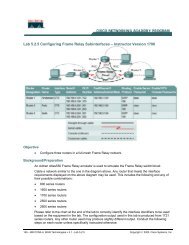
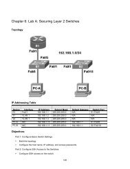
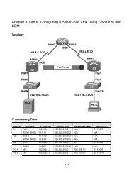
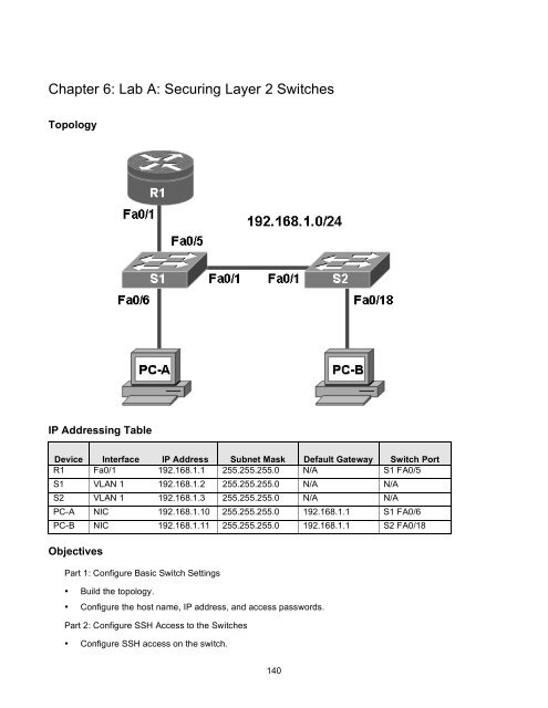
Topology<br />
IP Addressing Table<br />
Device Interface IP Address Subnet Mask Default Gateway Switch Port<br />
R1 Fa0/1 192.168.1.1 255.255.255.0 N/A S1 FA0/5<br />
S1 VLAN 1 192.168.1.2 255.255.255.0 N/A N/A<br />
S2 VLAN 1 192.168.1.3 255.255.255.0 N/A N/A<br />
PC-A NIC 192.168.1.10 255.255.255.0 192.168.1.1 S1 FA0/6<br />
PC-B NIC 192.168.1.11 255.255.255.0 192.168.1.1 S2 FA0/18<br />
Objectives<br />
Part 1: Configure Basic Switch Settings<br />
• Build the topology.<br />
• Configure the host name, IP address, and access passwords.<br />
Part 2: Configure SSH Access to the <strong>Switches</strong><br />
• Configure SSH access on the switch.<br />
140
• Configure an SSH client to access the switch.<br />
• Verify the configuration.<br />
Part 3: Secure Trunks and Access Ports<br />
• Configure trunk port mode.<br />
• Change the native VLAN for trunk ports.<br />
• Verify trunk configuration.<br />
• Enable storm control for broadcasts.<br />
• Configure access ports.<br />
• Enable PortFast and BPDU guard.<br />
• Verify BPDU guard.<br />
• Enable root guard.<br />
• Configure port security.<br />
• Verify port security.<br />
• Disable unused ports.<br />
Part 4: Configure SPAN and Monitor Traffic<br />
• Configure Switched Port Analyzer (SPAN).<br />
• Monitor port activity using Wireshark.<br />
• Analyze a sourced attack.<br />
Background<br />
The <strong>Layer</strong> 2 (Data Link) infrastructure consists mainly of interconnected Ethernet switches. Most end-user<br />
devices, such as computers, printers, IP phones and other hosts, connect to the network via <strong>Layer</strong> 2 access<br />
switches. As a result, they can present a network security risk. Similar to routers, switches are subject to<br />
attack from malicious internal users. The switch Cisco IOS software provides many security features that are<br />
specific to switch functions and protocols.<br />
In this lab, you configure SSH access and <strong>Layer</strong> 2 security for switches S1 and S2. You also configure<br />
various switch protection measures, including access port security, switch storm control, and Spanning Tree<br />
Protocol (STP) features such as BPDU guard and root guard. Lastly, you use Cisco SPAN to monitor traffic to<br />
specific ports on the switch.<br />
Note: The router commands and output in this lab are from a Cisco 1841 with Cisco IOS Release 12.4(20)T<br />
(Advanced IP image). The switch commands and output are from a Cisco WS-C2960-24TT-L with Cisco IOS<br />
Release 12.2(46)SE (C2960-LANBASEK9-M image). Other routers, switches, and IOS versions may be used.<br />
See the Router Interface Summary table at the end of the lab to determine which interface identifiers to use<br />
based on the equipment in the lab. Depending on the router or switch model and IOS version, the commands<br />
available and output produced might vary from what is shown in this lab.<br />
Note: Make sure that the router and the switches have been erased and have no startup configurations.<br />
Required Resources<br />
• One router (Cisco 1841 with Cisco IOS Release 12.4(20)T1 or comparable)<br />
141
• Two switches (Cisco 2960 or comparable with cryptography IOS image for SSH support – Release<br />
12.2(46)SE or comparable)<br />
• PC-A (Windows XP or Vista with a PuTTY SSH client and Wireshark)<br />
• PC-B (Windows XP or Vista with a PuTTY SSH client and SuperScan)<br />
• Ethernet cables as shown in the topology<br />
• Rollover cables to configure the switches via the console<br />
Part 1. Basic Device Configuration<br />
In Part 1 of this lab, you set up the network topology and configure basic settings such as the host names, IP<br />
addresses, and device access passwords.<br />
Note: Perform all tasks on router R1 and switches S1 and S2. The procedure for S1 is shown here as an<br />
example.<br />
Step 1: Cable the network as shown in the topology.<br />
Attach the devices shown in the topology diagram and cable as necessary.<br />
Step 2: Configure basic settings for the router and each switch.<br />
a. Configure host names as shown in the topology.<br />
b. Configure interface IP addresses as shown in the IP Addressing Table. The configuration of the VLAN<br />
1 management interface on switch S1 is shown here.<br />
S1(config)#interface vlan 1<br />
S1(config-if)#ip address 192.168.1.2 255.255.255.0<br />
S1(config-if)#no shutdown<br />
c. Configure the enable secret and console passwords.<br />
S1(config)#enable secret cisco12345<br />
S1(config)#line console 0<br />
S1(config-line)#password ciscoconpass<br />
S1(config-line)#exec-timeout 5 0<br />
S1(config-line)#login<br />
S1(config-line)#logging synchronous<br />
Note: Do not configure the switch vty access at this time. The vty lines are configured on the switches<br />
in Part 2 for SSH access.<br />
d. Configure the vty lines and password on R1.<br />
R1(config)#line vty 0 4<br />
R1(config-line)#password ciscovtypass<br />
R1(config-line)#exec-timeout 5 0<br />
R1(config-line)#login<br />
e. To prevent the router or switch from attempting to translate incorrectly entered commands, disable<br />
DNS lookup. Router R1 is shown here as an example.<br />
142
R1(config)#no ip domain-lookup<br />
f. HTTP access to the switch is enabled by default. To prevent HTTP access, disable the HTTP server<br />
and HTTP secure server.<br />
S1(config)#no ip http server<br />
S1(config)#no ip http secure-server<br />
Note: The switch must have a cryptography IOS image to support the ip http secure-server<br />
command. HTTP access to the router is disabled by default.<br />
Step 3: Configure PC host IP settings.<br />
Configure a static IP address, subnet mask, and default gateway for PC-A and PC-B as shown in the IP<br />
Addressing Table.<br />
Step 4: Verify basic network connectivity.<br />
a. Ping from PC-A and PC-B to the R1 Fa0/1 interface at IP address 192.168.1.1. Were the results<br />
successful? _____<br />
If the pings are not successful, troubleshoot the basic device configurations before continuing.<br />
b. Ping from PC-A to PC-B. Were the results successful? _____<br />
If the pings are not successful, troubleshoot the basic device configurations before continuing.<br />
Step 5: Save the basic configurations for the router and both switches.<br />
Save the running configuration to the startup configuration from the privileged EXEC prompt.<br />
S1#copy running-config startup-config<br />
Part 2. SSH Configuration<br />
In Part 2 of this lab, you configure switches S1 and S2 to support SSH connections and install SSH client<br />
software on the PCs.<br />
Note: A switch IOS image that supports encryption is required to configure SSH. Otherwise, you cannot<br />
specify SSH as an input protocol for the vty lines and the crypto commands are not available.<br />
Task 1. Configure the SSH Server on Switch S1 and S2 Using the CLI<br />
In this task, use the CLI to configure the switch to be managed securely using SSH instead of Telnet. Secure<br />
Shell (SSH) is a network protocol that establishes a secure terminal emulation connection to a switch or other<br />
networking device. SSH encrypts all information that passes over the network link and provides authentication<br />
of the remote computer. SSH is rapidly replacing Telnet as the remote login tool of choice for network<br />
professionals.<br />
Note: For a switch to support SSH, it must be configured with local authentication, AAA services or<br />
username. In this task, you configure an SSH username and local authentication on S1 and S2. S1 is shown<br />
here as an example.<br />
143
Step 1: Configure a domain name.<br />
Enter global configuration mode and set the domain name.<br />
S1#conf t<br />
S1(config)#ip domain-name ccnasecurity.com<br />
Step 2: Configure a privileged user for login from the SSH client.<br />
Use the username command to create the user ID with the highest possible privilege level and a secret<br />
password.<br />
S1(config)#username admin privilege 15 secret cisco12345<br />
Exit to the initial switch login screen, and log in with this username. What was the switch prompt after you<br />
entered the password? __________________________________________________________<br />
Step 3: Configure the incoming vty lines.<br />
a. Configure vty access on lines 0 through 4. Specify a privilege level of 15 so that a user with the highest<br />
privilege level (15) will default to privileged EXEC mode when accessing the vty lines. Other users will<br />
default to user EXEC mode. Specify the use of local user accounts for mandatory login and<br />
validation, and accept only SSH connections.<br />
S1(config)#line vty 0 4<br />
S1(config-line)#privilege level 15<br />
S1(config-line)#exec-timeout 5 0<br />
S1(config-line)#login local<br />
S1(config-line)#transport input ssh<br />
S1(config-line)#exit<br />
b. Disable login for switch vty lines 5 through 15.<br />
S1(config)#line vty 5 15<br />
S1(config-line)#no login<br />
Step 4: Generate the RSA encryption key pair for the router.<br />
The switch uses the RSA key pair for authentication and encryption of transmitted SSH data.<br />
Configure the RSA keys with 1024 for the number of modulus bits. The default is 512, and the range is<br />
from 360 to 2048.<br />
S1(config)#crypto key generate rsa general-keys modulus 1024<br />
The name for the keys will be: S1.ccnasecurity.com<br />
% The key modulus size is 1024 bits<br />
% Generating 1024 bit RSA keys, keys will be non-exportable...[OK]<br />
S1(config)#<br />
00:15:36: %SSH-5-ENABLED: SSH 1.99 has been enabled<br />
Note: The details of encryption methods are covered in <strong>Chapter</strong> 7.<br />
Step 5: Verify the SSH configuration.<br />
Use the show ip ssh command to see the current settings.<br />
S1#show ip ssh<br />
144
Fill in the following information based on the output of the show ip ssh command.<br />
SSH version enabled: __________________<br />
Authentication timeout: __________________<br />
Authentication retries: __________________<br />
Step 6: Configure SSH timeouts and authentication parameters.<br />
The default SSH timeouts and authentication parameters can be altered to be more restrictive using the<br />
following commands.<br />
S1(config)#ip ssh time-out 90<br />
S1(config)#ip ssh authentication-retries 2<br />
Step 7: Save the running-config to the startup-config.<br />
S1#copy running-config startup-config<br />
Task 2. Configure the SSH Client<br />
TeraTerm and PuTTY are two terminal emulation programs that can support SSHv2 client connections. This<br />
lab uses PuTTY.<br />
Step 1: (Optional) Download and install an SSH client on PC-A and PC-B.<br />
If the SSH client is not already installed, download either TeraTerm or PuTTY.<br />
Note: The procedure described here is for PuTTY and pertains to PC-A.<br />
Step 2: Verify SSH connectivity to S1 from PC-A.<br />
a. Launch PuTTY by double-clicking the putty.exe icon.<br />
b. Input the S1 IP address 192.168.1.2 in the Host Name or IP address field.<br />
c. Verify that the SSH radio button is selected. PuTTY defaults to SSH version 2.<br />
145
d. Click Open.<br />
e. In the PuTTY Security Alert window, click Yes.<br />
f. Enter the admin username and password cisco12345 in the PuTTY window.<br />
g. At the S1 privileged EXEC prompt, enter the show users command.<br />
S1#show users<br />
What users are connected to switch S1 at this time?<br />
______________________________________________________________________________<br />
h. Close the PuTTy SSH session window with the exit or quit command.<br />
i. Try to open a Telnet session to switch S1 from PC-A. Were you able to open the Telnet session? Why<br />
or why not? _______________________________________________________________<br />
146
Step 3: Save the configuration.<br />
Save the running configuration to the startup configuration from the privileged EXEC prompt.<br />
R1#copy running-config startup-config<br />
Part 3. Secure Trunks and Access Ports<br />
In Part 3 of this lab, you configure trunk ports, change the native VLAN for trunk ports, verify trunk<br />
configuration, and enable storm control for broadcasts on the trunk ports.<br />
<strong>Securing</strong> trunk ports can help stop VLAN hopping attacks. The best way to prevent a basic VLAN hopping<br />
attack is to turn off trunking on all ports except the ones that specifically require trunking. On the required<br />
trunking ports, disable DTP (auto trunking) negotiations and manually enable trunking. If no trunking is<br />
required on an interface, configure the port as an access port. This disables trunking on the interface.<br />
Note: Tasks should be performed on switches S1 or S2 as indicated.<br />
Task 1. Secure Trunk Ports<br />
Step 1: Configure switch S1 as the root switch.<br />
For the purposes of this lab, assume that switch S2 is currently the root bridge and that switch S1 is preferred<br />
as the root switch. To force S1 to become the new root bridge, you configure a new priority for it.<br />
a. From the console on S1, enter privileged EXEC mode and then global configuration mode.<br />
The default priority for switches S1 and S2 is 32769 (32768 + 1 with System ID Extension). Set S1 priority<br />
to 0 so that it becomes the root switch.<br />
S1(config)#spanning-tree vlan 1 priority 0<br />
S1(config)#exit<br />
b. Issue the show spanning-tree command to verify that S1 is the root bridge and to see the ports in<br />
use and their status.<br />
S1#show spanning-tree<br />
VLAN0001<br />
Spanning tree enabled protocol ieee<br />
Root ID Priority 1<br />
Address 001d.4635.0c80<br />
This bridge is the root<br />
Hello Time 2 sec Max Age 20 sec Forward Delay 15 sec<br />
Bridge ID Priority 1 (priority 0 sys-id-ext 1)<br />
Address 001d.4635.0c80<br />
Hello Time 2 sec Max Age 20 sec Forward Delay 15 sec<br />
Aging Time 300<br />
Interface Role Sts Cost Prio.Nbr Type<br />
---------------- ---- --- --------- -------- --------------------------<br />
------<br />
Fa0/1 Desg FWD 19 128.1 P2p<br />
Fa0/5 Desg FWD 19 128.5 P2p<br />
Fa0/6 Desg FWD 19 128.6 P2p<br />
147
c. What is the S1 priority? ______________________________________________________<br />
d. What ports are in use and what is their status? ____________________________________<br />
Step 2: Configure trunk ports on S1 and S2.<br />
a. Configure port Fa0/1 on S1 as a trunk port.<br />
S1(config)#interface FastEthernet 0/1<br />
S1(config-if)#switchport mode trunk<br />
b. Configure port Fa0/1 on S2 as a trunk port.<br />
S2(config)#interface FastEthernet 0/1<br />
S2(config-if)#switchport mode trunk<br />
c. Verify that S1 port Fa0/1 is in trunking mode with the show interfaces trunk command.<br />
S1#show interfaces trunk<br />
Port Mode Encapsulation Status Native vlan<br />
Fa0/1 on 802.1q trunking 1<br />
Port Vlans allowed on trunk<br />
Fa0/1 1-4094<br />
Port Vlans allowed and active in management domain<br />
Fa0/1 1<br />
Port Vlans in spanning tree forwarding state and not pruned<br />
Fa0/1 1<br />
Step 3: Change the native VLAN for the trunk ports on S1 and S2.<br />
Changing the native VLAN for trunk ports to an unused VLAN helps prevent VLAN hopping attacks.<br />
a. From the output of the show interfaces trunk in the previous step, what is the current native<br />
VLAN for the S1 Fa0/1 trunk interface? ______________________________________________<br />
b. Set the native VLAN on the S1 Fa0/1 trunk interface to an unused VLAN 99.<br />
S1(config)#interface Fa0/1<br />
S1(config-if)#switchport trunk native vlan 99<br />
S1(config-if)#end<br />
The following message should be displayed after a brief period of time.<br />
02:16:28: %CDP-4-NATIVE_VLAN_MISMATCH: Native VLAN mismatch discovered<br />
on FastEthernet0/1 (99), with S2 FastEthernet0/1 (1).<br />
What does the message mean? __________________________________________________<br />
c. Set the native VLAN on the S2 Fa0/1 trunk interface to VLAN 99.<br />
S2(config)#interface Fa0/1<br />
S2(config-if)#switchport trunk native vlan 99<br />
S2(config-if)#end<br />
148
Step 4: Prevent the use of DTP on S1 and S2.<br />
Setting the trunk port to not negotiate also helps to mitigate VLAN hopping by turning off the generation of<br />
DTP frames.<br />
S1(config)#interface Fa0/1<br />
S1(config-if)#switchport nonegotiate<br />
S2(config)#interface Fa0/1<br />
S2(config-if)#switchport nonegotiate<br />
Step 5: Verify the trunking configuration on port Fa0/1.<br />
S1#show interface fa0/1 trunk<br />
Port Mode Encapsulation Status Native vlan<br />
Fa0/1 on 802.1q trunking 99<br />
Port Vlans allowed on trunk<br />
Fa0/1 1-4094<br />
Port Vlans allowed and active in management domain<br />
Fa0/1 1<br />
Port Vlans in spanning tree forwarding state and not pruned<br />
Fa0/1 1<br />
S1#show interface fa0/1 switchport<br />
Name: Fa0/1<br />
Switchport: Enabled<br />
Administrative Mode: trunk<br />
Operational Mode: trunk<br />
Administrative Trunking Encapsulation: dot1q<br />
Operational Trunking Encapsulation: dot1q<br />
Negotiation of Trunking: Off<br />
Access Mode VLAN: 1 (default)<br />
Trunking Native Mode VLAN: 99 (Inactive)<br />
Administrative Native VLAN tagging: enabled<br />
Voice VLAN: none<br />
Administrative private-vlan host-association: none<br />
Administrative private-vlan mapping: none<br />
Administrative private-vlan trunk native VLAN: none<br />
Administrative private-vlan trunk Native VLAN tagging: enabled<br />
Administrative private-vlan trunk encapsulation: dot1q<br />
Administrative private-vlan trunk normal VLANs: none<br />
Administrative private-vlan trunk private VLANs: none<br />
Operational private-vlan: none<br />
Trunking VLANs Enabled: ALL<br />
Pruning VLANs Enabled: 2-1001<br />
Capture Mode Disabled<br />
Capture VLANs Allowed: ALL<br />
Protected: false<br />
Unknown unicast blocked: disabled<br />
Unknown multicast blocked: disabled<br />
Appliance trust: none<br />
149
Step 6: Enable storm control for broadcasts.<br />
Enable storm control for broadcasts on the trunk port with a 50 percent rising suppression level using the<br />
storm-control broadcast command.<br />
S1(config)#interface FastEthernet 0/1<br />
S1(config-if)#storm-control broadcast level 50<br />
S2(config)#interface FastEthernet 0/1<br />
S2(config-if)#storm-control broadcast level 50<br />
Step 7: Verify your configuration with the show run command.<br />
Use the show run command to display the running configuration, beginning with the first line that has<br />
the text string “0/1” in it.<br />
S1#show run | beg 0/1<br />
interface FastEthernet0/1<br />
switchport trunk native vlan 99<br />
switchport mode trunk<br />
switchport nonegotiate<br />
storm-control broadcast level 50.00<br />
<br />
Task 2. Secure Access Ports<br />
By manipulating the STP root bridge parameters, network attackers hope to spoof their system, or a rogue<br />
switch that they add to the network, as the root bridge in the topology. If a port that is configured with PortFast<br />
receives a BPDU, STP can put the port into the blocking state by using a feature called BPDU guard.<br />
Step 1: Disable trunking on S1 access ports.<br />
On S1, configure Fa0/5, the port to which R1 is connected, as access mode only.<br />
S1(config)#interface FastEthernet 0/5<br />
S1(config-if)#switchport mode access<br />
On S1, configure Fa0/6, the port to which PC-A is connected, as access mode only.<br />
S1(config)#interface FastEthernet 0/6<br />
S1(config-if)#switchport mode access<br />
On S2, configure Fa0/18, the port to which PC-B is connected, as access mode only.<br />
S2(config)#interface FastEthernet 0/18<br />
S2(config-if)#switchport mode access<br />
Task 3. Protect Against STP Attacks<br />
The topology has only two switches and no redundant paths, but STP is still active. In this step, you enable<br />
some switch security features that can help reduce the possibility of an attacker manipulating switches via<br />
STP-related methods.<br />
Step 1: Enable PortFast on S1 and S2 access ports.<br />
PortFast is configured on access ports that connect to a single workstation or server to enable them to<br />
become active more quickly.<br />
150
a. Enable PortFast on the S1 Fa0/5 access port.<br />
S1(config)#interface FastEthernet 0/5<br />
S1(config-if)#spanning-tree portfast<br />
The following Cisco IOS warning message is displayed:<br />
%Warning: portfast should only be enabled on ports connected to a<br />
single host. Connecting hubs, concentrators, switches, bridges, etc...<br />
to this interface when portfast is enabled, can cause temporary<br />
bridging loops. Use with CAUTION<br />
%Portfast has been configured on FastEthernet0/5 but will only<br />
have effect when the interface is in a non-trunking mode.<br />
b. Enable PortFast on the S1 Fa0/6 access port.<br />
S1(config)#interface FastEthernet 0/6<br />
S1(config-if)#spanning-tree portfast<br />
c. Enable PortFast on the S2 Fa0/18 access ports<br />
S2(config)#interface FastEthernet 0/18<br />
S2(config-if)#spanning-tree portfast<br />
Step 2: Enable BPDU guard on the S1 and S2 access ports.<br />
BPDU guard is a feature that can help prevent rogue switches and spoofing on access ports.<br />
a. Enable BPDU guard on the switch ports previously configured as access only.<br />
S1(config)#interface FastEthernet 0/5<br />
S1(config-if)#spanning-tree bpduguard enable<br />
S1(config)#interface FastEthernet 0/6<br />
S1(config-if)#spanning-tree bpduguard enable<br />
S2(config)#interface FastEthernet 0/18<br />
S2(config-if)#spanning-tree bpduguard enable<br />
b. PortFast and BPDU guard can also be enabled globally with the spanning-tree portfast<br />
default and spanning-tree portfast bpduguard commands in global configuration mode.<br />
Note: BPDU guard can be enabled on all access ports that have PortFast enabled. These ports<br />
should never receive a BPDU. BPDU guard is best deployed on user-facing ports to prevent rogue<br />
switch network extensions by an attacker. If a port enabled with BPDU guard receives a BPDU, it is<br />
disabled and must be manually re-enabled. An err-disable timeout can be configured on the port so<br />
that it can recover automatically after a specified time period.<br />
c. Verify that BPDU guard is configured by using the show spanning-tree interface fa0/5<br />
detail command on switch S1.<br />
S1#show spanning-tree interface fa0/5 detail<br />
Port 5 (FastEthernet0/5) of VLAN0001 is designated forwarding<br />
Port path cost 19, Port priority 128, Port Identifier 128.5.<br />
Designated root has priority 1, address 001d.4635.0c80<br />
Designated bridge has priority 1, address 001d.4635.0c80<br />
Designated port id is 128.5, designated path cost 0<br />
Timers: message age 0, forward delay 0, hold 0<br />
Number of transitions to forwarding state: 1<br />
151
The port is in the portfast mode<br />
Link type is point-to-point by default<br />
Bpdu guard is enabled<br />
BPDU: sent 3349, received 0<br />
Step 3: (Optional) Enable root guard.<br />
Root guard is another option in helping to prevent rogue switches and spoofing. Root guard can be enabled<br />
on all ports on a switch that are not root ports. It is normally enabled only on ports connecting to edge<br />
switches where a superior BPDU should never be received. Each switch should have only one root port,<br />
which is the best path to the root switch.<br />
The following command configures root guard on S2 interface Gi0/1. Normally, this is done if another<br />
switch is attached to this port. Root guard is best deployed on ports that connect to switches that<br />
should not be the root bridge.<br />
S2(config)#interface gigabitEthernet 0/1<br />
S2(config-if)#spanning-tree guard root<br />
a. Issue the show run command to verify that root guard is configured.<br />
S2#sh run | beg Gig<br />
interface GigabitEthernet0/1<br />
spanning-tree guard root<br />
Note: The S2 Gi0/1 port is not currently up, so it is not participating in STP. Otherwise, you could use<br />
the show spanning-tree interface Gi0/1 detail command.<br />
b. If a port that is enabled with BPDU guard receives a superior BPDU, it goes into a root-inconsistent<br />
state. Use the show spanning-tree inconsistentports command to determine if there are any<br />
ports currently receiving superior BPDUs that should not be.<br />
S2#show spanning-tree inconsistentports<br />
Name Interface Inconsistency<br />
-------------------- ---------------------- ------------------<br />
Number of inconsistent ports (segments) in the system : 0<br />
Note: Root guard allows a connected switch to participate in STP as long as the device does not try to<br />
become the root. If root guard blocks the port, subsequent recovery is automatic. If the superior BPDUs<br />
stop, the port returns to the forwarding state.<br />
Task 4. Configure Port Security and Disable Unused Ports<br />
<strong>Switches</strong> can also be subject to CAM table overflow, MAC spoofing attacks, and unauthorized connections to<br />
switch ports. In this task, you configure port security to limit the number of MAC addresses that can be<br />
learned on a switch port and disable the port if that number is exceeded.<br />
Step 1: Record the R1 Fa0/0 MAC address.<br />
a. From the router R1 CLI, use the show interface command and record the MAC address of the<br />
interface.<br />
R1#show interface fa0/1<br />
FastEthernet0/1 is up, line protocol is up<br />
Hardware is Gt96k FE, address is 001b.5325.256f (bia 001b.5325.256f)<br />
Internet address is 192.168.1.1/24<br />
MTU 1500 bytes, BW 100000 Kbit/sec, DLY 100 usec,<br />
152
eliability 255/255, txload 1/255, rxload 1/255<br />
Encapsulation ARPA, loopback not set<br />
Keepalive set (10 sec)<br />
Full-duplex, 100Mb/s, 100BaseTX/FX<br />
b. What is the MAC address of the R1 Fa0/1 interface? _____________________________________<br />
Step 2: Configure basic port security.<br />
This procedure should be performed on all access ports that are in use. Switch S1 port Fa0/5 is shown here<br />
as an example.<br />
Note: A switch port must be configured as an access port to enable port security.<br />
a. From the switch S1 CLI, enter interface configuration mode for the port that connects to the router<br />
(Fast Ethernet 0/5).<br />
S1(config)#interface FastEthernet 0/5<br />
b. Shut down the switch port.<br />
S1(config-if)#shutdown<br />
c. Enable port security on the port.<br />
S1(config-if)#switchport port-security<br />
Note: Entering just the switchport port-security command sets the maximum MAC<br />
addresses to 1 and the violation action to shutdown. The switchport port-security maximum<br />
and switchport port-security violation commands can be used to change the default<br />
behavior.<br />
d. Configure a static entry for the MAC address of R1 Fa0/1/ interface recorded in Step 1.<br />
S1(config-if)#switchport port-security mac-address xxxx.xxxx.xxxx<br />
(xxxx.xxxx.xxxx is the actual MAC address of the router Fast Ethernet 0/1 interface.)<br />
Note: Optionally, you can use the switchport port-security mac-address sticky<br />
command to add all the secure MAC addresses that are dynamically learned on a port (up to the<br />
maximum set) to the switch running configuration.<br />
e. Bring up the switch port.<br />
S1(config-if)#no shutdown<br />
Step 3: Verify port security on S1 Fa0/5.<br />
On S1, issue the show port-security command to verify that port security has been configured on<br />
S1 Fa0/5.<br />
S1#show port-security interface f0/5<br />
Port Security<br />
: Enabled<br />
Port Status<br />
: Secure-up<br />
Violation Mode<br />
: Shutdown<br />
Aging Time<br />
: 0 mins<br />
Aging Type<br />
: Absolute<br />
SecureStatic Address Aging : Disabled<br />
Maximum MAC Addresses : 1<br />
Total MAC Addresses : 1<br />
Configured MAC Addresses : 1<br />
153
Sticky MAC Addresses : 0<br />
Last Source Address:Vlan : 001b.5325.256f:1<br />
Security Violation Count : 0<br />
What is the status of the Fa0/5 port? ___________________________________________________<br />
What is the Last Source Address and VLAN? _______________________________________________<br />
From the router R1 CLI, ping PC-A to verify connectivity. This also ensures that the R1 Fa0/1 MAC<br />
address is learned by the switch.<br />
R1#ping 192.168.1.10<br />
You will now violate security by changing the MAC address on the router interface. Enter interface<br />
configuration mode for the Fast Ethernet 0/1 interface and shut it down.<br />
R1(config)#interface FastEthernet 0/1<br />
R1(config-if)#shutdown<br />
Configure a MAC address for the interface on the interface, using aaaa.bbbb.cccc as the address.<br />
R1(config-if)#mac-address aaaa.bbbb.cccc<br />
Enable the Fast Ethernet 0/1 interface.<br />
R1(config-if)#no shutdown<br />
R1(config-if)#end<br />
From the router R1 CLI, ping PC-A. Was the ping successful? Why or why not?<br />
_______________________________________________________________________________<br />
On switch S1 console, observe the messages when port Fa0/5 detects the violating MAC address.<br />
*Jan 14 01:34:39.750: %PM-4-ERR_DISABLE: psecure-violation error<br />
detected on Fa0/5, putting Fa0/5 in err-disable state<br />
*Jan 14 01:34:39.750: %PORT_SECURITY-2-PSECURE_VIOLATION: Security<br />
violation occurred, caused by MAC address aaaa.bbbb.cccc on port<br />
FastEthernet0/5.<br />
*Jan 14 01:34:40.756: %LINEPROTO-5-UPDOWN: Line protocol on Interface<br />
FastEthernet0/5, changed state to down<br />
*Mar 1 01:34:41.755: %LINK-3-UPDOWN: Interface FastEthernet0/5,<br />
changed state to down<br />
On the switch, use the various show port-security commands to verify that port security has been<br />
violated.<br />
S1#show port-security<br />
Secure Port MaxSecureAddr CurrentAddr SecurityViolation Security Action<br />
(Count) (Count) (Count)<br />
Fa0/5 1 1 1 Shutdown<br />
S1#show port-security interface fastethernet0/5<br />
Port Security<br />
: Enabled<br />
Port Status<br />
: Secure-shutdown<br />
Violation Mode<br />
: Shutdown<br />
Aging Time<br />
: 0 mins<br />
Aging Type<br />
: Absolute<br />
SecureStatic Address Aging : Disabled<br />
Maximum MAC Addresses : 1<br />
Total MAC Addresses : 1<br />
Configured MAC Addresses : 1<br />
Sticky MAC Addresses : 0<br />
154
Last Source Address:Vlan : aaaa.bbbb.cccc:1<br />
Security Violation Count : 1<br />
S1#show port-security address<br />
Secure Mac Address Table<br />
Vlan Mac Address Type Ports Remaining Age<br />
(mins)<br />
---- ----------- ---- ----- -------------<br />
1 001b.5325.256f SecureConfigured Fa0/5 -<br />
On the router, shut down the Fast Ethernet 0/1 interface, remove the hard-coded MAC address from the<br />
router, and re-enable the Fast Ethernet 0/1 interface.<br />
R1(config)#interface FastEthernet 0/1<br />
R1(config-if)#shutdown<br />
R1(config-if)#no mac-address aaaa.bbbb.cccc<br />
R1(config-if)#no shutdown<br />
Note: This will restore the original FastEthernet interface MAC address.<br />
From R1, try to ping the PC-A again at 192.168.1.10. Was the ping successful? Why or why not?<br />
________________________________________________________________________________<br />
Step 4: Clear the S1 Fa0/5 error disabled status.<br />
a. From the S1 console, clear the error and re-enable the port using the following commands. This will<br />
change the port status from Secure-shutdown to Secure-up.<br />
S1(config)#interface FastEthernet 0/5<br />
S1(config-if)#shutdown<br />
S1(config-if)#no shutdown<br />
Note: This assumes the device/interface with the violating MAC address has been removed and replaced<br />
with the one originally configured.<br />
b. From R1, ping PC-A again. You should be successful this time.<br />
R1#ping 192.168.1.10<br />
Step 5: Remove basic port security on S1 Fa0/5.<br />
a. From the S1 console, remove port security on Fa0/5. This procedure can also be used to re-enable the<br />
port but port security commands will need to be reconfigured.<br />
S1(config)#interface FastEthernet 0/5<br />
S1(config-if)#shutdown<br />
S1(config-if)#no switchport port-security<br />
S1(config-if)#no switchport port-security mac-address 001b.5325.256f<br />
S1(config-if)#no shutdown<br />
b. You can also use the following commands to reset the interface to its default settings.<br />
S1(config)#interface FastEthernet 0/5<br />
S1(config-if)#shutdown<br />
S1(config-if)#exit<br />
S1(config)#default interface fastethernet 0/5<br />
S1(config)#interface FastEthernet 0/5<br />
S1(config-if)#no shutdown<br />
155
Note: This default interface command also requires you to reconfigure the<br />
port as an access port in order to re-enable the security commands.<br />
Step 6: (Optional) Configure port security for VoIP.<br />
The following example shows a typical port security configuration for a voice port. Two MAC addresses<br />
are allowed, and they are to be learned dynamically. One MAC address is for the IP phone, and the other<br />
IP address is for the PC connected to the IP phone. Violations of this policy result in the port being shut<br />
down. The aging timeout for the learned MAC addresses is set to two hours.<br />
This example is shown for switch S2 port Fa0/18.<br />
S2(config)#interface Fa0/18<br />
S2(config-if)#switchport mode access<br />
S2(config-if)#switchport port-security<br />
S2(config-if)#switchport port-security maximum 2<br />
S2(config-if)#switchport port-security violation shutdown<br />
S2(config-if)#switchport port-security mac-address sticky<br />
S2(config-if)#switchport port-security aging time 120<br />
Step 7: Disable unused ports on S1 and S2.<br />
As a further security measure, disable any ports not being used on the switch.<br />
a. Ports Fa0/1, Fa0/5, and Fa0/6 are used on switch S1. The remaining Fast Ethernet ports and the two<br />
Gigabit Ethernet ports will be shutdown.<br />
S1(config)#interface range Fa0/2 – 4<br />
S1(config-if-range)#shutdown<br />
S1(config-if-range)#interface range Fa0/7 – 24<br />
S1(config-if-range)#shutdown<br />
S1(config-if-range)#interface range gigabitethernet0/1 – 2<br />
S1(config-if-range)#shutdown<br />
b. Ports Fa0/18 and Gi0/1 are used on switch S2. The remaining Fast Ethernet ports and the Gigabit<br />
Ethernet ports will be shutdown.<br />
S2(config)#interface range Fa0/2 - 17<br />
S2(config-if-range)#shutdown<br />
S2(config-if-range)#interface range Fa0/19 - 24<br />
S2(config-if-range)#shutdown<br />
S2(config-if-range)#exit<br />
S2(config)#interface gigabitethernet0/2<br />
S2(config-if)#shutdown<br />
Step 8: (Optional) Move active ports to a VLAN other than the default VLAN 1<br />
As a further security measure, you can move all active end user and router ports to a VLAN other than the<br />
default VLAN 1 on both switches.<br />
a. Configure a new VLAN for users on each switch using the following commands:<br />
S1(config)#vlan 20<br />
S1(config-vlan)#name Users<br />
S2(config)#vlan 20<br />
S2(config-vlan)#name Users<br />
b. Add the current active access (non-trunk) ports to the new VLAN.<br />
156
S1(config)#interface range fa0/5 - 6<br />
S1(config-if)#switchport access vlan 20<br />
S2(config)#interface fa0/18<br />
S2(config-if)#switchport access vlan 20<br />
Note: This will prevent communication between end user hosts and the management VLAN IP address of the<br />
switch, which is currently VLAN 1. The switch can still be accessed and configured using the console<br />
connection.<br />
If you need to provide Telnet or SSH access to the switch, a specific port can be designated as the<br />
management port and added to VLAN 1 with a specific management workstation attached. A more elaborate<br />
solution is to create a new VLAN for switch management (or use the existing native trunk VLAN 99) and<br />
configure a separate subnet for the management and user VLANs. Enable trunking with subinterfaces on R1<br />
to route between the management and user VLAN subnets.<br />
Part 4. Configure SPAN and Monitor Traffic<br />
Note: There are two tasks in this part of the lab, Task 1: Option 1 is to be performed using hands-on<br />
equipment. Task 2: Option 2 is modified to be compatible with the NETLAB+ system but can also be<br />
performed using hands-on equipment.<br />
Cisco IOS provides a feature that can be used to monitor network attacks called Switched Port Analyzer<br />
(SPAN). Cisco IOS supports local SPAN and remote SPAN (RSPAN). With local SPAN, the source VLANs,<br />
source switch ports, and the destination switch ports are on the same physical switch.<br />
In this part of the lab, you configure a local SPAN to copy traffic from one port where a host is connected to<br />
another port where a monitoring station is connected. The monitoring station will run the Wireshark packet<br />
sniffer application to analyze traffic.<br />
Note: SPAN allows you to select and copy traffic from one or more source switch ports or source VLANs onto<br />
one or more destination ports.<br />
Task 1. Option 1: Configure a SPAN Session Using Hands-on Equipment.<br />
Note: Option 1 assumes you have physical access to the devices shown in the topology for this<br />
lab. NETLAB+ users accessing lab equipment remotely should proceed to Task 2: Option 2.<br />
Step 1: Configure a SPAN session on S1 with a source and destination<br />
a. Set the SPAN source interface using the monitor session command in global configuration mode.<br />
The following configures a SPAN source port on FastEthernet 0/5 for ingress and egress traffic.<br />
Traffic copied on the source port can be ingress only, egress only or both. Switch S1 port Fa0/5 is<br />
connected to router R1, so traffic to (ingress) and from (egress) switch port Fa0/5 to R1 will be<br />
monitored.<br />
S1(config)#monitor session 1 source interface fa0/5 both<br />
Note: You can specify to monitor tx (transmit) or rx (receive) traffic. The keyword both includes tx<br />
and rx. The source can be a single interface, a range of interfaces, a single VLAN, or a range of<br />
VLANs.<br />
b. Set the SPAN destination interface.<br />
S1(config)#monitor session 1 destination interface fa0/6<br />
157
All traffic from S1 Fa0/5, where R1 is connected, will be copied to the SPAN destination port Fa0/6, where<br />
PC-A with Wireshark is connected.<br />
Note: The destination can be an interface or a range of interfaces.<br />
Step 2: Verify the setup of the SPAN session on S1.<br />
Confirm the SPAN session setup.<br />
S1#show monitor session 1<br />
Session 1<br />
Type<br />
: Local Session<br />
Source Ports :<br />
Both<br />
: Fa0/5<br />
Destination Ports : Fa0/6<br />
Encapsulation : Native<br />
Ingress : Disabled<br />
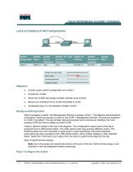
Step 3: (Optional) Download and install Wireshark on PC-A.<br />
a. Wireshark is a network protocol analyzer (also called a packet sniffer) that runs with Windows XP and<br />
Vista. If Wireshark is not currently available on PC-A, you can download the latest version from<br />
http://www.wireshark.org/download.html. This lab uses Wireshark version 1.0.5. The initial Wireshark<br />
installation screen is shown here.<br />
b. Click I Agree to the License agreement and accept the defaults by clicking Next when prompted.<br />
Note: On the Install WinPcap screen, select the install WinPcap options and select Start WinPcap<br />
service option if you want to have other users besides those with administrative privileges run Wireshark.<br />
158
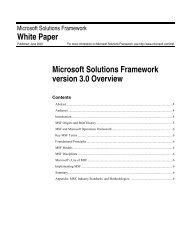
Step 4: Monitor switch S1 port Fa0/5 ping activity using Wireshark on PC-A.<br />
a. If Wireshark is available, start the application.<br />
b. From the main menu, select Capture > Interfaces.<br />
c. Click the Start button for the local area network interface adapter with IP address 192.168.1.10.<br />
d. Generate some traffic from PC-B (192.168.1.11) to R1 interface Fa0/1 (192.168.1.1) using ping. This<br />
traffic will go from S2 port Fa0/18 to S2 port Fa0/1 across the trunk link to S1 port Fa0/1 and then exit<br />
interface Fa0/5 on S1 to reach R1.<br />
PC-B:\>ping 192.168.1.1<br />
e. Observe the results in Wireshark on PC-A. Notice the initial ARP request broadcast from PC-B (Intel<br />
NIC) to determine the MAC address of the R1 Fa0/1 interface with IP address 192.168.1.1 and the ARP<br />
reply from the R1 Cisco Ethernet interface. After the ARP request, the pings (echo request and replies)<br />
can be seen going from PC-B to R1 and from R1 to PC-B through the switch.<br />
Note: Your screen should look similar to the one below. Some additional packets might be captured<br />
in addition to the pings, such as the R1 Fa0/1 LOOP reply.<br />
159
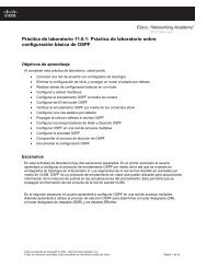
Step 5: Monitor switch S1 port Fa0/5 SuperScan activity using Wireshark on PC-A.<br />
a. If SuperScan is not on PC-B, download the SuperScan 4.0 tool from the Scanning Tools group at<br />
http://www.foundstone.com. Unzip the file into a folder. The SuperScan4.exe file is executable and<br />
installation is not required.<br />
b. Start the SuperScan program on PC-B. Click the Host and Service Discovery tab. Check the<br />
Timestamp Request check box, and uncheck the Echo Request check box. Scroll through the UDP and<br />
TCP port selection lists and notice the range of ports that will be scanned.<br />
c. In the SuperScan program, click the Scan tab and enter the IP address R1 FA0/1 (192.168.1.1) in the<br />
Hostname/IP field.<br />
d. Click the right arrow to populate the Start IP and End IP fields.<br />
160
e. Clear the previous capture in Wireshark and start a new capture by clicking Capture > Start. When<br />
prompted, click the Continue without saving button.<br />
f. In the SuperScan program, click the blue arrow button in the lower left to start the scan.<br />
g. Observe the results in the Wireshark window on PC-A. Notice the number and types of ports tried by<br />
the simulated SuperScan attack from PC-B (192.168.1.11) to R1 Fa0/1 (192.168.1.1). Your screen should<br />
look similar to the following:<br />
161
Task 2. Option 2: Configure a SPAN Session Using NETLAB+ Remote Equipment.<br />
Note: This portion of the lab has been rewritten to enhance compatibility with the NETLAB+<br />
system.<br />
On switch S1, you will configure a local SPAN to reflect the traffic exiting Port Fa0/5, in this case, the traffic<br />
from PC-A to R1’s Fa0/1. This traffic should be received by switch S2, and forwarded to PC-B, where<br />
Wireshark is capturing the packets. Refer to the following diagram which illustrates the SPAN traffic flow.<br />
Note: To perform this Task, Wireshark should be installed on PC-B.<br />
162
Note: Switch S2 is acting as a regular switch, forwarding frames based on destination MAC addresses and<br />
switch ports. The traffic entering S2 through Port Fa0/1 utilizes the R1’s MAC address as destination for the<br />
Ethernet frame, therefore in order to forward those packets to PC-B, the R1’s MAC address must be the same<br />
as PC-B. To accomplish this, R1’s Fa0/1 MAC address is modified using the IOS CLI to simulate PC-B’s MAC<br />
address. This requirement is specific to the NETLAB+ environment.<br />
Step 1: Configure a SPAN session on S1 with Source and Destination:<br />
a. Return the Fa0/1 on S1 and S2 to its default configuration. This link S1 Fa0/1 to S2 Fa0/1 is going to<br />
be used to carry the traffic being monitored.<br />
S1(config)#default interface fastethernet 0/1<br />
S2(config)#default interface fastethernet 0/1<br />
b. Write down the MAC address for PC-B<br />
PC-B’s MAC Address: ___________________________<br />
PC-B’s MAC Address in this example is 000c-299a-e61a<br />
c. Configure the PC-B’s MAC address on R1’s Fa0/1.<br />
R1(config)#interface fa0/1<br />
R1(config-if)#mac-address 000c.299a.e61a<br />
d. Set the SPAN Source Interface using the monitor session command in global configuration mode. The<br />
following configures a SPAN source port on fastethernet0/5 for egress traffic. Traffic copied on the source<br />
port can be ingress only, egress only or both. In this case, the egress traffic is the only one analyzed. On<br />
Switch S1 port Fa0/5 is connected to router R1 so traffic to the switch port Fa0/5 to R1 will be monitored.<br />
S1(config)#monitor session 1 source interface fa0/5 tx<br />
Note: The source can be a single interface, a range of interfaces, a single VLAN, or range of VLANs.<br />
163
e. Set the SPAN destination interface.<br />
S1(config)#monitor session 1 destination interface fa0/1<br />
All egress traffic from S1 Fa0/5, where R1 is connected, will be copied to the SPAN destination port<br />
Fa0/1, where PC-B with WireShark is connected.<br />
Note: The destination can be an interface or a range of interfaces.<br />
Step 2: Verify the setup of the SPAN session on S1.<br />
Confirm the SPAN session setup using the show monitor session 1 command.<br />
S1#show monitor session 1<br />
Session 1<br />
Type<br />
: Local Session<br />
Source Ports :<br />
TX Only<br />
: Fa0/5<br />
Destination Ports : Fa0/1<br />
Encapsulation : Native<br />
Ingress : Disabled<br />
Step 3: (Optional) Download and install Wireshark on PC-B<br />
WireShark is a network protocol analyzer (also called a packet sniffer) that runs with Windows XP and<br />
Vista. If WireShark is not currently available on PC-B, you may download the latest version from<br />
http://www.wireshark.org/download.html and install it as described in Part 4, Task 1, Step 3.<br />
Step 4: Monitor Switch S1 port Fa0/5 ping activity using Wireshark on PC-B<br />
a. If WireShark is available, start the application.<br />
b. From the main menu, select Capture > Interfaces.<br />
c. Click the Start button for the Local area network interface adapter.<br />
d. Generate some traffic from PC-A (192.168.1.10) to R1 interface Fa0/1 (192.168.1.1) using ping. This<br />
traffic will go from S1 port Fa0/6 to S1 port Fa0/5. In addition, the traffic going from PC-A to R1 interface<br />
Fa0/1 is forwarded across the link between S1 and S2, and then S2 will forward this traffic to PC-B,<br />
where Wireshark is capturing the packets. Before pinging, delete the ARP table on PC-A, so an ARP<br />
request would be generated. Note that the SPAN session is configured only on S1, and S2 is operating<br />
as a normal switch.<br />
C:\>arp –d *<br />
C:\>ping 192.168.1.1<br />
e. Observe the results in WireShark on PC-B. Notice the initial ARP request broadcast from PC-A to<br />
determine the MAC address of the R1 Fa0/1 interface with IP address 192.168.1.1 and the ARP reply<br />
from the R1 Cisco Ethernet interface. After the ARP request the pings (echo requests) can be seen going<br />
from PC-A to R1 through the switch.<br />
Note: Your screen should look similar to the one below. There may be some addition packets captured,<br />
in addition to the pings, such as the R1 Fa0/1 LOOP Reply and Spanning Tree Packets.<br />
164
Step 5: Monitor Switch S1 port Fa0/5 SuperScan activity using Wireshark on PC-B<br />
a. If SuperScan is not on PC-A, download the SuperScan 4.0 tool from the Scanning Tools group at<br />
http://www.foundstone.com. Unzip the file into a folder. The SuperScan4.exe file is executable and<br />
installation is not required.<br />
b. Start the SuperScan program on PC-A. Click the Host and Service Discovery tab. Check the<br />
Timestamp Request check box and uncheck the Echo Request check box. Scroll the UDP and TCP<br />
port selection lists and notice the range of ports that will be scanned.<br />
c. In the SuperScan program click the Scan tab and enter the IP address of R1 FA0/1 (192.168.1.1) in<br />
the Hostname/IP field.<br />
d. Click the right facing arrow to populate the Start and End IP fields.<br />
165
e. Clear the previous capture in WireShark and start a new capture by clicking Capture > Start and when<br />
prompted click the Continue without saving button.<br />
f. In the SuperScan program click the button which is in the lower left of the screen, with the blue arrow on<br />
it, to start the scan.<br />
g. Observe the results on the WireShark window on PC-B. Notice the number and types of ports tried by<br />
the simulated SuperScan attack from PC-A (192.168.1.11) to R1 Fa0/1 (192.168.1.1). Your screen should<br />
look similar the following:<br />
166
Step 6: Reflection.<br />
a. Why should port security be enabled on switch access ports?<br />
____________________________________________________________________________________<br />
____________________________________________________________________________<br />
b. Why should port security be enabled on switch trunk ports?<br />
____________________________________________________________________________________<br />
____________________________________________________________________________<br />
c. Why should unused ports on a switch be disabled?<br />
____________________________________________________________________________________<br />
____________________________________________________________________________<br />
Router Interface Summary Table<br />
Router Model Ethernet Interface<br />
#1<br />
1700 Fast Ethernet 0<br />
(FA0)<br />
Router Interface Summary<br />
Ethernet Interface<br />
#2<br />
Fast Ethernet 1<br />
(FA1)<br />
Serial Interface<br />
#1<br />
Serial 0 (S0)<br />
Serial Interface<br />
#2<br />
Serial 1 (S1)<br />
167
1800 Fast Ethernet 0/0<br />
(FA0/0)<br />
2600 Fast Ethernet 0/0<br />
(FA0/0)<br />
2800 Fast Ethernet 0/0<br />
(FA0/0)<br />
Router Interface Summary<br />
Fast Ethernet 0/1<br />
(FA0/1)<br />
Fast Ethernet 0/1<br />
(FA0/1)<br />
Fast Ethernet 0/1<br />
(FA0/1)<br />
Serial 0/0/0<br />
(S0/0/0)<br />
Serial 0/0 (S0/0)<br />
Serial 0/0/0<br />
(S0/0/0)<br />
Serial 0/0/1<br />
(S0/0/1)<br />
Serial 0/1 (S0/1)<br />
Serial 0/0/1<br />
(S0/0/1)<br />
Note: To find out how the router is configured, look at the interfaces to identify the type of router<br />
and how many interfaces the router has. There is no way to effectively list all the combinations of<br />
configurations for each router class. This table includes identifiers for the possible combinations of<br />
Ethernet and Serial interfaces in the device. The table does not include any other type of interface,<br />
even though a specific router may contain one. An example of this might be an ISDN BRI interface.<br />
The string in parenthesis is the legal abbreviation that can be used in Cisco IOS commands to<br />
represent the interface.<br />
168