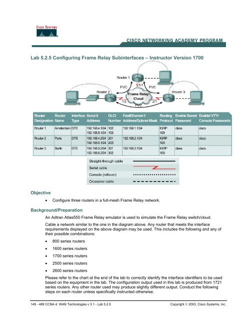
Lab 5.2.5 Configuring Frame Relay Subinterfaces – Instructor Version 1700
Router Interface Summary
Router Interface Summary

Create successful ePaper yourself
Turn your PDF publications into a flip-book with our unique Google optimized e-Paper software.
<strong>Lab</strong> <strong>5.2.5</strong> <strong>Configuring</strong> <strong>Frame</strong> <strong>Relay</strong> <strong>Subinterfaces</strong> <strong>–</strong> <strong>Instructor</strong> <strong>Version</strong> <strong>1700</strong><br />
Objective<br />
• Configure three routers in a full-mesh <strong>Frame</strong> <strong>Relay</strong> network.<br />
Background/Preparation<br />
An Adtran Atlas550 <strong>Frame</strong> <strong>Relay</strong> emulator is used to simulate the <strong>Frame</strong> <strong>Relay</strong> switch/cloud.<br />
Cable a network similar to the one in the diagram above. Any router that meets the interface<br />
requirements displayed on the above diagram may be used. This includes the following and any of<br />
their possible combinations:<br />
• 800 series routers<br />
• 1600 series routers<br />
• <strong>1700</strong> series routers<br />
• 2500 series routers<br />
• 2600 series routers<br />
Please refer to the chart at the end of the lab to correctly identify the interface identifiers to be used<br />
based on the equipment in the lab. The configuration output used in this lab is produced from 1721<br />
series routers. Any other router used may produce slightly different output. Conduct the following<br />
steps on each router unless specifically instructed otherwise.<br />
149 - 489 CCNA 4: WAN Technologies v 3.1 - <strong>Lab</strong> <strong>5.2.5</strong> Copyright © 2003, Cisco Systems, Inc.
Start a HyperTerminal session.<br />
Note: Refer to the erase and reload instructions at the end of this lab. Perform those steps on all<br />
routers in this lab assignment before continuing.<br />
Step 1 Configure the routers<br />
Configure the following according to the chart:<br />
• The hostname<br />
• The console password<br />
• The virtual terminal password<br />
• The enable secret password<br />
• The Fast Ethernet interface according to the chart<br />
If problems occur during this configuration, refer to <strong>Lab</strong> 1.1.4a <strong>Configuring</strong> NAT.<br />
Step 2 Configure the Serial 0 Interfaces<br />
a. First, the <strong>Frame</strong> <strong>Relay</strong> encapsulation type to be used on this link must be defined using the<br />
following commands:<br />
Amsterdam#configure terminal<br />
Amsterdam(config)#interface serial 0<br />
Amsterdam(config-if)#encapsulation frame-relay ietf<br />
Amsterdam(config-if)#frame-relay lmi-type ansi<br />
b. Use a description field to store relevant information, such as the circuit number in case a line<br />
fault has to be reported:<br />
Amsterdam(config-if)#description Circuit #KPN465555<br />
Amsterdam(config-if)#no shutdown<br />
c. The same commands are used to configure the Berlin and Paris routers:<br />
Paris(config)#interface serial 0<br />
Paris(config-if)#encapsulation frame-relay ietf<br />
Paris(config-if)#frame-relay lmi-type ansi<br />
Paris(config-if)#description Circuit #FRT372826<br />
Paris(config-if)#no shutdown<br />
Berlin(config)#interface serial 0<br />
Berlin(config-if)#encapsulation frame-relay ietf<br />
Berlin(config-if)#frame-relay lmi-type ansi<br />
Berlin(config-if)#description Circuit #DTK465866<br />
Berlin(config-if)#no shutdown<br />
150 - 489 CCNA 4: WAN Technologies v 3.1 - <strong>Lab</strong> <strong>5.2.5</strong> Copyright © 2003, Cisco Systems, Inc.
Step 3 Create subinterfaces on the Amsterdam router<br />
For each of the permanent virtual circuits (PVCs), create a subinterface on the serial port. This<br />
subinterface will be a point-to-point configuration. For consistency and future troubleshooting,<br />
use the data-link connection identifier (DLCI) number as the subinterface number. The<br />
commands to create a subinterface are as follows:<br />
Amsterdam(config-if)#interface serial 0.102 point-to-point<br />
Amsterdam(config-if)#description PVC to Paris, DLCI 102, Contact Rick<br />
Voight(+33-1-5534-2234) Circuit #FRT372826<br />
Amsterdam(config-if)#ip address 192.168.4.1 255.255.255.0<br />
Amsterdam(config-if)#frame-relay interface-dlci 102<br />
Amsterdam(config-if)#interface serial 0.103 point-to-point<br />
Amsterdam(config-if)#description PVC to Berlin, DLCI 103, Contact P<br />
Wills(+49- 61 03 / 7 65 72 00) Circuit #DTK465866<br />
Amsterdam(config-if)#ip address 192.168.5.1 255.255.255.0<br />
Amsterdam(config-if)#frame-relay interface-dlci 103<br />
Step 4 Create subinterfaces on the Paris router<br />
To configure the subinterfaces on the Paris router, use the following commands:<br />
Paris(config-if)#interface Serial 0.201 point-to-point<br />
Paris(config-if)#description PVC to Amsterdam, DLCI 201, Contact Peter<br />
Muller (+31 20 623 32 67) Circuit #KPN465555<br />
Paris(config-if)#ip address 192.168.4.2 255.255.255.0<br />
Paris(config-if)#frame-relay interface-dlci 201<br />
Paris(config-if)#interface Serial 0.203 point-to-point<br />
Paris(config-if)#description PVC to Berlin, DLCI 203, Contact Peter<br />
Willis (+49- 61 03 / 7 66 72 00) Circuit #DTK465866<br />
Paris(config-if)#ip address 192.168.6.1 255.255.255.0<br />
Paris(config-if)#frame-relay interface-dlci 203<br />
Step 5 Create subinterfaces on the Berlin router<br />
To configure the subinterfaces on the Berlin router, use the following commands:<br />
Berlin(config-if)#interface Serial 0.301 point-to-point<br />
Berlin(config-if)#description PVC to Amsterdam, DLCI 301, Contact Peter<br />
Muller (+31 20 623 32 67) Circuit #KPN465555<br />
Berlin(config-if)#ip address 192.168.5.2 255.255.255.0<br />
Berlin(config-if)#frame-relay interface-dlci 301<br />
Berlin(config-if)#interface Serial 0.302 point-to-point<br />
Berlin(config-if)#description PVC to Paris, DLCI 302, Contact Rick<br />
Voight (+33-1-5534-2234) Circuit #FRT372826<br />
Berlin(config-if)#ip address 192.168.6.2 255.255.255.0<br />
Berlin(config-if)#frame-relay interface-dlci 302<br />
151 - 489 CCNA 4: WAN Technologies v 3.1 - <strong>Lab</strong> <strong>5.2.5</strong> Copyright © 2003, Cisco Systems, Inc.
Step 6 Configure IGRP routing<br />
To configure the routing protocol Interior Gateway Routing Protocol (IGRP) 100, use the following<br />
configuration syntax:<br />
Amsterdam(config-if)#router igrp 100<br />
Amsterdam(config-router)#network 192.168.1.0<br />
Amsterdam(config-router)#network 192.168.4.0<br />
Amsterdam(config-router)#network 192.168.5.0<br />
Paris(config-if)#router igrp 100<br />
Paris(config-router)#network 192.168.2.0<br />
Paris(config-router)#network 192.168.4.0<br />
Paris(config-router)#network 192.168.6.0<br />
Berlin(config-if)#router igrp 100<br />
Berlin(config-router)#network 192.168.3.0<br />
Berlin(config-router)#network 192.168.5.0<br />
Berlin(config-router)#network 192.168.6.0<br />
Note to instructor: The user should be in the global configuration mode when issuing the<br />
router igrp 100 command. In the online curricuclum, the prompt shows the interface mode,<br />
which is incorrect.<br />
Step 7 Verifying <strong>Frame</strong> <strong>Relay</strong> PVC<br />
a. On the Amsterdam router, issue the command show frame-relay pvc:<br />
Amsterdam#show frame-relay pvc<br />
b. How many active local PVCs are there? 2<br />
c. What is the interface value? Serial0.102, Serial0.103<br />
d. What is the PVC status? Active<br />
e. Which DLCI # is inactive? 104<br />
f. From this it can be seen that there are three DLCIs defined on this <strong>Frame</strong> <strong>Relay</strong> circuit, and only<br />
two of them are in use. This is the way the Adtran 550 emulator has been configured. It is useful<br />
output, as it shows what would be seen if a DLCI is defined on the <strong>Frame</strong> <strong>Relay</strong> switch, but not<br />
configured on the router. The other DLCIs, 102 and 103, are ACTIVE and associated with their<br />
respective subinterfaces. It also shows that some packets have actually passed across the PVC.<br />
Amsterdam#show frame-relay pvc<br />
PVC Statistics for interface Serial0 (<strong>Frame</strong> <strong>Relay</strong> DTE)<br />
Active Inactive Deleted Static<br />
Local 2 1 0 0<br />
Switched 0 0 0 0<br />
Unused 0 0 0 0<br />
DLCI = 102, DLCI USAGE = LOCAL, PVC STATUS = ACTIVE, INTERFACE =<br />
Serial0.102<br />
input pkts 13 output pkts 14 in bytes 2180<br />
out bytes 2254 dropped pkts 0 in pkts dropped 0<br />
out pkts dropped 0 out bytes dropped 0<br />
152 - 489 CCNA 4: WAN Technologies v 3.1 - <strong>Lab</strong> <strong>5.2.5</strong> Copyright © 2003, Cisco Systems, Inc.
in FECN pkts 0 in BECN pkts 0 out FECN pkts 0<br />
out BECN pkts 0 in DE pkts 0 out DE pkts 0<br />
out bcast pkts 14 out bcast bytes 2254<br />
pvc create time 00:14:27, last time pvc status changed 00:02:59<br />
DLCI = 103, DLCI USAGE = LOCAL, PVC STATUS = ACTIVE, INTERFACE =<br />
Serial0.103<br />
input pkts 16 output pkts 14 in bytes 2258<br />
out bytes 2307 dropped pkts 0 in pkts dropped 0<br />
out pkts dropped 0 out bytes dropped 0<br />
in FECN pkts 0 in BECN pkts 0 out FECN pkts 0<br />
out BECN pkts 0 in DE pkts 0 out DE pkts 0<br />
out bcast pkts 9 out bcast bytes 1787<br />
pvc create time 00:14:29, last time pvc status changed 00:02:02<br />
DLCI = 104, DLCI USAGE = LOCAL, PVC STATUS = INACTIVE, INTERFACE =<br />
Serial0<br />
input pkts 0 output pkts 0 in bytes 0<br />
out bytes 0 dropped pkts 0 in pkts dropped 0<br />
out pkts dropped 0 out bytes dropped 0<br />
in FECN pkts 0 in BECN pkts 0 out FECN pkts 0<br />
out BECN pkts 0 in DE pkts 0 out DE pkts 0<br />
out bcast pkts 0 out bcast bytes 0<br />
pvc create time 00:14:30, last time pvc status changed 00:06:13<br />
Step 8 Show the <strong>Frame</strong> <strong>Relay</strong> maps<br />
a. Look at the frame relay maps by typing the command show frame-relay map at the<br />
privileged EXEC mode prompt:<br />
Amsterdam#show frame-relay map<br />
b. What is the status of the links? Up<br />
c. The DLCIs are defined as what type? Point-to-Point<br />
d. Are the DLCIs the same on the Paris router? No<br />
Amsterdam#show frame-relay map<br />
Serial0.103 (up): point-to-point dlci, dlci 103(0x67,0x1870), broadcast<br />
status defined, active<br />
Serial0.102 (up): point-to-point dlci, dlci 102(0x66,0x1860), broadcast<br />
status defined, active<br />
Step 9 Show LMIs<br />
a. Look at the Local Management Interface (LMI) statistics using the show frame-relay lmi<br />
command:<br />
Amsterdam#show frame-relay lmi<br />
b. Which fields have non-zero counter values? Num Status Enq. Sent, Num Status msgs Rcvd<br />
c. What is the LMI type? ANSI<br />
Amsterdam#show frame-relay lmi<br />
LMI Statistics for interface Serial0 (<strong>Frame</strong> <strong>Relay</strong> DTE) LMI TYPE = ANSI<br />
153 - 489 CCNA 4: WAN Technologies v 3.1 - <strong>Lab</strong> <strong>5.2.5</strong> Copyright © 2003, Cisco Systems, Inc.
Invalid Unnumbered info 0 Invalid Prot Disc 0<br />
Invalid dummy Call Ref 0 Invalid Msg Type 0<br />
Invalid Status Message 0 Invalid Lock Shift 0<br />
Invalid Information ID 0 Invalid Report IE Len 0<br />
Invalid Report Request 0 Invalid Keep IE Len 0<br />
Num Status Enq. Sent 55 Num Status msgs Rcvd 56<br />
Num Update Status Rcvd 0 Num Status Timeouts 0<br />
Step 10 Check routing protocol<br />
a. Use the show ip route command to verify that the PVCs are up and active:<br />
Amsterdam#show ip route<br />
b. Is the routing protocol working? Yes<br />
c. If not, troubleshoot the routers configurations.<br />
List the IGRP routes<br />
I 192.168.6.0/24 [100/10476] via 192.168.4.2, 00:01:06, Serial0.102<br />
[100/10476] via 192.168.5.2, 00:01:20, Serial0.103<br />
I 192.168.2.0/24 [100/8486] via 192.168.4.2, 00:01:06, Serial0.102<br />
I 192.168.3.0/24 [100/8486] via 192.168.5.2, 00:01:20, Serial0.103<br />
Amsterdam#show ip route<br />
Codes: C - connected, S - static, I - IGRP, R - RIP, M - mobile, B <strong>–</strong><br />
BGP<br />
D - EIGRP, EX - EIGRP external, O - OSPF, IA - OSPF inter area<br />
N1 - OSPF NSSA external type 1, N2 - OSPF NSSA external type 2<br />
E1 - OSPF external type 1, E2 - OSPF external type 2, E - EGP<br />
i - IS-IS, L1 - IS-IS level-1, L2 - IS-IS level-2, ia - IS-IS<br />
inter area<br />
* - candidate default, U - per-user static route, o - ODR<br />
P - periodic downloaded static route<br />
Gateway of last resort is not set<br />
C<br />
C<br />
I<br />
C<br />
I<br />
I<br />
192.168.4.0/24 is directly connected, Serial0.102<br />
192.168.5.0/24 is directly connected, Serial0.103<br />
192.168.6.0/24 [100/10476] via 192.168.4.2, 00:01:06, Serial0.102<br />
[100/10476] via 192.168.5.2, 00:01:20, Serial0.103<br />
192.168.1.0/24 is directly connected, FastEthernet0<br />
192.168.2.0/24 [100/8486] via 192.168.4.2, 00:01:06, Serial0.102<br />
192.168.3.0/24 [100/8486] via 192.168.5.2, 00:01:20, Serial0.103<br />
Step 11 Verify connectivity<br />
a. Ping the fastethernet interfaces.<br />
b. Were the pings successful? Yes<br />
c. If the pings were not successful, troubleshoot the router configurations and repeat this step.<br />
Amsterdam#ping 192.168.1.1<br />
Type escape sequence to abort.<br />
Sending 5, 100-byte ICMP Echos to 192.168.1.1, timeout is 2 seconds:<br />
!!!!!<br />
Success rate is 100 percent (5/5), round-trip min/avg/max = 1/1/4 ms<br />
Amsterdam#ping 192.168.2.1<br />
Type escape sequence to abort.<br />
154 - 489 CCNA 4: WAN Technologies v 3.1 - <strong>Lab</strong> <strong>5.2.5</strong> Copyright © 2003, Cisco Systems, Inc.
Sending 5, 100-byte ICMP Echos to 192.168.2.1, timeout is 2 seconds:<br />
!!!!!<br />
Success rate is 100 percent (5/5), round-trip min/avg/max = 36/39/40 ms<br />
Amsterdam#ping 192.168.3.1<br />
Type escape sequence to abort.<br />
Sending 5, 100-byte ICMP Echos to 192.168.3.1, timeout is 2 seconds:<br />
!!!!!<br />
Success rate is 100 percent (5/5), round-trip min/avg/max = 40/40/40 ms<br />
Upon completion of the previous steps, finish the lab by doing the following:<br />
• Logoff by typing exit<br />
• Turn the router off<br />
• Remove and store the cables and adapter<br />
155 - 489 CCNA 4: WAN Technologies v 3.1 - <strong>Lab</strong> <strong>5.2.5</strong> Copyright © 2003, Cisco Systems, Inc.
Amsterdam<br />
Router#configure terminal<br />
Router(config)#hostname Amsterdam<br />
Amsterdam(config)#enable password cisco<br />
Amsterdam(config)#enable secret class<br />
Amsterdam(config)#line con 0<br />
Amsterdam(config-line)#password cisco<br />
Amsterdam(config-line)#login<br />
Amsterdam(config-line)#line vty 0 4<br />
Amsterdam(config-line)#password cisco<br />
Amsterdam(config-line)#login<br />
Amsterdam(config-line)#interface fastethernet 0<br />
Amsterdam(config-if)#ip address 192.168.1.1 255.255.255.0<br />
Amsterdam(config-if)#no shutdown<br />
Amsterdam(config-if)#exit<br />
Amsterdam(config)#exit<br />
Amsterdam#copy running-config startup-config<br />
Amsterdam <strong>Frame</strong> <strong>Relay</strong> and IGRP Configuration<br />
Amsterdam#configure terminal<br />
Amsterdam(config)#interface serial 0<br />
Amsterdam(config-if)#encapsulation frame-relay ietf<br />
Amsterdam(config-if)#frame-relay lmi-type ansi<br />
Amsterdam(config-if)#description Circuit #KPN465555<br />
Amsterdam(config-if)#no shutdown<br />
Amsterdam(config-if)#interface serial 0.102 point-to-point<br />
Amsterdam(config-subif)#description PVC to Paris, DLCI 102, contact Rick<br />
Voight(+33-1-5534-2234) Circuit #FRT372826<br />
Amsterdam(config-subif)#ip address 192.168.4.1 255.255.255.0<br />
Amsterdam(config-subif)#frame-relay interface-dlci 102<br />
Amsterdam(config-fr-dlci)#interface serial 0.103 point-to-point<br />
Amsterdam(config-subif)#description PVC to Berlin, DLCI 103, Contact P<br />
Wills (+49- 61 03 / 7 65 72 00) Circuit #DTK465866<br />
Amsterdam(config-subif)#ip address 192.168.5.1 255.255.255.0<br />
Amsterdam(config-subif)#frame-relay interface-dlci 103<br />
Amsterdam(config-fr-dlci)#router igrp 100<br />
Amsterdam(config-router)#network 192.168.1.0<br />
Amsterdam(config-router)#network 192.168.4.0<br />
Amsterdam(config-router)#network 192.168.5.0<br />
Amsterdam(config-router)#exit<br />
Amsterdam(config)#exit<br />
Amsterdam#copy running-config startup-config<br />
Paris<br />
Router#configure terminal<br />
Router(config)#hostname Paris<br />
Paris(config)#enable password cisco<br />
Paris(config)#enable secret class<br />
Paris(config)#line con 0<br />
Paris(config-line)#password cisco<br />
Paris(config-line)#login<br />
Paris(config-line)#line vty 0 4<br />
Paris(config-line)#password cisco<br />
Paris(config-line)#login<br />
Paris(config-line)#interface fastethernet 0<br />
Paris(config-if)#ip address 192.168.2.1 255.255.255.0<br />
Paris(config-if)#no shutdown<br />
Paris(config-if)#exit<br />
156 - 489 CCNA 4: WAN Technologies v 3.1 - <strong>Lab</strong> <strong>5.2.5</strong> Copyright © 2003, Cisco Systems, Inc.
Paris(config)#exit<br />
Paris#copy running-config startup-config<br />
Paris <strong>Frame</strong> <strong>Relay</strong> and IGRP Configuration<br />
Paris#configure terminal<br />
Paris(config)#interface serial 0<br />
Paris(config-if)#encapsulation frame-relay ietf<br />
Paris(config-if)#frame-relay lmi-type ansi<br />
Paris(config-if)#description Circuit #FRT372826<br />
Paris(config-if)#no shutdown<br />
Paris(config-if)#interface Serial 0.201 point-to-point<br />
Paris(config-subif)#description PVC to Amsterdam, DLCI 201, Contact Peter<br />
Muller (+31 20 623 32 67) Circuit #KPN465555<br />
Paris(config-subif)#ip address 192.168.4.2 255.255.255.0<br />
Paris(config-subif)#frame-relay interface-dlci 201<br />
Paris(config-fr-dlci)#interface Serial 0.203 point-to-point<br />
Paris(config-subif)#description PVC to Berlin, DLCI 203, Contact Peter<br />
Willis (+49- 61 03 / 7 66 72 00) Circuit #DTK465866<br />
Paris(config-subif)#ip address 192.168.6.1 255.255.255.0<br />
Paris(config-subif)#frame-relay interface-dlci 203<br />
Paris(config-fr-dlci)#router igrp 100<br />
Paris(config-router)#network 192.168.2.0<br />
Paris(config-router)#network 192.168.4.0<br />
Paris(config-router)#network 192.168.6.0<br />
Paris(config-router)#exit<br />
Paris(config)#exit<br />
Paris#copy running-config startup-config<br />
Berlin<br />
Router#configure terminal<br />
Router(config)#hostname Berlin<br />
Berlin(config)#enable password cisco<br />
Berlin(config)#enable secret class<br />
Berlin(config)#line con 0<br />
Berlin(config-line)#password cisco<br />
Berlin(config-line)#login<br />
Berlin(config-line)#line vty 0 4<br />
Berlin(config-line)#password cisco<br />
Berlin(config-line)#login<br />
Berlin(config-line)#interface fastethernet 0<br />
Berlin(config-if)#ip address 192.168.3.1 255.255.255.0<br />
Berlin(config-if)#no shutdown<br />
Berlin(config-if)#exit<br />
Berlin(config)#exit<br />
Berlin#copy running-config startup-config<br />
Berlin <strong>Frame</strong> <strong>Relay</strong> and IGRP Configuration<br />
Berlin#configure terminal<br />
Enter configuration commands, one per line. End with CNTL/Z.<br />
Berlin(config)#interface serial 0<br />
Berlin(config-if)#encapsulation frame-relay ietf<br />
Berlin(config-if)#frame-relay lmi-type ansi<br />
Berlin(config-if)#description Circuit #DTK465866<br />
Berlin(config-if)#no shutdown<br />
Berlin(config-if)#interface Serial 0.301 point-to-point<br />
157 - 489 CCNA 4: WAN Technologies v 3.1 - <strong>Lab</strong> <strong>5.2.5</strong> Copyright © 2003, Cisco Systems, Inc.
Berlin(config-subif)#description PVC to Amsterdam, DLCI 301, Contact Peter<br />
Muller (+31 20 623 32 67) Circuit #KPN465555<br />
Berlin(config-subif)#ip address 192.168.5.2 255.255.255.0<br />
Berlin(config-subif)#frame-relay interface-dlci 301<br />
Berlin(config-fr-dlci)#interface Serial 0.302 point-to-point<br />
Berlin(config-subif)#$ description PVC to Paris, DLCI 302, Contact Rick<br />
Voight (+33-1-5534-2234) Circuit #FRT372826<br />
Berlin(config-subif)#ip address 192.168.6.2 255.255.255.0<br />
Berlin(config-subif)#frame-relay interface-dlci 302<br />
Berlin(config-subif)#exit<br />
Berlin(config-if)#exit<br />
Berlin(config)#router igrp 100<br />
Berlin(config-router)#network 192.168.3.0<br />
Berlin(config-router)#network 192.168.5.0<br />
Berlin(config-router)#network 192.168.6.0<br />
Berlin(config-router)#exit<br />
Berlin(config)#exit<br />
Berlin#copy running-config startup-config<br />
158 - 489 CCNA 4: WAN Technologies v 3.1 - <strong>Lab</strong> <strong>5.2.5</strong> Copyright © 2003, Cisco Systems, Inc.
Erasing and reloading the router<br />
Enter into the privileged EXEC mode by typing enable.<br />
If prompted for a password, enter class (if that does not work, ask the instructor).<br />
Router>enable<br />
At the privileged EXEC mode, enter the command erase startup-config.<br />
Router#erase startup-config<br />
The responding line prompt will be:<br />
Erasing the nvram filesystem will remove all files! Continue? [confirm]<br />
Press Enter to confirm.<br />
The response should be:<br />
Erase of nvram: complete<br />
Now at the privileged EXEC mode, enter the command reload.<br />
Router(config)#reload<br />
The responding line prompt will be:<br />
System configuration has been modified. Save? [yes/no]:<br />
Type n and then press Enter.<br />
The responding line prompt will be:<br />
Proceed with reload? [confirm]<br />
Press Enter to confirm.<br />
In the first line of the response will be:<br />
Reload requested by console.<br />
After the router has reloaded the line prompt will be:<br />
Would you like to enter the initial configuration dialog? [yes/no]:<br />
Type n and then press Enter.<br />
The responding line prompt will be:<br />
Press RETURN to get started!<br />
Press Enter.<br />
Now the router is ready for the assigned lab to be performed.<br />
159 - 489 CCNA 4: WAN Technologies v 3.1 - <strong>Lab</strong> <strong>5.2.5</strong> Copyright © 2003, Cisco Systems, Inc.
Router Interface Summary<br />
Router<br />
Model<br />
Ethernet<br />
Interface #1<br />
Ethernet<br />
Interface #2<br />
Serial<br />
Interface #1<br />
Serial<br />
Interface #2<br />
800 (806) Ethernet 0 (E0) Ethernet 1 (E1)<br />
1600 Ethernet 0 (E0) Ethernet 1 (E1) Serial 0 (S0) Serial 1 (S1)<br />
<strong>1700</strong> FastEthernet 0 (FA0) FastEthernet 1 (FA1) Serial 0 (S0) Serial 1 (S1)<br />
2500 Ethernet 0 (E0) Ethernet 1 (E1) Serial 0 (S0) Serial 1 (S1)<br />
2600 FastEthernet 0/0 (FA0/0) FastEthernet 0/1 (FA0/1) Serial 0/0 (S0/0) Serial 0/1 (S0/1)<br />
In order to find out exactly how the router is configured, look at the interfaces. This will identify what type and how<br />
many interfaces the router has. There is no way to effectively list all of the combinations of configurations for each<br />
router class. What is provided are the identifiers for the possible combinations of interfaces in the device. This<br />
interface chart does not include any other type of interface even though a specific router may contain one. An<br />
example of this might be an ISDN BRI interface. The string in parenthesis is the legal abbreviation that can be<br />
used in an IOS command to represent the interface.<br />
160 - 489 CCNA 4: WAN Technologies v 3.1 - <strong>Lab</strong> <strong>5.2.5</strong> Copyright © 2003, Cisco Systems, Inc.
<strong>Lab</strong> <strong>5.2.5</strong> <strong>Configuring</strong> <strong>Frame</strong> <strong>Relay</strong> <strong>Subinterfaces</strong> <strong>–</strong> <strong>Instructor</strong> <strong>Version</strong> 2500<br />
Objective<br />
• Configure three routers in a full-mesh <strong>Frame</strong> <strong>Relay</strong> network.<br />
Background/Preparation<br />
An Adtran Atlas550 <strong>Frame</strong> <strong>Relay</strong> emulator is used to simulate the <strong>Frame</strong> <strong>Relay</strong> switch/cloud.<br />
Cable a network similar to the one in the diagram above. Any router that meets the interface<br />
requirements displayed on the above diagram may be used. This includes the following and any of<br />
their possible combinations:<br />
• 800 series routers<br />
• 1600 series routers<br />
• <strong>1700</strong> series routers<br />
• 2500 series routers<br />
• 2600 series routers<br />
Please refer to the chart at the end of the lab to correctly identify the interface identifiers to be used<br />
based on the equipment in the lab. The configuration output used in this lab is produced from 1721<br />
series routers. Any other router used may produce slightly different output. Conduct the following<br />
steps on each router unless specifically instructed otherwise.<br />
314 - 489 CCNA 4: WAN Technologies v 3.1 - <strong>Lab</strong> <strong>5.2.5</strong> Copyright © 2003, Cisco Systems, Inc.
Start a HyperTerminal session.<br />
Note: Refer to the erase and reload instructions at the end of this lab. Perform those steps on all<br />
routers in this lab assignment before continuing.<br />
Step 1 Configure the routers<br />
Configure the following according to the chart:<br />
• The hostname<br />
• The console password<br />
• The virtual terminal password<br />
• The enable secret password<br />
• The Fast Ethernet interface according to the chart<br />
If problems occur during this configuration, refer to <strong>Lab</strong> 1.1.4a <strong>Configuring</strong> NAT.<br />
Step 2 Configure the Serial 0 Interfaces<br />
a. First, the <strong>Frame</strong> <strong>Relay</strong> encapsulation type to be used on this link must be defined using the<br />
following commands:<br />
Amsterdam#configure terminal<br />
Amsterdam(config)#interface serial 0<br />
Amsterdam(config-if)#encapsulation frame-relay ietf<br />
Amsterdam(config-if)#frame-relay lmi-type ansi<br />
b. Use a description field to store relevant information, such as the circuit number in case a line<br />
fault has to be reported:<br />
Amsterdam(config-if)#description Circuit #KPN465555<br />
Amsterdam(config-if)#no shutdown<br />
c. The same commands are used to configure the Berlin and Paris routers:<br />
Paris(config)#interface serial 0<br />
Paris(config-if)#encapsulation frame-relay ietf<br />
Paris(config-if)#frame-relay lmi-type ansi<br />
Paris(config-if)#description Circuit #FRT372826<br />
Paris(config-if)#no shutdown<br />
Berlin(config)#interface serial 0<br />
Berlin(config-if)#encapsulation frame-relay ietf<br />
Berlin(config-if)#frame-relay lmi-type ansi<br />
Berlin(config-if)#description Circuit #DTK465866<br />
Berlin(config-if)#no shutdown<br />
315 - 489 CCNA 4: WAN Technologies v 3.1 - <strong>Lab</strong> <strong>5.2.5</strong> Copyright © 2003, Cisco Systems, Inc.
Step 3 Create subinterfaces on the Amsterdam router<br />
For each of the permanent virtual circuits (PVCs), create a subinterface on the serial port. This<br />
subinterface will be a point-to-point configuration. For consistency and future troubleshooting,<br />
use the data-link connection identifier (DLCI) number as the subinterface number. The<br />
commands to create a subinterface are as follows:<br />
Amsterdam(config-if)#interface serial 0.102 point-to-point<br />
Amsterdam(config-if)#description PVC to Paris, DLCI 102, Contact Rick<br />
Voight(+33-1-5534-2234) Circuit #FRT372826<br />
Amsterdam(config-if)#ip address 192.168.4.1 255.255.255.0<br />
Amsterdam(config-if)#frame-relay interface-dlci 102<br />
Amsterdam(config-if)#interface serial 0.103 point-to-point<br />
Amsterdam(config-if)#description PVC to Berlin, DLCI 103, Contact P<br />
Wills(+49- 61 03 / 7 65 72 00) Circuit #DTK465866<br />
Amsterdam(config-if)#ip address 192.168.5.1 255.255.255.0<br />
Amsterdam(config-if)#frame-relay interface-dlci 103<br />
Step 4 Create subinterfaces on the Paris router<br />
To configure the subinterfaces on the Paris router, use the following commands:<br />
Paris(config-if)#interface Serial 0.201 point-to-point<br />
Paris(config-if)#description PVC to Amsterdam, DLCI 201, Contact Peter<br />
Muller (+31 20 623 32 67) Circuit #KPN465555<br />
Paris(config-if)#ip address 192.168.4.2 255.255.255.0<br />
Paris(config-if)#frame-relay interface-dlci 201<br />
Paris(config-if)#interface Serial 0.203 point-to-point<br />
Paris(config-if)#description PVC to Berlin, DLCI 203, Contact Peter<br />
Willis (+49- 61 03 / 7 66 72 00) Circuit #DTK465866<br />
Paris(config-if)#ip address 192.168.6.1 255.255.255.0<br />
Paris(config-if)#frame-relay interface-dlci 203<br />
Step 5 Create subinterfaces on the Berlin router<br />
To configure the subinterfaces on the Berlin router, use the following commands:<br />
Berlin(config-if)#interface Serial 0.301 point-to-point<br />
Berlin(config-if)#description PVC to Amsterdam, DLCI 301, Contact Peter<br />
Muller (+31 20 623 32 67) Circuit #KPN465555<br />
Berlin(config-if)#ip address 192.168.5.2 255.255.255.0<br />
Berlin(config-if)#frame-relay interface-dlci 301<br />
Berlin(config-if)#interface Serial 0.302 point-to-point<br />
Berlin(config-if)#description PVC to Paris, DLCI 302, Contact Rick<br />
Voight (+33-1-5534-2234) Circuit #FRT372826<br />
Berlin(config-if)#ip address 192.168.6.2 255.255.255.0<br />
Berlin(config-if)#frame-relay interface-dlci 302<br />
316 - 489 CCNA 4: WAN Technologies v 3.1 - <strong>Lab</strong> <strong>5.2.5</strong> Copyright © 2003, Cisco Systems, Inc.
Step 6 Configure IGRP routing<br />
To configure the routing protocol Interior Gateway Routing Protocol (IGRP) 100, use the following<br />
configuration syntax:<br />
Amsterdam(config-if)#router igrp 100<br />
Amsterdam(config-router)#network 192.168.1.0<br />
Amsterdam(config-router)#network 192.168.4.0<br />
Amsterdam(config-router)#network 192.168.5.0<br />
Paris(config-if)#router igrp 100<br />
Paris(config-router)#network 192.168.2.0<br />
Paris(config-router)#network 192.168.4.0<br />
Paris(config-router)#network 192.168.6.0<br />
Berlin(config-if)#router igrp 100<br />
Berlin(config-router)#network 192.168.3.0<br />
Berlin(config-router)#network 192.168.5.0<br />
Berlin(config-router)#network 192.168.6.0<br />
Step 7 Verifying <strong>Frame</strong> <strong>Relay</strong> PVC<br />
a. On the Amsterdam router, issue the command show frame-relay pvc:<br />
Amsterdam#show frame-relay pvc<br />
b. How many active local PVCs are there? 2<br />
c. What is the interface value? Serial0.102, Serial0.103<br />
d. What is the PVC status? Active<br />
e. Which DLCI # is inactive? 104<br />
f. From this it can be seen that there are three DLCIs defined on this <strong>Frame</strong> <strong>Relay</strong> circuit, and only<br />
two of them are in use. This is the way the Adtran 550 emulator has been configured. It is useful<br />
output, as it shows what would be seen if a DLCI is defined on the <strong>Frame</strong> <strong>Relay</strong> switch, but not<br />
configured on the router. The other DLCIs, 102 and 103, are ACTIVE and associated with their<br />
respective subinterfaces. It also shows that some packets have actually passed across the PVC.<br />
Amsterdam#show frame-relay pvc<br />
PVC Statistics for interface Serial0 (<strong>Frame</strong> <strong>Relay</strong> DTE)<br />
Active Inactive Deleted Static<br />
Local 2 1 0 0<br />
Switched 0 0 0 0<br />
Unused 0 0 0 0<br />
DLCI = 102, DLCI USAGE = LOCAL, PVC STATUS = ACTIVE, INTERFACE =<br />
Serial0.102<br />
input pkts 13 output pkts 14 in bytes 2180<br />
out bytes 2254 dropped pkts 0 in pkts dropped 0<br />
out pkts dropped 0 out bytes dropped 0<br />
in FECN pkts 0 in BECN pkts 0 out FECN pkts 0<br />
out BECN pkts 0 in DE pkts 0 out DE pkts 0<br />
out bcast pkts 14 out bcast bytes 2254<br />
pvc create time 00:14:27, last time pvc status changed 00:02:59<br />
317 - 489 CCNA 4: WAN Technologies v 3.1 - <strong>Lab</strong> <strong>5.2.5</strong> Copyright © 2003, Cisco Systems, Inc.
DLCI = 103, DLCI USAGE = LOCAL, PVC STATUS = ACTIVE, INTERFACE =<br />
Serial0.103<br />
input pkts 16 output pkts 14 in bytes 2258<br />
out bytes 2307 dropped pkts 0 in pkts dropped 0<br />
out pkts dropped 0 out bytes dropped 0<br />
in FECN pkts 0 in BECN pkts 0 out FECN pkts 0<br />
out BECN pkts 0 in DE pkts 0 out DE pkts 0<br />
out bcast pkts 9 out bcast bytes 1787<br />
pvc create time 00:14:29, last time pvc status changed 00:02:02<br />
Step 8 Show the <strong>Frame</strong> <strong>Relay</strong> maps<br />
a. Look at the frame relay maps by typing the command show frame-relay map at the<br />
privileged EXEC mode prompt:<br />
Amsterdam#show frame-relay map<br />
b. What is the status of the links? Up<br />
c. The DLCIs are defined as what type? Point-to-Point<br />
d. Are the DLCIs the same on the Paris router? No<br />
Amsterdam#show frame-relay map<br />
Serial0.103 (up): point-to-point dlci, dlci 103(0x67,0x1870), broadcast<br />
status defined, active<br />
Serial0.102 (up): point-to-point dlci, dlci 102(0x66,0x1860), broadcast<br />
status defined, active<br />
Step 9 Show LMIs<br />
a. Look at the Local Management Interface (LMI) statistics using the show frame-relay lmi<br />
command:<br />
Amsterdam#show frame-relay lmi<br />
b. Which fields have non-zero counter values? Num Status Enq. Sent, Num Status msgs Rcvd<br />
c. What is the LMI type? ANSI<br />
Amsterdam#show frame-relay lmi<br />
LMI Statistics for interface Serial0 (<strong>Frame</strong> <strong>Relay</strong> DTE) LMI TYPE = ANSI<br />
Invalid Unnumbered info 0 Invalid Prot Disc 0<br />
Invalid dummy Call Ref 0 Invalid Msg Type 0<br />
Invalid Status Message 0 Invalid Lock Shift 0<br />
Invalid Information ID 0 Invalid Report IE Len 0<br />
Invalid Report Request 0 Invalid Keep IE Len 0<br />
Num Status Enq. Sent 55 Num Status msgs Rcvd 56<br />
Num Update Status Rcvd 0 Num Status Timeouts 0<br />
Step 10 Check routing protocol<br />
a. Use the show ip route command to verify that the PVCs are up and active:<br />
Amsterdam#show ip route<br />
318 - 489 CCNA 4: WAN Technologies v 3.1 - <strong>Lab</strong> <strong>5.2.5</strong> Copyright © 2003, Cisco Systems, Inc.
. Is the routing protocol working? Yes<br />
c. If not, troubleshoot the routers configurations.<br />
d. List the IGRP routes<br />
I 192.168.6.0/24 [100/10476] via 192.168.4.2, 00:01:06, Serial0.102<br />
[100/10476] via 192.168.5.2, 00:01:20, Serial0.103<br />
I 192.168.2.0/24 [100/8486] via 192.168.4.2, 00:01:06, Serial0.102<br />
I 192.168.3.0/24 [100/8486] via 192.168.5.2, 00:01:20, Serial0.103<br />
Amsterdam#show ip route<br />
Codes: C - connected, S - static, I - IGRP, R - RIP, M - mobile, B <strong>–</strong><br />
BGP<br />
D - EIGRP, EX - EIGRP external, O - OSPF, IA - OSPF inter area<br />
N1 - OSPF NSSA external type 1, N2 - OSPF NSSA external type 2<br />
E1 - OSPF external type 1, E2 - OSPF external type 2, E - EGP<br />
i - IS-IS, L1 - IS-IS level-1, L2 - IS-IS level-2, ia - IS-IS<br />
inter area<br />
* - candidate default, U - per-user static route, o - ODR<br />
P - periodic downloaded static route<br />
Gateway of last resort is not set<br />
C<br />
C<br />
I<br />
C<br />
I<br />
I<br />
192.168.4.0/24 is directly connected, Serial0.102<br />
192.168.5.0/24 is directly connected, Serial0.103<br />
192.168.6.0/24 [100/10476] via 192.168.4.2, 00:01:06, Serial0.102<br />
[100/10476] via 192.168.5.2, 00:01:20, Serial0.103<br />
192.168.1.0/24 is directly connected, Ethernet0<br />
192.168.2.0/24 [100/8486] via 192.168.4.2, 00:01:06, Serial0.102<br />
192.168.3.0/24 [100/8486] via 192.168.5.2, 00:01:20, Serial0.103<br />
Step 11 Verify connectivity<br />
a. Ping the fastethernet interfaces.<br />
b. Were the pings successful? Yes<br />
c. If the pings were not successful, troubleshoot the router configurations and repeat this step.<br />
Amsterdam#ping 192.168.1.1<br />
Type escape sequence to abort.<br />
Sending 5, 100-byte ICMP Echos to 192.168.1.1, timeout is 2 seconds:<br />
!!!!!<br />
Success rate is 100 percent (5/5), round-trip min/avg/max = 1/1/4 ms<br />
Amsterdam#ping 192.168.2.1<br />
Type escape sequence to abort.<br />
Sending 5, 100-byte ICMP Echos to 192.168.2.1, timeout is 2 seconds:<br />
!!!!!<br />
Success rate is 100 percent (5/5), round-trip min/avg/max = 36/39/40 ms<br />
Amsterdam#ping 192.168.3.1<br />
Type escape sequence to abort.<br />
Sending 5, 100-byte ICMP Echos to 192.168.3.1, timeout is 2 seconds:<br />
!!!!!<br />
Success rate is 100 percent (5/5), round-trip min/avg/max = 40/40/40 ms<br />
Upon completion of the previous steps, finish the lab by doing the following:<br />
• Logoff by typing exit<br />
319 - 489 CCNA 4: WAN Technologies v 3.1 - <strong>Lab</strong> <strong>5.2.5</strong> Copyright © 2003, Cisco Systems, Inc.
• Turn the router off<br />
• Remove and store the cables and adapter<br />
320 - 489 CCNA 4: WAN Technologies v 3.1 - <strong>Lab</strong> <strong>5.2.5</strong> Copyright © 2003, Cisco Systems, Inc.
Amsterdam<br />
Router#configure terminal<br />
Router(config)#hostname Amsterdam<br />
Amsterdam(config)#enable password cisco<br />
Amsterdam(config)#enable secret class<br />
Amsterdam(config)#line console 0<br />
Amsterdam(config-line)#password cisco<br />
Amsterdam(config-line)#login<br />
Amsterdam(config-line)#line vty 0 4<br />
Amsterdam(config-line)#password cisco<br />
Amsterdam(config-line)#login<br />
Amsterdam(config-line)#exit<br />
Amsterdam(config-line)#interface ethernet 0<br />
Amsterdam(config-if)#ip address 192.168.1.1 255.255.255.0<br />
Amsterdam(config-if)#no shutdown<br />
Amsterdam(config-if)#exit<br />
Amsterdam(config)#exit<br />
Amsterdam#copy running-config startup-config<br />
Amsterdam <strong>Frame</strong> <strong>Relay</strong> and IGRP Configuration<br />
Amsterdam#configure terminal<br />
Amsterdam(config)#interface serial 0<br />
Amsterdam(config-if)#encapsulation frame-relay ietf<br />
Amsterdam(config-if)#frame-relay lmi-type ansi<br />
Amsterdam(config-if)#description Circuit #KPN465555<br />
Amsterdam(config-if)#no shutdown<br />
Amsterdam(config-if)#interface serial 0.102 point-to-point<br />
Amsterdam(config-subif)#description PVC to Paris, DLCI 102, contact Rick<br />
Voight(+33-1-5534-2234) Circuit #FRT372826<br />
Amsterdam(config-subif)#ip address 192.168.4.1 255.255.255.0<br />
Amsterdam(config-subif)#frame-relay interface-dlci 102<br />
Amsterdam(config-fr-dlci)#interface serial 0.103 point-to-point<br />
Amsterdam(config-subif)#description PVC to Berlin, DLCI 103, Contact P<br />
Wills (+49- 61 03 / 7 65 72 00) Circuit #DTK465866<br />
Amsterdam(config-subif)#ip address 192.168.5.1 255.255.255.0<br />
Amsterdam(config-subif)#frame-relay interface-dlci 103<br />
Amsterdam(config-fr-dlci)#router igrp 100<br />
Amsterdam(config-router)#network 192.168.1.0<br />
Amsterdam(config-router)#network 192.168.4.0<br />
Amsterdam(config-router)#network 192.168.5.0<br />
Amsterdam(config-router)#exit<br />
Amsterdam(config)#exit<br />
Amsterdam#copy running-config startup-config<br />
Paris<br />
Router#configure terminal<br />
Router(config)#hostname Paris<br />
Paris(config)#enable password cisco<br />
Paris(config)#enable secret class<br />
Paris(config)#line console 0<br />
Paris(config-line)#password cisco<br />
Paris(config-line)#login<br />
Paris(config-line)#exit<br />
Paris(config)#line vty 0 4<br />
Paris(config-line)#password cisco<br />
Paris(config-line)#login<br />
Paris(config-line)#exit<br />
Paris(config)#interface ethernet 0<br />
321 - 489 CCNA 4: WAN Technologies v 3.1 - <strong>Lab</strong> <strong>5.2.5</strong> Copyright © 2003, Cisco Systems, Inc.
Paris(config-if)#ip address 192.168.2.1 255.255.255.0<br />
Paris(config-if)#no shutdown<br />
Paris(config-if)#exit<br />
Paris(config)#exit<br />
Paris#copy running-config startup-config<br />
Paris <strong>Frame</strong> <strong>Relay</strong> and IGRP Configuration<br />
Paris#configure terminal<br />
Paris(config)#interface serial 0<br />
Paris(config-if)#encapsulation frame-relay ietf<br />
Paris(config-if)#frame-relay lmi-type ansi<br />
Paris(config-if)#description Circuit #FRT372826<br />
Paris(config-if)#no shutdown<br />
Paris(config-if)#exit<br />
Paris(config)#interface Serial 0.201 point-to-point<br />
Paris(config-subif)#description PVC to Amsterdam, DLCI 201, Contact Peter<br />
Muller (+31 20 623 32 67) Circuit #KPN465555<br />
Paris(config-subif)#ip address 192.168.4.2 255.255.255.0<br />
Paris(config-subif)#frame-relay interface-dlci 201<br />
Paris(config-fr-dlci)#interface Serial 0.203 point-to-point<br />
Paris(config-subif)#description PVC to Berlin, DLCI 203, Contact Peter<br />
Willis (+49- 61 03 / 7 66 72 00) Circuit #DTK465866<br />
Paris(config-subif)#ip address 192.168.6.1 255.255.255.0<br />
Paris(config-subif)#frame-relay interface-dlci 203<br />
Paris(config-subif)#exit<br />
Paris(config-if)#exit<br />
Paris(config)#exit<br />
Paris(config)#router igrp 100<br />
Paris(config-router)#network 192.168.2.0<br />
Paris(config-router)#network 192.168.4.0<br />
Paris(config-router)#network 192.168.6.0<br />
Paris(config-router)#exit<br />
Paris(config)#exit<br />
Paris#copy running-config startup-config<br />
Berlin<br />
Router#configure terminal<br />
Router(config)#hostname Berlin<br />
Berlin(config)#enable password cisco<br />
Berlin(config)#enable secret class<br />
Berlin(config)#line console 0<br />
Berlin(config-line)#password cisco<br />
Berlin(config-line)#login<br />
Berlin(config-line)#line vty 0 4<br />
Berlin(config-line)#password cisco<br />
Berlin(config-line)#login<br />
Berlin(config-line)#exit<br />
Berlin(config-line)#interface ethernet 0<br />
Berlin(config-if)#ip address 192.168.3.1 255.255.255.0<br />
Berlin(config-if)#no shutdown<br />
Berlin(config-if)#exit<br />
Berlin(config)#exit<br />
Berlin#copy running-config startup-config<br />
322 - 489 CCNA 4: WAN Technologies v 3.1 - <strong>Lab</strong> <strong>5.2.5</strong> Copyright © 2003, Cisco Systems, Inc.
Erasing and reloading the router<br />
Enter into the privileged EXEC mode by typing enable.<br />
If prompted for a password, enter class (if that does not work, ask the instructor).<br />
Router>enable<br />
At the privileged EXEC mode, enter the command erase startup-config.<br />
Router#erase startup-config<br />
The responding line prompt will be:<br />
Erasing the nvram filesystem will remove all files! Continue? [confirm]<br />
Press Enter to confirm.<br />
The response should be:<br />
Erase of nvram: complete<br />
Now at the privileged EXEC mode, enter the command reload.<br />
Router(config)#reload<br />
The responding line prompt will be:<br />
System configuration has been modified. Save? [yes/no]:<br />
Type n and then press Enter.<br />
The responding line prompt will be:<br />
Proceed with reload? [confirm]<br />
Press Enter to confirm.<br />
In the first line of the response will be:<br />
Reload requested by console.<br />
After the router has reloaded the line prompt will be:<br />
Would you like to enter the initial configuration dialog? [yes/no]:<br />
Type n and then press Enter.<br />
The responding line prompt will be:<br />
Press RETURN to get started!<br />
Press Enter.<br />
Now the router is ready for the assigned lab to be performed.<br />
323 - 489 CCNA 4: WAN Technologies v 3.1 - <strong>Lab</strong> <strong>5.2.5</strong> Copyright © 2003, Cisco Systems, Inc.
Router Interface Summary<br />
Router<br />
Model<br />
Ethernet<br />
Interface #1<br />
Ethernet<br />
Interface #2<br />
Serial<br />
Interface #1<br />
Serial<br />
Interface #2<br />
800 (806) Ethernet 0 (E0) Ethernet 1 (E1)<br />
1600 Ethernet 0 (E0) Ethernet 1 (E1) Serial 0 (S0) Serial 1 (S1)<br />
<strong>1700</strong> FastEthernet 0 (FA0) FastEthernet 1 (FA1) Serial 0 (S0) Serial 1 (S1)<br />
2500 Ethernet 0 (E0) Ethernet 1 (E1) Serial 0 (S0) Serial 1 (S1)<br />
2600 FastEthernet 0/0 (FA0/0) FastEthernet 0/1 (FA0/1) Serial 0/0 (S0/0) Serial 0/1 (S0/1)<br />
In order to find out exactly how the router is configured, look at the interfaces. This will identify what type and how<br />
many interfaces the router has. There is no way to effectively list all of the combinations of configurations for each<br />
router class. What is provided are the identifiers for the possible combinations of interfaces in the device. This<br />
interface chart does not include any other type of interface even though a specific router may contain one. An<br />
example of this might be an ISDN BRI interface. The string in parenthesis is the legal abbreviation that can be<br />
used in an IOS command to represent the interface.<br />
324 - 489 CCNA 4: WAN Technologies v 3.1 - <strong>Lab</strong> <strong>5.2.5</strong> Copyright © 2003, Cisco Systems, Inc.
<strong>Lab</strong> <strong>5.2.5</strong> <strong>Configuring</strong> <strong>Frame</strong> <strong>Relay</strong> <strong>Subinterfaces</strong> <strong>–</strong> <strong>Instructor</strong> <strong>Version</strong> 2600<br />
Objective<br />
• Configure three routers in a full-mesh <strong>Frame</strong> <strong>Relay</strong> network.<br />
Background/Preparation<br />
An Adtran Atlas550 <strong>Frame</strong> <strong>Relay</strong> emulator is used to simulate the <strong>Frame</strong> <strong>Relay</strong> switch/cloud.<br />
Cable a network similar to the one in the diagram above. Any router that meets the interface<br />
requirements displayed on the above diagram may be used. This includes the following and any of<br />
their possible combinations:<br />
• 800 series routers<br />
• 1600 series routers<br />
• <strong>1700</strong> series routers<br />
• 2500 series routers<br />
• 2600 series routers<br />
Please refer to the chart at the end of the lab to correctly identify the interface identifiers to be used<br />
based on the equipment in the lab. The configuration output used in this lab is produced from 1721<br />
series routers. Any other router used may produce slightly different output. Conduct the following<br />
steps on each router unless specifically instructed otherwise.<br />
478 - 489 CCNA 4: WAN Technologies v 3.1 - <strong>Lab</strong> <strong>5.2.5</strong> Copyright © 2003, Cisco Systems, Inc.
Start a HyperTerminal session.<br />
Note: Refer to the erase and reload instructions at the end of this lab. Perform those steps on all<br />
routers in this lab assignment before continuing.<br />
Step 1 Configure the routers<br />
Configure the following according to the chart:<br />
• The hostname<br />
• The console password<br />
• The virtual terminal password<br />
• The enable secret password<br />
• The Fast Ethernet interface according to the chart<br />
If problems occur during this configuration, refer to <strong>Lab</strong> 1.1.4a <strong>Configuring</strong> NAT.<br />
Step 2 Configure the Serial 0 Interfaces<br />
a. First, the <strong>Frame</strong> <strong>Relay</strong> encapsulation type to be used on this link must be defined using the<br />
following commands:<br />
Amsterdam#configure terminal<br />
Amsterdam(config)#interface serial 0<br />
Amsterdam(config-if)#encapsulation frame-relay ietf<br />
Amsterdam(config-if)#frame-relay lmi-type ansi<br />
b. Use a description field to store relevant information, such as the circuit number in case a line<br />
fault has to be reported:<br />
Amsterdam(config-if)#description Circuit #KPN465555<br />
Amsterdam(config-if)#no shutdown<br />
c. The same commands are used to configure the Berlin and Paris routers:<br />
Paris(config)#interface serial 0<br />
Paris(config-if)#encapsulation frame-relay ietf<br />
Paris(config-if)#frame-relay lmi-type ansi<br />
Paris(config-if)#description Circuit #FRT372826<br />
Paris(config-if)#no shutdown<br />
Berlin(config)#interface serial 0<br />
Berlin(config-if)#encapsulation frame-relay ietf<br />
Berlin(config-if)#frame-relay lmi-type ansi<br />
Berlin(config-if)#description Circuit #DTK465866<br />
Berlin(config-if)#no shutdown<br />
479 - 489 CCNA 4: WAN Technologies v 3.1 - <strong>Lab</strong> <strong>5.2.5</strong> Copyright © 2003, Cisco Systems, Inc.
Step 3 Create subinterfaces on the Amsterdam router<br />
For each of the permanent virtual circuits (PVCs), create a subinterface on the serial port. This<br />
subinterface will be a point-to-point configuration. For consistency and future troubleshooting,<br />
use the data-link connection identifier (DLCI) number as the subinterface number. The<br />
commands to create a subinterface are as follows:<br />
Amsterdam(config-if)#interface serial 0.102 point-to-point<br />
Amsterdam(config-if)#description PVC to Paris, DLCI 102, Contact Rick<br />
Voight(+33-1-5534-2234) Circuit #FRT372826<br />
Amsterdam(config-if)#ip address 192.168.4.1 255.255.255.0<br />
Amsterdam(config-if)#frame-relay interface-dlci 102<br />
Amsterdam(config-if)#interface serial 0.103 point-to-point<br />
Amsterdam(config-if)#description PVC to Berlin, DLCI 103, Contact P<br />
Wills(+49- 61 03 / 7 65 72 00) Circuit #DTK465866<br />
Amsterdam(config-if)#ip address 192.168.5.1 255.255.255.0<br />
Amsterdam(config-if)#frame-relay interface-dlci 103<br />
Step 4 Create subinterfaces on the Paris router<br />
To configure the subinterfaces on the Paris router, use the following commands:<br />
Paris(config-if)#interface Serial 0.201 point-to-point<br />
Paris(config-if)#description PVC to Amsterdam, DLCI 201, Contact Peter<br />
Muller (+31 20 623 32 67) Circuit #KPN465555<br />
Paris(config-if)#ip address 192.168.4.2 255.255.255.0<br />
Paris(config-if)#frame-relay interface-dlci 201<br />
Paris(config-if)#interface Serial 0.203 point-to-point<br />
Paris(config-if)#description PVC to Berlin, DLCI 203, Contact Peter<br />
Willis (+49- 61 03 / 7 66 72 00) Circuit #DTK465866<br />
Paris(config-if)#ip address 192.168.6.1 255.255.255.0<br />
Paris(config-if)#frame-relay interface-dlci 203<br />
Step 5 Create subinterfaces on the Berlin router<br />
To configure the subinterfaces on the Berlin router, use the following commands:<br />
Berlin(config-if)#interface Serial 0.301 point-to-point<br />
Berlin(config-if)#description PVC to Amsterdam, DLCI 301, Contact Peter<br />
Muller (+31 20 623 32 67) Circuit #KPN465555<br />
Berlin(config-if)#ip address 192.168.5.2 255.255.255.0<br />
Berlin(config-if)#frame-relay interface-dlci 301<br />
Berlin(config-if)#interface Serial 0.302 point-to-point<br />
Berlin(config-if)#description PVC to Paris, DLCI 302, Contact Rick<br />
Voight (+33-1-5534-2234) Circuit #FRT372826<br />
Berlin(config-if)#ip address 192.168.6.2 255.255.255.0<br />
Berlin(config-if)#frame-relay interface-dlci 302<br />
480 - 489 CCNA 4: WAN Technologies v 3.1 - <strong>Lab</strong> <strong>5.2.5</strong> Copyright © 2003, Cisco Systems, Inc.
Step 6 Configure IGRP routing<br />
To configure the routing protocol Interior Gateway Routing Protocol (IGRP) 100, use the following<br />
configuration syntax:<br />
Amsterdam(config-if)#router igrp 100<br />
Amsterdam(config-router)#network 192.168.1.0<br />
Amsterdam(config-router)#network 192.168.4.0<br />
Amsterdam(config-router)#network 192.168.5.0<br />
Paris(config-if)#router igrp 100<br />
Paris(config-router)#network 192.168.2.0<br />
Paris(config-router)#network 192.168.4.0<br />
Paris(config-router)#network 192.168.6.0<br />
Berlin(config-if)#router igrp 100<br />
Berlin(config-router)#network 192.168.3.0<br />
Berlin(config-router)#network 192.168.5.0<br />
Berlin(config-router)#network 192.168.6.0<br />
Step 7 Verifying <strong>Frame</strong> <strong>Relay</strong> PVC<br />
a. On the Amsterdam router, issue the command show frame-relay pvc:<br />
Amsterdam#show frame-relay pvc<br />
b. How many active local PVCs are there? 2<br />
c. What is the interface value? Serial0/0.102, Serial0/0.103<br />
d. What is the PVC status? Active<br />
e. Which DLCI # is inactive? 104<br />
f. From this it can be seen that there are three DLCIs defined on this <strong>Frame</strong> <strong>Relay</strong> circuit, and only<br />
two of them are in use. This is the way the Adtran 550 emulator has been configured. It is useful<br />
output, as it shows what would be seen if a DLCI is defined on the <strong>Frame</strong> <strong>Relay</strong> switch, but not<br />
configured on the router. The other DLCIs, 102 and 103, are ACTIVE and associated with their<br />
respective subinterfaces. It also shows that some packets have actually passed across the PVC.<br />
Amsterdam#show frame-relay pvc<br />
PVC Statistics for interface Serial0/0 (<strong>Frame</strong> <strong>Relay</strong> DTE)<br />
Active Inactive Deleted Static<br />
Local 2 1 0 0<br />
Switched 0 0 0 0<br />
Unused 0 0 0 0<br />
DLCI = 102, DLCI USAGE = LOCAL, PVC STATUS = ACTIVE, INTERFACE =<br />
Serial0/0.102<br />
input pkts 13 output pkts 14 in bytes 2180<br />
out bytes 2254 dropped pkts 0 in pkts dropped 0<br />
out pkts dropped 0 out bytes dropped 0<br />
in FECN pkts 0 in BECN pkts 0 out FECN pkts 0<br />
out BECN pkts 0 in DE pkts 0 out DE pkts 0<br />
out bcast pkts 14 out bcast bytes 2254<br />
pvc create time 00:14:27, last time pvc status changed 00:02:59<br />
481 - 489 CCNA 4: WAN Technologies v 3.1 - <strong>Lab</strong> <strong>5.2.5</strong> Copyright © 2003, Cisco Systems, Inc.
DLCI = 103, DLCI USAGE = LOCAL, PVC STATUS = ACTIVE, INTERFACE =<br />
Serial0/0.103<br />
input pkts 16 output pkts 14 in bytes 2258<br />
out bytes 2307 dropped pkts 0 in pkts dropped 0<br />
out pkts dropped 0 out bytes dropped 0<br />
in FECN pkts 0 in BECN pkts 0 out FECN pkts 0<br />
out BECN pkts 0 in DE pkts 0 out DE pkts 0<br />
out bcast pkts 9 out bcast bytes 1787<br />
pvc create time 00:14:29, last time pvc status changed 00:02:02<br />
DLCI = 104, DLCI USAGE = LOCAL, PVC STATUS = INACTIVE, INTERFACE =<br />
Serial0/0<br />
input pkts 0 output pkts 0 in bytes 0<br />
out bytes 0 dropped pkts 0 in pkts dropped 0<br />
out pkts dropped 0 out bytes dropped 0<br />
in FECN pkts 0 in BECN pkts 0 out FECN pkts 0<br />
out BECN pkts 0 in DE pkts 0 out DE pkts 0<br />
out bcast pkts 0 out bcast bytes 0<br />
pvc create time 00:14:30, last time pvc status changed 00:06:13<br />
Step 8 Show the <strong>Frame</strong> <strong>Relay</strong> maps<br />
a. Look at the frame relay maps by typing the command show frame-relay map at the<br />
privileged EXEC mode prompt:<br />
Amsterdam#show frame-relay map<br />
b. What is the status of the links? Up<br />
c. The DLCIs are defined as what type? Point-to-Point<br />
d. Are the DLCIs the same on the Paris router? No<br />
Amsterdam#show frame-relay map<br />
Serial0/0.103 (up): point-to-point dlci, dlci 103(0x67,0x1870),<br />
broadcast<br />
status defined, active<br />
Serial0/0.102 (up): point-to-point dlci, dlci 102(0x66,0x1860),<br />
broadcast<br />
status defined, active<br />
Step 9 Show LMIs<br />
a. Look at the Local Management Interface (LMI) statistics using the show frame-relay lmi<br />
command:<br />
Amsterdam#show frame-relay lmi<br />
b. Which fields have non-zero counter values? Num Status Enq. Sent, Num Status msgs Rcvd<br />
c. What is the LMI type? ANSI<br />
Amsterdam#show frame-relay lmi<br />
LMI Statistics for interface Serial0/0 (<strong>Frame</strong> <strong>Relay</strong> DTE) LMI TYPE =<br />
ANSI<br />
Invalid Unnumbered info 0 Invalid Prot Disc 0<br />
Invalid dummy Call Ref 0 Invalid Msg Type 0<br />
482 - 489 CCNA 4: WAN Technologies v 3.1 - <strong>Lab</strong> <strong>5.2.5</strong> Copyright © 2003, Cisco Systems, Inc.
Invalid Status Message 0 Invalid Lock Shift 0<br />
Invalid Information ID 0 Invalid Report IE Len 0<br />
Invalid Report Request 0 Invalid Keep IE Len 0<br />
Num Status Enq. Sent 55 Num Status msgs Rcvd 56<br />
Num Update Status Rcvd 0 Num Status Timeouts 0<br />
Step 10 Check routing protocol<br />
a. Use the show ip route command to verify that the PVCs are up and active:<br />
Amsterdam#show ip route<br />
b. Is the routing protocol working? Yes<br />
c. If not, troubleshoot the routers configurations.<br />
d. List the IGRP routes<br />
I 192.168.6.0/24 [100/10476] via 192.168.4.2, 00:01:06,<br />
Serial0/0.102<br />
[100/10476] via 192.168.5.2, 00:01:20,<br />
Serial0/0.103<br />
I 192.168.2.0/24 [100/8486] via 192.168.4.2, 00:01:06, Serial0/0.102<br />
I 192.168.3.0/24 [100/8486] via 192.168.5.2, 00:01:20, Serial0/0.103<br />
Amsterdam#show ip route<br />
Codes: C - connected, S - static, I - IGRP, R - RIP, M - mobile, B <strong>–</strong><br />
BGP<br />
D - EIGRP, EX - EIGRP external, O - OSPF, IA - OSPF inter area<br />
N1 - OSPF NSSA external type 1, N2 - OSPF NSSA external type 2<br />
E1 - OSPF external type 1, E2 - OSPF external type 2, E - EGP<br />
i - IS-IS, L1 - IS-IS level-1, L2 - IS-IS level-2, ia - IS-IS<br />
inter area<br />
* - candidate default, U - per-user static route, o - ODR<br />
P - periodic downloaded static route<br />
Gateway of last resort is not set<br />
C 192.168.4.0/24 is directly connected, Serial0/0.102<br />
C 192.168.5.0/24 is directly connected, Serial0/0.103<br />
I 192.168.6.0/24 [100/10476] via 192.168.4.2, 00:01:06,<br />
Serial0/0.102<br />
[100/10476] via 192.168.5.2, 00:01:20,<br />
Serial0/0.103<br />
C 192.168.1.0/24 is directly connected, FastEthernet0/0<br />
I 192.168.2.0/24 [100/8486] via 192.168.4.2, 00:01:06, Serial0/0.102<br />
I 192.168.3.0/24 [100/8486] via 192.168.5.2, 00:01:20, Serial0/0.103<br />
Step 11 Verify connectivity<br />
a. Ping the fastethernet interfaces.<br />
b. Were the pings successful? Yes<br />
c. If the pings were not successful, troubleshoot the router configurations and repeat this step.<br />
Amsterdam#ping 192.168.1.1<br />
Type escape sequence to abort.<br />
Sending 5, 100-byte ICMP Echos to 192.168.1.1, timeout is 2 seconds:<br />
!!!!!<br />
Success rate is 100 percent (5/5), round-trip min/avg/max = 1/1/4 ms<br />
483 - 489 CCNA 4: WAN Technologies v 3.1 - <strong>Lab</strong> <strong>5.2.5</strong> Copyright © 2003, Cisco Systems, Inc.
Amsterdam#ping 192.168.2.1<br />
Type escape sequence to abort.<br />
Sending 5, 100-byte ICMP Echos to 192.168.2.1, timeout is 2 seconds:<br />
!!!!!<br />
Success rate is 100 percent (5/5), round-trip min/avg/max = 36/39/40 ms<br />
Amsterdam#ping 192.168.3.1<br />
Type escape sequence to abort.<br />
Sending 5, 100-byte ICMP Echos to 192.168.3.1, timeout is 2 seconds:<br />
!!!!!<br />
Success rate is 100 percent (5/5), round-trip min/avg/max = 40/40/40 ms<br />
Upon completion of the previous steps, finish the lab by doing the following:<br />
• Logoff by typing exit<br />
• Turn the router off<br />
• Remove and store the cables and adapter<br />
484 - 489 CCNA 4: WAN Technologies v 3.1 - <strong>Lab</strong> <strong>5.2.5</strong> Copyright © 2003, Cisco Systems, Inc.
Amsterdam<br />
Router#configure terminal<br />
Router(config)#hostname Amsterdam<br />
Amsterdam(config)#enable password cisco<br />
Amsterdam(config)#enable secret class<br />
Amsterdam(config)#line console 0<br />
Amsterdam(config-line)#password cisco<br />
Amsterdam(config-line)#login<br />
Amsterdam(config-line)#exit<br />
Amsterdam(config)#line vty 0 4<br />
Amsterdam(config-line)#password cisco<br />
Amsterdam(config-line)#login<br />
Amsterdam(config-line)#exit<br />
Amsterdam(config)#interface fastethernet 0/0<br />
Amsterdam(config-if)#ip address 192.168.1.1 255.255.255.0<br />
Amsterdam(config-if)#no shutdown<br />
Amsterdam(config-if)#exit<br />
Amsterdam(config)#exit<br />
Amsterdam#copy running-config startup-config<br />
Amsterdam <strong>Frame</strong> <strong>Relay</strong> and IGRP Configuration<br />
Amsterdam#configure terminal<br />
Amsterdam(config)#interface serial 0/0<br />
Amsterdam(config-if)#encapsulation frame-relay ietf<br />
Amsterdam(config-if)#frame-relay lmi-type ansi<br />
Amsterdam(config-if)#description Circuit #KPN465555<br />
Amsterdam(config-if)#no shutdown<br />
Amsterdam(config-if)#exit<br />
Amsterdam(config-if)#interface serial 0/0.102 point-to-point<br />
Amsterdam(config-subif)#description PVC to Paris, DLCI 102, contact Rick<br />
Voight(+33-1-5534-2234) Circuit #FRT372826<br />
Amsterdam(config-subif)#ip address 192.168.4.1 255.255.255.0<br />
Amsterdam(config-subif)#frame-relay interface-dlci 102<br />
Amsterdam(config-fr-dlci)#interface serial 0/0.103 point-to-point<br />
Amsterdam(config-subif)#description PVC to Berlin, DLCI 103, Contact P<br />
Wills (+49- 61 03 / 7 65 72 00) Circuit #DTK465866<br />
Amsterdam(config-subif)#ip address 192.168.5.1 255.255.255.0<br />
Amsterdam(config-subif)#frame-relay interface-dlci 103<br />
Amsterdam(config-subif)#exit<br />
Amsterdam(config-if)#exit<br />
Amsterdam(config)#router igrp 100<br />
Amsterdam(config-router)#network 192.168.1.0<br />
Amsterdam(config-router)#network 192.168.4.0<br />
Amsterdam(config-router)#network 192.168.5.0<br />
Amsterdam(config-router)#exit<br />
Amsterdam(config)#exit<br />
Amsterdam#copy running-config startup-config<br />
Paris<br />
Router#configure terminal<br />
Router(config)#hostname Paris<br />
Paris(config)#enable password cisco<br />
Paris(config)#enable secret class<br />
Paris(config)#line console 0<br />
Paris(config-line)#password cisco<br />
Paris(config-line)#login<br />
Paris(config-line)#line vty 0 4<br />
Paris(config-line)#password cisco<br />
485 - 489 CCNA 4: WAN Technologies v 3.1 - <strong>Lab</strong> <strong>5.2.5</strong> Copyright © 2003, Cisco Systems, Inc.
Paris(config-line)#login<br />
Paris(config-line)#exit<br />
Paris(config-line)#interface fastethernet 0/0<br />
Paris(config-if)#ip address 192.168.2.1 255.255.255.0<br />
Paris(config-if)#no shutdown<br />
Paris(config-if)#exit<br />
Paris(config)#exit<br />
Paris#copy running-config startup-config<br />
Paris <strong>Frame</strong> <strong>Relay</strong> and IGRP Configuration<br />
Paris#configure terminal<br />
Paris(config)#interface serial 0/0<br />
Paris(config-if)#encapsulation frame-relay ietf<br />
Paris(config-if)#frame-relay lmi-type ansi<br />
Paris(config-if)#description Circuit #FRT372826<br />
Paris(config-if)#no shutdown<br />
Amsterdam(config-if)#exit<br />
Paris(config)#interface Serial 0/0.201 point-to-point<br />
Paris(config-subif)#description PVC to Amsterdam, DLCI 201, Contact Peter<br />
Muller (+31 20 623 32 67) Circuit #KPN465555<br />
Paris(config-subif)#ip address 192.168.4.2 255.255.255.0<br />
Paris(config-subif)#frame-relay interface-dlci 201<br />
Paris(config-fr-dlci)#interface Serial 0/0.203 point-to-point<br />
Paris(config-subif)#description PVC to Berlin, DLCI 203, Contact Peter<br />
Willis (+49- 61 03 / 7 66 72 00) Circuit #DTK465866<br />
Paris(config-subif)#ip address 192.168.6.1 255.255.255.0<br />
Paris(config-subif)#frame-relay interface-dlci 203<br />
Paris(config-subif)#exit<br />
Paris(config-if)#exit<br />
Paris(config)#router igrp 100<br />
Paris(config-router)#network 192.168.2.0<br />
Paris(config-router)#network 192.168.4.0<br />
Paris(config-router)#network 192.168.6.0<br />
Paris(config-router)#exit<br />
Paris(config)#exit<br />
Paris#copy running-config startup-config<br />
Berlin<br />
Router#configure terminal<br />
Router(config)#hostname Berlin<br />
Berlin(config)#enable password cisco<br />
Berlin(config)#enable secret class<br />
Berlin(config)#line console 0<br />
Berlin(config-line)#password cisco<br />
Berlin(config-line)#login<br />
Berlin(config-line)#exit<br />
Berlin(config)#line vty 0 4<br />
Berlin(config-line)#password cisco<br />
Berlin(config-line)#login<br />
Berlin(config-line)#exit<br />
Berlin(config)#interface fastethernet 0/0<br />
Berlin(config-if)#ip address 192.168.3.1 255.255.255.0<br />
Berlin(config-if)#no shutdown<br />
Berlin(config-if)#exit<br />
Berlin#copy running-config startup-config<br />
486 - 489 CCNA 4: WAN Technologies v 3.1 - <strong>Lab</strong> <strong>5.2.5</strong> Copyright © 2003, Cisco Systems, Inc.
Berlin <strong>Frame</strong> <strong>Relay</strong> and IGRP Configuration<br />
Berlin#configure terminal<br />
Berlin(config)#interface serial 0/0<br />
Berlin(config-if)#encapsulation frame-relay ietf<br />
Berlin(config-if)#frame-relay lmi-type ansi<br />
Berlin(config-if)#description Circuit #DTK465866<br />
Berlin(config-if)#no shutdown<br />
Berlin(config-if)#exit<br />
Berlin(config)#interface Serial 0/0.301 point-to-point<br />
Berlin(config-subif)#description PVC to Amsterdam, DLCI 301, Contact Peter<br />
Muller (+31 20 623 32 67) Circuit #KPN465555<br />
Berlin(config-subif)#ip address 192.168.5.2 255.255.255.0<br />
Berlin(config-subif)#frame-relay interface-dlci 301<br />
Berlin(config-fr-dlci)#interface Serial 0/0.302 point-to-point<br />
Berlin(config-subif)#$ description PVC to Paris, DLCI 302, Contact Rick<br />
Voight (+33-1-5534-2234) Circuit #FRT372826<br />
Berlin(config-subif)#ip address 192.168.6.2 255.255.255.0<br />
Berlin(config-subif)#frame-relay interface-dlci 302<br />
Berlin(config-subif)#exit<br />
Berlin(config-if)#exit<br />
Berlin(config)#router igrp 100<br />
Berlin(config-router)#network 192.168.3.0<br />
Berlin(config-router)#network 192.168.5.0<br />
Berlin(config-router)#network 192.168.6.0<br />
Berlin(config-router)#exit<br />
Berlin(config)#exit<br />
Berlin#copy running-config startup-config<br />
487 - 489 CCNA 4: WAN Technologies v 3.1 - <strong>Lab</strong> <strong>5.2.5</strong> Copyright © 2003, Cisco Systems, Inc.
Erasing and reloading the router<br />
Enter into the privileged EXEC mode by typing enable.<br />
If prompted for a password, enter class (if that does not work, ask the instructor).<br />
Router>enable<br />
At the privileged EXEC mode, enter the command erase startup-config.<br />
Router#erase startup-config<br />
The responding line prompt will be:<br />
Erasing the nvram filesystem will remove all files! Continue? [confirm]<br />
Press Enter to confirm.<br />
The response should be:<br />
Erase of nvram: complete<br />
Now at the privileged EXEC mode, enter the command reload.<br />
Router(config)#reload<br />
The responding line prompt will be:<br />
System configuration has been modified. Save? [yes/no]:<br />
Type n and then press Enter.<br />
The responding line prompt will be:<br />
Proceed with reload? [confirm]<br />
Press Enter to confirm.<br />
In the first line of the response will be:<br />
Reload requested by console.<br />
After the router has reloaded the line prompt will be:<br />
Would you like to enter the initial configuration dialog? [yes/no]:<br />
Type n and then press Enter.<br />
The responding line prompt will be:<br />
Press RETURN to get started!<br />
Press Enter.<br />
Now the router is ready for the assigned lab to be performed.<br />
488 - 489 CCNA 4: WAN Technologies v 3.1 - <strong>Lab</strong> <strong>5.2.5</strong> Copyright © 2003, Cisco Systems, Inc.
Router Interface Summary<br />
Router<br />
Model<br />
Ethernet<br />
Interface #1<br />
Ethernet<br />
Interface #2<br />
Serial<br />
Interface #1<br />
Serial<br />
Interface #2<br />
800 (806) Ethernet 0 (E0) Ethernet 1 (E1)<br />
1600 Ethernet 0 (E0) Ethernet 1 (E1) Serial 0 (S0) Serial 1 (S1)<br />
<strong>1700</strong> FastEthernet 0 (FA0) FastEthernet 1 (FA1) Serial 0 (S0) Serial 1 (S1)<br />
2500 Ethernet 0 (E0) Ethernet 1 (E1) Serial 0 (S0) Serial 1 (S1)<br />
2600 FastEthernet 0/0 (FA0/0) FastEthernet 0/1 (FA0/1) Serial 0/0 (S0/0) Serial 0/1 (S0/1)<br />
In order to find out exactly how the router is configured, look at the interfaces. This will identify what type and how<br />
many interfaces the router has. There is no way to effectively list all of the combinations of configurations for each<br />
router class. What is provided are the identifiers for the possible combinations of interfaces in the device. This<br />
interface chart does not include any other type of interface even though a specific router may contain one. An<br />
example of this might be an ISDN BRI interface. The string in parenthesis is the legal abbreviation that can be<br />
used in an IOS command to represent the interface.<br />
489 - 489 CCNA 4: WAN Technologies v 3.1 - <strong>Lab</strong> <strong>5.2.5</strong> Copyright © 2003, Cisco Systems, Inc.