New Spark Plug Concepts - Beru.com
New Spark Plug Concepts - Beru.com
New Spark Plug Concepts - Beru.com
You also want an ePaper? Increase the reach of your titles
YUMPU automatically turns print PDFs into web optimized ePapers that Google loves.
Reprint<br />
MTZ<br />
www.beru.<strong>com</strong><br />
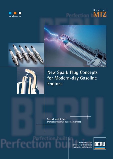
<strong>New</strong> <strong>Spark</strong> <strong>Plug</strong> <strong>Concepts</strong><br />
for Modern-day Gasoline<br />
Engines<br />
Special reprint from<br />
Motortechnischen Zeitschrift (MTZ)
DEVELOPMENT<br />
2<br />
MTZ 02I2007 Volume 68<br />
Ignition<br />
<strong>New</strong> <strong>Spark</strong> <strong>Plug</strong> <strong>Concepts</strong> for<br />
Modern-day Gasoline Engines<br />
The development of gasoline engines is following the trend of lower fuel consumption<br />
allied to lower emissions and enhanced driving enjoyment. Modified <strong>com</strong>bustion<br />
systems and small, supercharged engines are the consequence. This is resulting<br />
in new demands being placed on the ignition system, especially the spark plug. This<br />
article by BERU sets out the state of the art and looks at prospective future solutions.
1 Introduction<br />
Gasoline engine technology is on the move.<br />
For a long time developments were dominated<br />
by naturally-aspirated engines<br />
with intake manifold fuel injection and<br />
controlled three-way catalytic converters.<br />
We are currently in a phase of major change.<br />
The key driver of these developments is<br />
the demand for lower fuel consumption<br />
and emissions. Partly variability in the valve<br />
drive based on phasers or valve lift control<br />
as well as direct injection systems<br />
with wall or air guided <strong>com</strong>bustion have<br />
already been introduced into mass production<br />
[1].<br />
The latest generation of fuel injection<br />
systems featuring piezo-controlled injectors,<br />
an outward opening conical jet nozzle,<br />
multiple injection and jet-guided mixture<br />
formation is extending [2] the range of<br />
unchoked [3], lean-burn engine operation<br />
and translating reduced charge cycle losses<br />
into consumption benefits. The position of<br />
the injector between the valves is <strong>com</strong>parable<br />
to the layout in state of the art diesel<br />
engine. The spark gap is shifted into the tapered<br />
surface area of the injection jet [4],<br />
resulting in the key demands in terms of<br />
smaller designs, positioned ground electrode<br />
and more precise spark location positioning,<br />
Figure 1.<br />
There is also a trend toward downsizing<br />
with supercharging. Turbochargers with<br />
variable turbine geometry or two-stage<br />
charging are deployed in top-of-the-range<br />
engine variants. The increased charge density<br />
results in a higher ignition voltage requirement,<br />
which – especially with slimmer<br />
spark plugs – poses greater demands<br />
in terms of the dielectric and mechanical<br />
properties of the spark plug ceramic.<br />
Based on the example of the development<br />
of a new BERU M12 spark plug, the<br />
following presentation illustrates how the<br />
new demands can be met by means of mo-<br />
dified design, material selection and application.<br />
2 State of the Art<br />
The principal requirements – reliable ignition,<br />
adequacy for cold starting and repeat<br />
starting, and high mileage – can be met by a<br />
variety of spark plug concepts [5]. Combustion<br />
quality, cold starting, service life and cost<br />
factors are key to the choice of concept.<br />
2.1 Low-cost <strong>Concepts</strong><br />
Nickel alloy based electrodes are <strong>com</strong>mon<br />
solutions in this segment. Depending on<br />
the engine requirements, single or multiple<br />
electrodes, in air and/or surface gap configuration,<br />
are deployed to improve cold starting.<br />
The modest cost means <strong>com</strong>promises<br />
must be made in terms of service life.<br />
2.2 High-end <strong>Concepts</strong><br />
Different platinum or iridium based noble<br />
metal alloys on the electrodes are used in<br />
this segment. Similarly to the low-cost spark<br />
plugs, there are various electrode layouts<br />
and spark gap configurations. The higher<br />
cost is justified by outstanding durability.<br />
3 Requirements for <strong>New</strong> <strong>Spark</strong> <strong>Plug</strong> Generations<br />
The new direct fuel injection systems mean<br />
that there is less room for the spark plug in<br />
the cylinder head. This means the thread<br />
has to be made longer and/or the spark<br />
plug geometry has to be modified. M12<br />
spark plugs are in widespread use, though<br />
they provide less ceramic wall thickness<br />
than conventional M14 spark plugs.<br />
In addition, the downsizing engine concepts<br />
featuring supercharging, and the resultant<br />
increase in charge density, means<br />
Figure 1: Matching of spark plug<br />
to injection jet in gasoline direct<br />
injection engine<br />
(photo: Daimler-Chrysler)<br />
Authors<br />
Dr. Manfred Adolf<br />
is Head of Development<br />
Ignition Technology at<br />
BERU AG in Germany.<br />
Thomas Alban<br />
is responsible for<br />
Production Process<br />
Management at<br />
BERU AG in Germany.<br />
Dipl.-Ing. Hans Houben<br />
Vice President Research<br />
& Development at<br />
BERU AG in Germany.<br />
Dipl.-Ing. (FH)<br />
Martin Knoch<br />
is employee for advanced<br />
development at BERU AG<br />
in Germany.<br />
Werner Niessner<br />
is Head of <strong>Spark</strong> <strong>Plug</strong><br />
Development at BERU AG<br />
in Germany.<br />
Dipl.-Ing. (FH)<br />
Ulrich Stockmeier<br />
is employee for Ignition<br />
System Application at<br />
BERU AG in Germany.<br />
MTZ 02I2007 Volume 68 3
DEVELOPMENT<br />
Figure 2: Modifying the organic additives enables a substantially reduction of pore diameter<br />
Figure 3: Improvement of ceramic properties based on modified additives<br />
higher voltages will be required. The contradictory<br />
demands – thinner walls on the<br />
insulator and higher voltage requirement<br />
– necessitate the development of new materials,<br />
geometries and methods.<br />
3.1 Importance of the Ceramic<br />
An alumina-based ceramic with an Al 2 O 3<br />
(aluminium oxide) content of at least 94 %<br />
has established itself as the standard insulator<br />
material for passenger car spark<br />
plugs, because such a material meets the<br />
electrical and mechanical demands in<br />
terms of dielectric strength even at high<br />
temperatures (up to 1,000 °C). Moreover,<br />
high levels of raw material availability and<br />
process safety ensure an optimum cost/benefit<br />
ratio.<br />
To produce the ceramic, minerals such<br />
as kaolin, soapstone and dolomite are ad-<br />
4<br />
MTZ 02I2007 Volume 68<br />
Ignition<br />
ded to the Al 2 O 3 . They deliver the oxides<br />
(SiO 2 , CaO and MgO) required for the sintering<br />
process and also enhance the rheological<br />
properties of the spray slip and the plastic<br />
properties of the pellets required for the<br />
pressing and grinding process.<br />
Alongside the morphology of the Al 2 O 3<br />
crystallites, the oxides used determine the<br />
dielectric and mechanical properties of the<br />
insulator, especially at high temperatures.<br />
The factor considered to be key in determining<br />
the material properties of the ceramic<br />
currently employed, however, is the residual<br />
porosity, caused by pellets which have<br />
not been destroyed by pressing. Pores with<br />
diameters of as much as 50 μm result in<br />
some cases.<br />
3.2 Improvement of Ceramic Properties<br />
In order to substantially reduce the resi-<br />
dual porosity and so improve dielectric<br />
and mechanical strength, modifications<br />
to the additive materials were investigated.<br />
To this end, wax suspensions were added<br />
to the slip prior to spray drying. They<br />
influence the adhesion of the primary pellet<br />
particles and the drying process during<br />
spraying, and assist <strong>com</strong>paction during<br />
molding. The reduction in residual porosity<br />
achieved in this way is presented in Figure<br />
2. The improvements in properties<br />
achieved with this ceramic (designated<br />
V41) are presented in Figure 3. The plan is<br />
to manufacture M12 spark plugs with a<br />
voltage requirement of > 40 kV from this<br />
modified ceramic in future.<br />
The use of Al 2 O 3 also offers further potential<br />
for improvement based on a reduction<br />
of the sinter additives, the use of<br />
raw materials with smaller grain sizes,<br />
and on process modifications, enabling<br />
dielectric strengths of > 30 kV/mm to be<br />
achieved.<br />
3.3 <strong>Spark</strong> <strong>Plug</strong> Design Modifications<br />
For spark plugs with M12 threads the standard<br />
allows three different dimensions:<br />
– M12 x 1.25 with Hex 16 mm and insulator<br />
neck 10.5 mm (ISO 2705)<br />
– M12 x 1.25 with Hex 14 mm and insulator<br />
neck 9.0 mm (ISO 16 246)<br />
– M12 x 1.25 with Bi-hex 14 mm and insulator<br />
neck 10.5 mm (ISO 22 977).<br />
In these dimensions, the gas pressure tightness<br />
of the spark plug must be safely attained<br />
at the specified tightening torque.<br />
The development goal was to shape the metallic<br />
spark plug body so that the required<br />
tightness is safely attained at the maximum<br />
tightening torque of 25 Nm. Figure 4<br />
presents the gas pressure tightness of the<br />
spark plug as a function of the tightening<br />
torque. In conformance to the gas pressure<br />
tightness, the measurable deformation of<br />
the thread begins at 40 Nm, Figure 5.<br />
4 Service Life Requirement<br />
The required service life of M12 spark plugs<br />
is 60,000 to 100,000 km – the same as for<br />
the M14. The increase in voltage requirement<br />
due to wear of the spark plug spark<br />
gap needs to be minimized in order to<br />
achieve such durability, and that necessitated<br />
the development of new electrode geometries,<br />
materials and methods.<br />
4.1 Wear of Low-cost <strong>Spark</strong> <strong>Plug</strong>s<br />
The wearing mechanism on nickel alloys,<br />
Figure 6, is essentially dictated by oxidation,<br />
because the oxide layer which forms penet-
ates through to the base material due to<br />
the spark discharge and is destroyed in the<br />
process. The thicker the oxide layer, the deeper<br />
are the craters, and the greater is the<br />
material loss. As a result, nickel alloys with<br />
a thinner, permanent oxide layer are required.<br />
Figure 7 presents the influence of<br />
different alloying additives on the wear index<br />
determined during engine running.<br />
4.2 Wear Reduction on High-end<br />
<strong>Spark</strong> <strong>Plug</strong>s<br />
The wear of spark plugs featuring electrodes<br />
clad in oxidation-stabilized noble metal is fundamentally<br />
lower. A permanent join of the<br />
noble metal to the nickel-based spark plug<br />
electrodes is essential though. The key factor<br />
in attaining this is to counteract the thermomechanical<br />
stresses occurring due to differing<br />
coefficients thermal expansion in the weld<br />
zone. This is done – Figure 8 (A) based on the<br />
example of a ground electrode – by laser welding,<br />
forming an additional alloy zone in the<br />
border area of the noble metal cladding.<br />
5 Manufacture of High-end <strong>Spark</strong> <strong>Plug</strong>s<br />
A further key requirement for reliable sparking<br />
of gasoline engines featuring jet-guided<br />
direct injection is a more precisely manufactured<br />
spark plug with a positionable<br />
ground electrode. This demands defined<br />
spark gap flow control in the <strong>com</strong>bustion<br />
chamber as well as narrower injector/spark<br />
plug matching tolerances, with a tight<br />
spark location tolerance.<br />
5.1 Noble Metal <strong>Spark</strong> <strong>Plug</strong>s<br />
with High Coverage<br />
<strong>Spark</strong> plugs for high mileages are usually<br />
designed with a noble metal cladding on<br />
the center and ground electrodes. A key factor<br />
determining the service life durability<br />
of the spark plug is the coverage of the noble<br />
metals, Figure 8 (B). BERU has developed a<br />
method which ensures at least 92 % coverage<br />
of the noble metal surfaces. This permits<br />
a reduction in noble metal usage.<br />
5.2 Reduction of Manufacturing Tolerance<br />
Adding together all the tolerances, conventional<br />
spark plugs achieve an accuracy of<br />
spark gap positioning in the <strong>com</strong>bustion<br />
chamber of up to 1.7 mm. Consequently,<br />
they are not suitable to meet the needs described,<br />
as misfiring may occur [6].<br />
By optimizing the manufacturing processes<br />
and applying different thicknesses<br />
of the inner gasket, the sparking position<br />
tolerances have been narrowed to such an<br />
extent that the position of the spark gap is<br />
Figure 4: Spread of leakage quantity of an M12 spark plug as a function of tightening torque<br />
Figure 5: Spread of thread elongation of an M12 spark plug as a function of tightening torque<br />
Figure 6: Influence of the nickel alloy on the formation of the oxide layer in engine running<br />
safeguarded to an accuracy of maximum<br />
± 0.2 mm, Figure 9.<br />
5.3 Position-oriented Ground Electrode<br />
Just as important as precise spark location<br />
positioning is a defined alignment of the<br />
ground electrode, so that the mixture formation<br />
is not hindered. This precise positioning<br />
of the ground electrode likewise demands a<br />
defined thread face in the cylinder head.<br />
The shape and position of the thread<br />
profile are used as a reference for precisely<br />
positioned welding of the ground electrode.<br />
In this, the body is piloted on the outer<br />
sealing seat and with a turning movement<br />
the body‘s thread profile is set to the<br />
desired position within a measurement<br />
window. By aligning, adjusting and positioning<br />
the body using an optical measurement<br />
system, a tolerance of ± 15° is attained,<br />
Figure 9.<br />
6 Measurement System<br />
The development of an engine-specific<br />
spark plug demands close collaboration<br />
between the vehicles and spark plug ma-<br />
MTZ 02I2007 Volume 68 5
DEVELOPMENT<br />
Figure 7: Influence of the nickel alloy on relative wear in engine running<br />
Figure 8: Formation of the alloy zone in the border area of the noble metal cladding in<br />
laser welding (A); minimum 92 % coverage of the noble metal surfaces based on optimized<br />
manu facturing process (B)<br />
nufacturers. The requirements involved in<br />
achieving this include facilities for determining<br />
– the appropriate thermal value of the<br />
spark plug<br />
– the electrode temperatures<br />
– the ignition voltage requirement<br />
– the ignition voltage supply.<br />
It is also necessary to test the cold starting<br />
behavior of the spark plug. This special<br />
measuring system was developed by BERU,<br />
and is available as a mobile application unit.<br />
6.1 Thermal Value<br />
The thermal value (TV) is an indicator of<br />
6<br />
MTZ 02I2007 Volume 68<br />
Ignition<br />
the thermal withstand capability of the<br />
spark plug. It is a function of the ratio of<br />
the absorbed heat to the discharged heat. It<br />
is determined on the basis of <strong>com</strong>parative<br />
measurements against a reference. The aim<br />
of thermal measures in the design of a<br />
spark plug is to achieve the best <strong>com</strong>promise<br />
between good cold starting performance<br />
and adequate safety prior to preignition in<br />
the engine, taking into account the electrode<br />
temperatures.<br />
The facility to record the preignition<br />
and postignition behavior by means of ionic<br />
current measurement enables precise<br />
definition of the thermal value.<br />
Figure 9: M12 spark plug with positioned<br />
ground electrode and precise spark location<br />
6.2 Electrode Temperature<br />
Measuring the temperature of the center<br />
and ground electrodes safeguards service<br />
life durability, as electrode burn-off increases<br />
drastically as the temperature rises. In<br />
mobile operation, spark plugs are prefitted<br />
with thermocouples for the purpose. For<br />
stationary <strong>com</strong>parative measurement, a special<br />
engine with an optical access for pyrometric<br />
measurement is available, Figure 10.<br />
6.3 Ignition Voltage Requirement<br />
The electrode gap (EG) of the spark plugs<br />
must be selected such that safe mixture<br />
ignition (large EG) with an adequate ignition<br />
voltage reserve (small EG) is ensured<br />
even at the end of the spark plugs‘ service<br />
life. Measurement of the ignition voltage<br />
requirement and supply is used to check<br />
the ignition voltage reserve. These measurements<br />
are most usefully performed in the<br />
vehicle, with spark plugs which have reached<br />
the end of their service lives, as this is<br />
the best way to represent the dynamic driving<br />
states critical to the ignition voltage<br />
requirement.<br />
The BERU mobile measurement system<br />
permits selective measurement of the ignition<br />
voltage requirement and supply at up<br />
to eight cylinders simultaneously. The system<br />
determines the high voltage values<br />
over time, as well as the envelopes of minimum<br />
and maximum values. It also provides<br />
information on the frequency distri-
Figure 11: The new BERU cold cell with two-axle roller dynamometer<br />
butions of the individual high voltage<br />
classes.<br />
6.4 Cold Start Test<br />
The cold start characteristics of the spark<br />
plugs are checked following a defined test<br />
cycle in the vehicle on the roller dynamometer.<br />
The cycle is run at ambient temperatures<br />
and coolant temperatures down to -<br />
20 °C, and <strong>com</strong>prises multiple starts followed<br />
by driving under low engine load.<br />
Assessment criteria are the number of<br />
possible starts and/or the characteristic of<br />
the shunt – that is, the short to ground due<br />
to fuel or soot deposits on the insulator nose<br />
resulting from in<strong>com</strong>plete <strong>com</strong>bustion.<br />
Figure 10: Pyrometric temperature<br />
measurement in a<br />
special engine with optical<br />
access on a four-pole surface-gap<br />
spark plug<br />
7 Technical Test Requirements<br />
To perform the above test, a cold cell with a<br />
roller dynamometer is required, as is available<br />
at the BERU R&D center, Figure 11. Key<br />
features:<br />
Cold cell<br />
– Entry height: 3.50 meters. Length: 14<br />
meters. Width: 5.50 meters.<br />
– Temperature range: -40 °C to +30 °C<br />
Roller dynamometer<br />
– Model: Two-axle roller dynamometer<br />
with 48 inch roller diameter<br />
– Rated power output: 195 kW per axle<br />
(continuous running)<br />
– Vmax: 250 km/h<br />
– Track width: 914 mm to 2,743 mm<br />
– Wheelbase: 2,100 mm to 4,700 mm<br />
– Axle load: 3.5 tones per axle<br />
8 Summary and Outlook<br />
The effects of changing gasoline engine<br />
<strong>com</strong>bustion systems were presented based<br />
on the example of an M12 spark plug.<br />
The small design requires optimization<br />
of the ceramic insulator and the mechanical<br />
construction. Precise spark locations<br />
and positioned ground electrodes can be<br />
attained by improved processes and new<br />
manufacturing methods. High service life<br />
expectations are met by high-end noble<br />
metal concepts. Other requirements include<br />
appropriate application tools and experience,<br />
in order to achieve an optimum design<br />
of the spark plug within a short space<br />
of time.<br />
The trend outlined at the beginning will<br />
be sustained: increasing charge levels, higher<br />
specific power outputs and ever tighter<br />
space inside the cylinder head mean spark<br />
plugs will be<strong>com</strong>e even smaller. The first<br />
project – an M10 spark plug – has already<br />
been launched, posing a challenge to<br />
BERU‘s engineers.<br />
References<br />
[1] Alt, M.; Schaffner, P.; Rothenberge, P.: „Effizienzsteigerung<br />
des Ottomotors durch Technologiekombinationen“<br />
[Increasing the efficiency of the gasoline engine<br />
by means of technology <strong>com</strong>binations]. 15th Aachen<br />
Engine Colloquium, 2006<br />
[2] Warnecke, V.; Achleitner, E.; Bäcker, H.: „Entwicklungsstand<br />
des Siemens VDO Piezo-Einspritzsystems<br />
für strahlgeführte Brennverfahren“ [Development status<br />
of the Siemens VDO piezo fuel injection system for<br />
jet-guided <strong>com</strong>bustion methods]. 27th Vienna International<br />
Engine Symposium, 2006<br />
[3] Welter, A.; Unger, H.; Hoyer, U.; Brüner, T.; Kiefer, W.:<br />
„Der neue aufgeladene BMW-Reihensechszylinder-<br />
Ottomotor“ [The new supercharged BMW straight sixcylinder<br />
gasoline engine]. 15th Aachen Engine Colloquium,<br />
2006<br />
[4] Waltner, A.; Lückert, P.; Schaupp, U.; Rau, E.; Kemmler,<br />
R.; Weller, R.: „Die Zukunftstechnologie des Ottomotors<br />
- Strahlgeführte Direkteinspritzung mit Piezo-Injektor“<br />
[Future technology of the gasoline engine –<br />
Jet-guided direct fuel injection with piezo injector].<br />
27 th Vienna International Engine Symposium, 2006<br />
[5] „Alles über Zündkerzen“ [All about spark plugs]. Technical<br />
Information Bulletin no. 02, BERU AG (2004) and<br />
Meyer, J.; Niessner, W. „Neue Zündkerzentechnik für<br />
höhere Anforderungen“ [<strong>New</strong> spark plug technology<br />
for higher demands]. ATZ/MTZ special, „System Partners<br />
97“, (1997)<br />
[6] Herden, W.; Vogel, M.: „Perspektiven alternativer<br />
Zündsysteme. Diesel- und Benzindirekteinspritzung III“<br />
[Prospects for alternative ignition systems – Diesel<br />
and gasoline direct injection III], publ. Expert-Verlag<br />
(2005) and Willand, J.; Suck, G.; Schintzel, K.: „Anforderungen<br />
an die Einspritzsysteme strahlgeführter<br />
Brennverfahren“ [Requirements for fuel injection systems<br />
using jet-guided <strong>com</strong>bustion methods] (ebd.)<br />
MTZ 02I2007 Volume 68 7
Printed in Germany · 3.02.07 · Bestell- Nr. 5 000 001 092<br />
BERU Aktiengesellschaft<br />
Mörikestrasse 155,<br />
D-71636 Ludwigsburg<br />
Postfach 229,<br />
D-71602 Ludwigsburg<br />
Telefon: ++49/7141/132-693<br />
Telefax: ++49/7141/132-220<br />
info@beru.de<br />
www.beru.<strong>com</strong>


