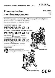
Air-Operated Diaphragm Pumps VERDER VA 15 VERDER VA 15 VERDER VA 20
verderair va 20 - Double Diaphragm Pump
verderair va 20 - Double Diaphragm Pump

Create successful ePaper yourself
Turn your PDF publications into a flip-book with our unique Google optimized e-Paper software.
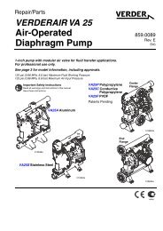
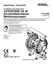
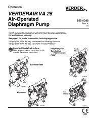
INSTRUCTIONS–PARTS LIST<br />
<strong>Air</strong>-<strong>Operated</strong><br />
<strong>Diaphragm</strong> <strong>Pumps</strong><br />
819.6900<br />
Rev. V<br />
<br />
For fluid transfer applications. For professional use only.<br />
100 psi; 0.7 MPa; 7 bar Maximum Fluid Working Pressure<br />
100 psi; 0.7 MPa; 7 bar Maximum <strong>Air</strong> Input Pressure<br />
POLYPROPYLENE, AND PVDF<br />
<strong>VERDER</strong> <strong>VA</strong> <strong>15</strong><br />
ACETAL* AND CONDUCTIVE POLYPROPYLENE*<br />
<strong>VERDER</strong> <strong>VA</strong> <strong>15</strong><br />
*These pumps are<br />
certified.<br />
ALUMINUM AND STAINLESS STEEL*<br />
<strong>VERDER</strong> <strong>VA</strong> <strong>20</strong><br />
*These pumps are<br />
certified.<br />
Refer to the Pump Listing on page <strong>20</strong> to determine the Model<br />
No. of your pump.<br />
Patents Pending<br />
Important Safety Instructions<br />
Read all warnings and instructions in this manual.<br />
Save these instructions.<br />
9065A<br />
<strong>VERDER</strong> <strong>VA</strong> <strong>15</strong><br />
9246A<br />
<strong>VERDER</strong> <strong>VA</strong> <strong>20</strong>
Table of Contents<br />
Safety Warnings . . . . . . . . . . . . . . . . . . . . . . . . . . . . . . . . . . . . . 2<br />
Installation . . . . . . . . . . . . . . . . . . . . . . . . . . . . . . . . . . . . . . . . . . 4<br />
Operation . . . . . . . . . . . . . . . . . . . . . . . . . . . . . . . . . . . . . . . . . 10<br />
Maintenance . . . . . . . . . . . . . . . . . . . . . . . . . . . . . . . . . . . . . . . 11<br />
Troubleshooting . . . . . . . . . . . . . . . . . . . . . . . . . . . . . . . . . . . . 12<br />
Service . . . . . . . . . . . . . . . . . . . . . . . . . . . . . . . . . . . . . . . . . . . 13<br />
<strong>VERDER</strong>AIR <strong>VA</strong> <strong>15</strong> and <strong>VERDER</strong>AIR <strong>VA</strong> <strong>20</strong><br />
Pump Listing . . . . . . . . . . . . . . . . . . . . . . . . . . . . . . . . . . . . . . . <strong>20</strong><br />
<strong>VERDER</strong>AIR <strong>VA</strong> <strong>15</strong> and <strong>VERDER</strong>AIR <strong>VA</strong> <strong>20</strong><br />
Repair Kits . . . . . . . . . . . . . . . . . . . . . . . . . . . . . . . . . . . . . . . . 23<br />
Parts<br />
<strong>VERDER</strong>AIR <strong>VA</strong> <strong>15</strong> and <strong>VERDER</strong>AIR <strong>VA</strong> <strong>20</strong><br />
Common Parts . . . . . . . . . . . . . . . . . . . . . . . . . . . . . . . . . . . 24<br />
<strong>VERDER</strong>AIR <strong>VA</strong> <strong>15</strong> Parts Drawing . . . . . . . . . . . . . . . . . 25<br />
<strong>VERDER</strong>AIR <strong>VA</strong> <strong>15</strong> Fluid Section Parts List . . . . . . . . . . 26<br />
<strong>VERDER</strong>AIR <strong>VA</strong> <strong>20</strong> Parts Drawing . . . . . . . . . . . . . . . . . 28<br />
<strong>VERDER</strong>AIR <strong>VA</strong> <strong>20</strong> Fluid Section Parts List . . . . . . . . . . 29<br />
Torque Sequence . . . . . . . . . . . . . . . . . . . . . . . . . . . . . . . . . . . 30<br />
<strong>VERDER</strong> <strong>VA</strong> <strong>15</strong>:<br />
Technical Data . . . . . . . . . . . . . . . . . . . . . . . . . . . . . . . . . . . 31<br />
Dimensions . . . . . . . . . . . . . . . . . . . . . . . . . . . . . . . . . . . . . 32<br />
<strong>VERDER</strong> <strong>VA</strong> <strong>20</strong>:<br />
Technical Data . . . . . . . . . . . . . . . . . . . . . . . . . . . . . . . . . . . 33<br />
Dimensions . . . . . . . . . . . . . . . . . . . . . . . . . . . . . . . . . . . . . 34<br />
<strong>VERDER</strong>AIR <strong>VA</strong> <strong>15</strong> and <strong>VERDER</strong>AIR <strong>VA</strong> <strong>20</strong><br />
Performance Charts . . . . . . . . . . . . . . . . . . . . . . . . . . . . . . . . 35<br />
Customer Services/Guarantee . . . . . . . . . . . . . . . . . . . . . . . . 37<br />
INSTRUCTIONS<br />
EQUIPMENT MISUSE HAZARD<br />
Symbols<br />
Warning Symbol<br />
Warning<br />
This symbol alerts you to the possibility of serious injury or<br />
death if you do not follow the instructions.<br />
Caution Symbol<br />
Caution<br />
This symbol alerts you to the possibility of damage to or destruction<br />
of equipment if you do not follow the instructions.<br />
Warning<br />
Equipment misuse can cause the equipment to rupture or malfunction and result in serious injury.<br />
This equipment is for professional use only.<br />
<br />
Read all instruction manuals, tags, and labels before operating the equipment.<br />
<br />
<br />
<br />
<br />
<br />
<br />
<br />
<br />
<br />
<br />
Use the equipment only for its intended purpose. If you are not sure, call your <strong>VERDER</strong> distributor.<br />
Do not alter or modify this equipment. Use only genuine <strong>VERDER</strong> parts and accessories.<br />
Check equipment daily. Repair or replace worn or damaged parts immediately.<br />
Do not exceed the maximum working pressure of the lowest rated component in your system. This equipment<br />
has a 100 psi; 0.7 MPa (7 bar) maximum working pressure at 100 psi; 0.7 MPa (7 bar) maximum incoming<br />
air pressure.<br />
Use fluids and solvents that are compatible with the equipment wetted parts. Refer to the Technical Data<br />
section of all equipment manuals. Read the fluid and solvent manufacturer’s warnings.<br />
Route hoses away from traffic areas, sharp edges, moving parts, and hot surfaces. Do not expose <strong>VERDER</strong><br />
hoses to temperatures above 180F (82C) or below –40C (–40C).<br />
Wear hearing protection when operating this equipment.<br />
Do not lift pressurized equipment.<br />
Comply with all applicable local, state, and national fire, electrical, and safety regulations.<br />
Do not use 1.1.1-trichloroethane, methylene chloride, other halogenated hydrocarbon solvents or fluids<br />
containing such solvents in pressurized aluminum equipment. Such use could result in a chemical reaction,<br />
with the possibility of explosion.<br />
2 819.6900
TOXIC FLUID HAZARD<br />
Warning<br />
Hazardous fluid or toxic fumes can cause serious injury or death if splashed in the eyes or on the skin, inhaled, or<br />
swallowed.<br />
<br />
<br />
<br />
<br />
<br />
<br />
Know the specific hazards of the fluid you are using.<br />
Do not lift a pump under pressure. If dropped, the fluid section may rupture. Always follow the Pressure Relief<br />
Procedure on page 10 before lifting the pump.<br />
Store hazardous fluid in an approved container. Dispose of hazardous fluid according to all local, state, and<br />
national guidelines.<br />
Always wear protective eyewear, gloves, clothing, and respirator as recommended by the fluid and solvent<br />
manufacturer.<br />
Pipe and dispose of the exhaust air safely, away from people, animals, and food handling areas. If the<br />
diaphragm fails, the fluid is exhausted along with the air. Read <strong>Air</strong> Exhaust Ventilation on page 6.<br />
Never use an acetal pump to pump acids. Take precautions to avoid acid or acid fumes from contacting the<br />
pump housing exterior. Stainless steel parts will be damaged by exposure to acid spills and fumes.<br />
FIRE AND EXPLOSION HAZARD<br />
Improper grounding, poor ventilation, open flames, or sparks can cause a hazardous condition and result in a fire<br />
or explosion and serious injury.<br />
Ground the equipment. Refer to Grounding on page 8.<br />
<br />
<br />
<br />
<br />
<br />
<br />
<br />
<br />
<br />
<br />
Never use a non–conductive polypropylene or PVDF pump with non-conductive flammable fluids as specified<br />
by your local fire protection code. Refer to Grounding on page 8 for additional information. Consult your fluid<br />
supplier to determine the conductivity or resistivity of your fluid.<br />
If there is any static sparking or you feel an electric shock while using this equipment, stop pumping<br />
immediately. Do not use the equipment until you identify and correct the problem.<br />
Provide fresh air ventilation to avoid the buildup of flammable fumes from solvents or the fluid being pumped.<br />
Pipe and dispose of the exhaust air safely, away from all sources of ignition. If the diaphragm fails, the fluid is<br />
exhausted along with the air. Read <strong>Air</strong> Exhaust Ventilation on page 6.<br />
Keep the work area free of debris, including solvent, rags, and gasoline.<br />
Electrically disconnect all equipment in the work area.<br />
Extinguish all open flames or pilot lights in the work area.<br />
Do not smoke in the work area.<br />
Do not turn on or off any light switch in the work area while operating or if fumes are present.<br />
Do not operate a gasoline engine in the work area.<br />
819.6900 3
Installation<br />
General Information<br />
<br />
<br />
<br />
The Typical Installations in Fig. 2 are only guides for<br />
selecting and installing system components. Contact your<br />
<strong>VERDER</strong> distributor for assistance in planning a system<br />
to suit your needs.<br />
Always use Genuine <strong>VERDER</strong> Parts and Accessories.<br />
Use a compatible, liquid thread sealant on all male<br />
threads. Tighten all connections firmly to avoid air or fluid<br />
leaks.<br />
Tightening Threaded Fasteners Before First<br />
Use<br />
Before using the pump for the first time, check and retorque<br />
all external fasteners. See Torque Sequence, page 30. After<br />
the first day of operation, retorque the fasteners. Although<br />
pump use varies, a general guideline is to retorque fasteners<br />
every two months.<br />
Toxic Fluid Hazard<br />
Read Toxic Fluid Hazard on<br />
page 3.<br />
Use fluids and solvents that are compatible with the equipment<br />
wetted parts. Refer to the Technical Data section of<br />
all equipment manuals. Read the fluid and solvent<br />
manufacturer’s warnings.<br />
Caution<br />
Safe Operating Temperatures<br />
Minimum (all pumps): 40 F (4 C)<br />
Maximum<br />
Acetal: 180F (82 C)<br />
Polypropylene: <strong>15</strong>0F (66 C)<br />
Aluminum, stainless steel, PVDF: 225F (107 C)<br />
These temperatures are based upon mechanical stress only<br />
and may be significantly altered by pumping certain chemicals.<br />
Consult engineering guides for chemical compatibilities<br />
and temperature limits, or contact your <strong>VERDER</strong> distributor.<br />
Mountings<br />
<br />
<br />
These pumps can be used in a variety of installations.<br />
Be sure the mounting surface can support the weight of<br />
the pump, hoses, and accessories, as well as the stress<br />
caused during operation.<br />
Fig. 2 shows some installation examples. On all installations,<br />
mount the pump using screws and nuts.<br />
Pumping High-Density Fluids<br />
High density fluids may prevent the lighter non-metallic check<br />
valve balls from seating properly, which reduces pump performance<br />
significantly. Stainless steel balls should be used for<br />
such applications.<br />
4 819.6900
Installation<br />
<strong>Air</strong> Line<br />
Warning<br />
A bleed-type master air valve (B) is required in your system<br />
to relieve air trapped between this valve and the pump.<br />
See Fig. 2. Trapped air can cause the pump to cycle unexpectedly,<br />
which could result in serious injury, including<br />
splashing in the eyes or on the skin, injury from moving<br />
parts, or contamination from hazardous fluids.<br />
Caution<br />
The pump exhaust air may contain contaminants. Ventilate<br />
to a remote area if the contaminants could affect your fluid<br />
supply. Read <strong>Air</strong> Exhaust Ventilation on page 6.<br />
1. Install the air line accessories as shown in Fig. 2. Mount<br />
these accessories on the wall or on a bracket. Be sure<br />
the air line supplying the accessories is electrically conductive.<br />
a. The fluid pressure can be controlled in either of two<br />
ways. To control it on the air side, install an air regulator<br />
(G). To control it on the fluid side, install a fluid<br />
regulator (J) near the pump fluid outlet (see Fig. 2).<br />
b. Locate one bleed-type master air valve (B) close<br />
to the pump and use it to relieve trapped air. Read<br />
the Warning above. Locate the other master air<br />
valve (E) upstream from all air line accessories and<br />
use it to isolate them during cleaning and repair.<br />
c. The air line filter (F) removes harmful dirt and<br />
moisture from the compressed air supply.<br />
2. Install an electrically conductive, flexible air hose (C)<br />
between the accessories and the 1/4 npt(f) pump air<br />
inlet. Use a minimum 1/4 in. ID air hose. Screw an air<br />
line quick disconnect coupler (D) onto the end of the air<br />
hose (C), and screw the mating fitting into the pump air<br />
inlet snugly. Do not connect the coupler (D) to the fitting<br />
yet.<br />
Installation of Remote Pilot <strong>Air</strong>lines<br />
1. Connect the air line to the pump as noted above.<br />
2. Connect 1/4 OD tubing to the push type connectors (16)<br />
on the underside of the pump.<br />
NOTE: By replacing the push type connectors, other sizes<br />
or types of fittings may be used. The new fittings will<br />
require 1/8 in. npt threads.<br />
3. Connect the other end of the tubes to the external air<br />
signal, such as <strong>VERDER</strong>’s Cycleflo (PN 819.9742) or<br />
Cycleflo II (819.9743) controllers.<br />
NOTE: The air pressure at the connectors must be at least<br />
30% of the air pressure to the air motor for the pump<br />
to operate.<br />
Fluid Suction Line<br />
If using a conductive (acetal or polypropylene) pump, use<br />
conductive hoses. If using a non-conductive pump,<br />
ground the fluid system. Read Grounding on page 8.<br />
The fluid inlet port is 1/2 in. or 3/4 in..<br />
<br />
At inlet fluid pressures greater than <strong>15</strong> psi; 0.1 MPa<br />
(1 bar), diaphragm life will be shortened.<br />
Fluid Outlet Line<br />
Warning<br />
A fluid drain valve (H) is required in your system to relieve<br />
pressure in the hose if it is plugged. See Fig. 2. The drain<br />
valve reduces the risk of serious injury, including splashing<br />
in the eyes or on the skin, or contamination from hazardous<br />
fluids when relieving pressure. Install the valve close to<br />
the pump fluid outlet.<br />
1. Use electrically conductive fluid hoses (K). The pump<br />
fluid outlet is 1/2 in. or 3/4 in. Screw the fluid fitting into<br />
the pump outlet snugly. Do not over–tighten.<br />
2. Install a fluid regulator (J) at the pump fluid outlet to control<br />
fluid pressure, if desired (see Fig. 2). See <strong>Air</strong> Line,<br />
step 1a., for another method of controlling pressure.<br />
3. Install a fluid drain valve (H) near the fluid outlet. Read<br />
the warning above.<br />
819.6900 5
Installation<br />
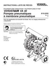
Fluid Pressure Relief Valve<br />
Caution<br />
Some systems may require installation of a pressure relief<br />
valve at the pump outlet to prevent over–pressurization and<br />
rupture of the pump or hose. See Fig. 1.<br />
Thermal expansion of fluid in the outlet line can cause over–<br />
pressurization. This can occur when using long fluid lines<br />
exposed to sunlight or ambient heat, or when pumping from a<br />
cool to a warm area (for example, from an underground tank).<br />
Over–pressurization can also occur if the <strong>VERDER</strong>AIR pump<br />
is being used to feed fluid to a piston pump, and the intake<br />
valve of the piston pump does not close, causing fluid to back<br />
up in the outlet line.<br />
1<br />
Install valve between fluid inlet and outlet ports.<br />
<strong>Air</strong> Exhaust Ventilation<br />
Read Toxic Fluid Hazard on<br />
page 3.<br />
Read Fire and Explosion<br />
Hazard on page 3.<br />
Be sure the system is properly ventilated for your type of<br />
installation. You must vent the exhaust to a safe place,<br />
away from people, animals, food handling areas, and all<br />
sources of ignition when pumping flammable or hazardous<br />
fluids.<br />
<strong>Diaphragm</strong> failure will cause the fluid being pumped to<br />
exhaust with the air. Place an appropriate container at the<br />
end of the air exhaust line to catch the fluid. See Fig. 2.<br />
2 Connect fluid inlet line here.<br />
3<br />
Connect fluid outlet line here.<br />
3<br />
The air exhaust port is 3/8 npt(f). Do not restrict the air exhaust<br />
port. Excessive exhaust restriction can cause erratic<br />
pump operation.<br />
See Venting Exhaust <strong>Air</strong> in Fig. 2. Exhaust to a remote<br />
location as follows:<br />
1<br />
1. Remove the muffler (W) from the pump air exhaust port.<br />
2<br />
2. Install an electrically conductive air exhaust hose (X)<br />
and connect the muffler to the other end of the hose.<br />
The minimum size for the air exhaust hose is 3/8<br />
in.(10 mm) ID. If a hose longer than <strong>15</strong> ft (4.57 m) is<br />
required, use a larger diameter hose. Avoid sharp bends<br />
or kinks in the hose.<br />
Fig. 1<br />
9073A<br />
3. Place a container (Z) at the end of the air exhaust line to<br />
catch fluid in case a diaphragm ruptures. See Fig. 2.<br />
6 819.6900
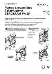
Installation<br />
ABOVE-GROUND TRANSFER INSTALLATION<br />
J<br />
C<br />
A<br />
D<br />
H<br />
E<br />
B<br />
F G<br />
Y<br />
N<br />
K<br />
KEY<br />
A<br />
B<br />
C<br />
D<br />
E<br />
F<br />
G<br />
H<br />
J<br />
K<br />
L<br />
M<br />
N<br />
Y<br />
Pump<br />
Bleed-type master air valve (required for pump)<br />
Electrically conductive air supply line<br />
<strong>Air</strong> line quick disconnect<br />
Master air valve (for accessories)<br />
<strong>Air</strong> line filter<br />
Pump air regulator<br />
Fluid drain valve (required)<br />
Fluid regulator (optional)<br />
Electrically conductive fluid supply hose<br />
Fluid suction line<br />
Underground storage tank<br />
Wall mounting bracket<br />
Ground wire (required; see page 8 for installation<br />
instructions)<br />
L<br />
M<br />
9074A<br />
<strong>20</strong>8-LITER BUNG PUMP INSTALLATION<br />
K<br />
AIR SPRAY INSTALLATION<br />
S<br />
E<br />
R<br />
F<br />
C<br />
Y<br />
D A<br />
G<br />
H<br />
V<br />
U<br />
KEY<br />
A<br />
C<br />
D<br />
H<br />
K<br />
L<br />
Y<br />
Pump<br />
Electrically conductive air supply line<br />
<strong>Air</strong> line quick disconnect<br />
Fluid drain valve (required)<br />
Electrically conductive fluid supply hose<br />
Fluid suction line<br />
Ground wire (required; see page 8 for<br />
installation instructions)<br />
P<br />
KEY<br />
A Pump<br />
C Electrically conductive air line to pump<br />
T E Gun air line shutoff valve<br />
K F <strong>Air</strong> line filter<br />
G Gun air regulator<br />
H Fluid drain valve (required)<br />
K Electrically conductive fluid supply hose<br />
P Circulating valve<br />
R Electrically conductive air line to gun<br />
S <strong>Air</strong> spray gun<br />
T Electrically conductive fluid return line<br />
U 19-liter pail<br />
V Agitator<br />
Y Ground wire (required; see page 8 for<br />
installation instructions)<br />
C<br />
Y<br />
A<br />
D<br />
L<br />
9075A<br />
H<br />
9076A<br />
KEY<br />
W Muffler<br />
X Electrically Conductive <strong>Air</strong> Exhaust Hose<br />
Z Container for Remote <strong>Air</strong> Exhaust<br />
VENTING EXHAUST AIR<br />
Z<br />
Fig. 2<br />
All wetted and non-wetted pump parts must be<br />
compatible with the fluid being pumped.<br />
X<br />
W<br />
04054<br />
819.6900 7
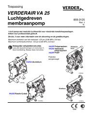
Installation<br />
Grounding<br />
Warning<br />
FIRE AND EXPLOSION HAZARD<br />
This pump must be grounded. Before operating<br />
the pump, ground the system as explained<br />
below. Also read the section Fire and Explosion<br />
Hazard on page 3.<br />
The acetal and conductive polypropylene<br />
<strong>VERDER</strong>AIR <strong>VA</strong> <strong>15</strong> pumps contain a conductive<br />
additive that makes the wetted parts conductive.<br />
Attaching the ground wire to the grounding screw<br />
(106) grounds the wetted parts. See grounding screw on<br />
page 25.<br />
The metal <strong>VERDER</strong>AIR <strong>VA</strong> <strong>20</strong> pumps have a grounding<br />
strip connecting the vee clamps (109). Attach a ground wire<br />
to the grounding strip with the screw, lockwasher, and nut as<br />
shown in the Grounding Detail on page 28.<br />
The non–conductive polypropylene and PVDF <strong>VERDER</strong>AIR<br />
<strong>VA</strong> <strong>15</strong> pumps are not conductive.<br />
When pumping conductive flammable fluids, always ground<br />
the entire fluid system by making sure the fluid system has<br />
an electrical path to a true earth ground (see Fig. 3). Never<br />
use a non–conductive polypropylene or PVDF pump with<br />
non-conductive flammable fluids as specified by your local<br />
fire protection code.<br />
US Code (NFPA 77 Static Electricity) recommends a conductivity<br />
greater than 50 x 10 –12 Siemans/meter (ohms/meter)<br />
over your operating temperature range to reduce<br />
the hazard of fire. Consult your fluid supplier to determine<br />
the conductivity or resistivity of your fluid. The resistivity<br />
must be less than 2 x 10 12 ohm-centimeters.<br />
To reduce the risk of static sparking, ground the pump and all<br />
other equipment used or located in the pumping area. Check<br />
your local electrical code for detailed grounding instructions<br />
for your area and type of equipment.<br />
Ground all of this equipment:<br />
Pump: The metal pump has a grounding strip in front of<br />
the center housing. The acetal and conductive polypropylene<br />
pumps have a grounding screw on the top manifold.<br />
Connect the non-clamp end of the ground wire to the<br />
grounding strip or grounding screw, and connect the<br />
clamp end of the ground wire to a true earth ground. To<br />
order a ground wire and clamp, order Part No. 819.0<strong>15</strong>7.<br />
<br />
<br />
<br />
<br />
KEY<br />
A<br />
H<br />
S<br />
T<br />
Y<br />
<strong>Air</strong> and fluid hoses: Use only electrically conductive<br />
hoses.<br />
<strong>Air</strong> compressor: Follow the manufacturer’s recommendations.<br />
Solvent pails used when flushing: Follow the local code.<br />
Use only grounded metal pails, which are conductive. Do<br />
not place the pail on a non-conductive surface, such as<br />
paper or cardboard, which interrupts the grounding continuity.<br />
Fluid supply container: Follow the local code.<br />
GROUNDING A PUMP<br />
Z<br />
Pump<br />
Fluid drain valve (required)<br />
Dispense valve<br />
Fluid drain line<br />
Fluid section grounding via grounding strip or grounding<br />
screw (required for metal and acetal pumps)<br />
Container ground wire (required)<br />
1 Hose must be conductive.<br />
2<br />
Dispense valve nozzle must be in contact with container.<br />
Y<br />
Z<br />
Y<br />
A<br />
H<br />
Y<br />
T<br />
1<br />
NOTE: When pumping conductive flammable fluids with a<br />
non–conductive polypropylene or PVDF pump, always<br />
ground the fluid system. See the warning<br />
above. Fig. 3 shows a recommended method of<br />
grounding flammable fluid containers during filling.<br />
Fig. 3<br />
S<br />
2<br />
9079A<br />
8 819.6900
Installation<br />
Changing the Orientation of the Fluid Inlet and<br />
Outlet Ports (<strong>VERDER</strong> <strong>VA</strong> <strong>15</strong>)<br />
1 Torque to 80 to 90 in-lb (9 to 10 Nm). See Torque<br />
Sequence, page 30.<br />
You can change the orientation of the fluid inlet and outlet<br />
ports by repositioning the manifolds. For <strong>VERDER</strong>AIR <strong>VA</strong> <strong>15</strong>,<br />
see Fig. 4. For <strong>VERDER</strong>AIR <strong>VA</strong> <strong>20</strong>, see Fig. 5.<br />
1. Remove the four manifold nuts (109) or bolts (105).<br />
109<br />
1<br />
2. Turn the manifold to the desired position, reinstall the<br />
nuts or bolts, and torque to 80 to 90 in-lb (9 to 10 Nm).<br />
See Torque Sequence, page 30.<br />
outlet<br />
NOTE: Make sure all manifold o-rings are positioned<br />
correctly before you fasten the manifold.<br />
Manifold o-rings (139) are shown in Fig. 7<br />
and Fig. 8.<br />
NOTE: <strong>Pumps</strong> with duckbill check valves are shipped with<br />
the inlet manifold on top and the outlet manifold on<br />
the bottom. See page 14 for details.<br />
1 109<br />
inlet<br />
Fig. 4<br />
9065A<br />
1 Torque to 80 to 90 in-lb (9 to 10 Nm). See Torque<br />
Sequence, page 30.<br />
outlet<br />
1 105<br />
inlet<br />
Fig. 5<br />
1 105<br />
9071A<br />
819.6900 9
Operation<br />
Pressure Relief Procedure<br />
Warning<br />
PRESSURIZED EQUIPMENT HAZARD<br />
The equipment stays pressurized until pressure is<br />
manually relieved. To reduce the risk of serious injury<br />
from pressurized fluid, accidental spray, or splashing fluid,<br />
follow this procedure whenever you:<br />
<br />
<br />
Are instructed to relieve pressure;<br />
Stop pumping;<br />
4. Check all fittings to be sure they are tight. Use a compatible<br />
liquid thread sealant on all male threads. Tighten the<br />
fluid inlet and outlet fittings snugly. Do not over–tighten<br />
the fittings into the pump.<br />
5. Place the suction tube (if used) in the fluid to be pumped.<br />
NOTE: If the inlet fluid pressure to the pump is more than<br />
25% of the outlet working pressure, the ball check<br />
valves will not close fast enough, resulting in inefficient<br />
pump operation.<br />
6. Place the end of the fluid hose (K) into an appropriate<br />
container.<br />
<br />
<br />
Check, clean or service any system equipment;<br />
Install or clean fluid nozzles.<br />
7. Close the fluid drain valve (H).<br />
8. With the pump air regulator (G) closed, open all bleedtype<br />
master air valves (B, E).<br />
1. Shut off the air to the pump.<br />
2. Open the dispensing valve, if used.<br />
3. Open the fluid drain valve to relieve all fluid pressure,<br />
and have a container ready to catch the drainage.<br />
Flush the Pump Before First Use<br />
The pump was tested with water. Prior to first use, flush the<br />
pump thoroughly with a compatible solvent. Follow the steps<br />
under Starting and Adjusting the Pump.<br />
Starting and Adjusting the Pump<br />
9. If the fluid hose has a dispensing device, hold it open<br />
while continuing with the following step. Slowly open the<br />
air regulator (G) until the pump starts to cycle. Allow the<br />
pump to cycle slowly until all air is pushed out of the lines<br />
and the pump is primed.<br />
If you are flushing, run the pump long enough to<br />
thoroughly clean the pump and hoses. Close the air<br />
regulator. Remove the suction tube from the solvent<br />
and place it in the fluid to be pumped.<br />
Operation of Remote Piloted <strong>Pumps</strong><br />
1. Follow steps 1–8 above.<br />
2. Open the air regulator (G).<br />
Warning<br />
The pump may cycle once before the external signal is<br />
applied.<br />
1.<br />
2.<br />
Read Toxic Fluid Hazard on<br />
page 3.<br />
If lifting the pump, follow the Pressure<br />
Relief Procedure above.<br />
3. The pump will operate when air pressure is alternately<br />
applied to the push type connectors (16).<br />
NOTE: Leaving air pressure applied to the air motor for extended<br />
periods when the pump is not running may<br />
shorten the diaphragm life. Using a 3–way solenoid<br />
valve to automatically relieve the pressure on the air<br />
motor when the metering cycle is complete prevents<br />
this from occurring.<br />
Pump Shutdown<br />
3.<br />
Be sure the pump is<br />
properly grounded.<br />
Read Fire and Explosion<br />
Hazard on<br />
page 3.<br />
At the end of the work shift, relieve the<br />
pressure as described in Pressure Relief<br />
Procedure at left.<br />
10 819.6900
Maintenance<br />
Lubrication<br />
The air valve is lubricated at the factory to operate without<br />
additional lubrication. If you want to provide additional lubrication,<br />
remove the hose from the pump air inlet and add two<br />
drops of machine oil to the air inlet every 500 hours of operation<br />
or every month.<br />
Caution<br />
Do not over-lubricate the pump. Oil is exhausted through the<br />
muffler, which could contaminate your fluid supply or other<br />
equipment. Excessive lubrication can also cause the pump to<br />
malfunction.<br />
Flushing and Storage<br />
Flush the pump to prevent the fluid you are pumping from<br />
drying or freezing in the pump and damaging it. Use a compatible<br />
solvent.<br />
Always flush the pump and relieve the pressure before you<br />
store it for any length of time.<br />
Tightening Threaded Connections<br />
Before each use, check all hoses for wear or damage and<br />
replace as necessary. Check to be sure all threaded connections<br />
are tight and leak-free.<br />
Check fasteners. Tighten or retorque as necessary. Although<br />
pump use varies, a general guideline is to retorque<br />
fasteners every two months. See Torque Sequence, page<br />
30.<br />
Preventive Maintenance Schedule<br />
Establish a preventive maintenance schedule, based on<br />
the pump’s service history. This is especially important for<br />
prevention of spills or leakage due to diaphragm failure.<br />
Read Pressure Relief Procedure on<br />
page 10.<br />
819.6900 11
Troubleshooting<br />
Read Pressure Relief Procedure on page 10, and relieve the pressure before you check or service the equipment.<br />
Check all possible problems and causes before disassembling the pump.<br />
PROBLEM CAUSE SOLUTION<br />
Pump will not cycle, or cycles once and<br />
stops.<br />
Pump cycles at stall or fails to hold<br />
pressure at stall.<br />
<strong>Air</strong> valve is stuck or dirty.<br />
Leaky check valves or o-rings.<br />
Worn check balls or duckbill valves or<br />
guides.<br />
Check ball wedged in guide.<br />
Worn diaphragm shaft seals.<br />
Use filtered air.<br />
Replace.<br />
Replace.<br />
Repair or replace.<br />
Replace.<br />
Pump operates erratically. Clogged suction line. Inspect; clear.<br />
Sticky or leaking check valve balls.<br />
<strong>Diaphragm</strong> ruptured.<br />
Clean or replace.<br />
Replace.<br />
<strong>Air</strong> bubbles in fluid. Suction line is loose. Tighten.<br />
<strong>Diaphragm</strong> ruptured.<br />
Loose manifolds or damaged manifold<br />
o-rings.<br />
Loose fluid side diaphragm plates.<br />
Replace.<br />
Tighten manifold bolts or nuts; replace<br />
o-rings.<br />
Tighten.<br />
Fluid in exhaust air. <strong>Diaphragm</strong> ruptured. Replace.<br />
Pump exhausts air from clamps<br />
(metal pumps).<br />
Loose fluid side diaphragm plates.<br />
Worn diaphragm shaft seals.<br />
Loose clamps.<br />
<strong>Air</strong> valve o-ring is damaged.<br />
Tighten.<br />
Replace.<br />
Tighten clamp nuts.<br />
Inspect; replace.<br />
Pump leaks fluid from check valves. Worn or damaged check valve o-rings. Inspect; replace.<br />
12 819.6900
Service<br />
<strong>Air</strong> Valve (<strong>VERDER</strong> <strong>VA</strong> <strong>15</strong> and <strong>VERDER</strong> <strong>VA</strong> <strong>20</strong> <strong>Pumps</strong>)<br />
NOTE: <strong>Air</strong> Valve Repair Kit 819.9740 is available. Parts included in the kit are marked with a dagger () in Fig. 6 and in the Parts<br />
Drawings and Lists. A tube of general purpose grease 819.0184 is supplied in the kit. Service the air valve as follows.<br />
See Fig. 6.<br />
1. Relieve the pressure. See Pressure<br />
Relief Procedure on page 10.<br />
2. Remove the cover (10) and the o-ring (4).<br />
3. Remove the carriage plungers (7), carriages (8),<br />
carriage pins (9), and valve plate (14) from the center<br />
housing (11).<br />
4. Clean all the parts, and inspect them for wear or<br />
damage.<br />
NOTE: If you are installing the new <strong>Air</strong> Valve Repair<br />
Kit 819.9740, use all the parts in the kit.<br />
5. Grease the lapped surface of the valve plate (14), and<br />
install the valve plate with the lapped surface facing up.<br />
6. Grease the bores of the center housing (11), install the<br />
u-cup packings (2) on the carriage plungers (7), and<br />
slide the carriage plungers into the carriage plunger<br />
bores. See the following important installation notes:<br />
NOTES:<br />
<br />
<br />
When you install each u-cup packing (2) on each carriage<br />
plunger (7), make sure the lips of the u-cup packing face<br />
toward the clip end (the smaller end) of the carriage<br />
plunger.<br />
When you slide the carriage plungers (7) into the bores,<br />
slide them in with the clip ends (the smaller ends) facing<br />
toward the center of the center housing (11).<br />
7. Grease the carriage pins (9), and slide the carriage pins<br />
into the carriage pin bores.<br />
8. Install the carriages (8). Make sure the carriages engage<br />
the clip ends of the carriage plungers (7) and carriage<br />
pins (9).<br />
9. Grease the o-ring (4), and seat it in the groove around<br />
the cover opening of the center housing (11).<br />
10. Screw cover (10) into center housing, and torque cover<br />
from 80 to 100 in–lb (9.0 to 13.6 Nm).<br />
NOTE: Center housing (11) is shown separated from the<br />
air covers, but it is not necessary to remove the air<br />
covers for this service. Leave the center housing<br />
and air covers assembled for this service.<br />
5<br />
4<br />
2<br />
4 6<br />
8<br />
7<br />
5<br />
4<br />
4 6<br />
2<br />
7<br />
3<br />
14<br />
1<br />
10<br />
Included in <strong>Air</strong> Valve Repair Kit 819.9740.<br />
4 2<br />
1<br />
2<br />
3<br />
4<br />
Torque to 80 to 100 in-lb (9.0 to 13.6 Nm).<br />
Apply grease.<br />
Apply grease to lapped face.<br />
Apply grease to bores of center housing (11) before installing.<br />
11<br />
5<br />
6<br />
Fig. 6<br />
Seal lips face clip end (the smaller end) of carriage plunger (7).<br />
Install with the clip ends (the smaller ends) facing toward center of<br />
center housing (11).<br />
9<br />
2<br />
8<br />
9<br />
2<br />
9069A<br />
819.6900 13
Service<br />
Ball or Duckbill Check Valves<br />
NOTE: Fluid Section Repair Kit is available. See page 23<br />
to order the correct kit for your pump. Parts included<br />
in the kit are marked with a double dagger () in<br />
Fig. 7 and Fig. 8 and in the Parts Drawings and Lists.<br />
General purpose grease 819.0184 and Adhesive<br />
819.9741 are supplied in the kit.<br />
1. Relieve the pressure. See Pressure<br />
Relief Procedure on page 10.<br />
Inlet and Outlet for <strong>Pumps</strong> with Duckbill<br />
Check Valves<br />
<strong>Pumps</strong> with duckbill check valves are shipped with the inlet<br />
manifold on top and the outlet manifold on the bottom. To<br />
make the inlet manifold on the bottom and the outlet manifold<br />
on the top, rotate each of the four duckbill assemblies vertically<br />
180 as shown below.<br />
2. Remove the top and bottom manifolds (102, 103).<br />
3. Remove all parts shown with a dagger () in Fig. 7 and<br />
Fig. 8.<br />
139<br />
4. Clean all parts, and replace worn or damaged parts.<br />
5. Reassemble the pump.<br />
NOTE: Torque the manifold nuts (109) or bolts (105) to<br />
80 to 90 in-lb (9 to 10 Nm). See Torque Sequence,<br />
page 30.<br />
<strong>20</strong>1<br />
<strong>20</strong>2<br />
9080A<br />
14 819.6900
Service<br />
<strong>VERDER</strong> <strong>VA</strong> <strong>15</strong><br />
<strong>VERDER</strong> <strong>VA</strong> <strong>20</strong><br />
1<br />
109<br />
1<br />
105<br />
103<br />
139<br />
107<br />
<strong>20</strong>2<br />
301<br />
<strong>20</strong>2<br />
<strong>20</strong>1<br />
139<br />
102<br />
139<br />
<strong>20</strong>1<br />
139<br />
<strong>20</strong>2<br />
301<br />
<strong>20</strong>1<br />
<strong>20</strong>2<br />
<strong>20</strong>1<br />
139<br />
139<br />
106<br />
<strong>20</strong>2<br />
<strong>20</strong>1<br />
139<br />
139<br />
<strong>20</strong>2<br />
301<br />
<strong>20</strong>1<br />
139<br />
102<br />
106<br />
101<br />
139<br />
<strong>20</strong>2<br />
301<br />
<strong>20</strong>2<br />
<strong>20</strong>1<br />
139<br />
109<br />
1<br />
<strong>20</strong>1<br />
139<br />
1 Torque to 80 to 90 in-lb (9 to 10 Nm).<br />
See Torque Sequence, page 30.<br />
102<br />
Fig. 7<br />
9067A<br />
1<br />
105<br />
Fig. 8<br />
1 Torque to 80 to 90 in-lb (9 to 10 Nm).<br />
See Torque Sequence, page 30.<br />
9081A<br />
819.6900 <strong>15</strong>
Service<br />
<strong>Diaphragm</strong>s (<strong>VERDER</strong> <strong>VA</strong> <strong>15</strong>)<br />
NOTE: Fluid Section Repair Kit is available. See page 23 to order the correct kit for your pump. Parts included in the kit are<br />
marked with a double dagger () in Fig. 9 and in the Parts Drawings and Lists. General purpose grease 819.0184 and<br />
Adhesive 819.9741 are supplied in the kit. Service the diaphragms as follows. See Fig. 9.<br />
Disassembly<br />
1. Relieve the pressure. See Pressure<br />
Relief Procedure on page 10.<br />
2. Remove manifolds (102 and 103) and fluid covers (101).<br />
NOTE: Make sure all the check valve parts stay in<br />
place. See Fig. 7 on page <strong>15</strong>.<br />
3. Remove one of the fluid-side diaphragm plates (105)<br />
(whichever one comes loose first when you use a<br />
wrench on the hex of each), and pull the diaphragm<br />
shaft out of the center housing (11).<br />
4. Use a wrench on the flats of the diaphragm shaft (<strong>15</strong>) to<br />
remove the other fluid-side diaphragm plate (105) from<br />
the diaphragm shaft.<br />
5. Remove the screws (106), remove the left (114) and<br />
right (113) air covers, and remove all old gasket (12)<br />
material from the ends of the center housing (11) and the<br />
surfaces of the air covers.<br />
6. Remove the diaphragm shaft u-cups (16) and pilot pin<br />
o-rings (1).<br />
7. Inspect all parts for wear or damage, and replace as<br />
necessary.<br />
Reassembly<br />
1. Insert a diaphragm shaft u-cup (16) and a pilot pin<br />
o-ring (1) into the bores of the center housing (11).<br />
NOTE: Make sure the lips of the u-cup face out of the<br />
center housing.<br />
2. Line up the holes in the gasket (12) with the holes in the<br />
end of the center housing (11), and use six screws (106)<br />
to fasten an air cover (113 or 114) to the end of the center<br />
housing (11). Torque the screws to 35 to 45 in-lb<br />
(4.0 to 5.1 Nm).<br />
3. Position the exhaust cover (13) and o-ring (4) on the<br />
center housing (11).<br />
4. Repeat steps 1 and 2 for the other end of the center<br />
housing and the remaining air cover.<br />
5. Apply medium-strength (blue) Loctite or equivalent to the<br />
threads of the fluid-side diaphragm plates (105). Install<br />
on one end of the diaphragm shaft (<strong>15</strong>) the following<br />
parts (see proper order in Fig. 9): air-side diaphragm<br />
plate (6) diaphragm (401), and fluid-side diaphragm<br />
plate (105).<br />
NOTE: The words “AIR SIDE” on the diaphragm (401)<br />
and the flat side of the air-side diaphragm<br />
plate (6) must face toward the diaphragm<br />
shaft (<strong>15</strong>).<br />
6. Put grease on the diaphragm shaft (<strong>15</strong>), and carefully<br />
(do not damage the shaft u-cups) run the diaphragm<br />
shaft (<strong>15</strong>) through the center housing (11) bore.<br />
7. Repeat step 5 for the other end of the diaphragm<br />
shaft (<strong>15</strong>), and torque the fluid-side diaphragm<br />
plates (105) to 80 to 90 in-lb (9 to 10 Nm) at 100 rpm<br />
maximum.<br />
8. Install the muffler (3).<br />
9. Make sure all the check valve parts are in place. See<br />
Fig. 7 on page <strong>15</strong>.<br />
10. Reinstall the fluid covers (101) and manifolds (102 and<br />
103), and torque the fluid cover and manifold nuts (109)<br />
to 80 to 90 in-lb (9 to 10 Nm). See Torque Sequence,<br />
page 30.<br />
16 819.6900
Service<br />
<strong>Diaphragm</strong>s (<strong>VERDER</strong> <strong>VA</strong> <strong>15</strong>)<br />
11<br />
1<br />
4<br />
114<br />
12<br />
13<br />
7<br />
109<br />
103<br />
3<br />
5<br />
6<br />
2<br />
106<br />
16<br />
1<br />
<strong>15</strong><br />
3<br />
105 6 401<br />
4<br />
101<br />
102<br />
Included in Fluid Section Repair Kit.<br />
7<br />
109<br />
1<br />
Install with lips facing out of center housing (11).<br />
2 Torque to 35 to 45 in-lb (4.0 to 5.1 Nm).<br />
3<br />
Apply grease.<br />
4<br />
The words “AIR SIDE” on diaphragm must face toward<br />
diaphragm shaft (<strong>15</strong>).<br />
109<br />
7<br />
5<br />
Flat side of air-side diaphragm plate must face toward<br />
diaphragm shaft (<strong>15</strong>).<br />
6<br />
7<br />
Apply medium-strength (blue) Loctite or equivalent to<br />
threads, and torque to 80 to 90 in-lb (9 to 10 Nm) at 100 rpm<br />
maximum.<br />
Torque to 80 to 90 in-lb (9 to 10 Nm). See Torque Sequence,<br />
page 30.<br />
Fig. 9<br />
9066A<br />
819.6900 17
Service<br />
<strong>Diaphragm</strong>s (<strong>VERDER</strong> <strong>VA</strong> <strong>20</strong>)<br />
NOTE: Fluid Section Repair Kit is available. See page 23 to order the correct kit for your pump. Parts included in the kit are<br />
marked with a double dagger () in Fig. 10 and in the Parts Drawings and Lists. General purpose grease 819.0184 and<br />
Adhesive 819.9741 are supplied in the kit. Service the diaphragms as follows. See Fig. 10.<br />
Disassembly<br />
1. Relieve the pressure. See Pressure<br />
Relief Procedure on page 10.<br />
2. Remove the manifolds (102) and fluid covers (101).<br />
NOTE: Make sure all the check valve parts stay in<br />
place. See Fig. 8 on page <strong>15</strong>.<br />
3. Remove the grounding strip from the vee clamps (109),<br />
and remove the vee clamps.<br />
4. Remove one of the fluid-side diaphragm plates (133)<br />
(whichever one comes loose first when you use a<br />
wrench on the hex of each), and pull the diaphragm<br />
shaft out of the center housing (11).<br />
5. Use a wrench on the flats of the diaphragm shaft (<strong>15</strong>) to<br />
remove the other fluid-side diaphragm plate (133) from<br />
the diaphragm shaft.<br />
6. Remove the screws (141) and air covers (136), and<br />
remove all old gasket (12) material from the ends of the<br />
center housing (11) and the surfaces of the air covers.<br />
7. Remove the diaphragm shaft u-cups (16) and pilot pin<br />
o-rings (1).<br />
8. Inspect all parts for wear or damage, and replace as<br />
necessary.<br />
Reassembly<br />
1. Insert a diaphragm shaft u-cup (16) and a pilot pin<br />
o-ring (1) into the end of the diaphragm shaft bore of<br />
the center housing (11).<br />
NOTE: Make sure the lips of the u-cup face out of the<br />
center housing.<br />
2. Line up the holes in the gasket (12) with the holes in the<br />
end of the center housing (11), and use six screws (141)<br />
to fasten an air cover (136) to the end of the center<br />
housing (11). Torque the screws to 35 to 45 in-lb (4.0 to<br />
5.1 Nm).<br />
3. Position the exhaust cover (13) and o-ring (4) on the<br />
center housing (11).<br />
4. Repeat steps 1 and 2 for the other end of the center<br />
housing and the remaining air cover.<br />
5. Apply medium-strength (blue) Loctite or equivalent to<br />
the threads of the screws (140). Install on one end of<br />
the diaphragm shaft (<strong>15</strong>) the following parts (see<br />
proper order in Fig. 10): air-side diaphragm plate (6),<br />
diaphragm (401), fluid-side diaphragm plate (133),<br />
o-ring (1<strong>15</strong>), and screw (140).<br />
NOTE: The words “AIR SIDE” on the diaphragm (401)<br />
and the flat side of the air-side diaphragm<br />
plate (6) must face toward the diaphragm<br />
shaft (<strong>15</strong>).<br />
6. Put grease on the diaphragm shaft (<strong>15</strong>), and carefully<br />
(do not damage the shaft u-cups) run the diaphragm<br />
shaft (<strong>15</strong>) through the center housing (11) bore.<br />
7. Repeat step 5 for the other end of the diaphragm<br />
shaft (<strong>15</strong>), and torque the diaphragm shaft screws (140)<br />
to 80 to 90 in-lb (9 to 10 Nm) at 100 rpm maximum.<br />
8. Install the muffler (3).<br />
When you install the vee clamps in step 9, orient the center<br />
housing (11) so the air inlet is approximately 45 above horizontal<br />
and the muffler (3) is approximately horizontal.<br />
9. Apply thin film of grease to inside of vee clamps (109).<br />
10. Position the fluid covers (101), install the vee<br />
clamps (109) around the fluid and air covers, install the<br />
grounding strip on the vee clamps, and torque the vee<br />
clamp nuts to 80 to 90 in–lb (9 to 10 Nm). See Torque<br />
Sequence, page 30.<br />
11. Make sure all the check valve parts are in place. See<br />
Fig. 8 on page <strong>15</strong>.<br />
12. Install the manifolds (102), and torque the manifold<br />
bolts (105) to 80 to 90 in-lb (9 to 10 Nm). See Torque<br />
Sequence, page 30.<br />
18 819.6900
Service<br />
<strong>Diaphragm</strong>s (<strong>VERDER</strong> <strong>VA</strong> <strong>20</strong>)<br />
105<br />
11<br />
16 1<br />
7<br />
102<br />
2<br />
141<br />
4<br />
13<br />
3<br />
12<br />
136<br />
3<br />
101<br />
109<br />
4<br />
402 5 6<br />
4<br />
401<br />
<strong>15</strong><br />
3<br />
102<br />
1<strong>15</strong><br />
133<br />
16 1<br />
6<br />
140<br />
105<br />
7<br />
Included in Fluid Section Repair Kit.<br />
1<br />
Install with lips facing out of center housing (11).<br />
2 Torque to 35 to 45 in-lb (4.0 to 5.1 Nm).<br />
3<br />
4<br />
5<br />
6<br />
7<br />
Apply grease.<br />
The words “AIR SIDE” on diaphragm and backup diaphragm must face toward<br />
diaphragm shaft (<strong>15</strong>).<br />
Flat side of the air-side diaphragm plate must face toward diaphragm shaft (<strong>15</strong>).<br />
Apply medium-strength (blue) Loctite or equivalent to threads, and torque to<br />
80 to 90 in-lb (9 to 10 Nm) at 100 rpm maximum.<br />
Torque to 80 to 90 in-lb (9 to 10 Nm). See Torque<br />
Sequence, page 30.<br />
Fig. 10<br />
9072A<br />
819.6900 19
<strong>VERDER</strong> <strong>VA</strong> <strong>15</strong> Pump Listing<br />
Your Model No. is marked on the pump’s serial plate. See the listing of existing <strong>VERDER</strong>AIR <strong>VA</strong> <strong>15</strong> pumps below:<br />
<strong>VA</strong> <strong>15</strong> Standard <strong>Air</strong> Valve<br />
Seats<br />
Ref. No.<br />
Fluid<br />
Section<br />
and<br />
Guides Checks <strong>Diaphragm</strong>s<br />
810.6771 AC AC TF TF<br />
810.6758 AC AC SS TF<br />
810.6759 AC AC TPE TPE<br />
810.6760 AC AC SP SP<br />
810.6761 AC AC BN TPE<br />
810.6762 AC AC BN BN<br />
810.6763 AC SS TF TF<br />
810.6764 AC SS SS TF<br />
810.6765 AC PP TF TF<br />
810.6766 AC PP BN BN<br />
810.6767 PP AC TF TF<br />
810.6768 PP AC BN BN<br />
810.6769 PP SS TF TF<br />
810.6770 PP SS SS TF<br />
810.6783 PP SS SS SP<br />
810.6772 PP PP TF TF<br />
810.6773 PP PP TF TPE<br />
810.6774 PP PP TF SP<br />
810.6775 PP PP TF FE<br />
810.6776 PP PP SS TF<br />
810.6777 PP PP SS BN<br />
810.6778 PP PP TPE TPE<br />
810.6779 PP PP SP TF<br />
810.6780 PP PP SP SP<br />
810.6781 PP PP BN BN<br />
810.6782 PP PP FE FE<br />
ÁÁÁÁ<br />
Seats<br />
Ref. No.<br />
Fluid<br />
Section<br />
and<br />
Guides Checks <strong>Diaphragm</strong>s<br />
810.6784 KY KY TF TF<br />
810.6785 KY KY FE FE<br />
810.0181* PP PP SP SP<br />
810.6848 PP PP SP SP<br />
ÁÁÁÁ<br />
810.6849 PP PP<br />
ÁÁÁÁÁ ÁÁÁ ÁÁÁÁÁ<br />
ÁÁÁÁ<br />
ÁÁÁÁÁ ÁÁÁÁÁÁÁÁÁÁ<br />
ÁÁÁÁ<br />
ÁÁÁÁ<br />
810.6850 KY KY<br />
ÁÁÁÁ<br />
810.0401 CPP AC<br />
ÁÁÁÁ<br />
ÁÁÁÁÁ<br />
ÁÁÁ<br />
ÁÁÁÁÁÁÁÁ<br />
ÁÁÁÁÁ ÁÁÁÁÁÁÁÁÁÁ<br />
ÁÁÁÁ<br />
ÁÁÁÁ<br />
810.0402 CPP AC<br />
ÁÁÁÁ<br />
810.0403 CPP SS<br />
ÁÁÁÁ<br />
ÁÁÁÁÁ<br />
ÁÁÁ<br />
ÁÁÁÁÁÁÁÁ<br />
ÁÁÁÁÁ ÁÁÁÁÁÁÁÁÁÁ<br />
ÁÁÁÁ<br />
ÁÁÁÁ<br />
810.0404 CPP SS<br />
ÁÁÁÁ<br />
810.0405 CPP SS<br />
ÁÁÁÁ<br />
810.0406 CPP PP<br />
ÁÁÁÁ<br />
ÁÁÁÁÁ<br />
ÁÁÁ<br />
ÁÁÁÁÁÁÁÁ<br />
ÁÁÁÁÁ ÁÁÁ ÁÁÁÁ ÁÁÁÁÁ<br />
ÁÁÁÁ<br />
ÁÁÁÁ<br />
810.0407 CPP PP<br />
ÁÁÁÁ<br />
810.0408 CPP PP<br />
ÁÁÁÁ<br />
ÁÁÁÁÁ<br />
ÁÁÁ<br />
ÁÁÁÁÁÁÁÁ<br />
ÁÁÁÁÁ ÁÁÁÁÁÁÁÁÁÁ<br />
ÁÁÁÁ<br />
ÁÁÁÁ<br />
810.0409 CPP PP<br />
810.0410<br />
CPP<br />
PP<br />
ÁÁÁÁ<br />
ÁÁÁÁÁ<br />
ÁÁÁ<br />
ÁÁÁÁÁÁÁÁ<br />
ÁÁÁÁÁÁÁÁÁÁ<br />
ÁÁÁÁ ÁÁÁÁÁ<br />
810.0411<br />
810.0412<br />
CPP<br />
CPP<br />
PP<br />
PP<br />
TF<br />
TF<br />
TF<br />
BN<br />
TF<br />
SS<br />
SS<br />
TF<br />
TF<br />
TF<br />
TF<br />
TF<br />
SP<br />
TF<br />
BN<br />
TF<br />
TF<br />
SP<br />
TF<br />
TPE<br />
ÁÁÁÁÁ<br />
ÁÁÁÁÁÁ<br />
ÁÁÁÁ ÁÁÁÁÁ<br />
ÁÁÁÁÁÁÁÁÁÁ<br />
ÁÁÁÁ ÁÁÁÁÁ<br />
ÁÁÁÁ<br />
810.0413 CPP PP<br />
ÁÁÁÁ<br />
810.0414 CPP PP<br />
SS<br />
SS<br />
SP<br />
FE<br />
TF<br />
TPE<br />
ÁÁÁÁ<br />
ÁÁÁÁÁ<br />
ÁÁÁ<br />
ÁÁÁÁ ÁÁÁÁÁ<br />
ÁÁÁÁÁ ÁÁÁ ÁÁÁÁ ÁÁÁÁÁ<br />
ÁÁÁÁ<br />
ÁÁÁÁ<br />
810.04<strong>15</strong> CPP PP<br />
ÁÁÁÁ<br />
810.0416 CPP PP<br />
SS<br />
TPE<br />
BN<br />
TPE<br />
ÁÁÁÁ<br />
ÁÁÁÁÁ<br />
ÁÁÁ<br />
ÁÁÁÁÁÁÁÁ<br />
ÁÁÁÁÁ ÁÁÁÁÁÁÁÁÁÁ<br />
ÁÁÁÁ<br />
ÁÁÁÁ<br />
810.0418 CPP PP<br />
ÁÁÁÁ<br />
810.0384 CPP PP<br />
ÁÁÁÁ<br />
ÁÁÁÁÁ<br />
ÁÁÁ<br />
ÁÁÁÁÁÁÁÁ<br />
ÁÁÁÁÁ ÁÁÁÁÁÁÁÁÁÁ<br />
ÁÁÁÁ<br />
ÁÁÁÁ<br />
810.0383 CPP PP<br />
ÁÁÁÁ<br />
ÁÁÁÁÁ ÁÁÁÁÁÁÁÁÁÁ<br />
SP<br />
SP<br />
BN<br />
FE<br />
SP<br />
TF<br />
TF<br />
SP<br />
BN<br />
FE<br />
SP<br />
TF<br />
ÁÁÁÁÁÁÁÁÁÁÁÁÁ<br />
ÁÁÁÁÁ<br />
AL = Aluminium AC = Acetal BN = Buna-N TPE = Thermoplastic Polyester Elastomer PP = Polypropylene SP = Santoprene<br />
SS = Stainless Steel TF = PTFE FE = Fluoroelastomer CPP = Conductive Polypropylene<br />
* 810.0181 is a Split Manifold Pump.<br />
810.6848, 810.6849, and 810.6850 have npt threads.<br />
<strong>20</strong> 819.6900
<strong>VERDER</strong> <strong>VA</strong> <strong>15</strong> Pump Listing<br />
Your Model No. is marked on the pump’s serial plate. See the listing of existing <strong>VERDER</strong>AIR <strong>VA</strong> <strong>15</strong> pumps below:<br />
<strong>VA</strong> <strong>15</strong> for Solenoid Operation<br />
Seats<br />
Ref. No.<br />
Fluid<br />
Section<br />
and<br />
Guides Checks <strong>Diaphragm</strong>s<br />
810.6882 AC AC TF TF<br />
810.6881 AC AC SS TF<br />
810.6883 AC AC TPE TPE<br />
810.6884 AC AC SP SP<br />
810.6885 AC AC BN TPE<br />
810.6886 AC AC BN BN<br />
810.6887 AC SS TF TF<br />
810.6888 AC SS SS TF<br />
810.6889 AC PP TF TF<br />
810.6890 AC PP BN BN<br />
810.6891 PP AC TF TF<br />
810.6892 PP AC BN BN<br />
810.6893 PP SS TF TF<br />
810.6894 PP SS SS TF<br />
810.6896 PP PP TF TF<br />
810.6897 PP PP TF TPE<br />
810.6898 PP PP TF SP<br />
810.6899 PP PP TF FE<br />
810.6900 PP PP SS TF<br />
810.6901 PP PP SS BN<br />
810.6902 PP PP TPE TPE<br />
810.6903 PP PP SP TF<br />
Seats<br />
Ref. No.<br />
Fluid<br />
Section<br />
and<br />
Guides Checks <strong>Diaphragm</strong>s<br />
810.6904 PP PP SP SP<br />
810.6905 PP PP BN BN<br />
810.6906 PP PP FE FE<br />
810.6907 PP SS SS SP<br />
810.6908 KY KY TF TF<br />
810.6909 KY KY FE FE<br />
810.0386 CPP AC BN BN<br />
810.0387 CPP SS TF TF<br />
810.0388 CPP SS SS TF<br />
810.0390 CPP PP TF TF<br />
810.0391 CPP PP TF TPE<br />
810.0392 CPP PP TF SP<br />
810.0393 CPP PP TF FE<br />
810.0394 CPP PP SS TF<br />
810.0395 CPP PP SS BN<br />
810.0396 CPP PP TPE TPE<br />
810.0397 CPP PP SP TF<br />
810.0398 CPP PP SP SP<br />
810.0399 CPP PP BN BN<br />
810.0400 CPP PP FE FE<br />
810.0389 CPP SS SS SP<br />
AL = Aluminium AC = Acetal BN = Buna-N TPE = Thermoplastic Polyester Elastomer PP = Polypropylene SP = Santoprene<br />
SS = Stainless Steel TF = PTFE FE = Fluoroelastomer CPP = Conductive Polypropylene<br />
819.6900 21
<strong>VERDER</strong> <strong>VA</strong> <strong>20</strong> Pump Listing<br />
Your Model No. is marked on the pump’s serial plate. See the listing of existing <strong>VERDER</strong>AIR <strong>VA</strong> <strong>20</strong> pumps below:<br />
<strong>VA</strong> <strong>20</strong> Standard <strong>Air</strong> Valve<br />
Seats<br />
Ref. No.<br />
Fluid<br />
Section<br />
and<br />
Guides Checks <strong>Diaphragm</strong>s<br />
810.68<strong>15</strong> AL AC TF TF<br />
810.6816 AL AC TF TPE<br />
810.6817 AL AC SS TF<br />
810.6818 AL AC TPE TPE<br />
810.6819 AL AC SP SP<br />
810.68<strong>20</strong> AL AC BN BN<br />
810.6821 AL AC FE FE<br />
810.6822 AL SS TF TF<br />
810.6823 AL SS TF TPE<br />
810.6824 AL SS SS TF<br />
810.6825 AL SS SS TPE<br />
810.6826 AL SS SS SP<br />
810.6827 AL SS SS BN<br />
810.6828 AL SS SS FE<br />
810.6829 AL SS TPE TPE<br />
810.6830 AL SS SP SP<br />
810.6831 AL SS BN BN<br />
810.6832 AL SS FE FE<br />
810.6833 AL PP TF TF<br />
810.6834 AL PP TPE TPE<br />
810.6835 AL PP SP SP<br />
810.6836 AL PP BN BN<br />
810.6837 SS AC TF TF<br />
810.6838 SS AC SS TF<br />
810.6839 SS SS TF TF<br />
810.6840 SS SS SS TF<br />
810.6841 SS SS SS TPE<br />
810.6842 SS SS SS SP<br />
810.6843 SS SS BN BN<br />
810.6844 SS SS FE TF<br />
810.6845 SS SS FE FE<br />
810.6846 SS PP TF TF<br />
810.6847 AL AC SS BN<br />
810.6852 AL PP SP SP<br />
810.6853 AL SS BN BN<br />
810.6854 AL SS TF TF<br />
810.6855 SS SS TF TF<br />
<strong>VA</strong> <strong>20</strong> for Solenoid Operation<br />
Seats<br />
Ref. No.<br />
Fluid<br />
Section<br />
and<br />
Guides Checks <strong>Diaphragm</strong>s<br />
810.6939 AL AC TF TF<br />
810.6940 AL AC TF TPE<br />
810.6941 AL AC SS TF<br />
810.6942 AL AC TPE TPE<br />
810.6943 AL AC SP SP<br />
810.6944 AL AC BN BN<br />
810.6945 AL AC FE FE<br />
810.6946 AL SS TF TF<br />
810.6947 AL SS TF TPE<br />
810.6948 AL SS SS TF<br />
810.6949 AL SS SS TPE<br />
810.6950 AL SS SS SP<br />
810.6951 AL SS SS BN<br />
810.6952 AL SS SS FE<br />
810.6953 AL SS TPE TPE<br />
810.6954 AL SS SP SP<br />
810.6955 AL SS BN BN<br />
810.6956 AL SS FE FE<br />
810.6957 AL PP TF TF<br />
810.6958 AL PP TPE TPE<br />
810.6959 AL PP SP SP<br />
810.6960 AL PP BN BN<br />
810.6961 SS AC TF TF<br />
810.6962 SS AC SS TF<br />
810.6963 SS SS TF TF<br />
810.6964 SS SS SS TF<br />
810.6965 SS SS SS TPE<br />
810.6966 SS SS SS SP<br />
810.6967 SS SS BN BN<br />
810.6968 SS SS FE TF<br />
810.6969 SS SS FE FE<br />
810.6970 SS PP TF TF<br />
810.6971 AL AC SS BN<br />
AL = Aluminium AC = Acetal BN = Buna-N TPE = Thermoplastic Polyester Elastomer PP = Polypropylene SP = Santoprene<br />
SS = Stainless Steel TF = PTFE FE = Fluoroelastomer<br />
810.6852, 810.6853, 810.6854, and 810.6855 have npt threads.<br />
22 819.6900
<strong>VERDER</strong> <strong>VA</strong> <strong>15</strong> and <strong>VERDER</strong> <strong>VA</strong> <strong>20</strong><br />
Repair Kits<br />
NOTE: Order Repair Kits separately.<br />
To order the <strong>Air</strong> Valve Repair Kit, order Part No. 819.9740.<br />
Ref. No.<br />
Seats<br />
and<br />
Guides Checks <strong>Diaphragm</strong>s<br />
819.5183 PP FE FE<br />
819.5176 PP BN BN<br />
819.5172 PP BN ––<br />
819.5169 PP SP SP<br />
819.5162 PP TPE TPE<br />
819.5149 PP TF TF<br />
819.5148 PP TF ––<br />
819.5135 SS FE FE<br />
819.5130 SS FE ––<br />
819.5128 SS BN BN<br />
819.5124 SS BN ––<br />
819.5107 SS SS TF<br />
819.5101 SS TF TF<br />
819.5100 SS TF ––<br />
819.5080 AC BN BN<br />
819.5076 AC BN ––<br />
819.5066 AC TPE TPE<br />
819.5059 AC SS TF<br />
819.5054 AC TF TPE<br />
8195053 AC TF TF<br />
819.5052 AC TF ––<br />
819.5010 SS Checks<br />
819.5003 FE <strong>Diaphragm</strong>s<br />
819.5002 BN <strong>Diaphragm</strong>s<br />
819.5001 SP <strong>Diaphragm</strong>s<br />
819.4999 TF <strong>Diaphragm</strong>s<br />
819.5121 SS SP SP<br />
AL = Aluminium AC = Acetal BN = Buna-N TPE = Thermoplastic Polyester Elastomer PP = Polypropylene SP = Santoprene<br />
SS = Stainless Steel TF = PTFE FE = Fluoroelastomer<br />
819.6900 23
<strong>VERDER</strong> <strong>VA</strong> <strong>15</strong> and <strong>VERDER</strong> <strong>VA</strong> <strong>20</strong><br />
Common Parts<br />
<strong>Air</strong> Motor Parts List<br />
Ball Parts List<br />
Ref.<br />
No. Part No. Description Qty<br />
1 819.6909 PACKING, o-ring 2<br />
2 819.6910 PACKING, u-cup 2<br />
3 819.6351 MUFFLER 1<br />
4 819.6584 PACKING, o-ring 2<br />
6 819.6911 PLATE, diaphragm, air side 2<br />
7 819.6912 PLUNGER, carriage 2<br />
8 819.6913 CARRIAGE 2<br />
9 819.6914 PIN, carriage 2<br />
10 819.69<strong>15</strong> COVER, valve chamber 1<br />
11 819.6916 HOUSING, center 1<br />
11* 819.9744 HOUSING, center 1<br />
12 819.6917 GASKET 2<br />
13 819.6918 COVER, exhaust 1<br />
14 819.6919 PLATE, valve 1<br />
<strong>15</strong> 819.69<strong>20</strong> SHAFT, diaphragm 1<br />
16* 819.7068 CONNECTOR, male 2<br />
17* 819.9746 PIN 2<br />
* These parts are unique to the remote piloted air motor.<br />
Guide Parts List<br />
Ref.<br />
No. Part No. Description Qty<br />
<strong>20</strong>1 819.4440 GUIDE; acetal 4<br />
<strong>20</strong>2 819.4441 STOP; acetal 4<br />
<strong>20</strong>1 819.4442 GUIDE; sst 4<br />
<strong>20</strong>2 819.4443 STOP; sst 4<br />
<strong>20</strong>1 819.4444 GUIDE; polypropylene 4<br />
<strong>20</strong>2 819.4445 STOP; polypropylene 4<br />
<strong>20</strong>1 819.6925 GUIDE; PVDF 4<br />
<strong>20</strong>2 819.6926 STOP; PVDF 4<br />
<strong>20</strong>1 819.6927 SPACER 4<br />
<strong>20</strong>2 819.6928 <strong>VA</strong>LVE, duckbill 4<br />
Digit<br />
Ref.<br />
No. Part No. Description Qty<br />
1 301 819.4446 BALL; PTFE 4<br />
3 301 819.4447 BALL; sst 4<br />
5 301 819.4448 BALL; TPE 4<br />
6 301 819.4449 BALL; Santoprene 4<br />
7 301 819.4450 BALL; buna-N 4<br />
8 301 819.44<strong>15</strong> BALL; fluoroelastomer 4<br />
<strong>Diaphragm</strong> Parts List<br />
<strong>Diaphragm</strong><br />
Material<br />
PTFE<br />
Ref.<br />
No. Part No. Description Qty<br />
16 819.6910 PACKING, u-cup 2<br />
401 819.4453 DIAPHRAGM;<br />
PTFE<br />
402 819.4452 DIAPHRAGM,<br />
backup; polyurethane<br />
16 819.6910 PACKING, u-cup 2<br />
TPE 401 819.4454 DIAPHRAGM;<br />
TPE<br />
SANTO–<br />
PRENE<br />
BUNA-NN<br />
FLUORO–<br />
ELASTOMER<br />
16 819.6910 PACKING, u-cup 2<br />
401 819.4414 DIAPHRAGM;<br />
Santoprene<br />
16 819.6910 PACKING, u-cup 2<br />
401 819.4455 DIAPHRAGM;<br />
buna-N<br />
16 819.6910 PACKING, u-cup 2<br />
401 819.4416 DIAPHRAGM;<br />
fluoroelastomer<br />
Included in <strong>Air</strong> Valve Repair Kit 819.9740.<br />
Included in Fluid Section Repair Kit.<br />
2<br />
2<br />
2<br />
2<br />
2<br />
2<br />
24 819.6900
<strong>VERDER</strong> <strong>VA</strong> <strong>15</strong> Parts Drawing<br />
103<br />
109<br />
111<br />
106<br />
grounding screw<br />
(acetal and conductive<br />
polypropylene pumps<br />
only)<br />
12<br />
114<br />
Included in <strong>Air</strong> Valve Repair Kit 819.9740<br />
Included in Fluid Section Repair Kits<br />
819.4997 to 819.5189<br />
* These parts are unique to the remote<br />
operated air motor.<br />
<strong>20</strong>2<br />
<strong>20</strong>1<br />
139<br />
<strong>20</strong>2<br />
301<br />
<strong>20</strong>1<br />
6<br />
106<br />
139<br />
139<br />
101<br />
105 401<br />
1<strong>15</strong><br />
10<br />
8<br />
<strong>20</strong>2<br />
<strong>20</strong>1<br />
139<br />
<strong>20</strong>2<br />
301<br />
<strong>20</strong>1<br />
139<br />
109<br />
4<br />
14<br />
7<br />
2<br />
101<br />
139<br />
9<br />
104<br />
16<br />
11<br />
102<br />
109<br />
117<br />
16<br />
1<br />
17<br />
<strong>15</strong><br />
113<br />
4<br />
13<br />
3<br />
9064A<br />
819.6900 25
<strong>VERDER</strong> <strong>VA</strong> <strong>15</strong> Fluid Section Parts List<br />
See page 24 for <strong>Air</strong> Motor Parts List<br />
<strong>VERDER</strong> <strong>VA</strong> <strong>15</strong> Polypropylene and Conductive Polypropylene Fluid Section Parts List<br />
Polypropylene <strong>Pumps</strong><br />
Conductive Polypropylene <strong>Pumps</strong><br />
Ref. No. Part No. Description Qty Part No. Description Qty<br />
101 819.6945 COVER, fluid; polypropylene 2 819.0260 COVER, fluid; conductive<br />
polypropylene<br />
102 819.6947 MANIFOLD, inlet; polypropylene;<br />
BSPT<br />
819.0054 MANIFOLD, split, inlet;<br />
polypropylene; BSPT<br />
(For 810.0181 only)<br />
819.7<strong>15</strong>5 MANIFOLD, inlet; polypropylene;<br />
npt<br />
(For 810.6848 and 810.6849 only)<br />
103 819.6949 MANIFOLD, outlet; polypropylene;<br />
BSPT<br />
819.0053 MANIFOLD, split, outlet;<br />
polypropylene; BSPT<br />
(For 810.0181 only)<br />
819.7<strong>15</strong>6 MANIFOLD, outlet; polypropylene;<br />
npt<br />
(For 810.6848 and 810.6849 only)<br />
1 819.0264 MANIFOLD, inlet; conductive<br />
polypropylene; BSPT<br />
2<br />
1 819.0262 MANIFOLD, inlet; conductive<br />
polypropylene; npt<br />
(For 810.0383 and 810.0384 only)<br />
1 819.0263 MANIFOLD, outlet; conductive<br />
polypropylene; BSPT<br />
2<br />
1 819.0261 MANIFOLD, outlet; conductive<br />
polypropylene; npt<br />
(For 810.0383 and 810.0384 only)<br />
104 819.6951 PLUG; polypropylene; 3/4 BSPT 2 819.6951 PLUG; polypropylene; 3/4 BSPT 2<br />
819.7<strong>15</strong>8 PLUG; polypropylene; 3/4 npt<br />
(For 810.6848 and 810.6849 only)<br />
105 819.0<strong>20</strong>2 PLATE, diaphragm, fluid;<br />
polypropylene<br />
2 819.7<strong>15</strong>8 PLUG; polypropylene; 3/4 npt<br />
(For 810.6848 and 810.6849 only)<br />
2 819.0<strong>20</strong>2 PLATE, diaphragm, fluid;<br />
polypropylene<br />
106 819.6936 SCREW, mach. 12 819.6936 SCREW, mach. 13<br />
109 819.6937 NUT, hex, large flng 24 819.6937 NUT, hex, large flng 24<br />
111 819.0195 LABEL, warning 1 819.0195 LABEL, warning 1<br />
113 819.6938 COVER, air, right 1 819.6938 COVER, air, right 1<br />
114 819.6939 COVER, air, left 1 819.6939 COVER, air, left 1<br />
117 819.6953 PLUG; polypropylene; 1/2 BSPT 2 819.6953 PLUG; polypropylene; 1/2 BSPT 2<br />
819.7<strong>15</strong>7 PLUG; polypropylene; 1/2 npt<br />
(For 810.6848 and 810.6849 only)<br />
2 819.7<strong>15</strong>7 PLUG; polypropylene; 1/2 npt<br />
(For 810.6848 and 810.6849 only)<br />
119 819.6943 RIVET (for plate 116) 2 819.6943 RIVET (for plate 116) 2<br />
139 819.6944 PACKING, o-ring; encapsulated 8 819.6944 PACKING, o-ring; encapsulated 8<br />
2<br />
1<br />
1<br />
1<br />
1<br />
2<br />
2<br />
2<br />
26 819.6900
<strong>VERDER</strong> <strong>VA</strong> <strong>15</strong> Fluid Section Parts List<br />
See page 24 for <strong>Air</strong> Motor Parts List<br />
<strong>VERDER</strong> <strong>VA</strong> <strong>15</strong> Acetal and PVDF Fluid Section Parts List<br />
Acetal <strong>Pumps</strong><br />
PVDF <strong>Pumps</strong><br />
Ref.<br />
No. Part No. Description Qty Part No. Description Qty<br />
101 819.6929 COVER, fluid; acetal 2 819.6954 COVER, fluid;<br />
PVDF<br />
102 819.6931 MANIFOLD, inlet; acetal; BSPT 1 819.6956 MANIFOLD, inlet; PVDF; BSPT 1<br />
819.7<strong>15</strong>1 MANIFOLD, inlet; PVDF; npt 1<br />
(For 810.6850 only)<br />
103 819.6933 MANIFOLD, outlet; acetal; BSPT 1 819.6958 MANIFOLD, outlet; PVDF; BSPT 1<br />
819.7<strong>15</strong>2 MANIFOLD, outlet; PVDF; npt 1<br />
(For 810.6850 only)<br />
104 819.6935 PLUG; acetal; 3/4 BSPT 2 819.6960 PLUG; PVDF; 3/4 BSPT 2<br />
819.7<strong>15</strong>4 PLUG; PVDF,<br />
3/4 npt<br />
(For 810.6850 only)<br />
105 819.0190 PLATE, diaphragm, fluid; acetal 2 819.6961 PLATE, diaphragm, fluid; PVDF 2<br />
106 819.6936 SCREW, mach. 13 819.6936 SCREW, mach. 12<br />
109 819.6937 NUT, hex, large flng 24 819.6937 NUT, hex, large flng 24<br />
111 819.0195 LABEL, warning 1 819.0195 LABEL, warning 1<br />
113 819.6938 COVER, air, right 1 819.6938 COVER, air, right 1<br />
114 819.6939 COVER, air, left 1 819.6939 COVER, air, left 1<br />
117 819.6942 PLUG, acetal; 1/2 BSPT 2 819.6963 PLUG; PVDF; 1/2 BSPT 2<br />
819.7<strong>15</strong>3 PLUG; PVDF;<br />
1/2 npt<br />
(For 810.6850 only)<br />
119 819.6943 RIVET (for plate 116) 2 819.6943 RIVET (for plate 116) 2<br />
139 819.6944 PACKING, o-ring; encapsulated 8 819.6944 PACKING, o-ring; encapsulated 8<br />
2<br />
2<br />
2<br />
819.6900 27
<strong>VERDER</strong> <strong>VA</strong> <strong>20</strong> Parts Drawing<br />
Included in <strong>Air</strong> Valve Repair Kit 819.9740<br />
Included in Fluid Section Repair Kits 819.4997 to<br />
819.5189<br />
10<br />
8 7 2<br />
* These parts are unique to the remote operated air motor.<br />
105<br />
102<br />
103<br />
107<br />
4<br />
14<br />
9<br />
112<br />
16<br />
11<br />
<strong>20</strong>2<br />
<strong>20</strong>1<br />
12<br />
17<br />
1<br />
16<br />
139<br />
139<br />
<strong>20</strong>2<br />
301<br />
<strong>20</strong>1<br />
139<br />
4<br />
13<br />
3<br />
106<br />
104<br />
101<br />
401<br />
402<br />
141<br />
6<br />
16<br />
<strong>15</strong><br />
106<br />
117<br />
109<br />
133<br />
139<br />
<strong>20</strong>2<br />
301<br />
<strong>20</strong>1<br />
<strong>20</strong>2<br />
<strong>20</strong>1<br />
139<br />
1<strong>15</strong><br />
140<br />
Grounding Detail<br />
139<br />
102<br />
123<br />
122<br />
112<br />
121<br />
105<br />
108<br />
110<br />
9070A<br />
28 819.6900
<strong>VERDER</strong> <strong>VA</strong> <strong>20</strong> Fluid Section Parts List<br />
See page 24 for <strong>Air</strong> Motor Parts List<br />
<strong>VERDER</strong> <strong>VA</strong> <strong>20</strong> Fluid Section Parts List<br />
Aluminum <strong>Pumps</strong><br />
Stainless Steel (sst) <strong>Pumps</strong><br />
Ref.<br />
No. Part No. Description Qty Part No. Description Qty<br />
101 819.4457 COVER, fluid; aluminum 2 819.4467 COVER, fluid; sst 2<br />
102 819.6964 MANIFOLD; aluminum; BSPT 2 819.6970 MANIFOLD; sst; BSPT 2<br />
819.4458 MANIFOLD; aluminum; NPT (for<br />
810.6852, 810.6853, and 810.6854<br />
only)<br />
2 819.4468 MANIFOLD; sst; NPT<br />
(for 810.6855 only)<br />
103 819.4434 LABEL, warning 1 819.4434 LABEL, warning 1<br />
104 819.6965 LABEL, identification 1 819.6965 LABEL, identification 1<br />
105 819.4459 SCREW; 3/8–16; 2.25 in. (57.2 mm) 8 819.4459 SCREW; 3/8–16; 2.25 in. (57.2 mm) 8<br />
106 819.4460 NUT, hex; 3/8–16; sst 8 819.4460 NUT, hex; 3/8–16; sst 8<br />
107 819.4461 WASHER, flat; 3/8 in.; sst 4 819.4461 WASHER, flat; 3/8 in.; sst 4<br />
108 819.4462 BASE, feet 2 819.4462 BASE, feet 2<br />
109 819.4433 CLAMP, vee 2 819.4433 CLAMP, vee 2<br />
110 819.0198 NUT, clamp; 1/4–28 2 819.0198 NUT, clamp; 1/4–28 2<br />
111 819.6354 STRIP, grounding 1 819.6354 STRIP, grounding 1<br />
112 819.6967 PLUG, steel; BSPT 2 819.6971 PLUG; sst; BSPT 2<br />
819.4463 PLUG, steel; NPT (for 810.6852,<br />
810.6853, and 810.6854 only)<br />
2 819.4469 PLUG; sst; NPT (for 810.6855 only) 2<br />
1<strong>15</strong> 819.6557 O-RING; PTFE 2 819.6557 O-RING; PTFE 2<br />
117 819.4466 LABEL, warning 1<br />
121 819.6880 SCREW; 10–24; 0.31 in. (8 mm) 1 819.6880 SCREW; 10–24; 0.31 in. (8 mm) 1<br />
122 819.0187 LOCKWASHER; #10 1 819.0187 LOCKWASHER; #10 1<br />
123 819.0185 NUT, hex; 10–24 1 819.0185 NUT, hex; 10–24 1<br />
133 819.6968 PLATE, diaphragm, fluid side; sst 2 819.6968 PLATE, diaphragm, fluid side; sst 2<br />
136 819.6969 COVER air 2 819.6969 COVER air 2<br />
139 819.4432 O-RING; PTFE 8 819.4432 O-RING; PTFE 8<br />
140 819.6556 SCREW, flange; hex head 2 819.6556 SCREW, flange; hex head 2<br />
141 819.6936 SCREW, machine 12 819.6936 SCREW, machine 12<br />
142 819.6943 RIVET (for plate 134) 2 819.6943 RIVET (for plate 134) 2<br />
2<br />
Included in Fluid Section Repair Kit.<br />
819.6900 29
Torque Sequence<br />
Always follow torque sequence when instructed to torque fasteners.<br />
<strong>VERDER</strong> <strong>VA</strong> <strong>15</strong><br />
1. Left/Right Fluid Covers<br />
Torque bolts to 80–90 in–lb (9–10 Nm)<br />
<strong>VERDER</strong> <strong>VA</strong> <strong>20</strong><br />
1. Left/Right Fluid Covers<br />
Torque bolts to 80–90 in–lb (9–10 Nm)<br />
8<br />
1<br />
3<br />
5<br />
2<br />
1<br />
6<br />
7<br />
4<br />
2<br />
SIDE VIEW<br />
FRONT VIEW<br />
2. Inlet Manifold<br />
Torque bolts to 80–90 in–lb (9–10 Nm)<br />
11<br />
10<br />
2. Inlet Manifold<br />
Torque bolts to 80–90 in–lb (9–10 Nm)<br />
5<br />
3<br />
9<br />
12<br />
4 6<br />
BOTTOM VIEW<br />
BOTTOM VIEW<br />
3. Outlet Manifold<br />
Torque bolts to 80–90 in–lb (9–10 Nm)<br />
13<br />
16<br />
3. Outlet Manifold<br />
Torque Bolts to 80–90 in–lb (9–10 Nm)<br />
9<br />
7<br />
<strong>15</strong><br />
14<br />
8<br />
10<br />
TOP VIEW<br />
TOP VIEW<br />
30 819.6900
<strong>VERDER</strong> <strong>VA</strong> <strong>15</strong> Technical Data<br />
Maximum fluid working pressure . . . . . . . . . . . . . . . . . . . . . . . . . . . . . . . . . . . . . . . . . . . . . . . . . . . . . . . . . . . 100 psi; 0.7 MPa (7 bar)<br />
<strong>Air</strong> pressure operating range . . . . . . . . . . . . . . . . . . . . . . . . . . . . . . . . . . . . . . . . . . . . . 30 to 100 psi; 0.18 to 0.7 MPa (1.8 to 7 bar)<br />
Maximum air consumption . . . . . . . . . . . . . . . . . . . . . . . . . . . . . . . . . . . . . . . . . . . . . . . . . . . . . . . . 28 scfm; 0.793 cubic meters/min.<br />
Maximum free flow delivery . . . . . . . . . . . . . . . . . . . . . . . . . . . . . . . . . . . . . . . . . . . . . . . . . . . . . . . . . . . . . . . . . . . . . <strong>15</strong> gpm; 57 l/min.<br />
Maximum pump speed . . . . . . . . . . . . . . . . . . . . . . . . . . . . . . . . . . . . . . . . . . . . . . . . . . . . . . . . . . . . . . . . . . . . . . . . . . . . . . . . . 400 cpm<br />
Liters per cycle . . . . . . . . . . . . . . . . . . . . . . . . . . . . . . . . . . . . . . . . . . . . . . . . . . . . . . . . . . . . . . . . . . . . . . . . . . . . . . . . . . . . . . . . . . 0.<strong>15</strong><br />
Maximum suction lift (water) . . . . . . . . . . . . . . . . . . . . . . . . . . . . . . . . . . . . . . . . . . . . . . . . . . . . . . . . . . . . . . . . . . . . . . . <strong>15</strong> ft; 4.5 m dry,<br />
25 ft; 7.6 m wet<br />
Maximum size pumpable solids . . . . . . . . . . . . . . . . . . . . . . . . . . . . . . . . . . . . . . . . . . . . . . . . . . . . . . . . . . . . . . . . . . 3/32 in.; 2.5 mm<br />
Sound power level (measured per ISO standard 9614–2)<br />
At 70 psig; 0.48 MPa (4.8 bar) at 50 cycles per minute . . . . . . . . . . . . . . . . . . . . . . . . . . . . . . . . . . . . . . . . . . . . . . . . . . . . 77 dBa<br />
At 100 psig; 0.7 MPa (7 bar) at maximum cycles per minute . . . . . . . . . . . . . . . . . . . . . . . . . . . . . . . . . . . . . . . . . . . . . . . 95 dBa<br />
Sound pressure level (measured 1 meter from pump)<br />
At 70 psig; 0.48 MPa (4.8 bar) at 50 cycles per minute . . . . . . . . . . . . . . . . . . . . . . . . . . . . . . . . . . . . . . . . . . . . . . . . . . . . . 67 dBa<br />
At 100 psig; 0.7 MPa (7 bar) at maximum cycles per minute . . . . . . . . . . . . . . . . . . . . . . . . . . . . . . . . . . . . . . . . . . . . . . . . 85 dBa<br />
<strong>Air</strong> inlet size . . . . . . . . . . . . . . . . . . . . . . . . . . . . . . . . . . . . . . . . . . . . . . . . . . . . . . . . . . . . . . . . . . . . . . . . . . . . . . . . . . . . . . . . . 1/4 npt(f)<br />
<strong>Air</strong> exhaust port size . . . . . . . . . . . . . . . . . . . . . . . . . . . . . . . . . . . . . . . . . . . . . . . . . . . . . . . . . . . . . . . . . . . . . . . . . . . . . . . . . 3/8 npt(f)<br />
*Fluid inlet size. . . . . . . . . . . . . . . . . . . . . . . . . . . . . . . . . . . . . . . . . . . . . . . . . . . . . . . . . . . . . . . . . . . . . . . . . . . . 1/2 and 3/4 in. bspt(f)<br />
*Fluid outlet size. . . . . . . . . . . . . . . . . . . . . . . . . . . . . . . . . . . . . . . . . . . . . . . . . . . . . . . . . . . . . . . . . . . . . . . . . . . 1/2 and 3/4 in. bspt(f)<br />
Wetted parts (in addition to ball, seat, and diaphragm materials, which vary by pump)<br />
Polypropylene pumps . . . . . . . . . . . . . . . . . . . . . . . . . . . . . . . . . . . . . . . . . . . . . . . . . . . . . . . . . . . . . . . . . . . . polypropylene, PTFE<br />
Conductive polypropylene pumps . . . . . . . . . . . . . . . . . . . . . . . . . . . . . . . . . . . . . . . . . . . . . . groundable polypropylene, PTFE<br />
Acetal pumps . . . . . . . . . . . . . . . . . . . . . . . . . . . . . . . . . . . . . . . . . . . . . . . . . . . . . . . . . . . . . . . . . . . . . . . groundable acetal, PTFE<br />
PVDF pumps . . . . . . . . . . . . . . . . . . . . . . . . . . . . . . . . . . . . . . . . . . . . . . . . . . . . . . . . . . . . . . . . . . . . . . . . . . . . . . . . . . PVDF, PTFE<br />
Non-wetted external parts . . . . . . . . . . . . . . . . . . . . . . . . . . . . . . . polypropylene, stainless steel, polyester and aluminum (labels),<br />
nickel-plated brass<br />
Weight (approximate)<br />
Polypropylene pumps . . . . . . . . . . . . . . . . . . . . . . . . . . . . . . . . . . . . . . . . . . . . . . . . . . . . . . . . . . . . . . . . . . . . . . . . . . . 6.5 lb; 2.9 kg<br />
Acetal pumps . . . . . . . . . . . . . . . . . . . . . . . . . . . . . . . . . . . . . . . . . . . . . . . . . . . . . . . . . . . . . . . . . . . . . . . . . . . . . . . . . . 7.8 lb; 3.5 kg<br />
PVDF pumps . . . . . . . . . . . . . . . . . . . . . . . . . . . . . . . . . . . . . . . . . . . . . . . . . . . . . . . . . . . . . . . . . . . . . . . . . . . . . . . . . . 8.5 lb; 3.9 kg<br />
Santoprene is a registered trademark of the Monsanto Company.<br />
Loctite is a registered trademark of the Loctite Corporation.<br />
* On pumps 810.6848, 810.6849, and 810.6850 the fluid inlet and outlet sizes are 1/2 and 3/4 in. npt (f).<br />
819.6900 31
<strong>VERDER</strong> <strong>VA</strong> <strong>15</strong> Dimensions<br />
FRONT VIEW<br />
119 mm<br />
127 mm<br />
1/2 bspt(f) Fluid Outlet * <br />
1/4 npt(f)<br />
<strong>Air</strong> Inlet<br />
* <strong>Pumps</strong> with duckbill<br />
check valves are shipped<br />
with the inlet manifold on<br />
top and the outlet manifold<br />
on the bottom. To make<br />
the inlet manifold on the<br />
bottom and the outlet<br />
manifold on the top, rotate<br />
each of the four duckbill<br />
assemblies vertically 180<br />
as shown below.<br />
217.4 mm<br />
252.5 mm<br />
270.0 mm<br />
139<br />
196.9 mm<br />
<strong>20</strong>1<br />
35.1 mm<br />
<strong>20</strong>2<br />
SIDE VIEW<br />
79.5 mm<br />
1/2 bspt(f)<br />
Fluid Inlet * <br />
<strong>15</strong>5.4 mm<br />
3/4 bspt(f)<br />
Fluid Outlet * <br />
PUMP MOUNTING HOLE PATTERN<br />
Four 7.6 mm<br />
Diameter Slots<br />
3/4 bspt(f)<br />
Fluid Inlet * <br />
109.2 mm<br />
<strong>15</strong>5.4 mm<br />
109.2 mm<br />
<br />
<strong>15</strong>8.8 mm<br />
On pumps 810.6848, 810.6849, and 810.6850 fluid inlets and outlets have npt(f) threads.<br />
9077A<br />
32 819.6900
<strong>VERDER</strong> <strong>VA</strong> <strong>20</strong> Technical Data<br />
Maximum fluid working pressure . . . . . . . . . . . . . . . . . . . . . . . . . . . . . . . . . . . . . . . . . . . . . . . . . . . . . . . . . . 100 psi; 0.7 MPa (7 bar)<br />
<strong>Air</strong> pressure operating range . . . . . . . . . . . . . . . . . . . . . . . . . . . . . . . . . . . . . . . . . . . . 30 to 100 psi; 0.18 to 0.7 MPa (1.8 to 7 bar)<br />
Maximum air consumption . . . . . . . . . . . . . . . . . . . . . . . . . . . . . . . . . . . . . . . . . . . . . . . . . . . . . . . 28 scfm; 0.793 cubic meters/min.<br />
Maximum free flow delivery . . . . . . . . . . . . . . . . . . . . . . . . . . . . . . . . . . . . . . . . . . . . . . . . . . . . . . . . . . . . . . . . . . . . 16 gpm; 61 l/min.<br />
Maximum pump speed . . . . . . . . . . . . . . . . . . . . . . . . . . . . . . . . . . . . . . . . . . . . . . . . . . . . . . . . . . . . . . . . . . . . . . . . . . . . . . . 400 cpm<br />
Liters per cycle . . . . . . . . . . . . . . . . . . . . . . . . . . . . . . . . . . . . . . . . . . . . . . . . . . . . . . . . . . . . . . . . . . . . . . . . . . . . . . . . . . . . . . . . . 0.<strong>15</strong><br />
Maximum suction lift (water) . . . . . . . . . . . . . . . . . . . . . . . . . . . . . . . . . . . . . . . . . . . . . . . . . . . . . . . . . . . . . . . . . . . . . <strong>15</strong> ft; 4.5 m dry,<br />
25 ft; 7.6 m wet<br />
Maximum size pumpable solids . . . . . . . . . . . . . . . . . . . . . . . . . . . . . . . . . . . . . . . . . . . . . . . . . . . . . . . . . . . . . . . . . 3.32 in.; 2.5 mm<br />
Sound power level (measured per ISO standard 9614–2)<br />
At 70 psig; 0.48 MPa (4.8 bar) at 50 cycles per minute . . . . . . . . . . . . . . . . . . . . . . . . . . . . . . . . . . . . . . . . . . . . . . . . . . . . 77 dBa<br />
At 100 psig; 0.7 MPa (7 bar) at maximum cycles per minute . . . . . . . . . . . . . . . . . . . . . . . . . . . . . . . . . . . . . . . . . . . . . . . 95 dBa<br />
Sound pressure level (measured 1 meter from pump)<br />
At 70 psig; 0.48 MPa (4.8 bar) bar at 50 cycles per minute . . . . . . . . . . . . . . . . . . . . . . . . . . . . . . . . . . . . . . . . . . . . . . . . 67 dBa<br />
At 100 psig; 0.7 MPa (7 bar) at maximum cycles per minute . . . . . . . . . . . . . . . . . . . . . . . . . . . . . . . . . . . . . . . . . . . . . . . 85 dBa<br />
<strong>Air</strong> inlet size . . . . . . . . . . . . . . . . . . . . . . . . . . . . . . . . . . . . . . . . . . . . . . . . . . . . . . . . . . . . . . . . . . . . . . . . . . . . . . . . . . . . . . . . 1/4 npt(f)<br />
<strong>Air</strong> exhaust port size . . . . . . . . . . . . . . . . . . . . . . . . . . . . . . . . . . . . . . . . . . . . . . . . . . . . . . . . . . . . . . . . . . . . . . . . . . . . . . . . . 3/8 npt(f)<br />
Fluid inlet size. . . . . . . . . . . . . . . . . . . . . . . . . . . . . . . . . . . . . . . . . . . . . . . . . . . . . . . . . . . . . . . . . . . . . . . . . . . . . . . . . . . . . . 3/4 bspt(f)<br />
819.6852, 819.6853, 819.6854, and 819.6855 only . . . . . . . . . . . . . . . . . . . . . . . . . . . . . . . . . . . . . . . . . . . . . . . . . . . . 3/4 npt(f)<br />
Fluid outlet size. . . . . . . . . . . . . . . . . . . . . . . . . . . . . . . . . . . . . . . . . . . . . . . . . . . . . . . . . . . . . . . . . . . . . . . . . . . . . . . . . . . . . 3/4 bspt(f)<br />
819.6852, 819.6853, 819.6854, and 819.6855 only . . . . . . . . . . . . . . . . . . . . . . . . . . . . . . . . . . . . . . . . . . . . . . . . . . . . 3/4 npt(f)<br />
Wetted parts (in addition to ball, seat, and diaphragm materials, which vary by pump)<br />
Aluminum pumps . . . . . . . . . . . . . . . . . . . . . . . . . . . . . . . . . . . . . . . . . . . . . . aluminum, stainless steel, PTFE, zinc-plated steel<br />
Stainless steel pumps . . . . . . . . . . . . . . . . . . . . . . . . . . . . . . . . . . . . . . . . . . . . . . . . . . . . . . . . . . . . . . . . 316 stainless steel, PTFE<br />
Non-wetted external parts . . . . . . . . . . . . . . . . . . . . . . . . . . . . . . . . . . . . . . . . . . . polypropylene, stainless steel, polyester (labels),<br />
nickel-plated brass, epoxy-coated steel (feet)<br />
Weight (approximate)<br />
Aluminum pumps . . . . . . . . . . . . . . . . . . . . . . . . . . . . . . . . . . . . . . . . . . . . . . . . . . . . . . . . . . . . . . . . . . . . . . . . . . . . . 8.5 lb; 3.9 kg<br />
Stainless steel pumps . . . . . . . . . . . . . . . . . . . . . . . . . . . . . . . . . . . . . . . . . . . . . . . . . . . . . . . . . . . . . . . . . . . . . . . . . . . 18 lb; 8.2 kg<br />
Santoprene is a registered trademark of the Monsanto Company.<br />
Loctite is a registered trademark of the Loctite Corporation.<br />
819.6900 33
<strong>VERDER</strong> <strong>VA</strong> <strong>20</strong> Dimensions<br />
FRONT VIEW<br />
* <strong>Pumps</strong> with duckbill<br />
check valves are shipped<br />
with the inlet manifold on<br />
top and the outlet manifold<br />
on the bottom. To make<br />
the inlet manifold on the<br />
bottom and the outlet<br />
manifold on the top, rotate<br />
each of the four duckbill<br />
assemblies vertically 180<br />
as shown below.<br />
1/4 npt(f)<br />
<strong>Air</strong> Inlet<br />
108.0 mm<br />
112.8 mm<br />
3/4 bspt(f)<br />
Fluid Outlet *<br />
233.2 mm<br />
264.9 mm<br />
139<br />
187.2 mm<br />
198.1 mm<br />
<strong>20</strong>1<br />
<strong>20</strong>2<br />
35.1 mm<br />
168.1 mm<br />
SIDE VIEW<br />
3/4 bspt(f)<br />
Fluid Outlets *<br />
62.5 mm<br />
3/4 bspt(f)<br />
Fluid Inlets *<br />
3/4 bspt(f)<br />
Fluid Outlet *<br />
PUMP MOUNTING HOLE PATTERN<br />
7.1 mm Diameter Slots<br />
109.0 mm<br />
168.1 mm<br />
109.0 mm<br />
3/4 bspt(f)<br />
Fluid Inlets *<br />
<strong>15</strong>3.4 mm<br />
9078A<br />
34 819.6900
<strong>VERDER</strong> <strong>VA</strong> <strong>15</strong> and <strong>VA</strong> <strong>20</strong> Performance<br />
Charts<br />
Fluid Outlet Pressure<br />
Test Conditions: Pump tested in water with inlet submerged.<br />
100<br />
(0.7, 7)<br />
FLUID OUTLET PRESSURE – psi; MPa (bar)<br />
80<br />
(0.55, 5.5)<br />
60<br />
(0.41, 4.1)<br />
40<br />
(0.28, 2.8)<br />
<strong>20</strong><br />
(0.14, 1.4)<br />
A<br />
B<br />
C<br />
A<br />
B<br />
C<br />
Fluid Pressure Curves<br />
at 100 psi (0.7 MPa, 7 bar) air pressure<br />
at 70 psi (0.48 MPa, 4.8 bar) air pressure<br />
at 40 psi (0.28 MPa, 2.8 bar) air pressure<br />
0<br />
0 2 4 6 8 10 12 14 16<br />
(7.6) (<strong>15</strong>.2) (22.7) (30.3) (37.9) (45.4) (53.0) (60.6)<br />
FLUID FLOW – gpm (lpm)<br />
To find Fluid Outlet Pressure (psi/MPa/bar) at a specific fluid flow (gpm/lpm) and operating air pressure (psi/MPa/bar):<br />
1. Locate fluid flow rate along bottom of chart.<br />
2. Follow vertical line up to intersection with selected fluid outlet pressure curve.<br />
3. Follow left to scale to read fluid outlet pressure.<br />
819.6900 35
<strong>VERDER</strong> <strong>VA</strong> <strong>15</strong> and <strong>VA</strong> <strong>20</strong> Performance<br />
Charts<br />
<strong>Air</strong> Consumption<br />
Test Conditions: Pump tested in water with inlet submerged.<br />
AIR CONSUMPTION – scfm; cubic meter/min<br />
30<br />
(0.84)<br />
25<br />
(0.70)<br />
<strong>20</strong><br />
(0.56)<br />
<strong>15</strong><br />
(0.42)<br />
10<br />
(0.28)<br />
5<br />
(0.14)<br />
A<br />
B<br />
C<br />
<strong>Air</strong> Consumption Curves<br />
at 100 psi (0.7 MPa, 7 bar) air pressure<br />
at 70 psi (0.48 MPa, 4.8 bar) air pressure<br />
at 40 psi (0.28 MPa, 2.8 bar) air pressure<br />
ÈÈÈÈÈÈ ÈÈÈÈÈÈ<br />
ÈÈÈÈÈÈ<br />
ÈÈÈÈÈÈ<br />
ÈÈÈÈÈÈ ÈÈÈ<br />
ÈÈÈÈÈÈÈÈÈÈ<br />
ÈÈÈ<br />
ÈÈÈÈÈÈ<br />
ÈÈÈÈÈÈ ÈÈÈÈÈÈ<br />
ÈÈÈÈÈ<br />
ÈÈÈÈÈÈÈÈÈÈ<br />
ÈÈÈÈÈÈ<br />
ÈÈÈÈÈ<br />
ÈÈÈÈÈÈÈÈÈÈ<br />
ÈÈÈÈ<br />
ÈÈÈÈÈÈÈÈÈ<br />
ÈÈÈÈÈ<br />
ÈÈÈÈÈÈ<br />
ÈÈÈÈÈÈ<br />
ÈÈÈÈÈÈ<br />
ÈÈÈÈÈ<br />
ÈÈÈÈÈ<br />
ÈÈÈÈÈ<br />
ÈÈÈÈÈÈÈÈÈÈ<br />
ÈÈÈÈÈÈ<br />
C<br />
B<br />
A<br />
ÈÈÈÈÈ<br />
ÈÈÈÈÈÈ<br />
ÈÈÈÈÈÈ<br />
0<br />
0 2 4 6 8 10 12 14 16<br />
(7.6) (<strong>15</strong>.2) (22.7) (30.3) (37.9) (45.4) (53.0) (60.6)<br />
ÈÈÈÈÈÈ<br />
ÈÈÈÈÈÈ<br />
FLUID FLOW – gpm (lpm)<br />
To find Pump <strong>Air</strong> Consumption (scfm or m/min) at a specific fluid flow (gpm/lpm) and air pressure (psi/MPa/bar):<br />
1. Locate fluid flow rate along bottom of chart.<br />
2. Read vertical line up to intersection with selected air consumption curve.<br />
3. Follow left to scale to read air consumption.<br />
36 819.6900
Customer Services/Guarantee<br />
CUSTOMER SERVICES<br />
If you require spare parts, please contact your local distributor, providing the following details:<br />
<br />
<br />
<br />
<br />
Pump Model<br />
Type<br />
Serial Number, and<br />
Date of First Order.<br />
GUARANTEE<br />
All <strong>VERDER</strong> pumps are warranted to the original user against defects in workmanship or materials under normal use (rental use<br />
excluded) for two years after purchase date. This warranty does not cover failure of parts or components due to normal wear,<br />
damage or failure which in the judgement of <strong>VERDER</strong> arises from misuse.<br />
Parts determined by <strong>VERDER</strong> to be defective in material or workmanship will be repaired or replaced.<br />
LIMITATION OF LIABILITY<br />
To the extent allowable under applicable law, <strong>VERDER</strong>’s liability for consequential damages is expressly disclaimed. <strong>VERDER</strong>’s<br />
liability in all events is limited and shall not exceed the purchase price.<br />
WARRANTY DISCLAIMER<br />
<strong>VERDER</strong> has made an effort to illustrate and describe the products in the enclosed brochure accurately; however, such illustrations<br />
and descriptions are for the sole purpose of identification and do not express or imply a warranty that the products are merchantable,<br />
or fit for a particular purpose, or that the products will necessarily conform to the illustration or descriptions.<br />
PRODUCT SUITABILITY<br />
Many regions, states and localities have codes and regulations governing the sale, construction, installation and/or use of products<br />
for certain purposes, which may vary from those in neighbouring areas. While <strong>VERDER</strong> attempts to assure that its products<br />
comply with such codes, it cannot guarantee compliance, and cannot be responsible for how the product is installed or used.<br />
Before purchasing and using a product, please review the product application as well as the national and local codes and regulations,<br />
and be sure that product, installation, and use complies with them.<br />
Original instructions.<br />
819.6900 37
EC-DECLARATION OF CONFORMITY<br />
EG-VERKLARING <strong>VA</strong>N OVEREENSTEMMING, DÉCLARATION DE CONFORMITÉ CE, EG-KONFORMITÄTSERKLÄRUNG, DICHIARAZIONE DI<br />
CONFORMITÀ CE, EF-OVERENSSTEMMELSESERKLÆRING, ΕΚ-ΔΗΛΩΣΗ ΣΥΜΜΟΡΦΩΣΗΣ, DECLARAÇÃO DE CONFORMIDADE – CE,<br />
DECLARACIÓN DE CONFORMIDAD DE LA CE, EY-<strong>VA</strong>ATIMUSTENMUKAISUUS<strong>VA</strong>KUUTUS, EG-DEKLARATION OM ÖVERENSSTÄMMELSE,<br />
ES PROHLÁŠENÍ O SHODĚ, EÜ <strong>VA</strong>STAVUSDEKLARATSIOON, EC MEGFElELŐSÉGI NYILATKOZAT, EK ATBILSTĪBAS DEKLARĀCIJA, ES<br />
ATITIKTIES DEKLARACIJA, DEKLARACJA ZGODNOŚCI UE, DIKJARAZZJONI-KE TA’ KONFORMITA`, IZJA<strong>VA</strong> ES O SKLADNOSTI, ES -<br />
VYHLÁSENIE O ZHODE, ЕО-ДЕКЛАРАЦИЯ ЗА СЪВМЕСТИМОСТ, DEIMHNIÚ COMHRÉIREACHTA CE, CE-DECLARAŢIE DE CONFORMITATE<br />
Model <strong>VERDER</strong>AIR <strong>VA</strong> <strong>15</strong> and <strong>VA</strong> <strong>20</strong><br />
Modèle, Modell, Modello, Μοντέλο,<br />
Modelo, Malli, Mudel, Modelis, Mudell, Модел, Samhail<br />
Part<br />
Bestelnr., Type, Teil, Codice, Del, Μέρος, Peça,<br />
Referencia, Osa, Součást, Részegység, Daļa,<br />
Dalis, Część, Taqsima, Časť, Част, Páirt, Parte<br />
Complies With The EC Directives:<br />
810.0383–810.0418, 810.6758–810.6766, 810.6771, 810.68<strong>15</strong>–810.6847,<br />
810.6852–810.6855, 810.6881–810.6890, 810.6939–810.6971, 810.7004<br />
Voldoet aan de EG-richtlijnen, Conforme aux directives CE, Entspricht den EG-Richtlinien, Conforme alle direttive CE, Overholder EF-direktiverne, Σύμφωνα με τις Οδηγίες της ΕΚ, Em<br />
conformidade com as Directivas CE, Cumple las directivas de la CE, Täyttää EY-direktiivien vaatimukset, Uppfyller EG-direktiven, Shoda se směrnicemi ES, Vastab EÜ direktiividele,<br />
Kielégíti az EK irányelvek követelményeit, Atbilst EK direktīvām, Atitinka šias ES direktyvas, Zgodność z Dyrektywami UE, Konformi mad-Direttivi tal-KE, V skladu z direktivami ES, Je v<br />
súlade so smernicami ES, Съвместимост с Директиви на ЕО, Tá ag teacht le Treoracha an CE, Respectă directivele CE<br />
<strong>20</strong>06/42/EC Machinery Directive<br />
94/9/EC ATEX Directive (EX II 2 GD c IIC T4) – Tech File stored with NB 0359<br />
Standards Used:<br />
Gebruikte maatstaven, Normes respectées , Verwendete Normen, Norme applicate, Anvendte standarder , Πρότυπα που χρησιμοποιήθηκαν, Normas utilizadas, Normas aplicadas,<br />
Sovellettavat standardit, Tillämpade standarder, Použité normy, Rakendatud standardid, Alkalmazott szabványok, Izmantotie standarti, Taikyti standartai, Użyte normy, Standards Użati,<br />
Uporabljeni standardi, Použité normy, Използвани стандарти, Caighdeáin arna n-úsáid , Standarde utilizate<br />
EN 1127-1 EN 13463-1<br />
ISO 12100 ISO 9614-1<br />
Notified Body for Directive<br />
Aangemelde instantie voor richtlijn , Organisme notifié pour la directive , Benannte Stelle für diese Richtlinie, Ente certificatore della direttiva, Bemyndiget organ for direktiv , Διακοινωμένο<br />
όργανο Οδηγίας, Organismo notificado relativamente à directiva, Organismo notificado de la directiva, Direktiivin mukaisesti ilmoitettu tarkastuslaitos, Anmält organ för direktivet, Úředně<br />
oznámený orgán pro směrnici, Teavitatud asutus (direktiivi järgi), Az irányelvvel kapcsolatban értesített testület, Pilnvarotā iestāde saskaņā ar direktīvu, Apie direktyvą Informuota institucija,<br />
Ciało powiadomione dla Dyrektywy, Korp avżat bid-Direttiva, Priglašeni organ za direktivo, Notifikovaný orgán pre smernicu, Нотифициран орган за Директива, Comhlacht ar tugadh fógra<br />
dó, Organism notificat în conformitate cu directiva<br />
Approved By:<br />
Goedgekeurd door, Approuvé par, Genehmigt von, Approvato da, Godkendt af , Έγκριση από, Aprovado por, Aprobado por, Hyväksynyt, Intygas av, Schválil, Kinnitanud, Jóváhagyta,<br />
Apstiprināts, Patvirtino, Zatwierdzone przez, Approvat minn, Odobril, Schválené, Одобрено от, Faofa ag, Aprobat de<br />
Frank Meersman 29 December <strong>20</strong>09<br />
Director<br />
<strong>VERDER</strong> NV<br />
Kontichsesteenweg 17<br />
B-2630 Aartselaar<br />
BELGIUM<br />
819.5963
EC-DECLARATION OF CONFORMITY<br />
EG-VERKLARING <strong>VA</strong>N OVEREENSTEMMING, DÉCLARATION DE CONFORMITÉ CE, EG-KONFORMITÄTSERKLÄRUNG, DICHIARAZIONE DI<br />
CONFORMITÀ CE, EF-OVERENSSTEMMELSESERKLÆRING, ΕΚ-ΔΗΛΩΣΗ ΣΥΜΜΟΡΦΩΣΗΣ, DECLARAÇÃO DE CONFORMIDADE – CE,<br />
DECLARACIÓN DE CONFORMIDAD DE LA CE, EY-<strong>VA</strong>ATIMUSTENMUKAISUUS<strong>VA</strong>KUUTUS, EG-DEKLARATION OM ÖVERENSSTÄMMELSE,<br />
ES PROHLÁŠENÍ O SHODĚ, EÜ <strong>VA</strong>STAVUSDEKLARATSIOON, EC MEGFElELŐSÉGI NYILATKOZAT, EK ATBILSTĪBAS DEKLARĀCIJA, ES<br />
ATITIKTIES DEKLARACIJA, DEKLARACJA ZGODNOŚCI UE, DIKJARAZZJONI-KE TA’ KONFORMITA`, IZJA<strong>VA</strong> ES O SKLADNOSTI, ES -<br />
VYHLÁSENIE O ZHODE, ЕО-ДЕКЛАРАЦИЯ ЗА СЪВМЕСТИМОСТ, DEIMHNIÚ COMHRÉIREACHTA CE, CE-DECLARAŢIE DE CONFORMITATE<br />
Model <strong>VERDER</strong>AIR <strong>VA</strong> <strong>15</strong><br />
Modèle, Modell, Modello, Μοντέλο,<br />
Modelo, Malli, Mudel, Modelis, Mudell, Модел, Samhail<br />
Part 810.6767–810.6770, 810.6772–810.6787, 810.6848–810.6850,<br />
810.6891–810.6894, 810.6896–810.6909, 810.6974, 810.7008,<br />
810.7071<br />
Bestelnr., Type, Teil, Codice, Del, Μέρος, Peça,<br />
Referencia, Osa, Součást, Részegység, Daļa,<br />
Dalis, Część, Taqsima, Časť, Част, Páirt, Parte<br />
Complies With The EC Directives:<br />
Voldoet aan de EG-richtlijnen, Conforme aux directives CE, Entspricht den EG-Richtlinien, Conforme alle direttive CE, Overholder EF-direktiverne, Σύμφωνα με τις Οδηγίες της ΕΚ, Em<br />
conformidade com as Directivas CE, Cumple las directivas de la CE, Täyttää EY-direktiivien vaatimukset, Uppfyller EG-direktiven, Shoda se směrnicemi ES, Vastab EÜ direktiividele,<br />
Kielégíti az EK irányelvek követelményeit, Atbilst EK direktīvām, Atitinka šias ES direktyvas, Zgodność z Dyrektywami UE, Konformi mad-Direttivi tal-KE, V skladu z direktivami ES, Je v<br />
súlade so smernicami ES, Съвместимост с Директиви на ЕО, Tá ag teacht le Treoracha an CE, Respectă directivele CE<br />
<strong>20</strong>06/42/EC Machinery Directive<br />
Standards Used:<br />
Gebruikte maatstaven, Normes respectées , Verwendete Normen, Norme applicate, Anvendte standarder , Πρότυπα που χρησιμοποιήθηκαν, Normas utilizadas, Normas aplicadas,<br />
Sovellettavat standardit, Tillämpade standarder, Použité normy, Rakendatud standardid, Alkalmazott szabványok, Izmantotie standarti, Taikyti standartai, Użyte normy, Standards Użati,<br />
Uporabljeni standardi, Použité normy, Използвани стандарти, Caighdeáin arna n-úsáid , Standarde utilizate<br />
ISO 12100<br />
ISO 9614-1<br />
Notified Body for Directive<br />
Aangemelde instantie voor richtlijn , Organisme notifié pour la directive , Benannte Stelle für diese Richtlinie, Ente certificatore della direttiva, Bemyndiget organ for direktiv , Διακοινωμένο<br />
όργανο Οδηγίας, Organismo notificado relativamente à directiva, Organismo notificado de la directiva, Direktiivin mukaisesti ilmoitettu tarkastuslaitos, Anmält organ för direktivet, Úředně<br />
oznámený orgán pro směrnici, Teavitatud asutus (direktiivi järgi), Az irányelvvel kapcsolatban értesített testület, Pilnvarotā iestāde saskaņā ar direktīvu, Apie direktyvą Informuota institucija,<br />
Ciało powiadomione dla Dyrektywy, Korp avżat bid-Direttiva, Priglašeni organ za direktivo, Notifikovaný orgán pre smernicu, Нотифициран орган за Директива, Comhlacht ar tugadh fógra<br />
dó, Organism notificat în conformitate cu directiva<br />
Approved By:<br />
Goedgekeurd door, Approuvé par, Genehmigt von, Approvato da, Godkendt af , Έγκριση από, Aprovado por, Aprobado por, Hyväksynyt, Intygas av, Schválil, Kinnitanud, Jóváhagyta,<br />
Apstiprināts, Patvirtino, Zatwierdzone przez, Approvat minn, Odobril, Schválené, Одобрено от, Faofa ag, Aprobat de<br />
Frank Meersman 29 December <strong>20</strong>09<br />
Director<br />
<strong>VERDER</strong> NV<br />
Kontichsesteenweg 17<br />
B-2630 Aartselaar<br />
BELGIUM<br />
819.5963
Austria<br />
Verder Austria<br />
Eitnergasse 21/Top 8<br />
A-1230 Wien<br />
AUSTRIA<br />
Tel: +43 1 86 51 074 0<br />
Fax: +43 1 86 51 076<br />
e–mail: office@verder.at<br />
Czech Republic<br />
Bia Verder<br />
Vodnanská 651/6<br />
CZ-198 00 Praha 9–Kyje<br />
CZECH REPUBLIC<br />
Tel: +4<strong>20</strong> 261 225 386<br />
Fax: +4<strong>20</strong> 261 225 121<br />
e–mail: info@bia–verder.cz<br />
Hungary<br />
Verder Hongary Kft<br />
Budafoki út 187 – 189<br />
HU–1117 Budapest<br />
HUNGARY<br />
Tel: 0036 1 3651140<br />
Fax: 0036 1 3725232<br />
e–mail: info@verder.hu<br />
Romania<br />
Verder România<br />
Drumul Balta Doamnei no 57–61<br />
Sector 3<br />
CP 72–117<br />
032624 Bucuresti<br />
ROMANIA<br />
Tel: +40 21 335 45 92<br />
Fax: +40 21 337 33 92<br />
e–mail: office@verder.ro<br />
Switzerland<br />
Verder–Catag AG<br />
Auf dem Wolf 19<br />
CH–4052 Basel BS<br />
SWITZERLAND<br />
Tel: +41 (0)61 373 73 73<br />
Fax: +41 (0)61 373 73 70<br />
e–mail: catag@catag.com<br />
Belgium<br />
Verder nv<br />
Kontichsesteenweg 17<br />
B–2630 Aartselaar<br />
BELGIUM<br />
Tel: +32 3 877 11 12<br />
Fax: +32 3 877 05 75<br />
e–mail: info@empo–verder.be<br />
France<br />
Verder France<br />
Parc des Bellevues<br />
Rue du Gros Chêne<br />
F-95610 Eragny sur Oise<br />
FRANCE<br />
Tel: +33 134 64 31 11<br />
Fax: +33 134 64 44 50<br />
e–mail: verder–info@verder.fr<br />
The Netherlands<br />
Van Wijk & Boerma Pompen B.V.<br />
Leningradweg 5<br />
NL–9723 TP Groningen<br />
THE NETHERLANDS<br />
Tel: +31 50 549 59 00<br />
Fax: +31 50 549 59 01<br />
e–mail: info@wijkboerma.nl<br />
Slovak Republic<br />
Verder Slovakia s.r.o.<br />
Silacska 1<br />
SK–831 02 Bratislava<br />
SLO<strong>VA</strong>K REPUBLIC<br />
Tel: +421 2 4463 07 88<br />
Fax: +421 2 4445 65 78<br />
e–mail: info@verder.sk<br />
United Kingdom<br />
Verder Ltd.<br />
Whitehouse Street<br />
GB – Hunslet, Leeds LS10 1AD<br />
UNITED KINGDOM<br />
Tel: +44 113 222 0250<br />
Fax: +44 113 246 5649<br />
e–mail: info@verder.co.uk<br />
China<br />
Verder Retsch Shanghai Trading<br />
Room 301, Tower 1<br />
Fuhai Commercial Garden no 289<br />
Bisheng Road, Zhangjiang<br />
Shanghai <strong>20</strong>1<strong>20</strong>4<br />
CHINA<br />
Tel: +86 (0)21 33 93 29 50 / 33 93<br />
29 51<br />
Fax: +86 (0)21 33 93 29 55<br />
e–mail: info@verder.cn<br />
Germany<br />
Verder Deutschland<br />
Rheinische Strasse 43<br />
D-42781 Haan<br />
GERMANY<br />
Tel: +49 21 29 93 42 0<br />
Fax: +49 21 29 93 42 60<br />
e–mail: info@verder.de<br />
Poland<br />
Verder Polska<br />
ul.Ligonia 8/1<br />
PL-40 036 Katowice<br />
POLAND<br />
Tel: +48 32 78 <strong>15</strong> 032<br />
Fax: +48 32 78 <strong>15</strong> 034<br />
e–mail: verder@verder.pl<br />
South Africa<br />
Verder SA<br />
197 Flaming Rock Avenue<br />
Northlands Business Park<br />
Newmarket Street<br />
ZA Northriding<br />
SOUTH AFRICA<br />
Tel: +27 11 704 7500<br />
Fax: +27 11 704 75<strong>15</strong><br />
e–mail: info@verder.co.za<br />
United States of America<br />
Verder GPM Inc.<br />
110 Gateway Drive<br />
Macon, GA 31210<br />
USA<br />
Toll Free: 1 877 7 <strong>VERDER</strong><br />
Tel: +1 478 471 7327<br />
Fax: +1 478 476 9867<br />
e–mail: info@verder.com<br />
40 819.6900