Air-Operated Diaphragm Pump
Repair or Replace Air Valve - Double Diaphragm Pump
Repair or Replace Air Valve - Double Diaphragm Pump
- No tags were found...

You also want an ePaper? Increase the reach of your titles
YUMPU automatically turns print PDFs into web optimized ePapers that Google loves.
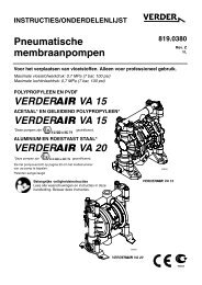
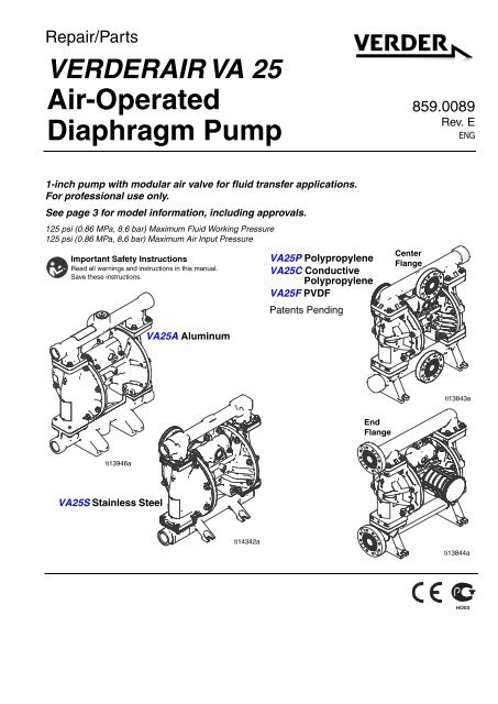
Repair/Parts<br />
VERDERAIR VA 25<br />
<strong>Air</strong>-<strong>Operated</strong><br />
<strong>Diaphragm</strong> <strong>Pump</strong><br />
859.0089<br />
Rev. E<br />
ENG<br />
1-inch pump with modular air valve for fluid transfer applications.<br />
For professional use only.<br />
See page 3 for model information, including approvals.<br />
125 psi (0.86 MPa, 8.6 bar) Maximum Fluid Working Pressure<br />
125 psi (0.86 MPa, 8.6 bar) Maximum <strong>Air</strong> Input Pressure<br />
Important Safety Instructions<br />
Read all warnings and instructions in this manual.<br />
Save these instructions.<br />
VA25P Polypropylene<br />
VA25C Conductive<br />
Polypropylene<br />
VA25F PVDF<br />
Patents Pending<br />
Center<br />
Flange<br />
VA25A Aluminum<br />
ti13843a<br />
End<br />
Flange<br />
ti13946a<br />
VA25S Stainless Steel<br />
ti14342a<br />
ti13844a
Contents<br />
Related Manuals . . . . . . . . . . . . . . . . . . . . . . . . . . . 2<br />
<strong>Pump</strong> Matrix . . . . . . . . . . . . . . . . . . . . . . . . . . . . . . 3<br />
ATEX Certifications . . . . . . . . . . . . . . . . . . . . . . . 3<br />
Warnings . . . . . . . . . . . . . . . . . . . . . . . . . . . . . . . . . 4<br />
Troubleshooting . . . . . . . . . . . . . . . . . . . . . . . . . . . 6<br />
Repair . . . . . . . . . . . . . . . . . . . . . . . . . . . . . . . . . . . . 8<br />
Pressure Relief Procedure . . . . . . . . . . . . . . . . . 8<br />
Repair or Replace <strong>Air</strong> Valve . . . . . . . . . . . . . . . . 8<br />
Check Valve Repair . . . . . . . . . . . . . . . . . . . . . 11<br />
<strong>Diaphragm</strong>s and Center Section . . . . . . . . . . . 12<br />
Torque Instructions . . . . . . . . . . . . . . . . . . . . . . 15<br />
Parts . . . . . . . . . . . . . . . . . . . . . . . . . . . . . . . . . . . . 16<br />
Parts/Kits Quick Reference . . . . . . . . . . . . . . . . 17<br />
Center Section . . . . . . . . . . . . . . . . . . . . . . . . . 18<br />
<strong>Air</strong> Valve and Data Monitoring . . . . . . . . . . . . . 20<br />
Fluid Covers and Manifolds . . . . . . . . . . . . . . . . 22<br />
Seats . . . . . . . . . . . . . . . . . . . . . . . . . . . . . . . . . 24<br />
Check Balls . . . . . . . . . . . . . . . . . . . . . . . . . . . . 24<br />
Seat, Check Ball, and <strong>Diaphragm</strong> Kits . . . . . . . 24<br />
<strong>Diaphragm</strong>s . . . . . . . . . . . . . . . . . . . . . . . . . . . . 26<br />
Manifold O-Rings . . . . . . . . . . . . . . . . . . . . . . . 28<br />
Accessories . . . . . . . . . . . . . . . . . . . . . . . . . . . 28<br />
Technical Data . . . . . . . . . . . . . . . . . . . . . . . . . . . . 30<br />
Customer Services/Guarantee . . . . . . . . . . . . . . . 33<br />
Related Manuals<br />
Manual<br />
Description<br />
859.0088 VERDERAIR VA 25 <strong>Air</strong>-<strong>Operated</strong> <strong>Diaphragm</strong> <strong>Pump</strong>, Operation<br />
859.0101 Torque Instructions (Manifolds and Fluid Covers)<br />
2 859.0089
PART NO.<br />
CONFIGURATION NO.<br />
DATE CODE SERIES MAX WPR PSI-bar MADE IN<br />
SERIAL NO.<br />
<strong>Pump</strong> Matrix<br />
Check the identification plate (ID) for the 20-digit part number of your pump. Use<br />
the following matrix to define the components of your pump. For example, pump<br />
number VA25A-A01AA1SSBNBNPT represents a 1 inch, 50 gpm aluminum<br />
pump (VA25A), with aluminum center section (A01), a standard air valve (A), aluminum<br />
fluid covers (A) and manifolds with standard ports in inches (1). The pump<br />
has stainless steel seats (SS), buna-N check balls (BN), buna-N diaphragms<br />
(BN), and PTFE manifold o-rings (PT).<br />
NOTE: Available options for seats, check balls, diaphragms, and seals vary based<br />
on pump model (VA25A-VA25S). To build a pump, use the selector tool at<br />
www.verder.com or speak with your distributor.<br />
<strong>Pump</strong><br />
(1 inch ports, 50 gpm)<br />
VA25A★<br />
Aluminum<br />
VA25C★<br />
Conductive Polypropylene<br />
VA25F<br />
PVDF<br />
VA25P<br />
Polypropylene<br />
VA25S‡<br />
Stainless Steel<br />
ATEX Certifications<br />
<strong>Pump</strong> ID<br />
Center Section and<br />
<strong>Air</strong> Valve Material <strong>Air</strong> Valve/Monitoring Fluid Covers and Manifolds<br />
Aluminum A01A Standard A1 Aluminum, standard ports, inch<br />
Conductive C01A Standard<br />
Polypropylene<br />
Polypropylene P01A Standard<br />
A2 Aluminum, standard ports, metric<br />
C1 Conductive polypropylene, center flange<br />
C2 Conductive polypropylene, end flange<br />
★, ‡, or ✖: See ATEX Certifications below.<br />
F1<br />
F2<br />
P1<br />
P2<br />
S1<br />
S2<br />
PVDF, center flange<br />
PVDF, end flange<br />
Polypropylene, center flange<br />
Polypropylene, end flange<br />
Stainless steel, standard ports, inch<br />
Stainless steel, standard ports, metric<br />
Check Valve Seats Check Valve Balls <strong>Diaphragm</strong> Manifold O-Rings<br />
AC<br />
AL<br />
Acetal<br />
Aluminum<br />
AC<br />
BN<br />
Acetal<br />
Buna-N<br />
BN<br />
CO<br />
Buna-N<br />
Polychloroprene Overmolded<br />
—<br />
PT<br />
None<br />
PTFE<br />
BN Buna-N<br />
CR Polychloroprene Standard FK FKM Fluoroelastomer<br />
FK FKM Fluoroelastomer CW Polychloroprene Weighted GE Geolast<br />
GE Geolast ®<br />
FK FKM Fluoroelastomer PO PTFE/EPDM Overmolded<br />
PP<br />
PV<br />
SP<br />
SS<br />
TP<br />
Polypropylene<br />
PVDF<br />
Santoprene ®<br />
316 Stainless Steel<br />
TPE<br />
GE<br />
PT<br />
SP<br />
SS<br />
TP<br />
Geolast<br />
PTFE<br />
Santoprene<br />
316 Stainless Steel<br />
TPE<br />
PT<br />
SP<br />
TP<br />
PTFE/EPDM Two-Piece<br />
Santoprene<br />
TPE<br />
ti14103a<br />
★ All VA25A (Aluminum) and<br />
VA25C (Conductive Polypropylene)<br />
pumps are certified:<br />
II 2 GD c IIC T4<br />
‡ VA25S (Stainless Steel) pumps<br />
with aluminum or conductive polypropylene<br />
centers are certified:<br />
II 2 GD c IIC T4<br />
✖ DataTrak and Pulse Count<br />
are certified:<br />
EEx ia IIA T3<br />
Nemko06ATEX1124<br />
II 1 G<br />
859.0089 3
Warnings<br />
The following warnings are for the setup, use, grounding, maintenance, and repair of this equipment. The exclamation<br />
point symbol alerts you to a general warning and the hazard symbol refers to procedure-specific risk. When<br />
these symbols appear in the body of this manual, refer back to these Warnings. Additional, product-specific warnings<br />
may be found throughout the body of this manual where applicable.<br />
WARNING<br />
FIRE AND EXPLOSION HAZARD<br />
Flammable fumes, such as solvent and paint fumes, in work area can ignite or explode. To help prevent<br />
fire and explosion:<br />
• Use equipment only in well ventilated area.<br />
• Eliminate all ignition sources; such as pilot lights, cigarettes, portable electric lamps, and plastic drop<br />
cloths (potential static arc).<br />
• Keep work area free of debris, including solvent, rags and gasoline.<br />
• Do not plug or unplug power cords, or turn power or light switches on or off when flammable fumes<br />
are present.<br />
• Ground all equipment in the work area. See Grounding instructions.<br />
• Use only grounded hoses.<br />
• Hold gun firmly to side of grounded pail when triggering into pail.<br />
• If there is static sparking or you feel a shock, stop operation immediately. Do not use equipment<br />
until you identify and correct the problem.<br />
• Keep a working fire extinguisher in the work area.<br />
Static charge may build up on plastic parts during cleaning and could discharge and ignite flammable<br />
materials and gases. To help prevent fire and explosion:<br />
• Clean plastic parts in a well ventilated area.<br />
• Do not clean with a dry cloth.<br />
• Do not operate electrostatic guns in equipment work area.<br />
EQUIPMENT MISUSE HAZARD<br />
Misuse can cause death or serious injury.<br />
• Do not operate the unit when fatigued or under the influence of drugs or alcohol.<br />
• Do not exceed the maximum working pressure or temperature rating of the lowest rated system<br />
component. See Technical Data in all equipment manuals.<br />
• Use fluids and solvents that are compatible with equipment wetted parts. See Technical Data in all<br />
equipment manuals. Read fluid and solvent manufacturer’s warnings. For complete information<br />
about your material, request MSDS from distributor or retailer.<br />
• Do not leave the work area while equipment is energized or under pressure. Turn off all equipment<br />
and follow the Pressure Relief Procedure in this manual when equipment is not in use.<br />
• Check equipment daily. Repair or replace worn or damaged parts immediately with genuine manufacturer’s<br />
replacement parts only.<br />
• Do not alter or modify equipment.<br />
• Use equipment only for its intended purpose. Call your distributor for information.<br />
• Route hoses and cables away from traffic areas, sharp edges, moving parts, and hot surfaces.<br />
• Do not kink or over bend hoses or use hoses to pull equipment.<br />
• Keep children and animals away from work area.<br />
• Comply with all applicable safety regulations.<br />
4 859.0089
WARNING<br />
PRESSURIZED EQUIPMENT HAZARD<br />
Fluid from the gun/dispense valve, leaks, or ruptured components can splash in the eyes or on skin and<br />
cause serious injury.<br />
• Follow Pressure Relief Procedure in this manual, when you stop spraying and before cleaning,<br />
checking, or servicing equipment.<br />
• Tighten all fluid connections before operating the equipment.<br />
• Check hoses, tubes, and couplings daily. Replace worn or damaged parts immediately.<br />
THERMAL EXPANSION HAZARD<br />
Fluids subjected to heat in confined spaces, including hoses, can create a rapid rise in pressure due to<br />
the thermal expansion. Over-pressurization can result in equipment rupture and serious injury.<br />
• Open a valve to relieve the fluid expansion during heating.<br />
• Replace hoses proactively at regular intervals based on your operating conditions.<br />
PRESSURIZED ALUMINUM PARTS HAZARD<br />
Use of fluids that are incompatible with aluminum in pressurized equipment can cause serious chemical<br />
reaction and equipment rupture. Failure to follow this warning can result in death, serious injury, or property<br />
damage.<br />
• Do not use 1,1,1-trichloroethane, methylene chloride, other halogenated hydrocarbon solvents or<br />
fluids containing such solvents.<br />
• Many other fluids may contain chemicals that can react with aluminum. Contact your material<br />
supplier for compatibility.<br />
PLASTIC PARTS CLEANING SOLVENT HAZARD<br />
Use only compatible water-based solvents to clean plastic structural or pressure-containing parts. Many<br />
solvents can degrade plastic parts and cause them to fail, which could cause serious injury or property<br />
damage. See Technical Data in this and all other equipment instruction manuals. Read fluid and solvent<br />
manufacturer’s warnings.<br />
TOXIC FLUID OR FUMES HAZARD<br />
Toxic fluids or fumes can cause serious injury or death if splashed in the eyes or on skin, inhaled, or<br />
swallowed.<br />
• Read MSDS’s to know the specific hazards of the fluids you are using.<br />
• Route exhaust away from work area. If diaphragm ruptures, fluid may be exhausted with air.<br />
• Store hazardous fluid in approved containers, and dispose of it according to applicable guidelines.<br />
• Always wear impervious gloves when spraying or cleaning equipment.<br />
BURN HAZARD<br />
Equipment surfaces and fluid that’s heated can become very hot during operation. To avoid severe<br />
burns:<br />
• Do not touch hot fluid or equipment.<br />
• Wait until equipment/fluid has cooled completely.<br />
PERSONAL PROTECTIVE EQUIPMENT<br />
You must wear appropriate protective equipment when operating, servicing, or when in the operating<br />
area of the equipment to help protect you from serious injury, including eye injury, inhalation of toxic<br />
fumes, burns, and hearing loss. This equipment includes but is not limited to:<br />
• Clothing and respirator as recommended by the fluid and solvent manufacturer<br />
• Protective eyewear, gloves, and hearing protection.<br />
859.0089 5
Troubleshooting<br />
Problem Cause Solution<br />
<strong>Pump</strong> cycles but will not prime. Check valve ball severely worn or Replace ball and seat. See page 11.<br />
wedged in seat or manifold.<br />
Seat severely worn. Replace ball and seat. See page 11.<br />
Outlet or inlet clogged.<br />
Unclog.<br />
Inlet or outlet valve closed.<br />
Open.<br />
Inlet fittings or manifolds loose. Tighten.<br />
Manifold o-rings damaged. Replace o-rings. See page 11.<br />
<strong>Pump</strong> cycles at stall or fails to hold<br />
pressure at stall.<br />
<strong>Pump</strong> will not cycle, or cycles once<br />
and stops.<br />
Worn check valve balls, seats, or Replace. See page 24.<br />
o-rings.<br />
<strong>Air</strong> valve is stuck or dirty.<br />
Disassemble and clean air valve. See<br />
page 9. Use filtered air.<br />
Check valve ball severely worn and Replace ball and seat. See page 11.<br />
wedged in seat or manifold.<br />
Pilot valve worn, damaged, or Replace pilot valve. See page 12.<br />
plugged.<br />
<strong>Air</strong> valve gasket damaged. Replace gasket. See page 8.<br />
Check valve ball is wedged into seat<br />
due to overpressurization.<br />
Dispensing valve clogged.<br />
Install pressure relief kit. See Accessories,<br />
page 28.<br />
Relieve pressure and clear valve.<br />
<strong>Pump</strong> operates erratically. Clogged suction line. Inspect; clear.<br />
Sticky or leaking check valve balls. Clean or replace. See page 11.<br />
<strong>Diaphragm</strong> (and backup) ruptured. Replace. See page 12.<br />
Restricted exhaust.<br />
Remove restriction.<br />
Pilot valves damaged or worn. Replace pilot valves. See page 12.<br />
<strong>Air</strong> valve damaged. Replace air valve. See page 8.<br />
<strong>Air</strong> valve gasket damaged.<br />
Replace air valve gasket. See<br />
page 8.<br />
<strong>Air</strong> supply erratic.<br />
Repair air supply.<br />
Exhaust muffler icing.<br />
Use drier air supply or use low ice<br />
muffler (Verder part 819.7000).<br />
<strong>Air</strong> bubbles in fluid. Suction line is loose. Tighten.<br />
<strong>Diaphragm</strong> (and backup) ruptured. Replace. See page 12.<br />
Loose manifolds, damaged seats or<br />
manifold o-rings.<br />
<strong>Diaphragm</strong> shaft bolt o-ring damaged.<br />
<strong>Pump</strong> cavitation.<br />
Loose diaphragm shaft bolt.<br />
Tighten manifold bolts or replace<br />
seats or o-rings. See page 11.<br />
Replace o-ring.<br />
Reduce pump speed or suction lift.<br />
Tighten.<br />
6 859.0089
Problem Cause Solution<br />
Exhaust air contains fluid being <strong>Diaphragm</strong> (and backup) ruptured. Replace. See page 12.<br />
pumped.<br />
Loose diaphragm shaft bolt. Tighten or replace. See page 12.<br />
<strong>Diaphragm</strong> shaft bolt o-ring damaged.<br />
Replace o-ring. See page 12.<br />
Moisture in exhaust air. High inlet air humidity. Use drier air supply.<br />
<strong>Pump</strong> exhausts excessive air at stall. Worn air valve cup or plate. Replace cup and plate. See page 9.<br />
Damaged air valve gasket. Replace gasket. See page 8.<br />
Damaged pilot valve. Replace pilot valves. See page 12.<br />
Worn shaft seals or bearings. Replace shaft seals or bearings. See<br />
page 12.<br />
<strong>Pump</strong> leaks air externally. <strong>Air</strong> valve or fluid cover screws loose. Tighten.<br />
<strong>Diaphragm</strong> damaged. Replace diaphragm. See page 12.<br />
<strong>Air</strong> valve gasket damaged. Replace gasket. See page 8.<br />
<strong>Pump</strong> leaks fluid externally from<br />
joints.<br />
<strong>Pump</strong> leaks fluid externally through<br />
manifold or fluid cover.<br />
Loose manifold screws or fluid cover<br />
screws.<br />
Tighten manifold screws or fluid<br />
cover screws. See page 15.<br />
Manifold o-rings worn out. Replace o-rings. See page 11.<br />
Excessive pump speed or inlet<br />
starvation.<br />
Replace manifold and reduce pump<br />
speed or improve pump feed.<br />
859.0089 7
Repair<br />
Pressure Relief Procedure<br />
4. For motors with DataTrak: Remove two screws<br />
and the solenoid bracket. Pull the solenoid out of the<br />
air valve.<br />
Trapped air can cause the pump to cycle unexpectedly,<br />
which could result in serious injury from splashing.<br />
1. Shut off the air supply to the pump.<br />
2. Open the dispensing valve, if used.<br />
3. Open the fluid drain valve to relieve fluid pressure.<br />
Have a container ready to catch the drainage.<br />
Aluminum Model<br />
Shown<br />
109<br />
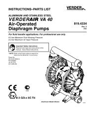
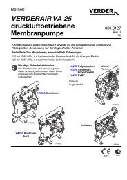
Repair or Replace <strong>Air</strong> Valve<br />
Replace Complete <strong>Air</strong> Valve<br />
1. Stop the pump. Relieve the pressure. See Pressure<br />
Relief Procedure in previous section.<br />
FIG. 2. Solenoid removal<br />
ti14095a<br />
2. Disconnect the air line to the motor.<br />
3. For motors with Pulse Count or DataTrak:<br />
Remove screw to disconnect the reed switch<br />
assembly from the air valve.<br />
5. Remove screws (109, metal pumps) or nuts (112,<br />
plastic pumps). Remove the air valve and gasket<br />
(108).<br />
6. To repair the air valve, go to Disassemble the <strong>Air</strong><br />
Valve, step 1, in next section. To install a replacement<br />
air valve, continue with step 7.<br />
7. Align the new air valve gasket (108) on the center<br />
housing, then attach the air valve. See Torque<br />
Instructions, page 15.<br />
8. For motors with DataTrak: Remember to reattach<br />
the solenoid bracket and the solenoid.<br />
9. For motors with Pulse Count or DataTrak: Use<br />
screw to attach the reed switch assembly to the new<br />
air valve. Reconnect cable.<br />
ti14094a<br />
FIG. 1. Reed switch assembly and air line removal<br />
10. Reconnect the air line to the motor.<br />
8 859.0089
Replace Seals or Rebuild <strong>Air</strong> Valve<br />
NOTE: Repair kits are available. See page 20 to order<br />
the correct kit(s) for your pump. <strong>Air</strong> Valve Seal Kit parts<br />
are marked with a †. <strong>Air</strong> Valve Repair Kit parts are<br />
marked with a ◆. <strong>Air</strong> Valve End Cap Kit parts are marked<br />
with a ✠.<br />
Disassemble the <strong>Air</strong> Valve<br />
1. Perform steps 1-5 under Replace Complete <strong>Air</strong><br />
Valve, page 8.<br />
2. See FIG. 4. Use a Torx screwdriver (T8 for aluminum<br />
centers, T9 for plastic centers) to remove two screws<br />
(209). Remove the valve plate (205),<br />
cup (212), spring (211), and detent assembly (203).<br />
3. See FIG. 4. Remove the retaining ring (210) from<br />
each end of the air valve. Use the piston (202) to<br />
push the end caps (207, 217) out of the ends.<br />
Remove end cap o-rings (206). If pump model is<br />
equipped with a runaway protection solenoid, also<br />
remove the solenoid release button (218) and<br />
o-ring (219).<br />
4. Remove the u-cup seals (208) from each end of the<br />
piston (202), then remove the piston. Remove the<br />
detent cam (204) from the air valve housing (201).<br />
Reassemble the <strong>Air</strong> Valve<br />
NOTE: Apply lithium-based grease whenever instructed<br />
to grease.<br />
1. Use all parts in the repair kits. Clean other parts and<br />
inspect for damage. Replace as needed.<br />
2. Grease the detent cam (204) and install into housing<br />
(201).<br />
3. Grease the u-cups (208) and install on the piston with<br />
lips facing toward the center of the piston.<br />
208◆†<br />
Lips face down<br />
202◆<br />
208◆†<br />
Lips face up<br />
FIG. 3. <strong>Air</strong> valve u-cup installation<br />
ti12754a<br />
859.0089 9
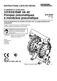
210✠<br />
206◆†✠ 1<br />
207✠<br />
210✠<br />
201<br />
206◆†✠ 1<br />
217✠<br />
219✠<br />
DataTrak Models<br />
with Runaway 218✠<br />
Protection<br />
air<br />
inlet<br />
1 204◆<br />
1 203◆<br />
208◆†<br />
1 2<br />
202◆ 1<br />
208◆† 1 2<br />
207✠<br />
206◆†✠ 1<br />
210✠<br />
211◆<br />
1 212◆<br />
1<br />
2<br />
Apply lithium-based grease.<br />
U-cup lips must face piston.<br />
205◆<br />
209◆†<br />
ti14026a<br />
FIG. 4. <strong>Air</strong> valve assembly<br />
4. Grease both ends of the piston (202) and install it in<br />
the housing (201), with the flat side toward the cup<br />
(212). Be careful not to tear u-cups (208) when sliding<br />
piston into housing.<br />
5. Standard or Pulse Count models (no runaway<br />
protection solenoid): Grease new o-rings (206)<br />
and install on the end caps (207). Install the end<br />
caps into the housing.<br />
DataTrak models (with runaway protection solenoid):<br />
Orient the air valve so the air inlet faces forward.<br />
Grease and install new o-ring (206) on<br />
right-side end cap (207). Grease and install new<br />
o-ring (206) and the solenoid release button (218)<br />
and o-ring (219) on left-side end cap (217). Install<br />
the end caps into the housing.<br />
6. Install a retaining ring (210) on each end to hold end<br />
caps in place.<br />
7. Grease and install the detent assembly (203) into<br />
the piston. Install the spring (211). Grease the side<br />
of the air valve cup (212) that will contact the valve<br />
plate (205). Install the air valve cup (212). Align the<br />
small round magnet with the air inlet.<br />
8. Install the valve plate (205). Align the small hole in<br />
the plate with the air inlet. Tighten the screws (209)<br />
to hold it in place.<br />
205<br />
small<br />
hole<br />
212<br />
magnet<br />
ti14097a<br />
FIG. 5. <strong>Air</strong> valve cup and plate installation<br />
10 859.0089
Check Valve Repair<br />
1<br />
2<br />
Torque to 100 in-lb (11.3 N•m). See Torque Instructions,<br />
page 15.<br />
Arrow (A) must point toward outlet manifold.<br />
NOTE: Kits are available for new check valve balls and<br />
seats in a range of materials. See page 24 to order kits in<br />
the material(s) desired. An o-ring kit and fastener kits<br />
also are available.<br />
3<br />
Not used on some models.<br />
Aluminum pump<br />
shown<br />
6<br />
1<br />
NOTE: To ensure proper seating of the check balls,<br />
always replace the seats when replacing the balls. Also,<br />
on models with manifold o-rings, replace the o-rings.<br />
4<br />
Disassembly<br />
1. Follow the Pressure Relief Procedure on page 8.<br />
Disconnect all hoses.<br />
11<br />
2. Remove the pump from its mounting.<br />
12<br />
3<br />
3. Use a 10 mm socket wrench to remove the outlet<br />
manifold fasteners (6). See FIG. 6.<br />
NOTE: For plastic pumps (VA25C, VA25P, and<br />
VA25F), use hand tools only until thread-locking<br />
adhesive patch releases.<br />
4. Remove the o-rings (12, not used on some models),<br />
seats (10), and balls (11).<br />
5. Turn the pump over and remove the inlet manifold.<br />
Remove the o-rings (12, not used on some models),<br />
seats (10), and balls (11).<br />
10<br />
12 3<br />
3<br />
A 2<br />
7<br />
Reassembly<br />
1. Clean all parts and inspect for wear or damage.<br />
Replace parts as needed.<br />
2. Reassemble in the reverse order, following all notes<br />
in FIG. 6. Be sure the ball checks (10-12) and manifolds<br />
(4, 5) are assembled exactly as shown. The<br />
arrows (A) on the fluid covers must point toward the<br />
outlet manifold (4).<br />
11<br />
12<br />
10<br />
12<br />
3<br />
3<br />
5<br />
1 6<br />
FIG. 6. Ball check valve assembly<br />
ti14098a<br />
859.0089 11
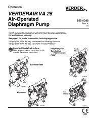
<strong>Diaphragm</strong>s and Center Section<br />
Disassembly<br />
NOTE: <strong>Diaphragm</strong> kits are available in a range of materials<br />
and styles. See page 26 to order the correct diaphragms<br />
for your pump. A Center Rebuild Kit also is<br />
available. See page 19. Parts included in the Center<br />
Rebuild Kit are marked with an *. For best results, use<br />
all kit parts.<br />
1. Follow the Pressure Relief Procedure on page 8.<br />
2. Remove the manifolds and disassemble the ball<br />
check valves as explained on page 11.<br />
3. Overmolded <strong>Diaphragm</strong>s<br />
a. Orient the pump so one of the fluid covers faces<br />
up. Use a 10 mm socket wrench to remove the<br />
fluid cover screws (7), then pull the fluid cover<br />
(3) up off the pump.<br />
b. The exposed diaphragm (15) will screw off by<br />
hand from the diaphragm shaft (104). The diaphragm<br />
shaft bolt will remain attached to the<br />
diaphragm. Remove the air side diaphragm<br />
plate (14).<br />
b. Plastic <strong>Pump</strong>s: Use a 1-1/4 socket or box end<br />
wrench on the hex of a fluid side diaphragm<br />
plate to remove. Then remove all parts of the<br />
diaphragm assembly. See FIG. 7.<br />
Metal <strong>Pump</strong>s: Remove the bolt (304) from one<br />
side of the diaphragm shaft, then remove all<br />
parts of that diaphragm assembly. See FIG. 7.<br />
c. Follow the same procedure to disassemble the<br />
other diaphragm assembly.<br />
5. Inspect the diaphragm shaft (104) for wear or<br />
scratches. If it is damaged, inspect the bearings<br />
(105) in place. If they are damaged, use a bearing<br />
puller to remove them.<br />
NOTE: Do not remove undamaged bearings.<br />
6. Use an o-ring pick to remove the u-cup packings<br />
(106) from the center housing. Bearings (105) can<br />
remain in place.<br />
7. Use a socket wrench to remove the pilot valves<br />
(101).<br />
8. Remove the pilot valve cartridges only if necessary<br />
due to a known or suspected problem. After removing<br />
pilot valves, use a hex to remove the cartridges<br />
(102), then remove o-rings (103). If stripped, use<br />
two screwdrivers to screw out the cartridge.<br />
NOTE: Do not remove undamaged pilot valve<br />
cartridges.<br />
c. Turn the pump over and remove the other fluid<br />
cover. Pull the diaphragm and shaft up through<br />
the center housing.<br />
d. Grasp the diaphragm firmly and use a wrench<br />
on the flats of the shaft to remove. Also remove<br />
the air side diaphragm plate (14). Continue with<br />
Step 5.<br />
4. All Other <strong>Diaphragm</strong>s<br />
a. Orient the pump so one of the fluid covers faces<br />
up. Use a 10 mm socket wrench to remove the<br />
fluid cover screws (7), then pull the fluid cover<br />
up off the pump. Turn the pump over and<br />
remove the other fluid cover.<br />
12 859.0089
104* 2<br />
14<br />
1<br />
15<br />
14 1 303 5<br />
4<br />
15 4<br />
13<br />
1<br />
301<br />
TP, SP, BN,<br />
FK, and GE<br />
models<br />
3<br />
304<br />
(Metal pumps)<br />
13<br />
(Plastic pumps) ti14022a<br />
3<br />
104*<br />
2<br />
PO and<br />
CO models<br />
ti14037a<br />
1<br />
2<br />
3<br />
4<br />
5<br />
Rounded side faces diaphragm.<br />
Apply lithium-based grease.<br />
Torque to 20-25 ft-lb (27-34 N•m)<br />
at 100 rpm maximum.<br />
AIR SIDE markings on diaphragm<br />
must face center housing.<br />
If screw comes loose or is<br />
replaced, apply permanent (red)<br />
Loctite ® or equivalent to<br />
diaphragm side threads. Apply<br />
primer and medium-strength (blue)<br />
Loctite ® or equivalent to shaft side<br />
threads.<br />
2<br />
104*<br />
1<br />
14<br />
PT models<br />
305<br />
4<br />
15<br />
4<br />
13 1<br />
301<br />
304 3<br />
(Metal pumps)<br />
6<br />
7<br />
8<br />
Lips must face out of housing.<br />
Cartridges (102) must be installed in<br />
housing before pilot valves (101).<br />
Torque to 20-25 in.-lb (2.3-2.8 N•m).<br />
3<br />
13 (Plastic pumps)<br />
ti14021a<br />
2 105*<br />
6 2 106*<br />
7 2 102*<br />
2 103*<br />
103* 2<br />
106* 2<br />
6<br />
2<br />
7<br />
8<br />
101*<br />
110<br />
7 2 102*<br />
2<br />
105*<br />
FIG. 7. Assemble diaphragms and center section<br />
2<br />
104*<br />
ti14025b<br />
859.0089 13
Reassembly<br />
Follow all notes in FIG. 7. These notes contain<br />
important information.<br />
NOTE: Apply lithium-based grease whenever instructed<br />
to grease.<br />
1. Clean all parts and inspect for wear or damage.<br />
Replace parts as needed.<br />
2. If removed, grease and install the new pilot valve<br />
cartridges (102) and o-rings (103). Screw in until<br />
seated.<br />
NOTE: Cartridges (102) must be installed before pilot<br />
valves (101).<br />
3. Grease and install the pilot valves (101). Torque to<br />
20-25 in.-lb (2.3-2.8 N•m). Do not over-torque.<br />
4. Grease and install the diaphragm shaft u-cup packings<br />
(106) so the lips face out of the housing.<br />
5. If removed, insert the new bearings (105) into the<br />
center housing. Use a press or a block and rubber<br />
mallet to press-fit the bearing so it is flush with the<br />
surface of the center housing.<br />
6. Overmolded <strong>Diaphragm</strong>s:<br />
a. Clamp the shaft flats in a vise.<br />
b. If diaphragm setscrew comes loose or is<br />
replaced, apply permanent (red) Loctite ® or<br />
equivalent to diaphragm side threads. Screw<br />
into diaphragm until tight.<br />
c. Assemble the air side plate (14) onto the diaphragm.<br />
The rounded side of the plate must<br />
face the diaphragm.<br />
d. Apply medium-strength (blue) Loctite or equivalent<br />
to the threads of the diaphragm assembly.<br />
Screw the assembly into the shaft as tight as<br />
possible by hand.<br />
e. Grease the shaft u-cups (106) and the length<br />
and ends of the diaphragm shaft (104). Slide the<br />
shaft into the housing.<br />
f. Reattach the first fluid cover (3). See Torque<br />
Instructions, page 15.<br />
All Other <strong>Diaphragm</strong>s - Metal <strong>Pump</strong>s:<br />
a. Install the o-ring (301) on the shaft bolt (304).<br />
b. Assemble the fluid side plate (13), the diaphragm<br />
(15), the backup diaphragm (305, if<br />
present), and the air side diaphragm plate (14)<br />
on the bolt exactly as shown in FIG. 7.<br />
c. Apply medium-strength (blue) Loctite or equivalent<br />
to the bolt (304) threads. Screw the bolt into<br />
the shaft hand tight.<br />
d. Grease the shaft u-cups (106) and the length<br />
and ends of the diaphragm shaft (104). Slide the<br />
shaft into the housing.<br />
e. Repeat Steps a-c for the other diaphragm<br />
assembly.<br />
f. Hold one shaft bolt with a wrench and torque<br />
the other bolt to 20-25 ft-lb (27-34 N•m) at 100<br />
rpm maximum. Do not over-torque.<br />
g. Reattach the first fluid cover (3). See Torque<br />
Instructions, page 15. Go to Step 7.<br />
All Other <strong>Diaphragm</strong>s - Plastic <strong>Pump</strong>s:<br />
a. Assemble the diaphragm (15), the backup diaphragm<br />
(305, if present), and the air side diaphragm<br />
plate (14) on the fluid side plate (13)<br />
exactly as shown in FIG. 7.<br />
b. Apply medium-strength (blue) Loctite or equivalent<br />
to the threads of the screw on the fluid side<br />
plate. Screw the assembly into the shaft<br />
hand-tight.<br />
c. Grease the shaft u-cups (106) and the length<br />
and ends of the diaphragm shaft (104). Slide the<br />
shaft into the housing.<br />
d. Repeat for the other diaphragm assembly<br />
e. Hold one of the plates with a wrench, and<br />
torque the other plate to 20-25 ft-lb (27-34 N•m)<br />
at 100 rpm maximum. Do not over-torque.<br />
f. Reattach the first fluid cover (3). See Torque<br />
Instructions, page 15.<br />
g. Repeat Steps b and c for the other diaphragm<br />
assembly. Go to Step 7.<br />
14 859.0089
7. To ensure proper seating and extend diaphragm life,<br />
attach the second fluid cover with air pressure on the<br />
pump.<br />
a. See FIG. 8. Place the supplied tool (302) where<br />
the air valve gasket (108) normally goes. Arrows<br />
(A) must face toward the fluid cover that is<br />
already attached.<br />
302 A<br />
Torque Instructions<br />
NOTE: Fluid cover and manifold fasteners have a<br />
thread-locking adhesive patch applied to the threads. If<br />
this patch is excessively worn, the screws may loosen<br />
during operation. Replace screws with new ones, or<br />
apply medium-strength (blue) Loctite or equivalent to the<br />
threads.<br />
If fluid cover or manifold fasteners have been loosened, it<br />
is important to torque them using the following procedure<br />
to improve sealing.<br />
NOTE: Always completely torque fluid covers before<br />
torquing manifolds.<br />
FIG. 8. Fluid cover tool<br />
b. Reattach the air valve.<br />
ti14120a<br />
Start all fluid cover screws a few turns. Then turn down<br />
each screw just until head contacts cover. Then turn each<br />
screw by 1/2 turn or less working in a crisscross pattern<br />
to specified torque. Repeat for manifolds.<br />
Fluid cover and manifold fasteners:<br />
100 in-lb (11.3 N•m)<br />
Retorque the air valve fasteners (V) in a crisscross pattern<br />
to specified torque.<br />
Plastic center sections: 55 in-lb (6.2 N•m)<br />
Metal center sections: 80 in-lb (9.0 N•m)<br />
c. Supply a minimum of 20 psi (0.14 MPa, 1.4 bar)<br />
air pressure to the air valve. Shop air may be<br />
used. The diaphragm will shift so the second fluid<br />
cover will seat properly. Keep air pressure on<br />
until the second fluid cover is attached.<br />
1<br />
8<br />
3<br />
5<br />
d. Attach the second fluid cover (3). See Torque<br />
Instructions, page 15.<br />
e. Remove the air valve and the tool (302), replace<br />
the gasket (108), and reattach the air valve. See<br />
Torque Instructions, page 15.<br />
NOTE: If you are replacing the diaphragms but not the air<br />
valve, you must remove the air valve and gasket, put the<br />
tool in place of the gasket, and put the air valve back on<br />
to get the air pressure needed for proper installation of<br />
the second fluid cover. Remember to remove the tool and<br />
replace the gasket when finished.<br />
6<br />
4<br />
13<br />
9<br />
ti13845a<br />
7<br />
2<br />
12 16<br />
8. Reassemble the ball check valves and manifolds as<br />
explained on page 11.<br />
15<br />
11<br />
FIG. 9. Torque sequence<br />
V<br />
10<br />
ti13846a<br />
14<br />
859.0089 15
Parts<br />
8<br />
1<br />
9<br />
6<br />
4<br />
18<br />
11<br />
1<br />
10<br />
13<br />
2<br />
3<br />
15<br />
7<br />
12<br />
1<br />
5<br />
1 Not used on some models.<br />
ti14023a<br />
16 859.0089
Parts/Kits Quick Reference<br />
Use this table as a quick reference for parts/kits. See pages indicated in table for full description of kit contents.<br />
Ref. Part/Kit Description Qty.<br />
1 Varies Center Section; not sold separately, see 1<br />
page 18<br />
Aluminum<br />
Conductive Polypropylene<br />
Polypropylene<br />
2 Varies <strong>Air</strong> Valve; see page 20 1<br />
3<br />
859.0032<br />
859.0071<br />
859.0070<br />
859.0072<br />
859.0081<br />
Fluid Cover Kits; see page 22<br />
Aluminum<br />
Conductive Polypropylene<br />
Polypropylene<br />
PVDF<br />
Stainless Steel<br />
2<br />
4<br />
5<br />
6<br />
7<br />
8<br />
859.0028<br />
859.0029<br />
859.0059<br />
859.0062<br />
859.0058<br />
859.0061<br />
859.0060<br />
859.0063<br />
859.0077<br />
859.0078<br />
859.0030<br />
859.0031<br />
859.0065<br />
859.0068<br />
859.0064<br />
859.0067<br />
859.0066<br />
859.0069<br />
859.0079<br />
859.0080<br />
859.0033<br />
859.0076<br />
859.0084<br />
859.0033<br />
859.0075<br />
859.0083<br />
859.0076<br />
859.0105<br />
859.0106<br />
Outlet Manifold Kits; see page 23<br />
Aluminum, npt<br />
Aluminum, bspt<br />
Conductive Poly, center flange<br />
Conductive Poly, end flange<br />
Polypropylene, center flange<br />
Polypropylene, end flange<br />
PVDF, center flange<br />
PVDF, end flange<br />
Stainless Steel, npt<br />
Stainless Steel, bspt<br />
Inlet Manifold Kits; see page 23<br />
Aluminum, npt<br />
Aluminum, bspt<br />
Conductive Poly, center flange<br />
Conductive Poly, end flange<br />
Polypropylene, center flange<br />
Polypropylene, end flange<br />
PVDF, center flange<br />
PVDF, end flange<br />
Stainless Steel, npt<br />
Stainless Steel, bspt<br />
Manifold Fasteners; 8-pack, see page 22<br />
Aluminum<br />
Conductive Polypropylene, Polypropylene,<br />
and PVDF<br />
Stainless Steel<br />
Fluid Cover Fasteners; 8-pack,<br />
see page 22<br />
Aluminum<br />
Conductive Polypropylene, Polypropylene,<br />
and PVDF<br />
Stainless Steel, aluminum<br />
center<br />
Stainless Steel, plastic center<br />
Plug, 1 in.; 6-pack, aluminum pumps only<br />
npt<br />
bspt<br />
9 859.0102 Pressure Relief Valve; fuel dispense<br />
model only, see page 22<br />
1<br />
1<br />
16<br />
16<br />
6<br />
1<br />
Ref. Part/Kit Description Qty.<br />
10<br />
11<br />
859.0009<br />
859.0010<br />
859.0011<br />
859.0017<br />
859.0012<br />
859.0014<br />
859.0087<br />
859.0015<br />
859.0016<br />
859.0013<br />
859.0018<br />
859.0019<br />
859.0022<br />
859.0023<br />
859.0027<br />
859.0020<br />
859.0024<br />
859.0025<br />
859.0026<br />
859.0021<br />
Seats; 4-pack, includes 8 o-rings where<br />
needed, see page 24<br />
Acetal<br />
Aluminum<br />
Buna-N<br />
FKM Fluoroelastomer<br />
Geolast<br />
Polypropylene<br />
PVDF<br />
Santoprene<br />
Stainless Steel<br />
TPE<br />
Check Balls; 4-pack, includes 8 o-rings,<br />
see page 24<br />
Acetal<br />
Buna-N<br />
Neoprene<br />
Neoprene with SST core<br />
FKM Fluoroelastomer<br />
Geolast<br />
PTFE<br />
Santoprene<br />
Stainless Steel<br />
TPE<br />
12 859.0034 Manifold O-Ring (not used on some models);<br />
ptfe, 8-pack, see page 28<br />
13<br />
859.0055<br />
859.0056<br />
859.0056<br />
859.0057<br />
859.0082<br />
Fluid Side <strong>Diaphragm</strong> Plate; included in<br />
<strong>Air</strong> and Fluid Plate Kits, see page 27<br />
Aluminum<br />
Conductive Polypropylene<br />
Polypropylene<br />
PVDF<br />
Stainless Steel<br />
14 ----- <strong>Air</strong> Side <strong>Diaphragm</strong> Plate (not visible);<br />
included in <strong>Air</strong> and Fluid Plate Kits, see<br />
Part 13 or page 27<br />
15<br />
859.0001<br />
859.0008<br />
859.0002<br />
859.0007<br />
859.0003<br />
859.0004<br />
859.0005<br />
859.0006<br />
<strong>Diaphragm</strong> Kits; see page 26<br />
Buna-N Standard<br />
FKM Fluoroelastomer Standard<br />
Geolast Standard<br />
Santoprene Standard<br />
TPE Standard<br />
Neoprene Overmolded<br />
PTFE Overmolded<br />
PTFE/EPDM Two-Piece<br />
18 819.4376 Muffler; 3/4 npt, plastic 1<br />
19<br />
Screw, ground, M5 x 0.8; not shown 1<br />
819.0220<br />
819.0221<br />
Aluminum pumps, carbon steel<br />
Conductive Poly <strong>Pump</strong>s, stainless<br />
steel<br />
20▲ 819.4313 Label, warning (not shown) 1<br />
▲Replacement Warning labels, signs, tags, and cards<br />
are available at no cost.<br />
4<br />
4<br />
8<br />
2<br />
2<br />
2<br />
859.0089 17
Center Section<br />
<strong>Pump</strong> Size<br />
and Material<br />
Fluid Covers<br />
and Manifolds<br />
Seats<br />
Check<br />
Balls<br />
<strong>Diaphragm</strong><br />
Manifold<br />
O-Rings<br />
VA25A XXXX A2 AL BN TP PT<br />
Aluminum Center Section<br />
(A01x, AC1x, AU1x, and<br />
AU3x)<br />
air valve<br />
detail, see<br />
page 20<br />
Plastic Center Section<br />
(C01x and P01x)<br />
109*<br />
*112<br />
2<br />
2<br />
*105<br />
108*<br />
*106<br />
*102<br />
*103 103*<br />
*108<br />
*101<br />
*102<br />
110 *106<br />
110<br />
*105<br />
*104<br />
ti14025a<br />
ti14104a<br />
Ref. Description Qty.<br />
101* VALVE, pilot 2<br />
102* CARTRIDGES, pilot valve receiver 2<br />
103* O-RING, receiver cartridge 2<br />
104* SHAFT, center 1<br />
105* BEARING, center shaft 2<br />
106* U-CUP, center shaft 2<br />
108* GASKET, air valve 1<br />
109* SCREW, M6 x 25, stainless steel, (for 4<br />
aluminum center section models, Axxx)<br />
110 HOUSING, center, not sold separately 1<br />
112* NUTS (for plastic center section models, 4<br />
C01x and P01x)<br />
* Included in Center Section Rebuild Kit 859.0000.<br />
18 859.0089
Kit 859.0000, Center Section Rebuild (*)<br />
All Models<br />
Kit includes:<br />
• 2 pilot valves (101)<br />
• 2 pilot cartridges (102)<br />
• 2 cartridge o-rings, buna-N (103)<br />
• 1 center shaft (104)<br />
• 2 center shaft bearings (105)<br />
• 2 center shaft u-cups (106)<br />
• 1 air valve gasket (108)<br />
• 4 bolts, M6 x 25, for A01x pumps (109)<br />
• 4 nuts, for P01x and C01x pumps (112)<br />
• 8 o-rings, PTFE (12)<br />
Kit 859.0036, Pilot Valves w/Cartridges<br />
All models<br />
Kit includes:<br />
• 2 pilot valve assemblies (101)<br />
• 2 pilot valve receiver cartridges (102)<br />
• 2 receiver cartridge o-rings (103)<br />
Kit 859.0116, Pilot Valves<br />
All models<br />
Kit includes:<br />
• 2 pilot valve assemblies (101)<br />
Kit 859.0035, Center Shaft Kit<br />
All models<br />
Kit includes:<br />
• 1 center shaft (104)<br />
• 2 center shaft bearings (105)<br />
• 2 center shaft u-cups (106)<br />
Kit 859.0037, Center Shaft Bearing Kit<br />
All models<br />
Kit includes:<br />
• 2 center shaft bearings (105)<br />
• 2 center shaft u-cups (106)<br />
The center housing (110) is not sold separately.<br />
Ground Screws<br />
Ground<br />
Center Section Material<br />
Screw (19)<br />
A01A, A01B, Aluminum 819.0220<br />
A01C, AU1A,<br />
AU3A, and AC1A<br />
C01A, C01B Conductive 819.0221<br />
C01C<br />
Polypropylene<br />
P01A, P01B<br />
P01C<br />
Polypropylene None<br />
859.0089 19
<strong>Air</strong> Valve and Data Monitoring<br />
208◆†<br />
202◆<br />
201<br />
Standard (no reed switch) or<br />
Pulse Count (with reed switch)<br />
220<br />
210✠<br />
206◆†✠<br />
207✠<br />
208◆†<br />
207✠<br />
206◆†✠<br />
210✠<br />
201<br />
(Compatible with DataTrak<br />
with runaway protection)<br />
◆204<br />
◆203<br />
◆211<br />
219◆†✠<br />
206◆†✠<br />
◆212<br />
◆205<br />
◆†209<br />
218✠<br />
217✠<br />
210✠<br />
ti14027a<br />
Ref. Description Qty.<br />
201 HOUSING, not sold separately 1<br />
202◆ PISTON 1<br />
203◆ DETENT PISTON ASSEMBLY 1<br />
204◆ CAM, detent 1<br />
205◆ PLATE, air valve 1<br />
206◆†✠ O-RING 2<br />
207✠<br />
CAP, end<br />
Standard (xxxA) or Pulse Count (xxxB)<br />
DataTrak (xxxC)<br />
208◆† U-CUP 2<br />
209◆† SCREW 2<br />
210◆✠ RETAINING RING 2<br />
211◆ DETENT SPRING 1<br />
212◆ CUP 1<br />
217✠ CAP, end (for DataTrak models with runaway 1<br />
protection, xxxC)<br />
218✠ BUTTON, solenoid release (for DataTrak 1<br />
models with runaway protection, xxxC)<br />
219◆†✠ O-RING (for DataTrak models with runaway 1<br />
protection, xxxC)<br />
220 REED SWITCH ASSEMBLY (for Pulse<br />
Count models, xxxB, includes fastener)<br />
1<br />
◆Parts included in <strong>Air</strong> Valve Repair Kit 859.0040.<br />
† Parts included in <strong>Air</strong> Valve Seals Kit 859.0041.<br />
✠ Parts included in <strong>Air</strong> Valve End Cap Kit. See page 21.<br />
2<br />
1<br />
Kit 859.0040, <strong>Air</strong> Valve Repair (◆)<br />
All Models<br />
Kit includes:<br />
• 1 air valve piston (202)<br />
• 1 detent piston assembly (203)<br />
• 1 detent cam (204)<br />
• 1 air valve plate (205)<br />
• 2 end cap o-rings (206)<br />
• 2 piston u-cups (208)<br />
• 2 screws, M3, shorter (209, for metal pumps)<br />
• 2 screws, #4, longer (209, for plastic pumps)<br />
• 1 detent spring (211)<br />
• 1 air cup (212)<br />
• 1 solenoid release button o-ring (219)<br />
• 1 air valve gasket (108)<br />
Kit 859.0041, <strong>Air</strong> Valve Seals (†)<br />
All Models<br />
Kit includes:<br />
• 2 end cap o-rings (206)<br />
• 2 piston u-cups (208)<br />
• 2 screws, M3, shorter (209, for metal pumps)<br />
• 2 screws, #4, longer (209, for plastic pumps)<br />
• 1 solenoid release button o-ring (219)<br />
• 1 air valve gasket (108)<br />
20 859.0089
<strong>Air</strong> Valve End Cap Kits (✠)<br />
Standard or Pulse Count (no runaway protection<br />
solenoid)<br />
Kits include:<br />
• 2 end caps (207)<br />
• 2 retaining rings (210)<br />
• 2 o-rings (206)<br />
<strong>Air</strong> Valve<br />
Center Section Material Monitoring End Cap Kit<br />
AxxA<br />
Standard 859.0103<br />
Aluminum<br />
A01B Pulse Count 859.0103<br />
C01A Conductive Standard 859.0073<br />
C01B Polypropylene Pulse Count 859.0073<br />
P01A<br />
Standard 859.0073<br />
Polypropylene<br />
P01B Pulse Count 859.0073<br />
DataTrak (with runaway protection solenoid)<br />
Kits include:<br />
• 1 standard end cap (207)<br />
• 1 end cap with opening (217)<br />
• 2 retaining rings (210)<br />
• 2 o-rings (206)<br />
• solenoid release button (218)<br />
• o-ring for button (219)<br />
Center Section Material Monitoring<br />
A01C Aluminum DataTrak, with<br />
runaway protection<br />
C01C Conductive DataTrak, with<br />
Polypropylene runaway protection<br />
P01C Polypropylene DataTrak, with<br />
runaway protection<br />
<strong>Air</strong> Valve<br />
End Cap Kit<br />
859.0104<br />
859.0074<br />
859.0074<br />
Complete <strong>Air</strong> Valve Replacement Kits<br />
Aluminum<br />
Kits include:<br />
• 1 air valve assembly (2)<br />
• 1 air valve gasket (108)<br />
• 4 screws (109)<br />
Center Section<br />
Material<br />
AxxA<br />
Conductive Polypropylene and Polypropylene<br />
Kits include:<br />
• 1 air valve assembly (2)<br />
• 1 air valve gasket (108)<br />
• 4 nuts (112)<br />
Pulse Count Kit<br />
Kit includes:<br />
Monitoring<br />
Standard<br />
(no monitoring)<br />
<strong>Air</strong> Valve<br />
Replacement<br />
Kit<br />
859.0038<br />
A01B Aluminum Pulse Count 859.0038<br />
A01C<br />
DataTrak, with 859.0039<br />
runaway protection<br />
Center Section<br />
Material<br />
C01A<br />
Monitoring<br />
Standard<br />
(no monitoring)<br />
<strong>Air</strong> Valve<br />
Replacement<br />
Kit<br />
859.0042<br />
C01B<br />
C01C<br />
Conductive<br />
Polypropylene<br />
Pulse Count<br />
DataTrak,<br />
859.0042<br />
859.0043<br />
with runaway<br />
protection<br />
P01A<br />
Standard 859.0044<br />
(no monitoring)<br />
P01B Pulse Count 859.0044<br />
Polypropylene<br />
P01C<br />
DataTrak, 859.0045<br />
with runaway<br />
protection<br />
• reed switch module (220)<br />
• mounting screw<br />
Pulse Count<br />
<strong>Air</strong> Valve Material Kit<br />
Aluminum 859.0052<br />
Conductive Polypropylene 859.0051<br />
or Polypropylene<br />
859.0089 21
Fluid Covers and Manifolds<br />
<strong>Pump</strong> Size<br />
and Material<br />
<strong>Air</strong> Valve and<br />
Center Section<br />
Seats<br />
Check<br />
Balls<br />
<strong>Diaphragm</strong><br />
Manifold<br />
O-Rings<br />
VA25A A01A XX AL BN TP PT<br />
Manifold Fasteners (9)<br />
Fluid Cover and<br />
Manifold Material Kit Description Qty.<br />
A1, A2 Aluminum 859.0033 BOLT, hex<br />
head, steel,<br />
M8 x 25,<br />
8<br />
C1, C2<br />
P1, P2,<br />
F1, F2<br />
S1, S2<br />
with any<br />
center<br />
(Axxx,<br />
Cxxx, or<br />
Pxxx)<br />
Cond. Poly<br />
Polypropylene<br />
PVDF<br />
Fluid Cover Fasteners (7)<br />
859.0076 BOLT, flange<br />
head, M8 x<br />
32, stainless<br />
steel, includes<br />
nuts<br />
Stainless steel 859.0084 BOLT, hex<br />
head, M8 x<br />
20, stainless<br />
steel, includes<br />
nuts<br />
Fluid Cover and<br />
Manifold Material Kit Description Qty.<br />
8<br />
8<br />
Fluid Covers<br />
Kits include:<br />
• 1 fluid cover (3)<br />
• 4 o-rings, ptfe (12)<br />
Fluid Cover and<br />
Manifold Material<br />
Kit 859.0102, Fluid Pressure Relief Valve<br />
Fuel Dispense Model only<br />
Kit includes:<br />
• 1 valve, 3/8 nptf (9)<br />
Fluid Cover<br />
Kit<br />
A1, A2 Aluminum 859.0032<br />
C1, C2 Conductive 859.0071<br />
Polypropylene<br />
F1, F2 PVDF 859.0072<br />
P1, P2 Polypropylene 859.0070<br />
S1, S2 Stainless<br />
Steel<br />
859.0081<br />
NOTE: See page 28 for manifold o-rings (12).<br />
A1, A2 Aluminum 859.0033 BOLT, hex<br />
head, steel,<br />
M8 x 25<br />
C1, C2<br />
P1, P2,<br />
F1, F2<br />
S1, S2<br />
aluminum<br />
center<br />
(Axxx)<br />
S1, S2<br />
plastic<br />
center<br />
(Cxxx or<br />
Pxxx)<br />
Cond. Poly<br />
Polypropylene<br />
PVDF<br />
859.0075 BOLT, flange<br />
head, M8 x<br />
45, stainless<br />
steel,<br />
includes nuts<br />
Stainless steel 859.0083 BOLT, flange<br />
head, M8 x<br />
25, stainless<br />
steel<br />
Stainless steel 859.0076 BOLT, flange<br />
head, M8 x<br />
32, stainless<br />
steel,<br />
includes nuts<br />
8<br />
8<br />
8<br />
8<br />
22 859.0089
Outlet Manifolds<br />
Aluminum<br />
Kits include:<br />
• 1 outlet manifold (4)<br />
• 3 pipe plugs (8)<br />
• 4 o-rings, ptfe (12)<br />
• 1 warning label (20▲)<br />
Fluid Cover and<br />
Manifold Material<br />
Plastic<br />
Porting<br />
Outlet<br />
Manifold Kit<br />
A1 Aluminum npt 859.0028<br />
A2 Aluminum bspt 859.0029<br />
ti14307a<br />
Inlet Manifolds<br />
Aluminum<br />
Kits include:<br />
• 1 inlet manifold (5)<br />
• 3 pipe plugs (8)<br />
• 4 o-rings, ptfe (12)<br />
Fluid Cover and<br />
Manifold Material<br />
Plastic<br />
Porting<br />
Inlet<br />
Manifold Kit<br />
A1 Aluminum npt 859.0030<br />
A2 Aluminum bspt 859.0031<br />
ti14308a<br />
Kits include:<br />
• 1 outlet manifold (4)<br />
• 4 o-rings, ptfe (12)<br />
• 1 warning label (20▲)<br />
Fluid Cover and<br />
Manifold Material<br />
ti14309a<br />
Porting<br />
ti14311a<br />
Outlet<br />
Manifold Kit<br />
C1 Conductive Center flange 859.0059<br />
Polypropylene<br />
C2 Conductive End flange 859.0062<br />
Polypropylene<br />
P1 Polypropylene Center flange 859.0058<br />
P2 Polypropylene End flange 859.0061<br />
F1 PVDF Center flange 859.0060<br />
F2 PVDF End flange 859.0063<br />
Kits include:<br />
• 1 inlet manifold (5)<br />
• 4 o-rings, ptfe (12)<br />
Fluid Cover and<br />
Manifold Material<br />
ti14310a<br />
Porting<br />
Inlet<br />
Manifold Kit<br />
C1 Conductive Center flange 859.0065<br />
Polypropylene<br />
C2 Conductive End flange 859.0068<br />
Polypropylene<br />
P1 Polypropylene Center flange 859.0064<br />
P2 Polypropylene End flange 859.0067<br />
F1 PVDF Center flange 859.0066<br />
F2 PVDF End flange 859.0069<br />
ti14312a<br />
Stainless Steel<br />
Kits include:<br />
• 1 outlet manifold (4)<br />
• 4 o-rings, ptfe (12)<br />
• 1 warning label (20▲)<br />
Stainless Steel<br />
Kits include:<br />
• 1 inlet manifold (5)<br />
• 4 o-rings, ptfe (12)<br />
Fluid Cover and<br />
Manifold Material<br />
Porting<br />
Outlet<br />
Manifold Kit<br />
S1 Stainless Steel npt 859.0077<br />
S2 Stainless Steel bspt 859.0078<br />
ti14313a<br />
Fluid Cover and<br />
Manifold Material<br />
Porting<br />
Inlet<br />
Manifold Kit<br />
S1 Stainless Steel npt 859.0079<br />
S2 Stainless Steel bspt 859.0080<br />
ti14314a<br />
▲ Replacement Danger and Warning tags, labels, and<br />
cards are available at no cost.<br />
859.0089 23
<strong>Pump</strong> Size<br />
and Material<br />
<strong>Air</strong> Valve and<br />
Center Section<br />
Fluid Covers<br />
and Manifolds<br />
<strong>Diaphragm</strong><br />
Manifold<br />
O-Rings<br />
VA25A A01A A2 XX XX TP PT<br />
Seats<br />
NOTE: Some kits may not be available for your model.<br />
See the selector tool at www.verder.com or speak with<br />
your distributor.<br />
Kits include:<br />
• 4 seats, material indicated in table (10)<br />
• 8 o-rings, PTFE (12), if needed<br />
Check Balls<br />
NOTE: Some kits may not be available for your model.<br />
See the selector tool at www.verder.com or speak with<br />
your distributor.<br />
Kits Include:<br />
• 4 balls, material indicated in table (11)<br />
• 8 o-rings, PTFE (12)<br />
Seat Material<br />
Kit<br />
AC Acetal 859.0009<br />
AL Aluminum 859.0010<br />
BN Buna-N (o-rings not used) 859.0011<br />
FK FKM Fluoroelastomer 859.0017<br />
(o-rings not used)<br />
GE Geolast 859.0012<br />
PP Polypropylene 859.0014<br />
PV PVDF 859.0087<br />
SP Santoprene 859.0015<br />
SS Stainless steel 859.0016<br />
TP TPE (o-rings not used) 859.0013<br />
Check Ball Material<br />
Kit<br />
AC Acetal 859.0018<br />
BN Buna-N 859.0019<br />
CR Neoprene<br />
® 859.0022<br />
CW Neoprene ® with stainless steel 859.0023<br />
core<br />
FK FKM Fluoroelastomer 859.0027<br />
GE Geolast<br />
® 859.0020<br />
PT PTFE 859.0024<br />
SP Santoprene ® 859.0025<br />
SS Stainless Steel 859.0026<br />
TP TPE 859.0021<br />
Seat, Check Ball, and <strong>Diaphragm</strong> Kits<br />
Kit Parts Qty.<br />
859.0131<br />
(PP, PT, PT)<br />
859.0132<br />
(PP, PT, PO)<br />
SEAT, polypropylene 4<br />
O-RING, PTFE 8<br />
BALL, PTFE 4<br />
O-RING 2<br />
DIAPHRAGM, PTFE 2<br />
DIAPHRAGM, EPDM 2<br />
TOOL, install 1<br />
SEAT, polypropylene 4<br />
O-RING, PTFE 8<br />
BALL, PTFE 4<br />
ADHESIVE 1<br />
SCREW 2<br />
DIAPHRAGM, PTFE Overmolded 2<br />
TOOL, install 1<br />
Kit Parts Qty.<br />
859.0133<br />
(PP, BN, BN)<br />
859.0134<br />
(PP, SP, SP)<br />
SEAT, polypropylene 4<br />
O-RING, PTFE 8<br />
BALL, buna-N 4<br />
O-RING 2<br />
DIAPHRAGM, buna-N 2<br />
TOOL, install 1<br />
SEAT, polypropylene 4<br />
O-RING, PTFE 8<br />
BALL, santoprene 4<br />
O-RING 2<br />
DIAPHRAGM, santoprene 2<br />
TOOL, install 1<br />
24 859.0089
Kit Parts Qty.<br />
859.0135<br />
(PP, FK, FK)<br />
859.0136<br />
(SS, BN, BN)<br />
859.0137<br />
(SS, PT, PT)<br />
859.0138<br />
(SS, PT, PO)<br />
859.0139<br />
(TP, AC, TP)<br />
859.0140<br />
(PV, PT, PT)<br />
859.0141<br />
(PV, PT, PO)<br />
859.0142<br />
(GE, GE, GE)<br />
SEAT, polypropylene 4<br />
O-RING, PTFE 8<br />
BALL, FKM 4<br />
O-RING 2<br />
DIAPHRAGM, FKM 2<br />
TOOL, install 1<br />
SEAT, stainless steel 4<br />
O-RING, PTFE 8<br />
BALL, buna-N 4<br />
O-RING 2<br />
DIAPHRAGM, buna-N 2<br />
TOOL, install 1<br />
SEAT, stainless steel 4<br />
O-RING, PTFE 8<br />
BALL, PTFE 4<br />
O-RING 2<br />
DIAPHRAGM, PTFE 2<br />
DIAPHRAGM, EPDM 2<br />
TOOL, install 1<br />
SEAT, stainless steel 4<br />
O-RING, PTFE 8<br />
BALL, PTFE 4<br />
ADHESIVE 1<br />
SCREW 2<br />
DIAPHRAGM, PTFE Overmolded 2<br />
TOOL, install 1<br />
SEAT, TPE 4<br />
BALL, acetal 4<br />
O-RING 2<br />
DIAPHRAGM, TPE 2<br />
TOOL, install 1<br />
SEAT, PVDF 4<br />
O-RING, PTFE 8<br />
BALL, PTFE 4<br />
O-RING 2<br />
DIAPHRAGM, PTFE 2<br />
DIAPHRAGM, EPDM 2<br />
TOOL, install 1<br />
SEAT, PVDF 4<br />
O-RING, PTFE 8<br />
BALL, PTFE 4<br />
ADHESIVE 1<br />
SCREW 2<br />
DIAPHRAGM, PTFE Overmolded 2<br />
TOOL, install 1<br />
SEAT, geolast 4<br />
O-RING, PTFE 8<br />
BALL, geolast 4<br />
O-RING 2<br />
DIAPHRAGM, geolast‘ 2<br />
TOOL, install 1<br />
Kit Parts Qty.<br />
859.0143<br />
(AL, BN, BN)<br />
859.0144<br />
(AL, GE, GE)<br />
859.0145<br />
(AL, SP, SP)<br />
859.0146<br />
(AL, PT, PO)<br />
859.0147<br />
(AL, PT, PT)<br />
859.0148<br />
(SP, SP, SP)<br />
859.0149<br />
(FK, FK, FK)<br />
SEAT, aluminum 4<br />
O-RING, PTFE 8<br />
BALL, buna-N 4<br />
O-RING 2<br />
DIAPHRAGM, buna-N 2<br />
TOOL, install 1<br />
SEAT, aluminum 4<br />
O-RING, PTFE 8<br />
BALL, geolast 4<br />
O-RING 2<br />
DIAPHRAGM, geolast‘ 2<br />
TOOL, install 1<br />
SEAT, aluminum 4<br />
O-RING, PTFE 8<br />
BALL, santoprene 4<br />
O-RING 2<br />
DIAPHRAGM, santoprene 2<br />
TOOL, install 1<br />
SEAT, aluminum 4<br />
O-RING, PTFE 8<br />
BALL, PTFE 4<br />
ADHESIVE 1<br />
SCREW 2<br />
DIAPHRAGM, PTFE Overmolded 2<br />
TOOL, install 1<br />
SEAT, aluminum 4<br />
O-RING, PTFE 8<br />
BALL, PTFE 4<br />
O-RING 2<br />
DIAPHRAGM, PTFE 2<br />
DIAPHRAGM, EPDM 2<br />
TOOL, install 1<br />
SEAT, santoprene 4<br />
O-RING, PTFE 8<br />
BALL, santoprene 4<br />
O-RING 2<br />
DIAPHRAGM, santoprene 2<br />
TOOL, install 1<br />
SEAT, FKM 4<br />
BALL, FKM 4<br />
O-RING 2<br />
DIAPHRAGM, FKM 2<br />
TOOL, install 1<br />
859.0089 25
<strong>Diaphragm</strong>s<br />
<strong>Pump</strong> Size<br />
and Material<br />
<strong>Air</strong> Valve and<br />
Center Section<br />
Fluid Covers<br />
and Manifolds<br />
Seats<br />
Check<br />
Balls<br />
Manifold<br />
O-Rings<br />
VA25A A01A A2 AL BN XX PT<br />
NOTE: Some kits may not be available for your model. See the selector tool at www.verder.com or speak with your<br />
distributor.<br />
Standard <strong>Diaphragm</strong>s<br />
Kits include:<br />
• 8 o-rings, ptfe (12)<br />
• 2 diaphragms (15, material indicated in table)<br />
• 2 o-rings for the bolt (301, used only on metal<br />
pumps)<br />
• 1 diaphragm install tool (302)<br />
NOTE: See page 27 to order a diaphragm shaft<br />
bolt (304) if needed.<br />
Overmolded <strong>Diaphragm</strong>s<br />
Kits include:<br />
• 8 o-rings, ptfe (12)<br />
• 2 overmolded diaphragms (15, material indicated<br />
in table)<br />
• 2 diaphragm set screws, stainless steel (303)<br />
• 1 diaphragm install tool (302)<br />
NOTE: See page 27 to order a diaphragm shaft<br />
bolt (304) if needed.<br />
.<br />
<strong>Diaphragm</strong> Material<br />
Kit<br />
BN Buna-N 859.0001<br />
FK FKM Fluoroelastomer 859.0008<br />
GE Geolast 859.0002<br />
SP Santoprene 859.0007<br />
TP TPE 859.0003<br />
<strong>Diaphragm</strong> Material<br />
Kit<br />
CO Neoprene 859.0004<br />
PO PTFE 859.0005<br />
104<br />
14<br />
15<br />
13<br />
104<br />
301<br />
304<br />
14<br />
303<br />
15<br />
ti14037a<br />
(Metal pumps)<br />
13<br />
(Plastic pumps)<br />
302<br />
(not to scale)<br />
302<br />
(not to scale)<br />
ti14022a<br />
26 859.0089
<strong>Diaphragm</strong>s (continued)<br />
<strong>Pump</strong> Size<br />
and Material<br />
<strong>Air</strong> Valve and<br />
Center Section<br />
Fluid Covers<br />
and Manifolds<br />
Seats<br />
Check<br />
Balls<br />
Manifold<br />
O-Rings<br />
VA25A A01A A2 AL BN XX PT<br />
Two-Piece <strong>Diaphragm</strong>s<br />
Kits include:<br />
• 8 o-rings, PTFE (12)<br />
• 2 diaphragms, PTFE (15)<br />
• 2 backup diaphragms, EPDM (305)<br />
• 2 o-rings for the bolt (301, used only on metal<br />
pumps)<br />
• 1 diaphragm install tool (302)<br />
<strong>Diaphragm</strong> Material<br />
Kit<br />
PT PTFE and EPDM 859.0006<br />
<strong>Air</strong> and Fluid Plates<br />
Kits for aluminum and stainless steel pumps include:<br />
• air side diaphragm plate (14)<br />
• fluid side diaphragm plate (13)<br />
• o-ring (301)<br />
• bolt (304)<br />
Kits for polypropylene, conductive polypropylene, and<br />
PVDF pumps include:<br />
• air side diaphragm plate (14)<br />
• fluid side diaphragm plate (13, includes bolt)<br />
<strong>Pump</strong> Material<br />
<strong>Air</strong> and Fluid Plate Kit<br />
104<br />
14<br />
305<br />
15<br />
13<br />
301<br />
304<br />
Aluminum 859.0055<br />
Conductive Polypropylene 859.0056<br />
Polypropylene 859.0056<br />
PVDF 859.0057<br />
Stainless Steel 859.0082<br />
<strong>Diaphragm</strong> Shaft Bolt (Metal <strong>Pump</strong>s)<br />
Kit 859.0085 includes:<br />
302<br />
(not to scale)<br />
13<br />
(Plastic pumps)<br />
(Metal<br />
pumps)<br />
ti14021a<br />
• 8 bolts, stainless steel, M12 x 35 (304)<br />
• 8 o-rings (301)<br />
859.0089 27
Manifold O-rings<br />
<strong>Pump</strong> Size<br />
and Material<br />
<strong>Air</strong> Valve and<br />
Center Section<br />
Fluid Covers<br />
and Manifolds<br />
Seats<br />
Check<br />
Balls<br />
<strong>Diaphragm</strong><br />
VA25A A01A A2 AL BN TP XX<br />
Kit Includes:<br />
• 8 o-rings, PTFE (12)<br />
O-Ring Kit<br />
Qty.<br />
PT 859.0034 8<br />
-- Model includes no o-rings 0<br />
Accessories<br />
Fluid Pressure Relief Kit 819.6479<br />
(for aluminum pumps)<br />
Includes pipe bushings, hose adapter, relief valve, and<br />
tubing.<br />
Fluid Pressure Relief Kit 819.0159<br />
(for plastic pumps)<br />
Includes fluid pressure relief valve.<br />
Wall Mount Kit 859.0107<br />
Includes bracket, 4 dampeners, 8 washers, and 8 lock<br />
nuts.<br />
Grounding Wire Assembly Kit 819.0157<br />
Includes ground wire and clamp.<br />
Standard Pipe Flange Kits<br />
819.6885 - Polypropylene<br />
819.6886 - Stainless steel<br />
819.6887 - PVDF<br />
Each kit includes the pipe flange, a PTFE gasket, bolts,<br />
spring lock washers, flat washers and nuts.<br />
Low-Ice Muffler<br />
Part No. 819.7000, 3/4 npt, aluminum<br />
Wall Bracket Dampener Kit 859.0124<br />
Includes 4 dampeners.<br />
Rubber Foot Mounting Kit 819.4333<br />
Includes washers, nuts, and rubber feet.<br />
28 859.0089
859.0089 29
Technical Data<br />
Maximum fluid working pressure. . . . . . . . . . . . . . . . . . . . . . . . . . . . . . . . 125 psi (0.86 MPa, 8.6 bar)<br />
<strong>Air</strong> pressure operating range. . . . . . . . . . . . . . . . . . . . . . . . . . . . . . . . . . . 20-125 psi (0.14-0.86 MPa, 1.4-8.6 bar)<br />
Fluid displacement per cycle. . . . . . . . . . . . . . . . . . . . . . . . . . . . . . . . . . . 0.17 gal. (0.64 liters)<br />
<strong>Air</strong> consumption at 70 psi (0.48 MPa, 4.8 bar), 20 gpm (76 lpm) . . . . . . . 25 scfm<br />
Maximum values with water as media under submerged inlet<br />
conditions at ambient temperature:<br />
Maximum air consumption . . . . . . . . . . . . . . . . . . . . . . . . . . . . . . . . .<br />
Maximum free-flow delivery . . . . . . . . . . . . . . . . . . . . . . . . . . . . . . . .<br />
Maximum pump speed . . . . . . . . . . . . . . . . . . . . . . . . . . . . . . . . . . . .<br />
Maximum suction lift . . . . . . . . . . . . . . . . . . . . . . . . . . . . . . . . . . . . . .<br />
Maximum size pumpable solids . . . . . . . . . . . . . . . . . . . . . . . . . . . . . . . . 1/8 in. (3.2 mm)<br />
Sound Power*<br />
at 70 psi (0.48 MPa, 4.8 bar) and 50 cpm. . . . . . . . . . . . . . . . . . . . . .<br />
at 100 psi (0.7 MPa, 7.0 bar) and full flow . . . . . . . . . . . . . . . . . . . . .<br />
Sound Pressure**<br />
at 70 psi (0.48 MPa, 4.8 bar) and 50 cpm. . . . . . . . . . . . . . . . . . . . . .<br />
at 100 psi (0.7 MPa, 7.0 bar) and full flow . . . . . . . . . . . . . . . . . . . . .<br />
* Sound power measured per ISO-9614-2.<br />
** Sound pressure was tested 3.28 ft (1 m) from equipment.<br />
All trademarks mentioned in this manual are the property of their respective owners.<br />
67 scfm<br />
50 gpm (189 lpm)<br />
280 cpm<br />
16 ft (4.9 m) dry, 29 ft (8.8 m) wet<br />
78 dBa<br />
90 dBa<br />
84 dBa<br />
96 dBa<br />
Operating temperature range . . . . . . . . . . . . . . . . . . . . . . . . . . . . . . . . . . see page 31<br />
<strong>Air</strong> inlet size . . . . . . . . . . . . . . . . . . . . . . . . . . . . . . . . . . . . . . . . . . . . . . . . 1/2 npt(f)<br />
Fluid inlet size<br />
Aluminum (VA25A) . . . . . . . . . . . . . . . . . . . . . . . . . . . . . . . . . . . . . . .<br />
Plastic (VA25P, VA25C, and VA25F). . . . . . . . . . . . . . . . . . . . . . . . . .<br />
Stainless Steel (VA25S) . . . . . . . . . . . . . . . . . . . . . . . . . . . . . . . . . . .<br />
Fluid outlet size<br />
Aluminum (VA25A) . . . . . . . . . . . . . . . . . . . . . . . . . . . . . . . . . . . . . . .<br />
Plastic (VA25P, VA25C, and VA25F). . . . . . . . . . . . . . . . . . . . . . . . . .<br />
Stainless Steel (VA25S) . . . . . . . . . . . . . . . . . . . . . . . . . . . . . . . . . . .<br />
Weight<br />
Aluminum (VA25A) . . . . . . . . . . . . . . . . . . . . . . . . . . . . . . . . . . . . . . .<br />
Polypropylene and Conductive Polypropylene (VA25P and VA25C) .<br />
PVDF (VA25F) . . . . . . . . . . . . . . . . . . . . . . . . . . . . . . . . . . . . . . . . . .<br />
Stainless Steel (VA25S)<br />
with conductive polypropylene center . . . . . . . . . . . . . . . . . . . .<br />
with polypropylene center . . . . . . . . . . . . . . . . . . . . . . . . . . . . .<br />
with aluminum center. . . . . . . . . . . . . . . . . . . . . . . . . . . . . . . . .<br />
Wetted parts include material(s) chosen for seat, ball, and diaphragm<br />
options, plus the pump’s material of construction<br />
VA25A . . . . . . . . . . . . . . . . . . . . . . . . . . . . . . . . . . . . . . . . . . . . . . . . .<br />
VA25P and VA25C . . . . . . . . . . . . . . . . . . . . . . . . . . . . . . . . . . . . . . .<br />
VA25F . . . . . . . . . . . . . . . . . . . . . . . . . . . . . . . . . . . . . . . . . . . . . . . . .<br />
VA25S . . . . . . . . . . . . . . . . . . . . . . . . . . . . . . . . . . . . . . . . . . . . . . . . .<br />
Non-wetted external parts<br />
Aluminum (VA25A) . . . . . . . . . . . . . . . . . . . . . . . . . . . . . . . . . . . . . . .<br />
Plastic (VA25P, VA25C, and VA25F). . . . . . . . . . . . . . . . . . . . . . . . . .<br />
Stainless Steel (VA25S) . . . . . . . . . . . . . . . . . . . . . . . . . . . . . . . . . . .<br />
1 in. npt(f) or 1 in. bspt<br />
1 in. raised face ANSI/DIN flange<br />
1 in. npt(f) or 1 in. bspt<br />
1 in. npt(f) or 1 in. bspt<br />
1 in. raised face ANSI/DIN flange<br />
1 in. npt(f) or 1 in. bspt<br />
23 lb. (10.5 kg)<br />
18 lb. (8.2 kg)<br />
26 lb (11.8 kg)<br />
36.3 lb. (16.5 kg)<br />
37.3 lb. (16.9 kg)<br />
41.4 lb. (18.8 kg)<br />
Aluminum<br />
Polypropylene<br />
PVDF<br />
Stainless Steel<br />
aluminum, coated carbon steel<br />
stainless steel, polypropylene<br />
stainless steel, polypropylene or aluminum<br />
(if used in center section)<br />
30 859.0089
Operating Temperature Range<br />
NOTICE<br />
Temperature limits are based on mechanical stress only. Certain chemicals will further limit the maximum operating<br />
temperature range. Stay within the temperature range of the most-restricted wetted component. Operating at a temperature<br />
that is too high or too low for the components of your pump may cause equipment damage.<br />
Aluminum or<br />
Stainless Steel <strong>Pump</strong>s<br />
Fluid Temperature Range<br />
Polypropylene or<br />
Conductive<br />
Polypropylene <strong>Pump</strong>s<br />
<strong>Diaphragm</strong>/Ball/Seat<br />
PVDF <strong>Pump</strong>s<br />
Material<br />
Fahrenheit Celsius Fahrenheit Celsius Fahrenheit Celsius<br />
Acetal (AC) 10° to 180°F -12° to 82°C 32° to 150°F 0° to 66°C 10° to 180°F -12° to 82°C<br />
Buna-N (BN) 10° to 180°F -12° to 82°C 32° to 150°F 0° to 66°C 10° to 180°F -12° to 82°C<br />
FKM Fluoroelastomer -40° to 275°F -40° to 135°C 32° to 150°F 0° to 66°C 10° to 225°F -12° to 107°C<br />
(FK)*<br />
Geolast ® (GE) -40° to 150°F -40° to 66°C 32° to 150°F 0° to 66°C 10° to 150°F -12° to 66°C<br />
Neoprene overmolded 0° to 180°F -18° to 82°C 32° to 150°F 0° to 66°C 10° to 180°F -12° to 82°C<br />
diaphragm (CO) or<br />
Neoprene check balls<br />
(CR or CW)<br />
Polypropylene (PP) 32° to 150°F 0° to 66°C 32° to 150°F 0° to 66°C 32° to 150°F 0° to 66°C<br />
PTFE overmolded 40° to 180°F 4° to 82°C 40° to 150°F 4° to 66°C 40° to 180°F 4.0° to 82°C<br />
diaphragm (PO)<br />
PTFE check balls or 40° to 220°F 4° to 104°C 40° to 150°F 4° to 66°C 40° to 220°F 4° to 104°C<br />
two-piece PTFE/EPDM<br />
diaphragm (PT)<br />
PVDF (PV) 10° to 225°F -12° to 107°C 32° to 150°F 0° to 66°C 10° to 225°F -12° to 107°C<br />
Santoprene ® (SP) -40° to 180°F -40° to 82°C 32° to 150°F 0° to 66°C 10° to 180°F -12° to 82°C<br />
TPE (TP) -20° to 150°F -29° to 66°C 32° to 150°F 0° to 66°C 10° to 150°F -12° to 66°C<br />
* The maximum temperature listed is based on the ATEX standard for T4 temperature classification. If you are<br />
operating in a non-explosive environment, FKM fluoroelastomer’s maximum operating temperature in aluminum or<br />
stainless steel pumps is 320°F (160°C).<br />
859.0089 31
EC-DECLARATION OF CONFORMITY<br />
EG-VERKLARING VAN OVEREENSTEMMING, DÉCLARATION DE CONFORMITÉ CE, EG-KONFORMITÄTSERKLÄRUNG, DICHIARAZIONE DI<br />
CONFORMITÀ CE, EF-OVERENSSTEMMELSESERKLÆRING, ΕΚ-ΔΗΛΩΣΗ ΣΥΜΜΟΡΦΩΣΗΣ, DECLARAÇÃO DE CONFORMIDADE – CE,<br />
DECLARACIÓN DE CONFORMIDAD DE LA CE, EY-VAATIMUSTENMUKAISUUSVAKUUTUS, EG-DEKLARATION OM ÖVERENSSTÄMMELSE,<br />
ES PROHLÁŠENÍ O SHODĚ, EÜ VASTAVUSDEKLARATSIOON, EC MEGFElELŐSÉGI NYILATKOZAT, EK ATBILSTĪBAS DEKLARĀCIJA, ES<br />
ATITIKTIES DEKLARACIJA, DEKLARACJA ZGODNOŚCI UE, DIKJARAZZJONI-KE TA’ KONFORMITA`, IZJAVA ES O SKLADNOSTI, ES -<br />
VYHLÁSENIE O ZHODE, ЕО-ДЕКЛАРАЦИЯ ЗА СЪВМЕСТИМОСТ, DEIMHNIÚ COMHRÉIREACHTA CE, CE-DECLARAŢIE DE CONFORMITATE<br />
Model<br />
VERDERAIR VA 25<br />
Modèle, Modell, Modello, Μοντέλο,<br />
Modelo, Malli, Mudel, Modelis, Mudell, Модел, Samhail<br />
850.0073*, 850.0074*, 850.0078, 850.0081, 850.0082*–850.0084*,<br />
Part<br />
850.0191–850.0194, 850.0248, 850.0255, 850.0265, 850.0283, 850.0331,<br />
850.0371*, 850.0382, 850.0419, 850.0429, 850.0430, 850.0535, 850.0545,<br />
850.0563, 850.0569, 850.0662, 850.0780, 850.2680, 850.2855, 850.2925*,<br />
850.2935*, 850.2945*, 850.3100*, 850.3122*, 850.3128*, 850.3134*, 850.3282*,<br />
850.3380*, 850.3402*, 850.3414*, 850.6346, 850.6976*, 850.6980–850.6982,<br />
850.7007, 850.7011*, 850.7012*, 850.7048*, 850.7049*, 850.8000*–850.8007*,<br />
850.8008–850.8014, 850.8015*, 850.8016*, 850.8017–850.8022, 850.8023*,<br />
850.8031-850.8063, 850.8064-850.8088*, 850.8089-850.8094, 850.8095*,<br />
850-8096-850.8099, 850.8100*, 850.8101 (*Do not have ATEX approval)<br />
Bestelnr., Type, Teil, Codice, Del, Μέρος, Peça,<br />
Referencia, Osa, Součást, Részegység, Daļa,<br />
Dalis, Część, Taqsima, Časť, Част, Páirt, Parte<br />
Complies With The EC Directives:<br />
Voldoet aan de EG-richtlijnen, Conforme aux directives CE, Entspricht den EG-Richtlinien, Conforme alle direttive CE, Overholder EF-direktiverne, Σύμφωνα με τις Οδηγίες της ΕΚ, Em<br />
conformidade com as Directivas CE, Cumple las directivas de la CE, Täyttää EY-direktiivien vaatimukset, Uppfyller EG-direktiven, Shoda se směrnicemi ES, Vastab EÜ direktiividele,<br />
Kielégíti az EK irányelvek követelményeit, Atbilst EK direktīvām, Atitinka šias ES direktyvas, Zgodność z Dyrektywami UE, Konformi mad-Direttivi tal-KE, V skladu z direktivami ES, Je v<br />
súlade so smernicami ES, Съвместимост с Директиви на ЕО, Tá ag teacht le Treoracha an CE, Respectă directivele CE<br />
2006/42/EC Machinery Safety Directive<br />
94/9/EC ATEX Directive (Ex II 2 GD c IIC T4) - Tech File stored with NB 0359<br />
(See Part No. above for corresponding ATEX approved pumps.)<br />
Standards Used:<br />
Gebruikte maatstaven, Normes respectées , Verwendete Normen, Norme applicate, Anvendte standarder , Πρότυπα που χρησιμοποιήθηκαν, Normas utilizadas, Normas aplicadas,<br />
Sovellettavat standardit, Tillämpade standarder, Použité normy, Rakendatud standardid, Alkalmazott szabványok, Izmantotie standarti, Taikyti standartai, Użyte normy, Standards Użati,<br />
Uporabljeni standardi, Použité normy, Използвани стандарти, Caighdeáin arna n-úsáid , Standarde utilizate<br />
EN 1127-1 ISO 12100-2<br />
EN 13463-1 ISO 9614-2<br />
EN 13463-5<br />
Notified Body for Directive<br />
Aangemelde instantie voor richtlijn , Organisme notifié pour la directive , Benannte Stelle für diese Richtlinie, Ente certificatore della direttiva, Bemyndiget organ for direktiv , Διακοινωμένο<br />
όργανο Οδηγίας, Organismo notificado relativamente à directiva, Organismo notificado de la directiva, Direktiivin mukaisesti ilmoitettu tarkastuslaitos, Anmält organ för direktivet, Úředně<br />
oznámený orgán pro směrnici, Teavitatud asutus (direktiivi järgi), Az irányelvvel kapcsolatban értesített testület, Pilnvarotā iestāde saskaņā ar direktīvu, Apie direktyvą Informuota institucija,<br />
Ciało powiadomione dla Dyrektywy, Korp avżat bid-Direttiva, Priglašeni organ za direktivo, Notifikovaný orgán pre smernicu, Нотифициран орган за Директива, Comhlacht ar tugadh fógra<br />
dó, Organism notificat în conformitate cu directiva<br />
Goedgekeurd door, Approuvé par, Genehmigt von, Approvato da, Godkendt af , Έγκριση από, Aprovado por, Aprobado por, Hyväksynyt, Intygas av, Schválil, Kinnitanud, Jóváhagyta,<br />
Apstiprināts, Patvirtino, Zatwierdzone przez, Approvat minn, Odobril, Schválené, Одобрено от, Faofa ag, Aprobat de<br />
Frank Meersman 28 February 2011<br />
Director<br />
Verder nv<br />
Kontichsesteenweg 17<br />
B–2630 Aartselaar<br />
BELGIUM<br />
859.0086<br />
32 859.0089
Customer Services/Guarantee<br />
CUSTOMER SERVICES<br />
If you require spare parts, please contact your local distributor, providing the following details:<br />
• <strong>Pump</strong> Model<br />
• Type<br />
• Serial Number, and<br />
• Date of First Order.<br />
GUARANTEE<br />
All VERDER pumps are warranted to the original user against defects in workmanship or materials under<br />
normal use (rental use excluded) for two years after purchase date. This warranty does not cover failure of<br />
parts or components due to normal wear, damage or failure which in the judgement of VERDER arises from<br />
misuse.<br />
Parts determined by VERDER to be defective in material or workmanship will be repaired or replaced.<br />
LIMITATION OF LIABILITY<br />
To the extent allowable under applicable law, VERDER’s liability for consequential damages is<br />
expressly disclaimed. VERDER’s liability in all events is limited and shall not exceed the purchase<br />
price.<br />
WARRANTY DISCLAIMER<br />
VERDER has made an effort to illustrate and describe the products in the enclosed brochure accurately;<br />
however, such illustrations and descriptions are for the sole purpose of identification and do not express or<br />
imply a warranty that the products are merchantable, or fit for a particular purpose, or that the products will<br />
necessarily conform to the illustration or descriptions.<br />
PRODUCT SUITABILITY<br />
Many regions, states and localities have codes and regulations governing the sale, construction, installation<br />
and/or use of products for certain purposes, which may vary from those in neighboring areas. While<br />
VERDER attempts to assure that its products comply with such codes, it cannot guarantee compliance, and<br />
cannot be responsible for how the product is installed or used. Before purchasing and using a product,<br />
please review the product application as well as the national and local codes and regulations, and be sure<br />
that product, installation, and use complies with them.<br />
Original instructions. This manual contains English.<br />
Revised 02/2011<br />
859.0089 33
Austria<br />
Verder Austria<br />
Eitnergasse 21/Top 8<br />
A-1230 Wien<br />
AUSTRIA<br />
Tel: +43 1 86 51 074 0<br />
Fax: +43 1 86 51 076<br />
e-mail: office@verder.at<br />
Czech Republic<br />
Bia-Verder<br />
Vodnanská 651/6<br />
CZ–198 00 Praha 9-Kyje<br />
CZECH REPUBLIC<br />
Tel: +420 261 225 386<br />
Fax: +420 261 225 121<br />
e-mail: info@bia-verder.cz<br />
Hungary<br />
Verder Hongary Kft<br />
Budafoke ut 187 - 189<br />
HU-1117 Budapest<br />
HUNGARY<br />
Tel: 0036 1 3651140<br />
Fax: 0036 1 3725232<br />
e-mail: info@verder.hu<br />
Romania<br />
Verder România<br />
Drumul Balta Doamnei no 57-61<br />
Sector 3<br />
CP 72-117<br />
032624 Bucuresti<br />
ROMANIA<br />
Tel: +40 21 335 45 92<br />
Fax: +40 21 337 33 92<br />
e-mail: office@verder.ro<br />
Switzerland<br />
Verder-Catag AG<br />
Auf dem Wolf 19<br />
CH-4052 Basel BS<br />
SWITZERLAND<br />
Tel: +41 (0)61 373 73 73<br />
Fax: +41 (0)61 373 73 70<br />
e-mail: catag@catag.com<br />
Belgium<br />
Verder nv<br />
Kontichsesteenweg 17<br />
B–2630 Aartselaar<br />
BELGIUM<br />
Tel: +32 3 877 11 12<br />
Fax: +32 3 877 05 75<br />
e-mail: info@empo-verder.be<br />
France<br />
Verder France<br />
Parc des Bellevues,<br />
Rue du Gros Chêne<br />
F–95610 Eragny sur Oise<br />
FRANCE<br />
Tel: +33 134 64 31 11<br />
Fax: +33 134 64 44 50<br />
e-mail: verder-info@verder.fr<br />
The Netherlands<br />
Van Wijk & Boerma Pompen B.V.<br />
Leningradweg 5<br />
NL 9723 TP Groningen<br />
THE NETHERLANDS<br />
Tel: +31 50 549 59 00<br />
Fax: +31 50 549 59 01<br />
e-mail: info@wijkboerma.nl<br />
Slovak Republik<br />
Verder Slovakia s.r.o.<br />
Silacska 1<br />
SK-831 02 Bratislava<br />
SLOVAK REPUBLIK<br />
Tel: +421 2 4463 07 88<br />
Fax: +421 2 4445 65 78<br />
e-mail: info@verder.sk<br />
United Kingdom<br />
Verder Ltd.<br />
Whitehouse Street<br />
GB - Hunslet, Leeds LS10 1AD<br />
UNITED KINGDOM<br />
Tel: +44 113 222 0250<br />
Fax: +44 113 246 5649<br />
e-mail: info@verder.co.uk<br />
China<br />
Verder Retsch Shanghai Trading<br />
Room 301, Tower 1<br />
Fuhai Commercial Garden no 289<br />
Bisheng Road, Zhangjiang<br />
Shanghai 201204<br />
CHINA<br />
Tel: +86 (0)21 33 93 29 50 / 33 93 29 51<br />
Fax: +86 (0)21 33 93 29 55<br />
e-mail: info@verder.cn<br />
Germany<br />
Verder Deutschland<br />
Rheinische Strasse 43<br />
D-42781 Haan<br />
GERMANY<br />
Tel: +49 21 29 93 42 0<br />
Fax: +49 21 29 93 42 60<br />
e-mail: info@verder.de<br />
Poland<br />
Verder Polska<br />
ul.Ligonia 8/1<br />
PL–40 036 Katowice<br />
POLAND<br />
Tel: +48 32 78 15 032<br />
Fax: +48 32 78 15 034<br />
e-mail: verder@verder.pl<br />
South Africa<br />
Verder SA<br />
197 Flaming Rock Avenue<br />
Northlands Business Park<br />
Newmarket Street<br />
ZA Northriding<br />
SOUTH AFRICA<br />
Tel: +27 11 704 7500<br />
Fax: +27 11 704 7515<br />
e-mail: info@verder.co.za<br />
United States of America<br />
Verder GPM Inc.<br />
110 Gateway Drive<br />
Macon, GA 31210<br />
USA<br />
Toll Free: 1 877 7 VERDER<br />
Tel: +1 478 471 7327<br />
Fax: +1 478 476 9867<br />
e-mail: info@verder.com<br />
34 859.0089