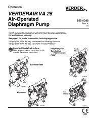
Air-Operated Diaphragm Pumps VERDER VA 15 VERDER VA 15 VERDER VA 20
verderair va 20 - Double Diaphragm Pump
verderair va 20 - Double Diaphragm Pump

Create successful ePaper yourself
Turn your PDF publications into a flip-book with our unique Google optimized e-Paper software.
Service<br />
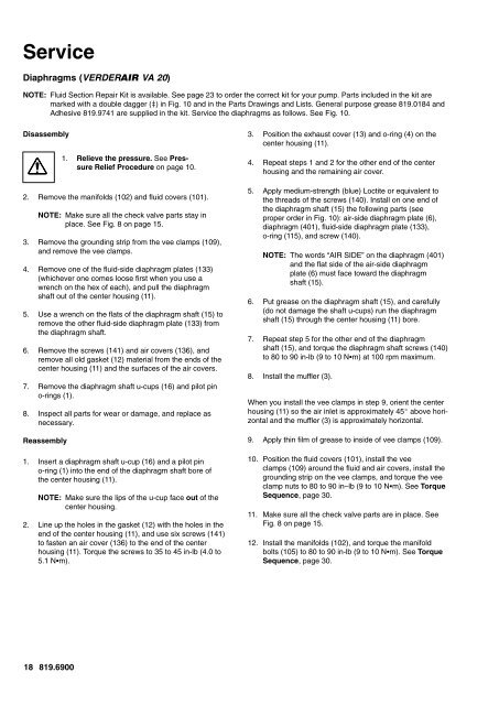
<strong>Diaphragm</strong>s (<strong>VERDER</strong> <strong>VA</strong> <strong>20</strong>)<br />
NOTE: Fluid Section Repair Kit is available. See page 23 to order the correct kit for your pump. Parts included in the kit are<br />
marked with a double dagger () in Fig. 10 and in the Parts Drawings and Lists. General purpose grease 819.0184 and<br />
Adhesive 819.9741 are supplied in the kit. Service the diaphragms as follows. See Fig. 10.<br />
Disassembly<br />
1. Relieve the pressure. See Pressure<br />
Relief Procedure on page 10.<br />
2. Remove the manifolds (102) and fluid covers (101).<br />
NOTE: Make sure all the check valve parts stay in<br />
place. See Fig. 8 on page <strong>15</strong>.<br />
3. Remove the grounding strip from the vee clamps (109),<br />
and remove the vee clamps.<br />
4. Remove one of the fluid-side diaphragm plates (133)<br />
(whichever one comes loose first when you use a<br />
wrench on the hex of each), and pull the diaphragm<br />
shaft out of the center housing (11).<br />
5. Use a wrench on the flats of the diaphragm shaft (<strong>15</strong>) to<br />
remove the other fluid-side diaphragm plate (133) from<br />
the diaphragm shaft.<br />
6. Remove the screws (141) and air covers (136), and<br />
remove all old gasket (12) material from the ends of the<br />
center housing (11) and the surfaces of the air covers.<br />
7. Remove the diaphragm shaft u-cups (16) and pilot pin<br />
o-rings (1).<br />
8. Inspect all parts for wear or damage, and replace as<br />
necessary.<br />
Reassembly<br />
1. Insert a diaphragm shaft u-cup (16) and a pilot pin<br />
o-ring (1) into the end of the diaphragm shaft bore of<br />
the center housing (11).<br />
NOTE: Make sure the lips of the u-cup face out of the<br />
center housing.<br />
2. Line up the holes in the gasket (12) with the holes in the<br />
end of the center housing (11), and use six screws (141)<br />
to fasten an air cover (136) to the end of the center<br />
housing (11). Torque the screws to 35 to 45 in-lb (4.0 to<br />
5.1 Nm).<br />
3. Position the exhaust cover (13) and o-ring (4) on the<br />
center housing (11).<br />
4. Repeat steps 1 and 2 for the other end of the center<br />
housing and the remaining air cover.<br />
5. Apply medium-strength (blue) Loctite or equivalent to<br />
the threads of the screws (140). Install on one end of<br />
the diaphragm shaft (<strong>15</strong>) the following parts (see<br />
proper order in Fig. 10): air-side diaphragm plate (6),<br />
diaphragm (401), fluid-side diaphragm plate (133),<br />
o-ring (1<strong>15</strong>), and screw (140).<br />
NOTE: The words “AIR SIDE” on the diaphragm (401)<br />
and the flat side of the air-side diaphragm<br />
plate (6) must face toward the diaphragm<br />
shaft (<strong>15</strong>).<br />
6. Put grease on the diaphragm shaft (<strong>15</strong>), and carefully<br />
(do not damage the shaft u-cups) run the diaphragm<br />
shaft (<strong>15</strong>) through the center housing (11) bore.<br />
7. Repeat step 5 for the other end of the diaphragm<br />
shaft (<strong>15</strong>), and torque the diaphragm shaft screws (140)<br />
to 80 to 90 in-lb (9 to 10 Nm) at 100 rpm maximum.<br />
8. Install the muffler (3).<br />
When you install the vee clamps in step 9, orient the center<br />
housing (11) so the air inlet is approximately 45 above horizontal<br />
and the muffler (3) is approximately horizontal.<br />
9. Apply thin film of grease to inside of vee clamps (109).<br />
10. Position the fluid covers (101), install the vee<br />
clamps (109) around the fluid and air covers, install the<br />
grounding strip on the vee clamps, and torque the vee<br />
clamp nuts to 80 to 90 in–lb (9 to 10 Nm). See Torque<br />
Sequence, page 30.<br />
11. Make sure all the check valve parts are in place. See<br />
Fig. 8 on page <strong>15</strong>.<br />
12. Install the manifolds (102), and torque the manifold<br />
bolts (105) to 80 to 90 in-lb (9 to 10 Nm). See Torque<br />
Sequence, page 30.<br />
18 819.6900