Air-Operated Diaphragm Pumps VERDER VA 15 VERDER VA 15 VERDER VA 20
verderair va 20 - Double Diaphragm Pump
verderair va 20 - Double Diaphragm Pump

You also want an ePaper? Increase the reach of your titles
YUMPU automatically turns print PDFs into web optimized ePapers that Google loves.
Service<br />
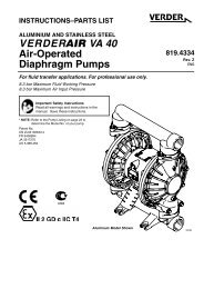
<strong>Air</strong> Valve (<strong>VERDER</strong> <strong>VA</strong> <strong>15</strong> and <strong>VERDER</strong> <strong>VA</strong> <strong>20</strong> <strong>Pumps</strong>)<br />
NOTE: <strong>Air</strong> Valve Repair Kit 819.9740 is available. Parts included in the kit are marked with a dagger () in Fig. 6 and in the Parts<br />
Drawings and Lists. A tube of general purpose grease 819.0184 is supplied in the kit. Service the air valve as follows.<br />
See Fig. 6.<br />
1. Relieve the pressure. See Pressure<br />
Relief Procedure on page 10.<br />
2. Remove the cover (10) and the o-ring (4).<br />
3. Remove the carriage plungers (7), carriages (8),<br />
carriage pins (9), and valve plate (14) from the center<br />
housing (11).<br />
4. Clean all the parts, and inspect them for wear or<br />
damage.<br />
NOTE: If you are installing the new <strong>Air</strong> Valve Repair<br />
Kit 819.9740, use all the parts in the kit.<br />
5. Grease the lapped surface of the valve plate (14), and<br />
install the valve plate with the lapped surface facing up.<br />
6. Grease the bores of the center housing (11), install the<br />
u-cup packings (2) on the carriage plungers (7), and<br />
slide the carriage plungers into the carriage plunger<br />
bores. See the following important installation notes:<br />
NOTES:<br />
<br />
<br />
When you install each u-cup packing (2) on each carriage<br />
plunger (7), make sure the lips of the u-cup packing face<br />
toward the clip end (the smaller end) of the carriage<br />
plunger.<br />
When you slide the carriage plungers (7) into the bores,<br />
slide them in with the clip ends (the smaller ends) facing<br />
toward the center of the center housing (11).<br />
7. Grease the carriage pins (9), and slide the carriage pins<br />
into the carriage pin bores.<br />
8. Install the carriages (8). Make sure the carriages engage<br />
the clip ends of the carriage plungers (7) and carriage<br />
pins (9).<br />
9. Grease the o-ring (4), and seat it in the groove around<br />
the cover opening of the center housing (11).<br />
10. Screw cover (10) into center housing, and torque cover<br />
from 80 to 100 in–lb (9.0 to 13.6 Nm).<br />
NOTE: Center housing (11) is shown separated from the<br />
air covers, but it is not necessary to remove the air<br />
covers for this service. Leave the center housing<br />
and air covers assembled for this service.<br />
5<br />
4<br />
2<br />
4 6<br />
8<br />
7<br />
5<br />
4<br />
4 6<br />
2<br />
7<br />
3<br />
14<br />
1<br />
10<br />
Included in <strong>Air</strong> Valve Repair Kit 819.9740.<br />
4 2<br />
1<br />
2<br />
3<br />
4<br />
Torque to 80 to 100 in-lb (9.0 to 13.6 Nm).<br />
Apply grease.<br />
Apply grease to lapped face.<br />
Apply grease to bores of center housing (11) before installing.<br />
11<br />
5<br />
6<br />
Fig. 6<br />
Seal lips face clip end (the smaller end) of carriage plunger (7).<br />
Install with the clip ends (the smaller ends) facing toward center of<br />
center housing (11).<br />
9<br />
2<br />
8<br />
9<br />
2<br />
9069A<br />
819.6900 13