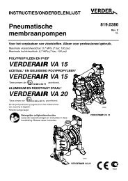
Air-Operated Diaphragm Pumps VERDER VA 15 VERDER VA 15 VERDER VA 20
verderair va 20 - Double Diaphragm Pump
verderair va 20 - Double Diaphragm Pump

You also want an ePaper? Increase the reach of your titles
YUMPU automatically turns print PDFs into web optimized ePapers that Google loves.
Installation<br />
<strong>Air</strong> Line<br />
Warning<br />
A bleed-type master air valve (B) is required in your system<br />
to relieve air trapped between this valve and the pump.<br />
See Fig. 2. Trapped air can cause the pump to cycle unexpectedly,<br />
which could result in serious injury, including<br />
splashing in the eyes or on the skin, injury from moving<br />
parts, or contamination from hazardous fluids.<br />
Caution<br />
The pump exhaust air may contain contaminants. Ventilate<br />
to a remote area if the contaminants could affect your fluid<br />
supply. Read <strong>Air</strong> Exhaust Ventilation on page 6.<br />
1. Install the air line accessories as shown in Fig. 2. Mount<br />
these accessories on the wall or on a bracket. Be sure<br />
the air line supplying the accessories is electrically conductive.<br />
a. The fluid pressure can be controlled in either of two<br />
ways. To control it on the air side, install an air regulator<br />
(G). To control it on the fluid side, install a fluid<br />
regulator (J) near the pump fluid outlet (see Fig. 2).<br />
b. Locate one bleed-type master air valve (B) close<br />
to the pump and use it to relieve trapped air. Read<br />
the Warning above. Locate the other master air<br />
valve (E) upstream from all air line accessories and<br />
use it to isolate them during cleaning and repair.<br />
c. The air line filter (F) removes harmful dirt and<br />
moisture from the compressed air supply.<br />
2. Install an electrically conductive, flexible air hose (C)<br />
between the accessories and the 1/4 npt(f) pump air<br />
inlet. Use a minimum 1/4 in. ID air hose. Screw an air<br />
line quick disconnect coupler (D) onto the end of the air<br />
hose (C), and screw the mating fitting into the pump air<br />
inlet snugly. Do not connect the coupler (D) to the fitting<br />
yet.<br />
Installation of Remote Pilot <strong>Air</strong>lines<br />
1. Connect the air line to the pump as noted above.<br />
2. Connect 1/4 OD tubing to the push type connectors (16)<br />
on the underside of the pump.<br />
NOTE: By replacing the push type connectors, other sizes<br />
or types of fittings may be used. The new fittings will<br />
require 1/8 in. npt threads.<br />
3. Connect the other end of the tubes to the external air<br />
signal, such as <strong>VERDER</strong>’s Cycleflo (PN 819.9742) or<br />
Cycleflo II (819.9743) controllers.<br />
NOTE: The air pressure at the connectors must be at least<br />
30% of the air pressure to the air motor for the pump<br />
to operate.<br />
Fluid Suction Line<br />
If using a conductive (acetal or polypropylene) pump, use<br />
conductive hoses. If using a non-conductive pump,<br />
ground the fluid system. Read Grounding on page 8.<br />
The fluid inlet port is 1/2 in. or 3/4 in..<br />
<br />
At inlet fluid pressures greater than <strong>15</strong> psi; 0.1 MPa<br />
(1 bar), diaphragm life will be shortened.<br />
Fluid Outlet Line<br />
Warning<br />
A fluid drain valve (H) is required in your system to relieve<br />
pressure in the hose if it is plugged. See Fig. 2. The drain<br />
valve reduces the risk of serious injury, including splashing<br />
in the eyes or on the skin, or contamination from hazardous<br />
fluids when relieving pressure. Install the valve close to<br />
the pump fluid outlet.<br />
1. Use electrically conductive fluid hoses (K). The pump<br />
fluid outlet is 1/2 in. or 3/4 in. Screw the fluid fitting into<br />
the pump outlet snugly. Do not over–tighten.<br />
2. Install a fluid regulator (J) at the pump fluid outlet to control<br />
fluid pressure, if desired (see Fig. 2). See <strong>Air</strong> Line,<br />
step 1a., for another method of controlling pressure.<br />
3. Install a fluid drain valve (H) near the fluid outlet. Read<br />
the warning above.<br />
819.6900 5